1
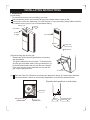
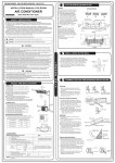
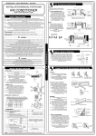
1. Wire connecting
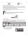
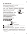
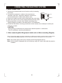
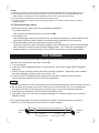
1. Remove the right-side front panel from the unit .
2. Connect the connective cables to the terminals as
identified with their respective matched numbers on
the terminal block of indoor and outdoor units.
3. Secure the cable onto the control board with the cord clamp.
4. Reinstall the right-side front panel to its original position after
finishing the wire connection.
5. Wiring connection must be done strictly according to the
Wiring Diagram located on the side panel of air conditioner .
6. Follow the instructions of wiring connection in this manual, never
attempt to modify the wiring by yourself.
Connective Cable
Connective Pipe
Right-side
front panel
Model B
CAUTION
Wrong wiring connections may cause some electrical parts to malfunction. The air conditioner must
be grounded well.
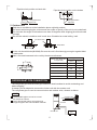
Connect the cable between the outdoor unit
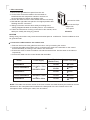
1. Remove the front air-inlet grille from the indoor unit by loosening the screws.
2. Connect the cable to the indoor unit by connecting the wires to the terminals on the control
board individually according to the outdoor unit connection.
3. Ensure the colour of wires of outdoor unit and the terminal Nos. Are the same to the indoor,s
respectively.
4. Secure the cable onto the control board with the holder.
Model
Input Rated Amp
(Switch/Fuse)
Power supply
<30000Btu/h
30000~48000Btu/h
220-240V~ 50Hz
or
208-230V~60Hz
>48000Btu/h
30000~48000Btu/h
>48000Btu/h
380-420V~ 50Hz
or
380-420V~60Hz
Power Cord Size
32/25A
2.5mm2
63/50A
4mm2
63/50A
6mm2
16/16A
1.5mm
32/25A
2.5mm
2
2
NOTE: The cable size and the current of the fuse or switch are determined by the maximum current
indicated on the nameplate which located on the side panel of the unit. Please refer to the
nameplate before selecting the cable, fuse and switch.
11