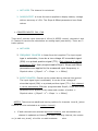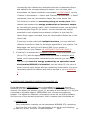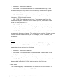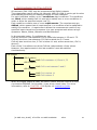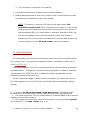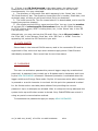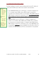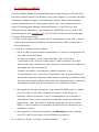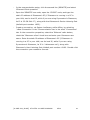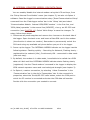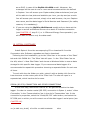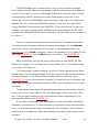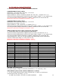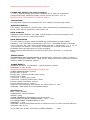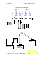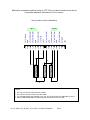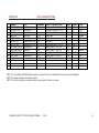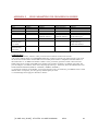
1
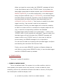
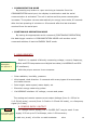
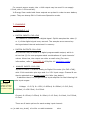
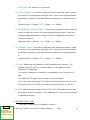
STYLITIS-10 USER’S MANUAL 0508 Copyright 2006-2014, SYMMETRON Electronic Applications. Eighth edition in English. May 2014. No part of this publication may be reproduced, stored in retrieval system, or transmitted, in any form by any means, without the prior written permission of Symmetron Company. Information furnished by Symmetron is believed to be accurate and reliable; however, no responsibility is assumed for its use. No license is granted by implication or otherwise. Symmetronis a registered trademark and Stylitisis a trademark of the Symmetron Company. All other trademarks belong to their respective owners. THE WARRANTY DOES NOT EXTEND TO AND SHALL NOT APPLY TO: 1. Products, which have been repaired or altered by other than Symmetron's personnel, unless Buyer has properly altered or repaired the products in accordance with procedures previously approved in writing by Symmetron. 2. Products, which have been subject to misuse, neglect, accident, improper installation, or direct lightning strikes. THE WARRANTY AND REMEDIES SET FORTH ABOVE ARE IN LIEU OF ALL OTHER WARRANTIES EXPRESSED OR IMPLIED, ORAL OR WRITTEN, EITHER IN FACT OR BY OPERATION OF LAW. THE SYMMETRON COMPANY SHALL HAVE NO LIABILITY FOR INCIDENTAL OR CONSEQUENTIAL DAMAGES OF ANY KIND ARISING OUT OF THE SALE, INSTALLATION, OR USE OF ITS PRODUCTS. RETURN FROM OUTSIDE GREECE: Contact Symmetron for authorization and shipping instructions. SYMMETRON ELECTRONIC APPLICATIONS TEL: (+30)-210-603-4002 FAX: (+30)-210-603-4003 e-mail: [email protected] Internet: http://www.symmetron.gr/ Made in Greece. 2 [S-UME-S10_B-005] STYLITIS-10 USER’S MANUAL 0514 CONVENTIONS USED IN THIS MANUAL Symbol Meaning To avoid injury of personnel and/or damage to the instrument, the operator must refer to the user’s manual. CAUTION Calls attention to a procedure or condition which, if not correctly performed could result in damage to the instrument. N. Hadzidakis – T. Katsabakou Co. 1, Antikythiron Street 15344 Gerakas, Greece MANUFACTURERS DECLARATION OF CONFORMITY We, the undersigned, hereby declare that the equipment specified conforms to the below Directives and Standards. Standards to which Conformity is Declared EMC Emmisions: ΕΝ55022, EN61000-4-3 EMC Immunity: EN61000-4-2, EN61000-4-4, EN61000-4-5, EN61000-4-6 Safety: EN61010-1 Description of Equipment: Data recording and logging instruments. Model Stylitis-10 Batch of product covered Serial numbers: 037Α0146 to 037Α0241, 041A0242 to 041A0xxx Date and Place Gerakas, Greece, 28th May 2014 Authorized signatory on behalf of the manufacturer Nick Hadzidakis Theoni Katsabakou Title: Owners and Directors, Symmetron N. Hadjidakis-T. Katsabakou Co. [S-UME-S10_B-005] STYLITIS-10 USER’S MANUAL 0514 3 CONTENTS 1. INTRODUCTION ............................................................................. 6 2. OPERATION AND SAFETY ......................................................... 10 3. USER INTERFACE AND OPERATIONS REVIEW....................... 11 4. POWER SUPPLY.......................................................................... 14 5. MEASUREMENTS ........................................................................ 15 6. SENSOR SUPPLY OUTPUT ........................................................ 15 7. CHANNELS................................................................................... 16 8. PROGRAMMABLE DIGITAL OUTPUTS ...................................... 21 9. DATA PROCESSING AND STORAGE ........................................ 22 10. DATA RECORDING .................................................................... 22 11. DATA RETRIEVAL ..................................................................... 23 12. DATA SAFETY ........................................................................... 24 13. PASSWORD ............................................................................... 24 14. COMMUNICATION SERIAL PORTS .......................................... 25 15. INTERNAL ETHERNET .............................................................. 26 16. INTERNAL GSM/GPRS MODEM: GSM DATA CALLS ............. 28 17. INTERNAL GSM/GPRS MODEM: GPRS CONNECTIONS ........ 29 18. MESSAGES (SMS AND EMAIL) ................................................ 32 19. OPTON 4 SOFTWARE ............................................................... 34 20. GPS MODULE ............................................................................ 36 4 [S-UME-S10_B-005] STYLITIS-10 USER’S MANUAL 0514 21. TECHNICAL CHARACTERISTICS ............................................. 37 APPENDIX A CONNECTION EXAMPLES ................................. 39 APPENDIX B DATA LOGGER SETTINGS ................................ 41 APPENDIX C CALCULATION OF WIND TURBINE ENERGY PRODUCTION FROM WIND SPEED ............................................... 42 APPENDIX D COMMANDS ................................ 43 APPENDIX E GPRS PARAMETERS FOR PROVIDERS IN GREECE 47 [S-UME-S10_B-005] STYLITIS-10 USER’S MANUAL 0514 5 1. INTRODUCTION The model Stylitis-10 data logger is a versatile, low cost and user friendly device for technical measurements, control and data storage. It provides: A local user interface with 2 line - LCD display and 4 keybuttons. Standard connection for most widely used transducers, like thermometers, anemometers, wind direction vanes, pyranometers, switches, etc. User selectable time interval for average calculations. Internal flash memory 4 Mbyte for data storage Digital outputs that may be programmed to switch ON or OFF external relays, LEDs, etc. The outputs may be set to respond to combinations of input channels’ values. Programming, control and data downloading through RS232, modem, internal or external GSM/GPRS modem, Ethernet. Sampling and storage continues unaffected while communicating with the user. WORKING WITH STYLITIS Stylitis family data loggers operate in different ways according to your application. (see fig.2): 1. As an autonomous unit with off-line data downloading. The data logger samples the input signals and keeps the average values for each interval in the internal 2MB flash memory. The stored files are downloadable via the serial port. The connection between data logger and the PC may be via a direct link, via a modem (PSTN or GSM) or via the Ethernet network (LAN). The unit accepts an optional internal GSM modem or Ethernet server (in this case the ‘COMMUNICATION’ 6 [S-UME-S10_B-005] STYLITIS-10 USER’S MANUAL 0514 serial port is disabled). The PC must be equipped with an RS232 COM port, a modem or a network card respectively. The data logger is accompanied by Opton, the software required for programming, inspecting, data downloading, and decompression. Data files are arranged in ASCII text files. 2. Real Time Measurements. On line data reading with appropriate user software, for storing and manipulation in a PC. The connection between data logger and the PC is as described above. This manual includes detailed operation description. Technical support is available by phone: +30- 210-6034002, or email: [email protected] and at: www.symmetron.gr [S-UME-S10_B-005] STYLITIS-10 USER’S MANUAL 0514 7 Fig 1: General Diagram LC Display Li Bat Real Time Clock RS232 ADC Internal Supplies Int. Bat. Counter Circuit CPU Keyboard REG 1 counter input: CH1 or digital output +2.5V Reference Input / Output Protection Flash memory 4 MB 1 channel (ch8) configurable as: counter input (only TTL level), voltage or current input, digital input or digital output 1 precision +2.5V output 1 precision 0.5mA output 6~15VDC Ext. Bat. 8 6 channels (ch2~7) configurable as: voltage or current inputs, digital inputs or digital outputs STYLITIS-10 USER’S MANUAL Fig. Stylitis-10 PC 2: Operation Sensor 1 Use wire (up to 15 m) for setup and data downloading. RS-232 port Sensor 2 RS-232 Port Internal flash Memory Use a modem for setup and data downloading. Sensor n Wired modem Wireless (GSM) modem Base station M odeSE TUP m Use local network for setup and data downloading. Network card 10BaseT Serial server [S-UME-S10_B-005] STYLITIS-10 USER’S MANUAL 0514 9 2. OPERATION AND SAFETY EXTERNAL DESCRIPTION. Front View 2 line-LCD-display CAUTION Do not: - destroy - overheat - short-circuit - charge dry cells. If the instrument will not be used for a long time, remove the dry cells. Keyboard Input/Output connectors RS232 port, D9Μ to be connected with modem or PC RS232 port, peripheral for general input/output use. Back panel: 1 battery case PP3 (9V). Use of alkaline batteries is advised. FUSE REPLACEMENT. CAUTION The fuse used must of the specified raAcq On/Off The instrument uses a 1 A power supply fuse, which must be replaced if blown (supply voltage out of limits). It can be found on the printed circuit board, after removing the 4 screws that hold the back panel in place. Make sure you have removed the external supply and cells before attempting the replacement. shortcircuit the fuse holder. 10 [S-UME-S10_B-005] STYLITIS-10 USER’S MANUAL 0514 3. USER INTERFACE AND OPERATIONS REVIEW The display and keyboard may be used to: To see the current status and time. To check the battery. To check the amount of free memory. To check the current input data values. To check the modem signal. To check the input setup. To start or stop data storing (ACQuisition OFF/ON). To activate or deactivate the internal server (internal GSM/GRPS modem or internal Ethernet module, if there are any) To type the service code, to deactivate outputs and alarms for the data logger’s service. [S-UME-S10_B-005] STYLITIS-10 USER’S MANUAL 0514 11 MENU STRUCTURE NOTES: 1. The parameter setting is done through serial port and is permitted only if ACQUISITION is OFF. 2. From local interface only system inspection is possible and the change of ACQUISITION status (ON/OFF). 3. Channel types are explained in the table in next page. KEYS MENU Go to next menu SELECT Accept change and go to next menu > Go to next sub-menu ^ Change setting 12 [S-UME-S10_B-005] STYLITIS-10 USER’S MANUAL 0514 Channel type C Channel Input signal Operation 1 SIN C 1,8 TTL E 1 SIN E 1,8 TTL A 2,3,4,5,6,7,8 VOLTAGE A 2,3,4,5,6,7,8 CURRENT V 5,6,7 T 2,3,4,5,6,7,8 I 2,3,4,5,6,7,8 O 1,2,3,4,5,6,7,8 DIGITAL BUS 10~19 (connected to PERIPHERAL port) Measures the number of sinusoidal periods per second and applies the formula: [Slope2 * x2 + Slope * x + Offset]. Stores the average for each interval. Measures the number of TTL pulses per second and applies the formula: [Slope2 * x2 + Slope * x + Offset]. Stores the average for each interval. Measures and stores the number of sinusoidal periods inside interval and applies the formula: [Slope2 * x2 + Slope * x + Offset] (Event counting) Measures and stores the number of TTL pulses inside interval and applies the formula: [Slope2 * x2 + Slope * x + Offset] (Event counting) Measures analog voltage per second. Applies the formula: [Slope2 * x2 + Slope * x + Offset]. Stores the average for each interval. Measures analog current per second. Applies the formula: [Slope2 * x2 + Slope * x + Offset]. Stores the average for each interval. Measures wind direction (vane). Measures the ratio: (Input voltage)/(Pulsed Out Voltage) per second, adds offset and converts to degrees. Calculates and stores vector direction average for each interval. Temperature sensor PT100 or PT1000. Measures analog voltage per second and applies conversion formula for PT100 or PT1000. Stores averages for each interval. Measures the digital input state (TTL 0/1) every second. Stores sum of input states for each interval. Digital output (open-drain) according to user defined conditions. If the data logger’s PERIPHERAL port is upgraded for digital bus sensors, MODBUS RTU (RS-485) or SDI-12, register values are measured once every interval. SERVICE CODE While in the first menu (‘STATUS’), press ‘^’. In the LCD screen, the ‘SERVICE PASSWORD?’ message will appear. This password consists of 6 digits, between 1 and 4. To type it, use the data logger’s buttons, with the following correspondence: press ‘MENU’ for 1, ‘SELECT’ for 2, ‘>’ for 3 and ‘^’ for 4. [S-UME-S10_B-005] STYLITIS-10 USER’S MANUAL 0514 13 When you type the correct code, the ‘SERVICE’ message will blink in the right bottom part of the ‘STATUS’ menu. In this state, the data logger deactivates its digital outputs (see 8.PROGRAMMABLE DIGITAL OUTPUTS), if you have selected any in the data logger’s setup via Opton software (see 19. SOFTWARE), via the Read Setup and Write Setup commands. Therefore, since the digital outputs are deactivated, the Alarm SMSs are also deactivated (see 18. MESSAGES (SMS and EMAIL)). This function is useful for the data logger’s service, if eg a sensor needs to be temporarily disconnected. This way, the data logger will not be busy sending an SMS or an alarm which is connected to a digital output will not ring, in case the corresponding conditions are satisfied. The data logger exits this state if you press again ‘^’ while in the ‘STATUS’ menu. It will request the code again. Type any code, and the data logger will exit this state (the ‘SERVICE’ message will cease to blink in the ‘STATUS’ menu). In this case (to exit the service state), the ERROR message is of no importance. You can set this code by connecting with the data logger via Opton and selecting the command ‘Set Service Code’. Finally, you can enter SERVICE remotely via Opton software as well (but you cannot enter SERVICE mode), in case the data logger was left in SERVICE mode by mistake. 4. POWER SUPPLY There are 3 modes of operation: ENERGY SAVING MODE This is the default mode. The system is in an idle condition, which is interrupted by the system clock every second, in order to take the input sampling, perform any calculation and store the data in memory. During this low consumption mode the display is off. 14 [S-UME-S10_B-005] STYLITIS-10 USER’S MANUAL 0514 COMMUNICATION MODE By pressing any button or upon receiving a character from the COMMUNICATION serial port, the display is switched on and the serial communication is activated. The unit is active and the power consumption increases. The system returns automatically to energy save mode, 60 seconds after the last pressing of a button or 60 seconds after the last character received from the serial port. CONTINUOUS OPERATION MODE By issuing the appropriate serial command (CONTINUOUS OPERATION) the data logger remains in COMMUNICATION MODE until another serial command switches it back to ENERGY SAVE mode. 5. MEASUREMENTS Stylitis-10 is capable of directly measuring voltage, current, frequency, Connection Examples: pulses and RTD temperature and digital bus data (via MODBUS and SDI- See Appendix A. 12 interfaces). With the proper sensors it can measure: Solar radiation, humidity, pressure. Wind speed, wind direction. It connects with many types of anemometers and vane sensors. Rain height, water speed, water depth, etc Electrical energy measuring pulses Via MODBUS interface: AC voltage, current and power The analog and counter sensors must output Voltage (from 0~125mV to 0~2.5V full-scale), current (from 0~5mA to 0~50mA full-scale), or a frequency signal (0~5 kHz). 6. SENSOR SUPPLY OUTPUT CAUTION Do not apply Voltage to device’s output. For voltage sensor supply, the + PULSED OUT may be used. It can supply 2.5V at up to 25 milliamps, with 0.2% accuracy. [S-UME-S10_B-005] STYLITIS-10 USER’S MANUAL 0514 15 For current sensor supply, the + AUX output may be used. It can supply 0.5mA, with 0.3% accuracy. In Energy Save mode both these outputs are pulsed in order to save battery power. They are always ON in Continuous Operation mode. 7. CHANNELS A. CHANNELS 1~9 DIGITAL INPUTS: CH2~CH8 The channel is connected to a digital signal. Stylitis samples the value (0 or 1) of the digital signal every second. The samples are summed up during selected interval and stored in memory. DIGITAL OUTPUTS: CH1~CH8 Any channel may be used as a digital programmable output, which is driven low (0) for user-programmable combinations of input channels’ values. When low, the output can drive a small relay (For more information, refer to CHAPTER 19 of Stylitis-10 installation guide.) ANALOG INPUTS: CH2~CH8 Stylitis-10 has a 7-channel Analog to Digital Converter (for CH2~CH8), with 13 bit-resolution plus sign and 0~+2.5V input range. Channel 8 can also be selected as a counter input of 16 bits (see below). In addition there is a programmable input amplifier for the following full scale input ranges: CAUTION Do not apply Voltage exceeding the limit of (20V to system’s Inputs Voltage: 0~2.5V, 0~1.25V, 0~625mV, 0~500mV, 0~312,5mV, 0~250mV, 0~156.25mV, 0~125mV. Current: 0~50mA, 0~25mA, 0~20mA, 0~12.5mA, 0~10mA, 0~6.25mA, 0~5mA. There are 6 basic options for each analog input channel: 16 [S-UME-S10_B-005] STYLITIS-10 USER’S MANUAL 0514 1. NOT USED. The channel is not stored. 2. VOLTAGE INPUT. A formula is applied to the measured value in order to convert it to appropriate physical units. Three user-programmable parameters, Slope2, Slope and Offset are applied to measured value x: Physical value = [Slope2 * x2 + Slope * x + Offset]. 3. DIFFERENTIAL VOLTAGE INPUT. A formula is applied to the measured value in order to convert it to appropriate physical units. Three userprogrammable parameters, Slope2, Slope and Offset are applied to measured value x: Physical value = [Slope2 * x2 + Slope * x + Offset]. 4. CURRENT INPUT. A formula is applied to the measured value in order to convert it to appropriate physical units. Three user-programmable parameters, Slope2, Slope and Offset are applied to measured value x: Physical value = [Slope2 * x2 + Slope * x + Offset]. 5. VANE. Measures wind direction from potentiometric sensors. The Voltage input 0V~2.5V is transformed to 0~360 degrees, with resolution 2.8 degrees. The vector averaging is needed for continuation from 360 deg. to 0 deg. The offset (0~359 deg.) from north is user selectable. E.g. if the vane alignment is 30 East the offset must be set 30, if the vane alignment is 30 West the offset must be set 330 (=360-30). 6. RTD. Measures temperature with PT100 or PT1000 type sensors and an external precision resistor. (see Appendix Α). A conversion formula is applied internally. BATTERY INPUT: CH9 There are 2 options for the Battery channel: CAUTION Do not apply Voltage exceeding the limit of (20V to system’s Inputs [S-UME-S10_B-005] STYLITIS-10 USER’S MANUAL 0514 17 1. NOT USED. The channel is not stored. 2. SLOPE/OFFSET. A linear formula is applied to display battery voltage with an accuracy of 5%. The Slope & Offset parameters have fixed values. COUNTER INPUTS: CH1, CH8 There are 2 counter input channels of 16-bit (0-65535 counts), channels 1 and 8. Channel 8 can also be selected as an analog input (see above). There are 3 basic options: 1. NOT USED. 2. FREQUENCY COUNTER. A linear formula is applied. The input signal type is selectable; it can be a low voltage AC sinusoidal signal (SIN) or a pulsed positive signal (ΤΤL). Only channel 1 can be selected as SIN. User programmable Slope2, Slope and Offset parameters are applied to the measured input frequency x: Physical value = [Slope2 * x2 + Slope * x + Offset]. 3. EVENT COUNTER. Counts-up the pulses during interval time period. The input signal type is selectable; it can be a low voltage AC sinusoidal signal (SIN) or a pulsed positive signal (ΤΤL). Only channel 1 can be selected as SIN.User programmable Slope2, Slope and Offset parameters are applied to the measured number of pulses x: Physical value = [Slope2 * x2 + Slope * x + Offset]. NOTES: There are two additional storing options for channels 1 and 8, (when channel 8 is also selected as a counter channel). 1. If both channels are selected as event counters, one accumulator per channel is updated as following: At each recording interval, the events 18 [S-UME-S10_B-005] STYLITIS-10 USER’S MANUAL 0514 recorded by each channel are multiplied with the corresponding Slope and added to the corresponding accumulator. You can reset each accumulator via Opton 4 software (see chapter 19.SOFTWARE), via the ‘Channel 1 Accumulator -> Reset’ and ‘Channel 8 Accumulator -> Reset’ commands, from the ‘Accumulator Status’ bar in the ‘Home’ tab. This function is useful for measuring energy at a solar plant. Each channel can measure the energy produced at an inverter’s output, by connecting an energy meter, which measures events, and by typing the appropriate Slope for the sensor. You can see the total energy produced in each channel’s accumulator via Opton 4, with the Get values from Logger command, from the ‘Accumulator Status’ bar in the ‘Home’ tab. If you have a solar plant with multiple inverters, you may use both channels to perform a test for the proper operation of your system. The data logger can send you a PV alarm SMS if your system is malfunctioning. (see Chapter 18. MESSAGES (SMS AND EMAIL)). 2. If channel 1 is selected as a Frequency counter of the appropriate type (Sin or TTL) with the appropriate Slope and Offset to measure wind speed, via an anemometer connected to the channel, you can view in real-time the electrical energy produced by an equivalent small wind turbine BEFORE it is installed, such as Viking 25, the rotor of which is at the same height with the measuring anemometer. For more information about this feature and how to activate it, go to APPENDIX C. B. DIGITAL BUS CHANNELS (MODBUS RTU and SDI-12) If the data logger’s PERIPHERAL port is upgraded for digital bus sensors, MODBUS RTU (RS-485) or SDI-12, register values are measured once every interval. The digital bus sensors (up to 10, as many as the channels 10~19) are connected to the data logger’s PERIPHERAL port, via the accompanying adaptor. The digital bus channels’ perameters can be set via Opton software, like the ones of the remaining channels. Such a channel can be selected as: MODBUS RTU Only consecutive channels can be selected as MODBUS RTU, beginning from the first one (ch10). The parameters to be set are the following: [S-UME-S10_B-005] STYLITIS-10 USER’S MANUAL 0514 19 - ADDRESS. The sensor’s address. - REGISTER. The register values to be measured. According to the measurement, this may be the first of the many consecutive register values which will be measured in the same channel. - REG. FORMAT. The register values’ format, eg 16-bit unsigned integers or 32-bit signed integers. - REG. TYPE. The register values’ type. They can be read from the sensor as they are, or with a certain scale, eg FIX1, if the value read must be multiplied with 0.1. - REG. ORDER. The order of the bytes and words with which the values read appear. Besides the classic order Big Endian (high byte first, high word first), all combinations are available. - VALUES. The number of the consecutive register values which will be measured in the same channel. This option has a meaning if these values concern similar measurements (eg if 3 voltages, of the 3 phases, are measured). SDI-12 Only consecutive channels can be selected as SDI-12, beginning from the first one after the MODBUS RTU channels (if any are selected). The parameters to be set are the following: - ADDRESS. The sensor’s address. - REGISTER. The register value to be measured (the available values are 0~9). A value usually consists of many measurements, even different ones (eg wind speed and direction). - VALUES. The number of measurements of a register value which will be recorded in Stylitis-10’s file, beginning from the first one. NOT USED The remaining (last) channels, after the MODBUS RTU and the SDI-12 ones, that are not used, remain NOT USED. 20 [S-UME-S10_B-005] STYLITIS-10 USER’S MANUAL 0514 8. PROGRAMMABLE DIGITAL OUTPUTS All channels (CH1-CH8) may be programmed as digital outputs. The output state can be either set manually HIGH or LOW or set to get its value automatically according to measured values of input channels: For each individual output, up to 5 conditions may be defined. The conditions are ORed, which means that it is enough to satisfy one or more conditions in order to drive the specified output Low (0). Each condition contains one or more requirements. The requirements are ANDed, which means that all requirements in a condition must be satisfied to satisfy this condition. A requirement utilizes the measurement result of any specified input channel and compares it to user-programmed values using 4 operators: Above, Below, Between and Not Between. In the example below, 3 conditions are set: Ch8 will be driven low whenever Ch5’s value falls between 1.25 and 1.75. Ch8 will be driven low whenever Ch2 falls outside the 3~5 zone. Ch8 will also be driven low, if Ch1 is below 11 and, at the same time, Ch6 is above 2. Each of the 3 conditions can drive Ch8 low independently of the others. However, the requirements in the last condition must be satisfied simultaneously. Ch8 Output OR Condition AND Ch5 is between 1,25 and 1,75 OR Condition AND Ch2 is not between 3 and 5 OR Condition AND Ch1 is below 11 AND Ch6 is above 2 When the digital output is LOW, the switch closes and the channel is shortcircuited to GROUND. In this state, it can drive a small relay. For more information, refer to CHAPTER 19 of Stylitis-10 installation guide. [S-UME-S10_B-005] STYLITIS-10 USER’S MANUAL 0514 21 9. DATA PROCESSING AND STORAGE The statistical interval is user selectable from 1 second to 60 minutes. Inputs are measured per second and their values are placed in temporary storage. Math processing is selectable: Average values only or Average, Minimum and Maximum values. At the end of the time interval, the values are calculated and stored simultaneously in the internal 4MB FLASH Memory and in the removable 2GB SD Flash card (if one has been inserted). NOTE: For Stylitis-10 F/W versions 3.40 or newer, the internal Flash memory is cyclic, ie instead of getting full, it continues recording from the beginning, overwriting older files. All files are be stored in the SD card. For security reasons, stored files have a time mark, which appears in every record and corresponds to the end of statistical interval time. Stored data is organized in files, which are kept even without supply power. For enhanced data safety each individual record is marked with its own time stamp. 10. DATA RECORDING During recording Upon selection of acquisition ON the following happen: (acquisition on): no change of parameters is permitted. 1. A new file is opened in the SD Flash (if one has been inserted) and the internal Flash memory. 2. Recording starts according to user set parameters. Upon selection of acquisition OFF the following happen: Only when acquisition is off 1. Recording stops. parameter 2. The file is closed in both memories. change is permitted. When downloading the current file during recording: 1. The file closes in both memories. 2. The download starts. 22 [S-UME-S10_B-005] STYLITIS-10 USER’S MANUAL 0514 3. The recording is continued in a new file. File downloading does not disturb the recording process Default data download is from file currently open. Previous files can also be retrieved, as explained in the next chapter. NOTE: To remove or insert an SD card to the data logger, the acquisition must be OFF! If it is ON when you insert it, it will not be recognized and no data will be recorded in the card. If you remove it with acquisition ON (or in case power is lost with acquisition ON), the file will not appear in the card's file directory (see next chapter), therefore you will not be able to download it from the data logger, but only to retrieve it via an SD card reader (see next chapter). 11. DATA RETRIEVAL File downloading and memory erasure are done via serial commands (direct link, modem, etc.), using the accompanying Opton 4 software in the host PC (See CHAPTER 19). Files downloaded to a PC are compressed to save memory space and speed up data transfer. The data are retrieved using the Opton 4 software. Data are decompressed to ASCII text files, suitable for further manipulation using available programs like Excel, etc. Via the ‘Download logger memory data’ from Opton 4’s ‘Home’ tab or from the ‘Data logger’ bar of the ‘Files’ tab, the following file downloading options appear: A. If there is no SD card inserted in the data logger, the data you will download are recorded in the internal Flash memory. You may download: 1. The most recent file. The file closes before it is downloaded, and a new file begins (see previous chapter). 2. One single previous file or more previous files. You can type the number of a single file or a range of files (e.g. 1-4) [S-UME-S10_B-005] STYLITIS-10 USER’S MANUAL 0514 23 B. If there is an SD Card inserted in the data logger, the data you will download are recorded in the internal Flash memory and in the SD card simultaneously. You may download: 1. The directory of the card's files which appears in the 'Home' tab, in the 'SD Card directory' bar. The directory shows each file's number, Start date, size and start page, so that you will know which file(s) to download. 2. The most recent file. The file closes before it is downloaded, and a new file begins(see previous chapter). 3. One single previous file or more previous files. You can type the number of a single file or select specific file numbers from the SD Card's directory, by CTRL-clicking them, SHIFT-clicking them, etc, in the 'Home' tab, in the 'SD Card directory' bar. Alternatively, you may retrieve the SD card's files, via an SD card reader. In the 'Files' tab, in the 'Memory Card' bar, click 'SD Card -> VIEW'. From the appearing list, select the SD Card drive you wish. 12. DATA SAFETY Stored data in the internal FLASH memory and in the removable SD card is organized in files, which are kept even without supply power. Data files are individually accessible. Each record has its own time stamp. 13. PASSWORD The user can activate a password to prevent logger usage by unauthorized personnel. A password may contain up to 8 alphanumeric characters and is set by the NEW PASSWORD command. Password protection is activated when the logger switches to Energy Save mode. Stylitis-10 becomes active after a button is pressed or a serial character is received. At this point the password is asked for. No further action can take place without first providing the correct password. Up to 4 attempts are allowed. After 4 contiguous wrong attempts the system locks up and further access is denied. Only SYMMETRON can unlock it using any serial communication method. To deactivate the password supply an empty NEW PASSWORD. 24 [S-UME-S10_B-005] STYLITIS-10 USER’S MANUAL 0514 14. COMMUNICATION SERIAL PORTS The Opton software is used for communicating with the host PC. Stylitis-10 COMMUNICATION comes with 2 RS232 ports. Both can be used for communication. port DB9M: PIN 2 Receive PIN 3 Transmit PIN 5 Ground PC. A ‘straight’ cable (DB9M male to DB9F female) is required for PIN 7 RTS PIN 8 CTS connection to an external modem. A ‘null modem’ cable (DB9F female to The ‘COMMUNICATION’ port is a DTE type, i.e. Stylitis-10 appears as a DB9F female) is required for connection to a PC. The ‘COMMUNICATION’ PERIPHERAL port port is enabled only when an internal modem or Ethernet server are not DB9F: used. PIN 2 Transmit PIN 3 Receive PIN 5 Ground Communication The ‘PERIPHERAL’ port is a DCE type, i.e. Stylitis-10 appears as a modem. A ‘null modem’ cable (DB9M male to DB9M male) is required for connection to an external modem. A ‘straight’ cable (DB9M male to settings: 9600 baud, DB9F female) is required for connection to a PC. If the PERIPHERAL port 8 data bits, 1 stop is upgraded for digital bus sensors, MODBUS RTU (RS-485) or SDI-12, it bit, no parity bit. operates as RS-485 and serial (RS-232) communication is not possible. [S-UME-S10_B-005] STYLITIS-10 USER’S MANUAL 0514 25 15. INTERNAL ETHERNET You can enable/ disable the internal Ethernet module using the LCD and keys, from the ‘Setup Internal Com Module’ menu (see chapter 3), but also via Opton 4 software: Read the logger’s communication setup (‘Read Communication Setup’ command from the ‘Data logger online’ bar in the ‘Setup’ tab) and select ‘Communication Module: Internal Ethernet’ in the first line, and ‘Ethernet Server operation’ in the second line (REMOTE), via e.g. an RS-232 local connection (see CHAPTER 19). Select ‘Write Setup’ to save the changes. To setup, follow these steps: 1. Power-up the logger and connect the RJ-11 connector to the LAN. A yellow light on the connector indicates a correct connection. Wait 30 seconds to allow LAN setup. 2. There are 3 communication options: i. Via your LAN, for local network connections. In order to communicate via your LAN, do the following: - In Opton 4 software, in the ‘Communication’ bar in the site’s ‘Connections’ tab, click the ‘Find Logger in LAN’ command. The ‘Digi Device Discovery’ window will open, where you can see the IP address of the logger you are interested in. - Create a connection, by selecting ‘+New Connection’ in the ‘Communication’ bar in the site’s ‘Connections’ tab. In the connection’s properties, select the ‘Ethernet’ radio button, enter this IP address, along with the port number 50001, while leave the ‘Diameson client’ check box unchecked. Double-click the connection you created to connect. ii. Via a static IP internet connection, (via a static IP ADSL router), outside your PC’s LAN. In this case, create a connection, while offline, by selecting ‘+New Connection’ in the ‘Communication’ bar in the site’s ‘Connections’ tab. In the connection’s properties, select the ‘Ethernet’ radio button, enter this static IP address, along with the port number 50001, in the connection’s properties. Double-click the connection you created to connect. iii. Via a dynamic IP internet connection (via Diameson server), outside your PC’s LAN. In this case, do the following via Opton 4: 26 [S-UME-S10_B-005] STYLITIS-10 USER’S MANUAL 0514 - In the communication setup, click the second line (REMOTE) and select ‘Ethernet Client operation’ - Open the ‘REMOTE’ tree node, open the ‘CLIENT’ node, and type the static IP address of Diameson’s PC (if Diameson is running in a PC in your LAN, use its local IP, while if you are using Symmetron’s Diameson, its IP is ’62.38.244.17’), along with the Diameson’s Device Listening Port (default port number: 1023). - Create a connection, via Opton 4 software, while offline, by selecting ‘+New Connection’ in the ‘Communication’ bar in the site’s ‘Connections’ tab. In the connection properties, select the ‘Ethernet’ radio button, check the ‘Diameson client’ check box and enter your Diameson user name. Enter the static IP address of Diameson’s PC (if Diameson is running in a PC in your LAN, use its local IP, while if you are using Symmetron’s Diameson, its IP is ‘1.diameson.net’), along with Diameson’s User Listening Port (default port number: 8100 . Double-click the connection you created to connect. [S-UME-S10_B-005] STYLITIS-10 USER’S MANUAL 0514 27 16. INTERNAL GSM/GPRS MODEM: GSM DATA CALLS You can enable/ disable the internal modem using the LCD and keys, from the ‘Setup Internal Com Module’ menu (see chapter 3), but also via Opton 4 software: Read the logger’s communication setup (‘Read Communication Setup’ command from the ‘Data logger online’ bar in the ‘Setup’ tab) and select ‘Communication Module: Internal GSM/GPRS modem’ in the first line, and ‘GSM (data) operation’ in the second line (REMOTE), via e.g. an RS-232 local connection (see CHAPTER 19). Select ‘Write Setup’ to save the changes. To setup, follow these steps: 1. Disconnect all power supplies and remove the 4 screws on the back side of the logger. Open the back cover and insert a Data SIM card in the modem (the direction is shown on modem). Remember to permanently unlock the SIM card using any available cell phone before you put it in the logger. 2. Power-up the logger. The INTERNAL MODEM indicator on the logger has the following states: Flashing quickly – Searching for Network; Flashing slowly – registered to the network (idle); Continuously ON – connected in data mode (see next step). 3. By default, the modem is in data mode, ie available to be called via a GSM data call. Wait until the INTERNAL MODEM indicator starts flashing slowly (registered). Use the ‘Check modem’ command in the logger to display the GSM network operator name and received signal strength (see chapter 3). 4. In Opton 4, create a connection, by selecting ‘+New Connection’ in the ‘Communication’ bar in the site’s ‘Connections’ tab. In the connection’s properties, select the ‘Serial/RS-232’ radio button, select the COM port to which the PC modem is connected and enter the SIM data call number. Double-click the connection you created to connect. 28 [S-UME-S10_B-005] STYLITIS-10 USER’S MANUAL 0514 NOTE: Alterantively, you can select ‘GSM Energy Save operation’, in the REMOTE line in the logger’s Communication Setup. In this state, the modem is always OFF- its LED is OFF (not available for data calls or GPRS connections), except for the times at which it has to send a message (SMS or email). For the available types of messages, see chapter 18. MESSAGES (SMS and EMAIL). 17. INTERNAL GSM/GPRS MODEM: GPRS CONNECTIONS After you have activated the data logger’s internal modem, besides a remote connection via a GSM call, there is also the capability to communicate via a GPRS connection, so that you are charged according to the downloaded data, instead of according to the time duration of the call. There are two types of GPRS connections: 1. GPRS Client, via a dynamic IP SIM card The first one can be achieved via Diameson Gateway, a software server, which accepts the data logger as a client. Diameson can be installed to any computer which is connected to the internet and is available to be purchased or to be provided to you as a service by Symmetron company. The benefit of this method is that you can use a cheap dynamic IP GPRS SIM card in the logger’s internal modem. In order for the data logger to be connected to Diameson’s server, first of all it must be registered to Diameson’s database, via the Diameson Manager software. Next, connect to the data logger via a local RS-232 connection via Opton 4 (see CHAPTER 19). Check its setup (‘Read Communication Setup’ command from the ‘Data logger online’ bar in the ‘Setup’ tab) and select ‘Communication Module: Internal GSM/GPRS modem’ in the first line, and ‘GPRS Client operation’ in the second line (REMOTE). Open the ‘REMOTE’ tree node, open the ‘NETWORK’ node and type the settings of the SIM Card’s provider (APN, USERNAME, PASSWORD). In the ‘CLIENT’ node, type the IP address of the host computer (the one in which Diameson is running). If this computer is in the same LAN with your computer (even if it is your computer), type the local IP address. Otherwise, type the external one. In the ‘IP PORT’ field, type Diameson’s ‘Device Listening Port’ (the default value is ‘1023’). In order to save [S-UME-S10_B-005] STYLITIS-10 USER’S MANUAL 0514 29 the settings, select ‘Write Setup’. The data logger will be connected to Diameson within the next minute. The next step is to connect via the GPRS network to the data logger from your PC (any PC connected to the internet), which will be also connected as a client to Diameson, via a dynamic IP address. Create the GPRS connection via Opton 4 by selecting ‘+New Connection’ in the ‘Communication’ bar in the site’s ‘Connections’ tab. In the connection properties, select the ‘Ethernet’ radio button, check the ‘Diameson client’ check box and enter your Diameson user name. Enter the static IP address of Diameson’s PC (if Diameson is running in a PC in your LAN, use its local IP, while if you are using Symmetron’s Diameson, its IP is ‘1.diameson.net’), along with Diameson’s User Listening Port (default port number: 8100). Double-click the connection you created to connect. NOTE: Alterantively, you can select ‘GPRS Client Energy Save’, in the REMOTE line in the logger’s Communication Setup. In this state, the modem is always OFF- its LED is OFF (not available for data calls or GPRS connections), except for the times at which it has to send a message (Captum database updating, Daily SMS at midnight or email). For the available types of messages, see chapter 18. MESSAGES (SMS and EMAIL). 30 [S-UME-S10_B-005] STYLITIS-10 USER’S MANUAL 0514 2. GPRS Server, via a static IP SIM card. The second method for a GPRS connection is for the data logger itself to have the role of the server (therefore you do not need Diameson). For this method you are advised to use a static IP GPRS SIM card. The only thing needed in this case is the registration of the data logger’s server to the network. Connect to the data logger via a local RS-232 connection via Opton 4 (see CHAPTER 19). Check its setup (‘Read Communication Setup’ command from the ‘Data logger online’ bar in the ‘Setup’ tab) and select ‘Communication Module: Internal GSM/GPRS modem’ in the first line, and ‘GPRS Server operation’ in the second line (REMOTE). Open the ‘REMOTE’ tree node, open the ‘NETWORK’ node and type the settings of the SIM Card’s provider (APN, USERNAME, PASSWORD). In the ‘SERVER’ node, type the IP PORT, which may be any valid IP port. In order to save the settings, select ‘Write Setup’. Then, in the next minute, the data logger’s server will try to register in the network (‘server start..’ message in the data logger’s screen). Since you have given the correct parameters, it will manage to (‘SERVER UP’ message, followed by the SIM card’s IP address). Then you can connect via any computer which is connected to the internet as a client to the data logger’s server . Only one client can be connected at a time. Create the suitable GPRS server connection via Opton 4 by selecting ‘+New Connection’ in the ‘Communication’ bar in the site’s ‘Connections’ tab. In the connection properties, select the ‘Ethernet’ radio button, leave the ‘Diameson client’ check box unchecked. Enter the SIM card’s static IP address along with the IP port you typed before in the communication setup. Double-click the connection you created to connect. NOTE: When you disconnect from this connection, not only the client (PC) is disconnected, but the data logger’s server as well. Therefore, you need to wait for a minute or so, until it is registered again in the network. [S-UME-S10_B-005] STYLITIS-10 USER’S MANUAL 0514 31 18. MESSAGES (SMS AND EMAIL) The data logger can send messages, SMS and Emails, and update a database in the web, Captum, via the optional GSM/GPRS modem or the optional Ethernet module, according to your selections in Opton 4’s Communication Setup. Specifically: 1. Either you are using Stylitis-10+GSM model or Stylitis-10+Ethernet model, you can receive Emails, and specifically one Email every midnight, with the data file recorded during the day. (Actually, the files downloaded, begin from file 1, the next day file 2 will be downloaded, etc, regardless if it is the recent file or the current day’s file.) The settings needed to receive emails are: Open the EMAIL node, in order to set the email parameters. Type the sender and recipient you wish, along with the smtp mailserver of the SIM card’s provider, in the ‘SERVER’ field. If the provider requires authentication, like Cosmote in Greece, you must open the ‘SERVER’ node and also fill the ‘AUTH USER’ and ‘AUTH PWD’ fields, while the email’s sender must be also a specific one. You also need authentication if you are using the mail server of the internet connection you are using: Type your email account’s user name, as the Authentication User Name and as the Sender and your email account’s password, as the Authentication Password. All these parameters, for the 3 main providers in Greece, are summarized in the table of APPENDIX D. Moreover, only if you are using the Stylitis-10+GSM model, open the ‘REMOTE’ node and then the ‘NETWORK’ node and type the ‘APN’, ‘USERNAME’ and ‘PASSWORD’ of your SIM card’s provider. 2. If you are using the Stylitis-10+GSM model and you have set the logger to act as a GPRS Server (see Part 2 of CHAPTER 17), to receive GSM data calls (see CHAPTER 16) or to be in GSM Energy Save operation (see NOTE of CHAPTER 16), besides the daily email, it can also send the following SMS messages, which you can enable by opening the ‘SMS’ node (in the ‘NUMBER’ field, type the mobile phone number which you wish to receive them): i. SMS output alarm messages. With this option, when a control output changes to low (when the conditions are satisfied), you receive an SMS as an alarm. It must be noted that you will not receive another alarm (SMS or PV-see below) for an hour since the previous one. 32 [S-UME-S10_B-005] STYLITIS-10 USER’S MANUAL 0514 ii. SMS PV comparator alarm messages. This option is useful if you have a solar plant with multiple inverters. You may use channel 1 and channel 8, set as EVENT COUNTERS (to measure energy via energy counters) to perform a test for the proper operation of your system. The data logger can send you an alarm SMS if your system is malfunctioning. For instance, if you have a plant with 3 inverters which produce the same power, you would expect the total energy to be 3 times greater than the energy produced by one inverter. Therefore you can connect an energy counter to the output of one of your inverters (measured by channel 8) and another one to the output of your entire system (measured by channel 1). Then, you can set two parameters to the data logger’s setup via Opton. Open the PV node and set ‘RATIO CH1/CH8’ to 3 for the example mentioned. Then, you must set a tolerance for this ratio in the ‘WINDOW %±’ field. If you type 10, you will be sent an alarm SMS if the ratio is greater than 3.3 or lower than 2.7 (over ±10%), which means that at least one of your inverters is malfunctioning. The energy produced at channels 1 and 8 is measured and compared at the end of the statistic interval. It must be noted that you will not receive another alarm (SMS or PV) for an hour since the previous one. iii. SMS data message per interval. With this option, you receive an SMS with the data values at the end of the statistic interval. iv. SMS Avg data message at midnight. With this option, you receive an SMS every midnight, with the average of the data recorded during the entire day. NOTE: You may also receive this message at ‘GPRS Client Energy Save’ mode (see NOTE of CHAPTER 17’s Part 1) 3. If you are using the Stylitis-10+GSM model and you have set the logger to act as a GPRS Client (see Part 1 of CHAPTER 17) or in ‘GPRS Client Energy Save’ mode (see NOTE of CHAPTER 17’s part 1) or the Stylitis-10+Ethernet model and you have set the logger to act as an Ethernet Client via a dynamic IP internet connection (see CHAPTER 15, step 2.iii.), besides the daily email, it can send the same messages as in the previous case, if you activate them by opening the ‘CAPTUM’ node. In this case, instead of sending SMSs, the logger will update a web database, Captum. However, the Daily SMS at midnight can still be sent [S-UME-S10_B-005] STYLITIS-10 USER’S MANUAL 0514 33 as an SMS, in case of the Stylitis-10+GSM model. Moreover, the messages will be sent to one or more email accounts which are defined in Captum. You will access your Captum data (data and alarms) and you will be able to view plots and statistics per hour, per day and per month. You will access your account, simply via a web browser, via your Captum user name, and the data logger’s Serial Number and Password (for safety reasons, it is mandatory). 4. If you are using the Stylitis-10+Ethernet model and you have set the logger to act as an Ethernet Server via a static IP internet connection (see CHAPTER 15, step 2.ii.) or in ‘Ethernet Energy Save operation’, you will be able to receive only the data email. 19. OPTON 4 SOFTWARE Install Opton 4 from the accompanying CD or download it from the Symmetron site. Software upgrades are free to download. Following the first installation, go to the ‘Sites’ bar in the center of the ‘Start’ tab and click SHOW ALL. The ‘Sites’ tab will open. In the ‘Site Folder’ bar on the left, select ‘+ New Site Folder’ and choose a Windows folder to use as data storage for this specific data logger. If you use several data loggers it is recommended to repeat this procedure choosing a separate folder for each one of them. To work with the site folder you wish, select it with a double click from the tree structure on the center part of the ‘Sites’ tab. The site will open in a separate tab, which has the site’s name. SERIAL (RS-232) CONNECTION AND OTHER CONNECTIONS In the next step, determine how the PC will get connected to the data logger. In order to create a serial (RS-232) connection in Opton 4, select ‘+New Connection’ in the ‘Communication’ bar in the site’s ‘Connections’ tab. In the connection’s properties, select the ‘Serial/RS-232’ radio button, and select the PC COM port to which you will connect one of the data logger’s serial ports (see CHAPTER 14). 34 [S-UME-S10_B-005] STYLITIS-10 USER’S MANUAL 0514 The PERIPHERAL port is always active, so you may connect a straight serial cable to the PC COM port and double-click the connection you created to connect. If you wish to use the COMMUNICATION port. check its setup (‘Read Communication Setup’ command from the ‘Data logger online’ bar in the ‘Setup’ tab) from the PERIPHERAL port connection, and select ‘Communication Module: RS-232 or External GSM/GPRS modem’ in the first line, and ‘GSM (data) operation’ in the second line (REMOTE). Click ‘Write Setup’ to save the changes. You may connect a NULL MODEM serial cable between the PC COM port and the COMMUNICATION port and double-click the same serial connection to connect. You can create as many connections as you wish in a specific site folder. For other connection types, see the corresponding chapter: For an Ethernet connection, either via a dynamic IP or a static IP internet connection, see CHAPTER 15. For a GPRS connection, either via a dynamic IP or a static IP SIM card, see CHAPTER 17. For a GSM data call connection, see CHAPTER 16. After connecting, you can try some of the Opton 4 commands, eg ‘Get Status from Logger’, in the ‘Home’ tab, in the ’Status’ bar or ‘Read Input Data’ in the ‘Real Time’ tab, etc. To change logger channel settings, go to the ‘Setup’ tab and select ‘Read Inputs Setup’. Then change settings in the tree structure and click Write Setup. The same applies for the ‘Read Communication Setup’ command. (see CHAPTERS 15-18 for communication options).The settings can be changed only when data recording is stopped (Acquisition Off). Select Acquisition On to start recording. To get stored data, select ‘Download logger memory data’ either from the center part of the ‘Home’ tab or from the ‘Data logger online’ bar of the ‘Files’ tab. To avoid missing data you can download files while Acquisition On. For downloading options, see CHAPTER 11. If you want to automate data downloading, check the Enable Scheduled Automatic Connection box in the connection’s properties and set the download time. In the Automatic tab select the action for each weekday. The automatic downloading is possible only after downloading and installing the AutoConnect software. [S-UME-S10_B-005] STYLITIS-10 USER’S MANUAL 0514 35 20. GPS MODULE For data loggers, with firmware version 3.10 or newer, the feature of receiving position and time information via satellites is available, if the data logger features an internal modem with GPS. The reception of this information is performed at specific times, which are user adjustable in the logger’s Communication Setup (Opton 4’s ‘Setup’ tab) in the GPS line: By selecting 'Position Update at Midnight' the information is received at the data logger's power up and at midnight. By selecting 'Position Update per Interval’, the information is received every recording interval (which must be at least 1 min). By selecting 'Position Update per Interval & Record’ the information is received again every interval, with the extra feature that if the acquisition is activated, the longitude and latitude values are recorded every interval in the recorded data file, as additional data columns. In Opton 4’s ‘Real time’ tab, in the GPS bar on the left, click the 'Get position information' command, and this information, which is the most recently received by the data logger (according to your selection in the Communication Setup), appears. If the data logger's version is 3.10 or newer, but does not have a GPS module (an appropriate internal modem), the 'NO GPS MODULE' message will appear instead of this information in the ‘Real-time’ tab. Otherwise, the GPS information contains the following: The date and GMT time when the information was received ('Date of Fix' and 'UTC of position' - if it has not been received yet, not even once, the 'GPS NOT FIXED’ message appears). Moreover, the longitude and latitude is received, with two different measuring units, along with the altitude. In 'Course over ground' the angle of the direction of data logger's speed over ground appears, while in 'Speed over ground', this absolute speed appears, in km/h and knots. The number of satellites which were required to receive the information appears, while the 'Dilution of precision' and 'Fix' indicate how accurate the measurements were. This accuracy is proportional to the number of satellites. The 'Dilution of precision' can be Ideal, Good, Excellent (when the measurements have been received successfully), while the 'Fix' is 3D (for good accuracy), 2D (for less good accuracy) and Invalid (when the measurements have not been received yet). This information appears in the 'Home' tab, in the ‘Site Weather’ bar on the left, with the ‘Site Map' command, as well. This command also displays the location of the data logger in a map (google map) in the internet. By clicking on the green arrow, the longitude and latitude appear on the map. 36 [S-UME-S10_B-005] STYLITIS-10 USER’S MANUAL 0514 21. TECHNICAL CHARACTERISTICS All accuracies stated are the mean of 5 measurements. COUNTER INPUT (CH1) 16 bit. Resolution: 0.2 count (Hz). Accuracy: 0.2 count. Input Frequency range: 0~5 kHz. Input resistance: 100 kΩ. Sensitivity bipolar AC: 200 mVp-p. Unipolar TTL 1 Vp-p. Channel may be programmed as active-low (open-drain) output, i.e. as a switch with one end grounded. Output resistance 30 Ohms, maximum sink current 60 mA. Maximum external DC Voltage at connector: 20V. COUNTER INPUT (CH8) 16 bit. Resolution: 0.2 count (Hz). Accuracy: 0.2 count. Input Frequency range: 0~5 kHz. Input resistance: 1 ΜΩ. Sensitivity: 3 Unipolar TTL Vp-p. Channel may be programmed as active-low (open-drain) output, i.e. as a switch with one end grounded. Output resistance 30 Ohms, maximum sink current 60 mA. Maximum external DC Voltage at connector: 20V. ANALOG INPUTS (CH2~CH8) individually selectable. 7, 13 bits+sign each. For input ranges see Table below. Channel may be programmed as digital input (0/1) with a threshold of 1.5 V. Channel may be programmed as active-low (open-drain) output, i.e. as a switch with one end grounded. Output resistance 30 Ohms, maximum sink current 60 mA. Channels pairs 2/3, 4/5, 6/7 can be configured as differential inputs. Differential common mode input range: 0~2.5V (from v2.59) Maximum external DC Voltage at connector: 20 V. Maximum external DC Current at connector: 60 mA. Input 0~2.5V 0~1.25V 0~625mV 0~500mV 0~312,5mV 0~250mV 0~156.25mV 0~125mV 0~50mA 0~25mA 0~20mA 0~12.5mA 0~10mA 0~6.25mA 0~5mA VANE ΡΤ100/1000 Accuracy referred to input (0.3%)+ (1.5mV) (0.3%)+ (0.5mV) (0.3%)+ (0.5mV) (0.3%)+ (0.5mV) (0.3%)+ (0.5mV) (0.3%)+ (0.5mV) (0.3%)+ (0.5mV) (0.3%)+ (0.5mV) (0.3%)+ (30 μΑ) (0.3%)+ (10 μΑ) (0.3%)+ (10 μΑ) (0.3%)+ (10 μΑ) (0.3%)+ (10 μΑ) (0.3%)+ (10 μΑ) (0.3%)+ (10 μΑ) 2.8 degrees 0.4 degrees Resolution 305 μV 153 μV 76 μV 61 μV 38 μV 30 μV 19 μV 15 μV 6.1 μΑ 3 μΑ 2.4 μΑ 1.5 μΑ 1.2 μΑ 0.76 μΑ 0.61 μΑ 2.8 degrees 0.06 degrees Remarks Input resistance 1 ΜOhm Input resistance 1 ΜOhm Input resistance 1 ΜOhm Input resistance 1 ΜOhm Input resistance 1 ΜOhm Input resistance 1 ΜOhm Input resistance 1 ΜOhm Input resistance 1 ΜOhm Input resistance 30 Ohms Input resistance 30 Ohms Input resistance 30 Ohms Input resistance 30 Ohms Input resistance 30 Ohms Input resistance 30 Ohms Input resistance 30 Ohms CH5, 6, 7. Pot value: 1~100Κ External Resistor: 2Κ, 0.1% BATTERY VOLTAGE (CH9) Τhe power supply voltage is measured. Resolution: 0.1 V. Accuracy: 5%. AUX OUTPUT (from serial number 020xxxxx or newer) 1, 0.5 mA. Pulsed (Energy Save mode, Duration On: 5 mSec) or Continuous (Continuous mode). Accuracy: 0.3 %. [S-UME-S10_B-005] STYLITIS-10 USER’S MANUAL 0514 37 Maximum short-circuit duration to Ground: infinite. PULSED OUT OUTPUT (for sensors supply) 1, +2.5 V. Pulsed (Energy Save mode, Duration On: 5 mSec) or Continuous (Continuous mode). Maximum supply current 25 mA. Accuracy: 0.2 %. Maximum short-circuit duration to Ground: infinite. PROTECTION All inputs and outputs are protected from over voltage by quick acting diodes. SENSOR EXAMPLES RTD, switch, anemometer, potentiometric vane, pyranometer, thermometer, rain gauge, water speed, barometer, pulse meter, etc. DATA STORAGE INTERNAL FLASH MEMORY: size 4MB. Typical duration for storing averages for all channels, every 10 min, is about 32 months. DATA PROCESSING For each channel, Slope2, Slope and Offset are independently programmable. Sampling: 1 Hz. Calculation and storage of ax2+bx+c. Selectable storage of Average only or Average, Min, Max values at selectable intervals: 1-59 seconds, 1, 2, 5, 10, 15 or 60 minutes. In case of 1 sec interval, all samples are recorded (time series). Dedicated wind vane algorithm for vector averaging. Real time clock with automatic correction of leap years. Accuracy: 1 minute per month. SERIAL PORTS PROGRAMMING AND DOWNLOADING: 2 RS232C ports, 9600 baud, 8 bits, no parity, 1 stop bit. Connectors DB9M (DTE) , DB9F (DCE). Support for direct connection, modems (PSTN or GSM) and Ethernet servers. POWER SUPPLY INTERNAL BATTERY: 1x9V alkaline – typical duration 2 weeks. EXTERNAL: 6~15V, DC/AC Maximum permitted External Supply Voltage: 18V POWER CONSUMPTION (Typical): Energy Save: 0.9 mA. Energy Save + Internal modem idle: 10 mA. Continuous: 4.5mA. Continuous + RS232 I/O: 12mA Continuous + Internal modem idle: 15mA Internal modem connected: 400mA Internal Ethernet server: 300mA Real-time clock operating time without any power source: 1 year OPTIONAL: Solar panel and rechargeable battery. Miscellaneous BOX: small, portable DIMENSIONS: 180x100x40mm WEIGHT: 200g. SCREW TERMINALS: Detachable on the front panel. OPERATIONAL/STORAGE TEMPERATURES: -30C~ +70C LCD OPERATIONAL TEMPERATURES: 0-50C WARRANTY: 1 year OPTIONAL: internal GSM/GPRS modem or Ethernet server or secure wireless Ethernet (WiFi 802.11b) server. 38 [S-UME-S10_B-005] STYLITIS-10 USER’S MANUAL 0514 APPENDIX A CONNECTION EXAMPLES DETACHABLE SCREW TERMINALS 8 Voltage Regulator Solar Panel Output 16~18V 2 4 5 +BAT -BAT/GND CH8: Ain/Din/Dout GND 3 6 -BAT +BAT + CH7: Ain/Din/Dout CH6: Ain/Din/Dout 1 VOLTAGE 0~5V 7 GND SDI-12 6 CH5: Ain/Din/Dout +5V Pulsed 5 Potensiometer Vane 8 l ~9 4 2000Ω/0.1%,5ppm Anemometer AC sin, TTL, REED 3 Acq CH4: Ain/Din/Dout 2 PT100 RTD CH3: Ain/Din/Dout 1 7SetSetup RIGHT GND CH2: Ain/Din/Dout GND CH1: Cin/Dout LEFT + EXTERNAL SUPPLY: + Rechargeable external 12V lead-acid battery (OPTIONAL) [S-UME-S10_B-005] STYLITIS-10 USER’S MANUAL 6-15V DC 5-12V AC (OPTIONAL) Check Technical Specifications for Inputs. 0514 39 Alternative connection method of up to 3 PT100s, in order to avoid errors due to long cable resistance (firmware v2.61 or newer). DETACHABLE SCREW TERMINALS CH4: Ain/Din/Dout +5V Pulsed SDI-12 CH5: Ain/Din/Dout GND CH6: Ain/Din/Dout CH7: Ain/Din/Dout 4 5 6 7 8 1 2 3 4 5 6 7 +BAT GND 3 -BAT/GND CH3: Ain/Din/Dout 2 CH8: Ain/Din/Dout CH2: Ain/Din/Dout 1 GND GND RIGHT CH1: Cin/Dout LEFT 8 PT100 RTD Π.χ. Vector T351 PT100 RTD Π.χ. Vector T351 PT100 RTD Π.χ. Vector T351 Β Α NOTES For only one PT100 connect wire A to GND. For only two PT100s connect wire B to GND. The corresponding input channels (2/3, 4/5, 6/7) must be set as in Appendix B, case 7. Wires to differential channel inputs must be connected close to PT100s. 40 [S-UME-S10_B-005] STYLITIS-10 USER’S MANUAL 0514 APPENDIX B 1 2 3 4 5 6 7 8 9 10 11 SENSOR(1) NRG MAX #40 VECTOR A100LM NRG RG NRG 200P VECTOR W200P VECTOR T351(2) VECTOR T351(3) DELTAOHM 9009TR DELTAOHM 9009TR DELTAOHM 9408T LiCor 200SZ DATA LOGGER SETTINGS TYPE Wind speed Wind speed Rain Gauge Wind vane Wind vane Temperature ΡΤ100 Temperature ΡΤ100 Temperature Humidity Barometer Pyramometer CHANNELS 1 1 1 5, 6, 7 5, 6, 7 2..8 2/3, 4/5, 6/7 2…8 2…8 2…8 2…8 INPUT TYPE SELECTION Frequency Counter Sinus Level Frequency Counter TTL Level Event Counter TTL Level Vane Input Vane Input RTD Input Differential Input 0…125 mV Analog Input 0…1250 mV Analog Input 0…1250 mV Analog Input 0…1250 mV Analog Input 0…125 mV SLOPE 0,765 0,1 0,254 5194.8 120,0 100,0 300,0 83,33 OFFSET 0,35 0,0 0,0 -259.74 -40,0 0,0 800,0 0,0 UNITS m/sec m/sec mm/hour Degrees Degrees C C C Relative % mBar W/m2 NOTE (1): The SLOPE and OFFSET factors shown are nominal. Enter the corrected factors if the sensor comes calibrated. NOTE (2): Voltage excitation with external resistor. NOTE (3): Current excitation, no external resistor (serial numbers 020xxxxx or newer). [S-UME-S10_B-005] STYLITIS-10 USER’S MANUAL 0514 41 APPENDIX C CALCULATION OF WIND TURBINE ENERGY PRODUCTION FROM WIND SPEED If Channel 1 is selected as a Frequency counter of the appropriate type (Sin or TTL) with the appropriate Slope and Offset to measure wind speed, via an anemometer connected to the channel, you can view in real-time the electrical energy produced by an equivalent small wind turbine BEFORE it is installed, such as Viking 25, the rotor of which is at the same height with the measuring anemometer. How to activate the Energy calculation and view it - - - - Via Opton 4, connect to the logger (e.g. serially via its PERIPHERAL RS-232 port). In the site’s ‘Home’ tab, in the ‘Accumulator Status’ bar on the right, click the ‘Get values from Logger’ command. If the ‘Viking 25 W/T energy’ setting is OFF, click it to set it to ON and activate it. Moreover, the recording interval must be at least 1 min! Change the interval, by reading the logger’s Inputs Setup, via the corresponding command in Opton 4’s ‘Setup’ tab, in the ‘Data logger online’ bar on the left. Afterwards, in order to view the energy produced in the data logger’s screen in real time, press the MENU button once and the Ch1’s values will appear. Every few seconds, the display alternates between the channel’s instant value (wind speed) and the following measurements: "daily" kWh (the total energy produced during the day) and "Total" kWh (the total energy in general). Via Opton 4, these real-time values can be viewed remotely as well, by connecting to the logger via GSM/GPRS or Ethernet. Again, you need to click the ‘Get values from Logger’ command, in the site’s ‘Home’ tab, in the ‘Accumulator Status’ bar on the right. The ‘KWh today’, and the ‘KWh total’ lines will be updated. Finally, you may reset independently these two displays, by clicking either one of the ‘KWh today -> Reset’ or ‘KWh total -> Reset’ lines. 42 [S-UME-S10_B-005] STYLITIS-10 USER’S MANUAL 0514 APPENDIX D COMMANDS All commands or queries must be in CAPITAL and terminated with <CR>+<LF>. The characters are NOT echoed back. If you are using the Windows HyperTerminal utility you can set it to echo back characters. By default Password is disabled. If enabled, this command must be the first to access Stylitis-10 remotely. If not Stylitis-10 will respond: “ENTER PASSWORD”+<CR>+<LF> to any question or command. Host Question *ACQ? Action & response *AUX? Response end ACQ ON, ACQ OFF AUX=6 : EXTERNAL Modem/Ethernet, no client, no server (modem) AUX=7 : INTERNAL Modem/Ethernet, no client, no server (modem) AUX=5 : INTERNAL Modem/Ethernet, client (modem) AUX=3 : INTERNAL Modem/Ethernet, server (modem) AUX=15 : INTERNAL Modem/ Ethernet Energy save, no client, no server *INi? (i=1…9) Input I value, e.g. IN1=3.5 (9:bat) *INALL? All input values in ascii form separated by <CR>,<LF> *INTERVAL? Gives averaging interval in min, e.g. INTERVAL=10 *SITE? SITE=xxxxxxxx (up to 8 chars) *BAT? Battery voltage. *DIGOUTi? Digital output value *DIGOUTiCOND? *DIGOUTLEVS? *TIME? e.g. 18/11/04 10:50:00 *FREEMEM? ------- Bytes free for ----- hours, etc. *INiSLOPE? e.g. IN1SLOPE=0.77 <CR>+<LF> + OK+<CR>+<LF> *INiSLOPE2? e.g. IN1SLOPE2=0.77 Or *INiOFFSET? e.g. IN1OFFSET =-0.2 ERROR+<CR>+<LF> *INiTYPE? *INiMODE? C/E /N(ch1) , A/V/T/N or I/O/N (ch2-8) , B/N(ch9) *INTYPES? A series of input types, e.g SAAADDDD *INMODES? A series of input modes, e.g CVTAIDNO *INiGAIN? e.g. IN1GAIN=1/2/4/5/8/10/16/20 *MINMAX? MINMAX=ON/OFF. Enables Minimum & Maximum storage *NAMEi? Returns channel’s(i) name (up to 16 chars) *VERSION? Returns f/w version *SERNO? Returns SERIAL NUMBER (up to 8 chars) *SMSNUM? Phone number to send data message per interval *SMSSEL? *SMSALSEL? Returns 5 masks(dw) & conditions(dw) in binary form (40Bytes total) Returns Low comparison Level(w) & High comparison Level(w) for the 9 channels in binary form (36Bytes total) S/T(for ch1) V/C (for ch2-8) SMSSEL=0: Daily Email/SMS and Interval SMS OFF SMSSEL=1: Interval SMS/ Captum update per interval ON SMSSEL=2: Daily Email ON SMSSEL=4: Daily SMS ON SMSALSEL=0: SMS/PV Alarms=OFF SMSALSEL=1: SMS Alarms/ Captum Email Alarms ON SMSALSEL=2: PV Alarms/ Captum Email PV Alarms ON SMSALSEL=3: SMS/ Captum Email Alarms+PV Alarms ON [S-UME-S10_B-005] STYLITIS-10 USER’S MANUAL 0514 43 *SERVERIP? *SERVERPORT? *APN? *NETID? *NETPW? *EMV? *EMS? *EMR? *EMUN? *EMPW? *DISPWR? *PWR? *ACC1? *ACC8? *SERVICE? *GPS? IP Address of the host PC, in which Diameson Gateway is running. Remote IP port of the host PC, in which Diameson Gateway is running. APN of the SIM Card’s provider (needed for GPRS Connections and to send daily Emails) GPRS User Name of the SIM Card’s provider (needed for GPRS Connections and to send daily Emails) GPRS Password of the SIM Card’s provider (needed for GPRS Connections and to send daily Emails) SMTP Email Server (needed to send daily Emails) Sender of the email (needed to send daily Emails) Recipient of the email (needed to send daily Emails) Email Authentication User Name (needed to send daily Emails, in case Authentication is required by the SIM Card’s provider) Email Authentication Password (needed to send daily Emails, in case Authentication is required by the SIM Card’s provider) *DISPWR=ON/OFF: Activate/deactivate display of daily and total energy from the Viking 25 wind turbine (from Ch1, in case it is set as FREQUENCY COUNTER) Display recorded daily and total energy from the Viking 25 wind turbine (from Ch1, in case it is set as FREQUENCY COUNTER) Displays total energy recorded, in Channel 1’s Accumulator (in case it is set as EVENT COUNTER) Displays total energy recorded, in Channel 8’s Accumulator (in case it is set as EVENT COUNTER) NORMAL: States that the data logger operates normally (digital outputs and Alarm SMSs are activated) SERVICE: States that the data logger is in service mode (digital outputs and Alarm SMSs are activated) For Version 3.10 or newer Displays the most recent time and position GPS information received by the data logger. If no GPS module is present, the ‘NO GPS MODULE’ appears. 44 [S-UME-S10_B-005] STYLITIS-10 USER’S MANUAL 0514 Action & response with OK,<CR>,<LF> Or ERROR,<CR>,<LF> Host Command *ACQ=ON, *ACQ=OFF *AUX=XX ON: Write new file header in flash memory. Set ACQ on flag. OFF: Clear ACQ on flag, do not store in flash anymore. AUX=6 : EXTERNAL Modem/Ethernet, no client, no server (modem) AUX=7 : INTERNAL Modem/Ethernet, no client, no server (modem) AUX=5 : INTERNAL Modem/Ethernet, client (modem) AUX=3 : INTERNAL Modem/Ethernet, server (modem) AUX=15 : INTERNAL Modem/ Ethernet Energy save, no client, no server *CONT *DIGOUTi=1 or 0 or AUTO *DIGOUTiCOND=… *DIGOUTLEVS=… *DOWNLOAD=n Download File #n *DOWNLOADF Download current File *ENERGYSAVE Set Energy Save mode *ERASEFLASH Erase Flash Memory *EXIT Exit communication after entering with password *INTERVAL=… Set new averaging interval in min (1,2,5,10,15,30,60) *INTERVALSEC=… Set new averaging interval in sec (0-59) *NEWPASSWORD=… Give a new password (up to 8 characters or nothing to deselect) *NAMEi= Give a name to channel i (up to 16 chars) *INiSLOPE=….. Set appropriate input cal slope in EEPROM table. Default 1.0 *INiSLOPE2=….. Set appropriate input slope in EEPROM table *INiOFFSET=…… Set appropriate input offset in EEPROM table *MINMAX=… ON: Enables Min & Max storage. OFF: Disables Min & Max storage (from v2.59). *INiGAIN=…. Set appropriate input GAIN in EEPROM table * INiTYPE=S/T(for ch1) V/C (for ch2-8) *INiMODE=A/D/V/T I/O C/E N Set CONTINUOUS mode Set a value to a Digital output The output state can be either set manually 1 or 0 or set to get its value automatically according to measured values of input channels. Sends 5 masks (dw) & conditions (dw) in binary form (40Bytes total) Sends Low comparison Level(w) & High comparison Level(w) for the 9 channels in binary form (36Bytes total) Set appropriate input type in EEPROM table S: sinus T: TTL V: voltage input analog or digital C: current input Analog or digital Set appropriate input mode in EEPROM table A for analog slope/offset, D for differential slope/offset (Channels 2, 4, 6 only) V for vane analog (Channels 5, 6, 7 only) T for pt100 temperature analog I for digital input O for digital output C for counter E for events N for not used B only for ch9 :battery *PASSWORD=…. Give password to start communication (up to 8 characters or nothing if not selected) *SITE=…… Set new Site name (up to 8 characters) *SEROUT=…. Set a value to a Serial Port output *TIME=dd/mm/yy,hh:mm:ss Update real timer *SMSNUM=…… Set Phone number to send data message per interval (up to 20 characters) SMSSEL=0: Daily Email/SMS and Interval SMS OFF SMSSEL=1: Interval SMS/ Captum update per interval ON *SMSSEL=X SMSSEL=2: Daily Email ON [S-UME-S10_B-005] STYLITIS-10 USER’S MANUAL 0514 SMSSEL=4: Daily SMS ON SMSALSEL=0: SMS/PV Alarms=OFF SMSALSEL=1: SMS Alarms/ Captum Email Alarms ON *SMSALSEL=X SMSALSEL=2: PV Alarms/ Captum Email PV Alarms ON SMSALSEL=3: SMS/ Captum Email Alarms+PV Alarms ON 45 *SERVERIP=XXX.XXX.XXX.XXX Set the IP Address of the host PC, in which Diameson Gateway is running. *SERVERPORT=… Set the Remote IP port of the host PC, in which Diameson Gateway is running. *APN=… *NETID=… *NETPW=… *EMV=… *EMS=... *EMR=… *EMUN=… *EMPW=… *DISPWR=ON/OFF *CLPWR *SERVPW=XXXXXX *ACC1=0 *ACC8=0 *SERVOFF *GPS=X Set the APN of the SIM Card’s provider (needed for GPRS Connections and to send daily Emails) Set the GPRS User Name of the SIM Card’s provider (needed for GPRS Connections and to send daily Emails) Set the GPRS Password of the SIM Card’s provider (needed for GPRS Connections and to send daily Emails) Set the SMTP Email Server (needed to send daily Emails) Set the Sender of the email (needed to send daily Emails) Set the Recipient of the email (needed to send daily Emails) Set the Email Authentication User Name (needed to send daily Emails, in case Authentication is required by the SIM Card’s provider. Otherwise, leave it blank) Set the Email Authentication Password (needed to send daily Emails, in case Authentication is required by the SIM Card’s provider. Otherwise, leave it blank) Activate/deactivate display of daily and total energy from the Viking 25 wind turbine (from Ch1, in case it is set as FREQUENCY COUNTER) Reset/clear recorded daily and total energy from the Viking 25 wind turbine (from Ch1, in case it is set as FREQUENCY COUNTER) Set the service code needed to deativate digital outputs and alarms. Receives exactly 6 digits only 1-4. Reset/clear total energy recorded, in Channel 1’s Accumulator (in case it is set as EVENT COUNTER) Reset/clear total energy recorded, in Channel 8’s Accumulator (in case it is set as EVENT COUNTER) Exits Service mode (if data logger is in service mode) Available for Version 3.10 or newer 0: POSITION UPDATE AT POWER UP& MIDNIGHT 1: POSITION UPDATE PER 10 MIN 2: POSITION UPDATE PER 10 MIN & RECORD 46 [S-UME-S10_B-005] STYLITIS-10 USER’S MANUAL 0514 APPENDIX E GPRS PARAMETERS FOR PROVIDERS IN GREECE Parameter APN GPRS User Name GPRS Password Mail Server Sender Command *APN= *NETID= *NETPW= *EMV= *EMS= *EMR= *EMUN= Vodafone internet user pass mailgprs.vodafone.gr ANY@ [domain name]*** ANY*** N.R.* Wind gint.b-online.gr N.R.* N.R.* smtp.windnet.gr ANY@ [domain name]*** ANY*** N.R.* Recipient Email Authentication User Name Email Authentication Password *EMPW= N.R.* N.R.* Cosmote internet N.R.* N.R.* mail.mycosmos.gr [Sim Card Number] @mycosmos.gr** ANY*** [Sim Card Number] @mycosmos.gr (After activation)** After activation** TABLE NOTES *Not Required. Therefore, whatever value you have inserted will not be taken into account. **If you are sending emails via a COSMOTE SIM Card, you have to activate your email account, even if you do not wish to receive emails via this SIM Card. You must put the Card in a Cellphone and send ‘OPEN’ or the Greek letter ‘E’ via SMS to the number ‘54000’. Then, you will be given the account’s Password. The Sender must always consist of the SIM Card’s number. The ‘Email User Name’, by default, is the same, but you can change it, via Outlook, to the form “[email protected]”. Otherwise, leave the authentication User Name and Password blank (*EMUN= <ENTER>, *EMPW=<ENTER>) *** Except for Cosmote, as the Sender, you can type anyone (even a not valid one), provided that it has a valid domain name. As recipient, you can type any valid recipient you wish. ****The Settings above apply for networks in Greece. [S-UME-S10_B-005] STYLITIS-10 USER’S MANUAL 0514 47