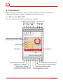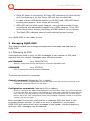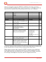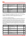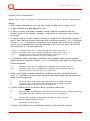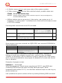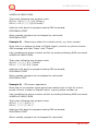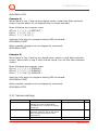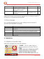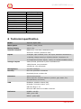
1
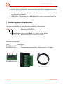
Intelligent power sockets IQsockettm DIN / IQSD-GSM …makes your life more comfortable User Guide IQSD-GSM documentation v1.1.1 R3 User guide www.IQsocket.eu Important information ...................................................................... 3 1 Introduction .................................................................... 4 1.1 Product description ....................................................................... 4 2.1 2.2 2.3 Wiring the IQSD-GSM .................................................................... 6 Inserting SIM Card ........................................................................ 7 Powering IQSD-GSM On................................................................. 7 2 Installation ..................................................................... 6 3 Managing IQSD-GSM ....................................................... 8 This chapter guides you through management commands and features of IQSD-GSM. ....................................................................................... 8 3.1 Managing by SMS ......................................................................... 8 3.2 Managing by phone call ................................................................10 3.3 Timing setup ...............................................................................10 3.4 Date/Time setup ..........................................................................11 3.5 Manual Control ............................................................................11 3.6 Security features .........................................................................12 3.7 Response messages settings .........................................................13 3.8 Scheduler feature ........................................................................14 3.9 Counters .....................................................................................15 3.10 Alarms .....................................................................................15 3.10.1 Defining phone numbers for SMS and ringing up alerts .............16 3.10.2 Battery charge alarm ............................................................16 3.10.3 AC mains power failure alarm ................................................17 3.10.4 Input change alarm (programmable controller mode) ...............17 3.11 Various settings ........................................................................22 3.12 Error messages .........................................................................23 4 Indicators ..................................................................... 23 4.1 4.2 Indication of operation state ..........................................................23 Indication of error state ................................................................24 5.1 5.2 Reset to factory default procedure .................................................24 Factory default settings ................................................................24 6.1 Operation, maintenance and safety recommendations ......................26 5 Factory default settings ................................................ 24 6 Technical specification .................................................. 25 7 Ordering and accessories .............................................. 27 User guide www.IQsocket.eu ©2009 NETCONS, s.r.o. Important information Every effort has been taken to ensure the accuracy of this document, however we do not accept responsibility for damage, injury, loss or expense resulting from errors and omissions, and we reserve the right of amendment without further notice. WARNING: This product is not designed for use in, and should not be used for, medical applications. Product must be mounted on DIN rail (35mm, EN50022), inside a suitable enclosure providing environmental protection. The product contains no serviceable parts, or internal adjustments. No attempt must be made to repair this product. Faulty units must be returned to supplier for repair. This product must be installed by a qualified person. All electrical wiring must be carried out in accordance with the appropriate regulations for the place of installation. Before attempting any electrical connection work, please ensure all supplies are switched off. Page 3 of 27 ©2009 NETCONS, s.r.o. 1 Introduction No one doubt in recent IT world about the fact that communication technologies help us to live our lives easier. There was never such a need of data networking features at products which have had no networking features in the past. Need of data communication in companies even in homes is especially visible in this Internet age. Intelligent power socket IQsocket IQSD-GSM is a member of wide product family of intelligent sockets which helps people to do some tasks remotely. These IQsocket products have following main features: Various communication data interfaces Various number of switched power outputs Various housings to suit particular applications, such as wall-mount style, 19” rack, DIN rail, power socket types for different countries Various inputs / outputs besides switched power outputs 1.1 Product description Intelligent power controller for DIN rail mounting IQsocket IQSD-GSM helps to control any electric appliance remotely over GSM network. IQSD-GSM is managed by SMS messages or phone call. It can work also as a programmable regulator with two independent thermometer inputs, two digital inputs and analogue voltage input, allowing to control an appliance by turning it on/off according to user-defined algorithm/rules. In general, product has following communication features: Sending alarm or informational SMS messages to user Providing status of main/aux switched power output and inputs upon request Sending values of configured parameters upon request Configuring IQSD-GSM parameters simply by sending SMS commands Controlling Main and auxiliary switched outputs by SMS or by call Listening of sound using integrated microphone by call IQsocket IQSD-GSM provides following application features: Control electric appliances over SMS, by call or manually Remotely turnon/turnoff of 230V/10A appliance (main contact output) Remotely turnon/turnoff of 230V100mA appliance (aux contact output) Remotely turnoff or turnon power for specified time Page 4 of 27 ©2009 NETCONS, s.r.o. Remotely reboot appliance by cutting power for a couple seconds (e.g. server restart) Remotely switch of appliance status (turnon to turnoff or back) Remotely measuring of temperature Thermoregulation feature, with custom program definition: o Control outputs based on state of inputs: temperature, digital and voltage input o Notify user by SMS (user defined text or status message) or by making call based on state of inputs Scheduler, based on real time clock o Turnon/turnoff appliances connected via main/aux outputs based on time/day of week Alarm detection – two independent digital inputs: o External detector of motion, gas, fire, water; not included in product package o External detector of opened door, window, shake detector; not included in product package o Any other external detector with contact output can be connected Alarm detection – analogue voltage-sensing input 0-30VDC/0-24VAC: o Measuring of voltage at the input, autosensing if AC or DC o Any external sensor with voltage output can be connected Alarm detection – Input power and backup battery status: o Notifying of AC mains power failure and restoring back o Providing charge status of internal backup Li-Ion battery, including alarm on automatic shutdown due to low battery status. Counters readable by SMS: o 6 independent counters, incrementing when a change occurs on outputs, digital inputs, control button has been pressed and GSM registration has occurred. Monitoring of sound in surrounding environment via integrated microphone Page 5 of 27 ©2009 NETCONS, s.r.o. 2 Installation Before starting installation, please read this manual and take into account Important information section at beginning of this manual. 2.1 Wiring the IQSD-GSM Wire connections per following schematic diagram. Page 6 of 27 ©2009 NETCONS, s.r.o. Note all signals at the bottom terminal block are referenced to the GND pin (#9, most right). Be careful when using any from provided voltage outputs, +12V DC and +4.2VDC outputs are not fused, please respect nominal current ratings of these outputs. Damage caused by overload is not covered by warranty. Please place supplied GSM antenna outside of metal enclosure and keep it away from metal structures which can shield GSM signal. Avoid to run IQSDGSM without antenna connected. Do not power on the 230VC mains voltage yet. 2.2 Inserting SIM Card NOTE: Before SIM is finally used in IQSD-GSM, please turn off PIN authorization. Authorization can be turned off by inserting the SIM card into a GSM phone and disabling SIM PIN usage using appropriate command usually located in „Settings‟ phone menu. Now you can remove the SIM card from phone and insert it into your IQSD-GSM. Insert SIM card with inactive PIN code authorization into the SIM socket bay, accessible from bottom side of IQSD-GSM housing. Push the card into the bay until you feel a click so card is locked inside. To remove the card from IQSD-GSM, gently push the card further into the bay until a click is felt, then card is unlocked and can be pulled out. NOTE: Before using a SIM card in IQSD-GSM, ensure all received SMS messages, stored on the card, are deleted. 2.3 Powering IQSD-GSM On Once the SIM card has been inserted, you can switch on 230VAC mains to power the IQSD-GSM on. Verify device is operating by observing status of the LEDs. Page 7 of 27 ©2009 NETCONS, s.r.o. Once AC power is connected, all three LED indicators will blink shortly and if everything is ok, the Power LED will turn to solid Red. In case of active PIN authorization on the SIM card, GSM LED starts blinking fast (approx. three times per second). GSM LED start to blink slowly (approx. every three seconds) Green, once device was successfully logged into a GSM network. If the LED blinks about every second, searching of GSM network is in progress. The Relay LED indicates state of main switched power contact. Your IQSD-GSM is now ready to use. 3 Managing IQSD-GSM This chapter guides you through management commands and features of IQSD-GSM. 3.1 Managing by SMS Commands are send in form of SMS messages to call number of SIM card inserted into your device. Messages have following syntax: pinCOMMAND (e.g. 3366STATUS) o With pre-configured security password by command SMSPIN=3366 COMMAND (e.g. STATUS) o with un-configured security password/SMSPIN There are two kinds of commands: Control commands (labeled as Ctrl in tables) o Used to control of the IQSD-GSM and can be used at any time. Security settings, such as SMSPIN, permitted callers list, DO apply. Configuration commands (labeled as Cfg in tables) o Allows to configure the IQSD-GSM parameters and functions. Their use is limited by time to 10 minutes after device has been powered on or after last configuration command has been received. Security settings, such as SMSPIN, permitted callers list, DO NOT apply. Device can be put into configuration mode using CONFIG command instead of physically turning it off and on again. Each command is normally confirmed by a response SMS sent back to the command sender number. In case of an error is detected in a command, IQSD-GSM will respond with error message to the sender. Sending response and error SMS messages can be disabled. Page 8 of 27 ©2009 NETCONS, s.r.o. Case of commands is ignored; STATUS or sTaTUS is the same command. All incoming SMS messages longer than 30 characters or messages containing space and dot characters are being deleted without any error response. SMS Command TURNOFF TURNON TURNOFF1 TURNON1 TURNOFF2 TURNON2 TURNOFF=123 TURNON=123 RESTART STATUS RINGON CREDIT*XX# Description Turn off both Main and Aux switched outputs Turn on both Main and Aux switched outputs Turn off Main switched output Turn on Main switched output Turn off Aux switched output Turn on Aux switched output Turn off Main switched output for 123 minutes. Maximum acceptable value is 180 minutes. Turn on Main switched output for 123 minutes. Maximum acceptable value is 180 minutes. Change (negate) status of Main switched output for time preconfigured by command RESTARTTIME. Get status of IQSD-GSM: Outputs, Temperature, digital and voltage inputs, AC mains, Backup Battery charge, time and GSM signal A call-back to the sender‟s number will be made. Useful to keep-alive of credit in prepaid SIM cards. Check remaining credit value of the SIM card, using the same code like dialed on a phone in order to check credit for particular GSM operator, answer of the operator is provided in command response. SMS Response TurnedOff* Type Ctrl TurnedOn* Ctrl TurnedOff1* TurnedOn1* TurnedOff2 TurnedOn2 TurnedOff 123 min* Ctrl Ctrl Ctrl Ctrl Ctrl TurnedOn 123 min* Ctrl Restarted* Ctrl Output:OFF/OFF, Temperature:22.5 C/ NA, Input:OFF/OFF, VoltageIn:0VDC, Bcap: 100%, Power:ON, Time:03/01/01,12:01:25, Signal:76% Ctrl Ctrl YOUR CREDIT IS xxx Ctrl * Commands working with Main switched output cannot be performed during AC power failure. In such case, response to these commands is Command failed. IQSD-GSM use a bistable relay for Main switched output so its state remains unchanged during a power failure. Please ensure a proper code is used for CREDIT command, since entering a wrong code can cause unexpected problems like change settings of the SIM card. IQSD-GSM does not send any error response for the CREDIT command. It is strongly encouraged to verify the code on a regular phone first. Page 9 of 27 ©2009 NETCONS, s.r.o. If a power failure occurs during TURNON=123/ TURNOFF=123 commands, time of power failure is not included in the countdown, so e.g. you need to run an appliance for a hour issuing TURNON=60 command, but AC power is lost after 30minutes and restored back say after 2hours, appliance will be running for half an hour after power is restored back. 3.2 Managing by phone call The Main switched output of IQSD-GSM can be also controlled by dialing the number of its SIM card. Call is for most commands rejected by IQSD-GSM so its use is free of charge, with exception for listening sounds using embedded Microphone. Behavior of IQSD-GSM to incoming calls must be configured in advance using RING command per following table. SMS Command RING=NOACTION RING=RESTART RING=SWITCH RING=MIC RING? Description No action is performed, call is rejected Change (negate) status of Main switched output for time preconfigured by command RESTARTTIME, call is rejected. Change (negate) status of Main switched output, call is rejected. Monitoring of sound in surrounding environment via integrated microphone for one minute, call is answered. Get current configuration of RING action, active setting is in () parentheses. SMS Response RING=NOACTION – OK Type Cfg RING=RESTART – OK Cfg RING=SWITCH – OK Cfg RING=MIC – OK Cfg RING=(NOACTION),RESET Cfg , SWITCH, MIC 3.3 Timing setup Following table summarizes settings of time interval of RESTART command and ringing period used by RINGON command and by alerts by dialing a number under an alarm condition. SMS Command RESTARTTIME=XX RESTARTTIME? RINGONTIME=XX Description Configures time of RESTART command. Range is 1 to 180 seconds. Get current configuration of RESTARTTIME parameter. SMS Response RESTARTTIME=XX – OK Type Cfg RESTARTTIME=10 seconds Cfg Configures how long will IQSD-GSM RINGONTIME=XX – OK keep ringing during a call, initiated by RINGON command or sending alarm alert. Range is 20 to 60 seconds. Cfg Page 10 of 27 ©2009 NETCONS, s.r.o. RINGONTIME? Get current configuration of RINGONTIME parameter. RINGONTIME=30 seconds Cfg 3.4 Date/Time setup IQSD-GSM is equipped with real-time clock, clock is running during a AC power failure until internal backup battery is not empty. There are two ways of date/time setup: Automatic setup based on time stamp of incoming SMS message Manual setup using DATE= command. Enter target time in following format: DATE=yy/mm/dd,hh:mm:ss+zz where zz is Time zone, with either + or - sign. SMS Command DATE Description Date/time is set from timestamp of incoming SMS message DATE=yy/mm/dd,h Set Date/time manually h:mm:ss+zz DATE? Get current settings of Date/time. SMS Response DATE yy/mm/dd,hh:mm:ss+zz – OK DATE=yy/mm/dd,hh:mm: ss+zz – OK DATE yy/mm/dd,hh:mm:ss+zz – OK Type Cfg Cfg Cfg 3.5 Manual Control IQSD-GSM can be controlled manually using push button located in the bottom left corner of front panel, see drawing in section 3.1. Operate button using a suitable narrow tool, e.g. a pen. Main Switched output: Short pressing of the push button will switch state of Main switched output Reset to default settings: By pressing of the push button for longer than 2 seconds but shorter than 5 seconds, all LED indicators start blinking, when the push button is pressed again during LED blinking, IQSD-GSM configuration will be set back to factory default values. Turn Off: Pressing the push button for time longer than 5 seconds, while powered by backup battery (AC mains off), will turn the device off. This is useful e.g. during maintenance or device uninstalling, where device is still running, powered from backup battery, even AC mains power is already switched off. Page 11 of 27 ©2009 NETCONS, s.r.o. Please note commands working with Main switched output, including manual control using the push button, cannot be performed during AC power failure. IQSD-GSM use a bistable relay for Main switched output so its state remains unchanged during a power failure. 3.6 Security features IQSD-GSM is equipped with advanced authorization features to avoid controlling by unauthorized users. The security features include: Allowing control only from authorized phone numbers Authentication of each SMS command by PIN code (SMSPIN) Both features can be used simultaneously. In case of using authorized numbers list, device will ignore all SMS messages and calls received from numbers not included in the permitted phone numbers list. If this security feature is not enabled, device can be controlled by anyone who knows number associated with inserted SIM card. IQSD-GSM allows to define up to 20 permitted phone numbers, each containing up to 15 numerals. In case of using SMSPIN, right before each SMS command is placed PIN code without any space or special character, as shown here: pinCOMMAND (e.g. 3366STATUS) Command will be accepted only when entered PIN code matches with the code predefined by SMSPIN command. NOTE: Pin code (SMSPIN) is having no relation with SIM card PIN code. It is just a password called SMSPIN and used by IQSD-GSM for SMS message authentication, having the same structure as standard PIN = 4 numbers. Security settings can be configured and viewed simply by following commands. SMS Command SECNUMBER=NO SECNUMBER=YES SECNUMBER? SECNUMBER+ 421233355777 Description Security using permitted phone numbers list is turned off/inactive. Security using permitted phone numbers list is turned on/active. Get current configuration of SECNUMBER parameter. Add new number to security list. SMS Response SECNUMBER=NO - OK Type Cfg SECNUMBER=YES - OK Cfg SECNUMBER=(NO),YES Cfg SECNUMBER+421233355 777 - OK Cfg Page 12 of 27 ©2009 NETCONS, s.r.o. SECNUMBER421233355777 SECNUMBER-ALL SECNUMBER=LIST SMSPIN=1234 SMSPIN=NOPIN SMSPIN? Delete specific number from permitted phone numbers list. Delete all numbers from permitted phone numbers list. Get dump of permitted phone numbers list. SECNUMBER421233355777 - OK SECNUMBER-ALL - OK Cfg LIST 421903123456,42190311 1222,421235678235 Or LIST - NO NUMBER! Cfg Configuration of SMS password/SMSPIN. Using of password/SMSPIN is deactivated. Get configuration of SMSPIN parameter. SMSPIN=1234 – OK Cfg SMSPIN=NOPIN – OK Cfg SMSPIN=(NOPIN), 1234 Cfg Cfg Permitted phone numbers list accept only numbers in international format: Example: SECNUMBER+421265440655 means add number +421-2-65440655 Example: SECNUMBER-421265440655 means delete number +421-265440655. 421 is country code in this example and 2 is area code. 3.7 Response messages settings When you communicate with your IQSD-GSM, it is important to make you sure if command was understood and executed successfully. For this purpose we implemented response messages, confirming each command or informing you when an error is detected. In case of SMS commands, you will be notified by back SMS response message. In case of managing IQSD-GSM by phone call, your command will be confirmed by back phone call to your phone number. Note it is not supposed you will answer such back call, you can simply reject it. Configuration commands of response messages settings are summarized in following table. SMS Command SMSCONFIRM=YES SMSCONFIRM=NO SMSCONFIRM? RINGCONFIRM=YES RINGCONFIRM=NO RINGCONFIRM? Description SMS confirmation is enabled/active for all SMS commands SMS confirmation is disabled/inactive for all SMS commands Get configuration of SMSCONFIRM parameter, active setting is in () parentheses. SMS Response SMSCONFIRM=YES - OK Type Cfg SMSCONFIRM=NO - OK Cfg SMSCONFIRM=NO,(YES) Cfg Phone call confirmation is turned on for all commands. Hang off after 10 seconds Phone call confirmation is turned off for all commands Get configuration of RINGCONFIRM parameter, active setting is in () RINGCONFIRM=YES – OK Cfg RINGCONFIRM=NO – OK Cfg RINGCONFIRM=(OFF),ON Cfg Page 13 of 27 ©2009 NETCONS, s.r.o. ERRORREPLY=YES ERRORREPLY=NO ERRORREPLY? parentheses. Sending error SMS messages is enabled/active Sending error SMS messages is disabled/inactive Get configuration of ERRORREPLY parameter, active setting is in () parentheses. ERRORREPLY=YES- OK Cfg ERRORREPLY=NO- OK Cfg ERRORREPLY=NO,(YES) Cfg NOTE: When RINGCONFIRM=YES command is used, realized are confirmation back calls only for SIM cards with active CLIP service. 3.8 Scheduler feature IQSD-GSM is equipped with scheduler, allowing to control Main switched output and to get status message, based on time and day of week. Up to 8 scheduled tasks are supported. Following table summarizes usage of SCHEDULER command. SMS Command Description SCHEDULER+hh:mm Insert scheduler record to execute ,DOW,ACTION particular ACTION at time hh:mm every day of week DOW. SCHEDULER-hh:mm Remove scheduler record for particular time hh:mm SCHEDULER? Get list of all scheduler records. SMS Response SCHEDULER+hh:mm, DOW,ACTION - OK Type Ctrl SCHEDULER-hh:mm - OK Ctrl hh:mm,DOW,ACTION Ctrl Where hh:mm denotes hour and minute of time in 24h format. DOW denotes day of week. Days of week numbers are recognized as follows: 1- Monday, 2-Tuesday, 3-Wednesday, 4 Thursday, 5-Friday, 6-Saturday, 7- Sunday If “*” symbol is inserted, action will be executed daily. If number of day within week is inserted, action will be executed only in the particular day of week. Possible actions are: ON for turning on, OFF for turning off Main switched output, same as TURNON1/TURNOFF1 commands RES for restarting Main switched output, same as RESTART command Page 14 of 27 ©2009 NETCONS, s.r.o. INF, to send STATUS message by SMS to number preconfigured by the ALARMNUMBER command (e.g. ALARMNUMBER+421903123456, see chapter Alarms) Example of SCHEDULER? command output (four actions were recorded): o o o o 11:00,*,ON 14:30,*,OFF 01:30,1,RES 19:00,5,INF Turn on Main switched output every day at 11:00 Turn off Main switched output every day at 14:30 Restart Main switched output every Monday at 01:30 Send Status SMS every Friday at 19:00 3.9 Counters Six independent counters increments their status upon change on IQSD-GSM inputs and outputs. SMS Command COUNTER1? COUNTER2? COUNTER3? COUNTER4? COUNTER5? COUNTER6? COUNTERX? CLEARCOUNTER1 CLEARCOUNTERALL Description Get status of Counter1, increments on change of Digital Input1 Get status of Counter2, increments on change of Digital Input2 Get status of Counter3, increments on change of Main switched output Get status of Counter4, increments on change of Aux switched output Get status of Counter5, increments on pressing of Push Button Get status of Counter6, increments on loosing registration into GSM network Get status of all counters Clear status of counter 1 (2-6) Clear status of all counters SMS Response COUNTER1=0 Type Ctrl COUNTER2=0 Ctrl COUNTER3=0 Ctrl COUNTER4=0 Ctrl COUNTER5=0 Ctrl COUNTER6=0 Ctrl COUNTER=0,0,0,0,0,0 CLEARCOUNTER1- OK CLEARCOUNTERALL- OK Ctrl Ctrl Ctrl Counter1 is incremented by 1 after commands RESTART, TURNOFF, TURNON Highest possible status of a counter is 65535. 3.10 Alarms IQSD-GSM supports three independent alarms. Alarm invoked by change on inputs, having highest priority AC mains power failure alarm Backup battery remaining charge alarm, having lowest priority Page 15 of 27 ©2009 NETCONS, s.r.o. An alarm can generate alert by calling of or sending SMS to up to three predefined phone numbers or in case of alarm invoked by change of inputs, possible alert actions include control of Main switched output and supporting simple scripting allowing IQSD-GSM to act as user-programmable, eventdriven controller. 3.10.1 Defining phone numbers for SMS and ringing up alerts Phone numbers must be entered in international format, see following table. SMS Command ALARMNUMBER+ 421265440655 ALARMNUMBER421265440655 ALARMNUMBER-ALL ALARMNUMBER=LIST Description Add a new number into list for alarm alerts using SMS message and call back. Remove a number from list for alarm alerts using SMS message and call back. Remove all numbers from list for alarm alerts using SMS message and call back. Get list of phone numbers for alarm alerts using SMS message and call back. SMS Response ALARMNUMBER+4212654 40655- OK Type Cfg ALARMNUMBER-4212654 40655- OK Cfg ALARMNUMBER-ALL- OK Cfg LIST 421265440655 Cfg When generating alerts, numbers in list are processed per their order – first number as first, the last number as last. 3.10.2 Battery charge alarm Monitoring remaining charge of IQSD-GSM‟ internal backup battery when AC mains power is temporary failed is easily possible thanks to BATALARM command. You can define up to three battery charge thresholds, given in % of remaining charge. Threshold value can be from 30 to 95 %. Device is automatically switched off once remaining charge falls below 20%. SMS Command BATALARM=30,60,90 BATALARM=00,00,50 BATALARM=00,00,00 BATALARM? Description Send alert SMS every time when remaining battery charge falls below defined thresholds 30,60 and 90%. Send alert SMS every time when remaining battery charge falls below defined threshold 50%. Disable sending remaining battery charge alerts Get configuration of BATALARM SMS Response BATALARM=30,60,90, OK Type Cfg BATALARM=00,00,50, OK Cfg BATALARM=00,00,00, OK Cfg BATALARM=00,00,00 Cfg Page 16 of 27 ©2009 NETCONS, s.r.o. thresholds. Once remaining battery charge reach a predefined threshold, IQSD-GSM will send following SMS alert message to the numbers set by ALARMNUMBER command: Battery! 50% 3.10.3 AC mains power failure alarm IQSD-GSM can send you an SMS alert to inform you when there is a temporary failure of AC mains power for time longer than 10 seconds. Configuration of the power failure alarm is done by using POWERFAULT command. SMS Command POWERFAULT=NO POWERFAULT=INFO POWERFAULT? Description Disable sending alerts when power failed alarm occurs Send alert SMS when power failed alarm occurs – AC mains power fail for time longer than 10 seconds. Get configuration of POWERFAULT parameter, active setting is in () parentheses. SMS Response POWERFAULT=NO, OK Type Cfg POWERFAULT=INFO, OK Cfg POWERFAULT=(NO),INFO Cfg When AC mains fails for time longer than 10 seconds, device will send following SMS alert message to the numbers set by ALARM command: Power failed. In case power is failed for such a long time that charge of internal backup battery falls below 20%, IQSD-GSM will be automatically switched off and following SMS alert message is sent to the numbers set by ALARM command: Low battery shutdown! When AC mains power is restored back, device will send following SMS alert message to the numbers set by ALARM command: Power restored. . NOTE: Commands working with Main switched output cannot be performed during AC power failure. In such case, response to these commands is Command failed. A scheduled action is also not executed. IQSD-GSM use a bistable relay for Main switched output so its state remains unchanged during a power failure. 3.10.4 Input change alarm (programmable controller mode) IQSD-GSM is equipped with following inputs: Two independent thermometer inputs Page 17 of 27 ©2009 NETCONS, s.r.o. Two independent digital inputs to connect various sensors Analogue voltage input to connect various analogue sensors State of all inputs can be read by SMS command STATUS, which returns following SMS message: STATUS SMS Response Output:OFF/OFF, Temperature:22.5 C/ NA, Input:OFF/OFF, VoltageIn:0VDC, Bcap: 100%, Power:ON, Time:03/01/01,12:01:25, Signal:76% Description State of Main and AUX switched outputs State of Temp.Sensor1 (connected) /Temp.Sensor2 (disconnected) State of digital input1/digital input2 State (in [V]) and voltage type (AC or DC) of analogue voltage input Capacity - remaining charge of backup battery State of AC mains power 230VAC (ON/OFF) Current system time and date Current GSM signal strength in % IQSD-GSM supports a simple scripting language that allows to create custom programs, so device will act as event-driven programmable controller. In order to use scripting language, user must know at least basic knowledge of algorithmization. Program is defined in form of row; there can be up to 6 such rows. A program row can be inserted using ID+ command, and removed using IDcommand. Each row consists from identification, evaluation conditions part containing conditions to be evaluated and actions part, each section is separated by comma. Evaluation conditions include besides state of IQSD-GSM inputs also a system variable. Initial value of the variable is set to 0. Value of the variable can be modified in action part of a row executed previously. In order to execute actions part of a row, all the conditions in particular row must be evaluated true. If a condition needs to be skipped/ignored, it can be simply replaced with a star * symbol. Program is processed by rows from left to right and from top to bottom. Once a condition being evaluated is true, evaluation of following condition begins. If a condition being evaluated is false, rest of row is skipped and evaluation continues on following row of the program. Last row is followed in a loop by the first row every second. Page 18 of 27 ©2009 NETCONS, s.r.o. Syntax of ID commands is: IDNr+E_Var,E_Temp1,E_Temp2,E_VoltageIn,DigIn1,DigIn2,A_Alert,A_SetVar,A_Main,SMStext Where IDNr means identification of row with order number Nr in range 1 to 6, + sign indicating to add particular row. E_Var is a value of system variable, which is being compared with the current value of the system variable - evaluation is true when both values are equal. E_Temp1 and E_Temp2 means evaluation condition for Temperature Input 1 and 2, each having syntax beginning with condition symbol (< or >) followed by sign (+ or -) of positive or negative value and by the value itself, having one or two numerals with one decimal place - AB.C or A.B, zero value must be entered as 0.0. Some examples: <+25.5 >+103.5 <-3.7 * condition will be true if input temperature is lower than 25.5 °C condition will be true if input temperature is higher than 103.5 °C condition will be true if input temperature is lower than -3.7 °C evaluation will be ignored, like if it is always true E_VoltageIn means evaluation condition for VoltagIn input, having syntax beginning with condition symbol (< or >) followed by the value in Volts itself. Some examples: <5 >12 * condition will be true if voltage at the VoltageIn input is lower than 5V condition will be true if voltage at the VoltageIn input is higher than 12V evaluation will be ignored, like if it is always true DigIn1 and DigIn2 means evaluation condition for state of Digital Input1 resp. 2 – evaluation is true, when current input state equals to the specified state. Some examples: 1 0 * condition will be true if particular Digital Input is in logical High state condition will be true if particular Digital Input is in logical Low state evaluation will be ignored, like if it is always true A_Alert means action to send an alert, possible values are: S R * SMS message with SMStext content will be sent to all phone numbers predefined by ALARM command. SMStext can contain up to 10 characters. Ringing of all numbers predefined by ALARM command, for time predefined by RINGONTIME command. Represents no Alert action In case of ALARMs were not defined, action A_Alert will be ignored. Page 19 of 27 ©2009 NETCONS, s.r.o. A_SetVar means action to set a new value of the system variable. A_Main means action with the Main switched output, possible values are: TURNON Turn on Main switched output TURNOFF Turn off Main switched output RESTART Change (negate) status of Main switched output for time preconfigured by command RESTARTTIME. SMStext defines text to be sent by A_Alert action, can contain up to 10 characters. If a star symbol * is entered, text of alert will be the same as text of STATUS message. Following table summarizes use of ID command: SMS Command IDLIST Description Get list of all program rows ID+………… Insert a program row, see above for syntax and examples bellow. Delete program row number Nr. IDNr-, OK Nr can be in range from 1 to 6. Delete all program rows. ID0-, OK IDNrID0- SMS Response ID1+0, *,*,*,*,1,*,1,TURNON,* ID2+0, *,*,*,1,*,*,1,TURNON,* ID3+1, *,*,*,0,0,*,0,TURNOFF,* ID+…………., OK Type Ctrl Ctrl Ctrl Ctrl Once program rows were entered into IQSD-GSM, use command PROGRAM to start its execution. SMS Command PROGRAM=START PROGRAM=STOP PROGRAM? Description Start execution of the program Stop execution of the program Get current configuration of PROGRAM, active setting is in () parentheses. SMS Response PROGRAM=START, OK PROGRAM=STOP, OK PROGRAM=(STOP),START Type Ctrl Ctrl Ctrl Please note program is executed in loop with 1s periodicity. Detection of change on inputs with duration shorter than 1 second is then unreliable. Typically 1s periodicity is OK for detection of alarm impulse from a PIR sensor, but it is not recommended to use program for detection of events with shorter than 1s duration. Examples of program scripts: Example 1 – Thermostat When temperature at Temp1 sensor rises beyond 25.5°C, send SMS alert containing STATUS text and switch off Main switched output. When temperature falls bellow 15.1°C, turn the Main switched output on and ring my phone number up. Lets‟ predefine the phone number at first by sending following SMS command: Page 20 of 27 ©2009 NETCONS, s.r.o. ALARM+421903123456 Then enter following two program rows: ID1+0, >25.5,*,*,*,*,S,1,Turnon,* ID2+1,<15.1,*,*,*,*,R,0,Turnoff,* And then let‟s start the program issuing SMS command: PROGRAM=START When needed, program can be stopped by command: PROGRAM=STOP Example 2) – Observing a state of a contact sensor, e.g. door contact Once there is a change of state on Digital Input1, send to my phone number SMS message with text “Open” and “Closed” Lets‟ predefine the phone number at first by sending following SMS command: ALARM+421903123456 Then enter following two program rows: ID1+0, *,*,*,1,*,S,1,*,Closed ID2+1, *,*,*,0,*,S,0,*,Open And then let‟s start the program issuing SMS command: PROGRAM=START When needed, program can be stopped by command: PROGRAM=STOP Example 3) – PIR sensor application Once there is an impulse (input going from steady log1 to log0 for a short period of time) of state on Digital Input2, ring my phone number up. Lets‟ predefine the phone number at first by sending following SMS command: ALARM+421903123456 Then enter following two program rows: ID1+0, *,*,*,*,0,R,1,*,* ID2+1, *,*,*,*,1,*,0,*,* And then let‟s start the program issuing SMS command: PROGRAM=START When needed, program can be stopped by command: Page 21 of 27 ©2009 NETCONS, s.r.o. PROGRAM=STOP Example 4) When there is Log.1 level at both digital inputs, restart the Main switched output (cut the power for an appliance for a couple seconds) Enter following two program rows: ID1+0, *,*,*,1,1,*,1,RESTART,* ID2+1, *,*,*,0,*,*,0,*,* ID3+1, *,*,*,*,0,*,0,*,* And then let‟s start the program issuing SMS command: PROGRAM=START When needed, program can be stopped by command: PROGRAM=STOP Example 5) When there is Log.1 level at any digital input, switch on the Main switched output. When there is Log.0 level at both inputs, turn off the Main switched output. Enter following two program rows: ID1+0, *,*,*,*,1,*,1,TURNON,* ID2+0, *,*,*,1,*,*,1,TURNON,* ID3+1, *,*,*,0,0,*,0,TURNOFF,* And then let‟s start the program issuing SMS command: PROGRAM=START When needed, program can be stopped by command: PROGRAM=STOP 3.11 Various settings SMS Command CONFIG OUTPUT=REMEMBER OUTPUT=NC Description After this command, it is again possible to issue configuration commands, like if device is freshly turned on. When device is powered on, Main switched output is set to the same state as was when device was powered off When device is powered on, Main SMS Response CONFIG, OK Type Ctrl OUTPUT=REMEMBER- OK Cfg OUTPUT=NC- OK Cfg Page 22 of 27 ©2009 NETCONS, s.r.o. OUTPUT=NO OUTPUT? VERSION switched output is in TurnedOn state – contacts C and NC connected When device is powered on, Main switched output is in TurnedOff state – contacts C and NO connected Get configuration of OUTPUT parameter, active setting is in () parentheses. Get firmware version OUTPUT=NO- OK Cfg OUTPUT =(REMEMBER),NC,NO Cfg Ver. 1.1.1 @2009 Ctrl Please note firmware can be currently upgraded only by sending unit back to the factory or to an authorized service center. 3.12 Error messages Error messages are being sent only when sending response messages is permitted (see ERRORREPLY command). SMS response Error! Not allowed! Timeout! Full memory! no number No record Description Incorrect control or configuration command; or wrong SMSPIN In case of permitted phone numbers list is active but used number is not included in it. 10 minutes interval since power on or since last configuration command has timed out. In order to continue using configuration commands, you must either power on the device again or use CONFIG command. Memory for storing permitted phone numbers is full. When trying to get permitted phone number list but the list is empty. When trying to delete non-existing items or records, scheduled tasks or program rows. 4 Indicators 4.1 Indication of operation state IQSD-GSM is equipped with three LED indicators: P OW ER GSM REL A Y POWER – red color, steady lighting is indicating presence of AC mains (230v AC) voltage. GSM – green color, blinking every second indicates searching for a GSM network in progress; blinking every three seconds indicates successful logging into a GSM network. Very fast blinking (about twice per Page 23 of 27 ©2009 NETCONS, s.r.o. second, 0.5s on/0.1s off) indicates an outgoing call in progress, e.g. a ringing alert in case of alarm or during RINGON command. RELAY – yellow color, indicates state of Main switched output relay: steady lighting means turned on - connected contacts C and NO; not lighting means turned off – connected contacts C and NC. 4.2 Indication of error state POWER – red color, blinking fast about twice per second indicated SIM card is not inserted. When battery is deeply discharged (voltage under 3.65V), charging process will start, which is indicated by slow blinking (1.5sec on/ 0.1sec off). When battery reaches usable voltage (3.75V), GSM module is powered on and device is fully enabled. GSM – green color, blinking fast about twice per second indicates SIM card with active PIN authorization. It is necessary to disable the PIN authorization using a GSM phone. RELAY – yellow, blinking fast indicated a HW failure. 5 Factory default settings Each device come from factory preconfigured with factory default values. Device can be anytime returned back to these default values by using reset to factory defaults procedure. 5.1 Reset to factory default procedure Reset is done by pushing the push button located in bottom left corner at the front panel. See also chapter 3.5. By pressing of the push button for longer than 2 seconds but shorter than 5 seconds, all LED indicators start blinking, when the push button is pressed again during LED blinking, IQSD-GSM configuration will be set back to factory default values. After this step is your device in original factory configuration. BE CAREFULL! This step will erase all your IQsocket configuration. 5.2 Factory default settings Page 24 of 27 ©2009 NETCONS, s.r.o. Parameter RING RESTARTTIME RINGONTIME SMSPIN SECNUMBER SMSCONFIRM RINGCONFIRM ERRORREPLY BATALARM POWERFAULT PROGRAM OUTPUT Default setting NOACTION 10 30 NOPIN NO YES NO YES 00,00,00 NO STOP REMEMBER 6 Technical specification Model IQsocket IQSD-GSM Mains power 230VAC / 50Hz, 15mA Backup battery 4.2V Li-Ion Switched Outputs MAIN 230V, 10A max (resistance load) AUX 230V 100mA (resistance load) Inputs 2x Digital, optic-isolated, max. 30V input, detection threshold 1V 1x Analog voltage sensing 0-30VDC/0-24VAC. Resolution 1V 2x Temperature sensor inputs, 1-Wire, for Dallas DS18B20 sensor Voltage outputs 5VDC/100mA, protected by auto-resettable fuse 12VDC/80mA, non-protected! 4.2VDC/1A, non-protected! Management Via SMS messages Security PIN code protected commands Permitted phone numbers list Detectors Inbuilt thermometer Alarm input for external detectors (motion, gas, water, fire, door/Windows, and more.) GSM EGSM900, GSM850 Class4 (2W) DCS1800, PCS1900 Class1 (1W) SIM card Plug-in 3V External 2dBi antenna via SMA connector Indicators POWER: red LED GSM: green LED RELAY: yellow LED Page 25 of 27 ©2009 NETCONS, s.r.o. Features Dimensions Appliance control over SMS, by call or manually Remote restart of appliances Temperature monitoring Digital sensors monitoring Analogue sensor monitoring Programmable event-driven controller Alarm detection Monitoring of sound using integrated microphone 90x53x58mm Weight 0.1kg netto Operating temperature 0 to +50 ˚C Humidity Max. 80%, non-condensing Operating temperature 0 to +50 ˚C Mounting DIN rail (35mm, EN50022), 3 modules wide Compliance CE 6.1 Operation, maintenance and safety recommendations Do not modify product in any way and do not operate product modified any way. Warranty is void when product was disassembled or modified in any way. Product is not fused; ensure it is installed in fused electric installation only. Product is not intended as security device, alarm functions are just auxiliary. Product can be operated only indoor office/house environment. Do not expose it to humid, wet nor chemically aggressive environment. Product is not designed for industrial operation with aggressive environment. Before use, please check, if mobile phones can be used in the area. In not, please don‟t put product into operation, it can have negative influence to other electronic systems. Don‟t expose product to vibrations, shaking or fall downs to avoid product damage. When use sound monitoring for taping purposes, ensure you have prior permission to do it from affected people. Load current 10A/0.1A is valid for resistive load. If you need to switch an non-resistive or higher current load, use an external contactor rated for target load among the product. Switching a non-resistive load or higher than nominal rating currents can cause permanent damage of switching elements, which is not covered by warranty. Page 26 of 27 ©2009 NETCONS, s.r.o. Before using a SIM card, ensure all received SMS messages stored on the card are deleted. Product is not a toy for children, SIM card represents a small part that can be easily ingested. WARNING: This product is not designed for use in, and should not be used for, medical applications. 7 Ordering and accessories IQsocket product family uses following ordering code system: IQSx-y-z Example: IQSD-GSM Product family: W=WALL | R=RACK | D=DIN Product model: GSM | IP | RS232 | HDO | IPGSM Output Socket type: F=Schuko | E=French Optional accessories Code Description TEMPDIN1820DPS PCB with temperature sensor TEMPDIN1820A Temperature sensor with metal housing, 1m cable TEMPDIN1820DPS Detail of installation TEMPDIN1820A Page 27 of 27