1
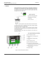
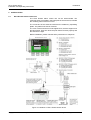
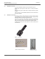
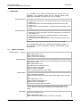
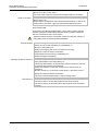
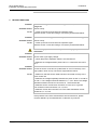
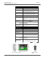
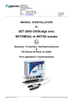
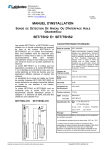
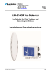
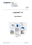
Labkotec Oy
Myllyhaantie 6
FI-33960 PIRKKALA
FINLAND
Tel:
+ 358 29 006 260
Fax:
+ 358 29 006 1260
Internet: www.labkotec.fi
19.1.2015
D15623Ce
1/11
GA-2
Grease Separator Alarm Device
with two sensors
Installation and Operating Instructions
Copyright © 2015 Labkotec Oy
We reserve the right for changes without notice
GA-2 Grease Alarm
Installation and Operating Instructions
D15623Ce
TABLE OF CONTENTS
1 GENERAL ............................................................................................................ 3
2 INSTALLATION ................................................................................................... 4
2.1 GA-2 Grease Alarm control unit ................................................................... 4
2.2 Installation of sensors .................................................................................. 5
2.3 Installation accessories ................................................................................ 5
3 OPERATION ........................................................................................................ 6
3.1 Mode of operation ........................................................................................ 6
4 TROUBLE-SHOOTING ....................................................................................... 8
5 REPAIR AND SERVICE ...................................................................................... 9
6 SAFETY INSTRUCTIONS ................................................................................... 9
7 TECHNICAL DATA ............................................................................................ 10
SYMBOLS
Warning / Attention
Device is protected by double or reinforced insulation
Copyright © 2015 Labkotec Oy
2/11
We reserve the right for changes without notice
GA-2 Grease Alarm
Installation and Operating Instructions
1
D15623Ce
GENERAL
GA-2 Grease Alarm is an alarm device for monitoring the thickness of
the grease layer accumulating in the grease separator and blocking of
the separator. The delivery consists of GA-2 Grease Alarm control unit,
two similar GA-SG1 sensors, which are used as grease alarm and
blockage sensors and cable joint.
Figure 1. Grease separator alarm system with GA-2 Grease Alarm
The grease alarm sensor is installed into the grease storage chamber
and supervises thickness of grease layer.
The blockage sensor is installed above the grease storage chamber
and supervises the total liquid level of the separator and gives an alarm
from possible blockage
The LED indicators, push button and interfaces of the device are
described in figure 2.
Figure 2. GA-2 Grease Alarm –features
Copyright © 2015 Labkotec Oy
3/11
We reserve the right for changes without notice
GA-2 Grease Alarm
Installation and Operating Instructions
2
2.1
D15623Ce
INSTALLATION
GA-2 Grease Alarm control unit
The GA-2 Grease Alarm control unit can be wall-mounted. The
mounting holes are located in the base plate of the enclosure, beneath
the mounting holes of the front cover.
The connectors of the external conductors are isolated by separating
plates. The plates must not be removed.
The cover of the enclosure must be tightened so, that the edges touch
the base frame. Only then does the push button function properly and
the enclosure is tight.
Before installation, please read the safety instructions in chapter 6!
Figure 3. Installation of GA-2 Grease Alarm device.
Copyright © 2015 Labkotec Oy
4/11
We reserve the right for changes without notice
GA-2 Grease Alarm
Installation and Operating Instructions
2.2
D15623Ce
Installation of sensors
The sensor installation should be done as described in figure 3.
Grease alarm sensor gives an alarm when it is wholly immersed in
grease.
Blockage sensor gives an alarm when it is wholly immersed in grease
or water.
Please check the correct installation depth also from the instructions of
the grease separator.
2.3
Installation accessories
The delivery includes a cable joint (figure 4), fixing accessories (figure
5) for installation of the control unit and the sensor. In figure 6 is an
installation example of cable with suspension hook.
Connections of the sensor cable inside the cable joint are explained in
figure 3. If shielded cable is used cable shields and possible excess
wires need to be connected to the same point in galvanic contact.
IP rating of the cable joint is IP68. Make sure, that the cable joint is
closed properly.
Figure 4. Cable joint
Figure 5. Fixing accessories
Copyright © 2015 Labkotec Oy
5/11
Figure 6. Cable
installation example
We reserve the right for changes without notice
GA-2 Grease Alarm
Installation and Operating Instructions
3
D15623Ce
OPERATION
The operation of the device should always be checked after the
installation. The operation should also be checked always when
emptying the separator or at least once every six months.
Functionality test
Blockage alarm
1. Lift the sensor up in the air. The device should be in normal mode (see
chapter 3.1).
2. Immerse the sensor into water. Blockage alarm should occur (see
chapter 3.1).
3. Lift the sensor up in the air again. The alarm should go off after 10 sec
delay.
Functionality test
Grease alarm
1. Immerse the sensor into water. The device should be in normal mode
(see chapter 3.1).
2. Lift the sensor up in the air or immerse into grease. Grease alarm
should occur. (see chapter 3.1).
3. Immerse the sensor back into water. Alarm should go off after 10 sec
delay.
Clean up the sensors before placing them back into the separator.
A more detailed description of the operation is provided in chapter 3.1.
If the operation is not as described, contact a representative of the
manufacturer.
3.1
Mode of operation
Normal mode – no alarms
Grease alarm sensor is totally in water and blockage sensor is in the air.
Mains LED indicator is on.
Other LED indicators are off.
Relays 1 and 2 are energized.
Blockage alarm
The level has hit the blockage sensor. (Sensor gives an alarm earliest
when level is on the middle of sensor and latest when the sensor is wholly
immersed in liquid.)
Mains LED indicator is on.
Blockage alarm LED indicator is on.
Buzzer on after 10 sec delay.
Relay 2 remains energized.
Relay 1 de-energizes after 10 sec delay.
Grease alarm
Grease alarm sensor is in grease. (Sensor gives an alarm latest when it is
wholly immersed in grease.)
(Note! The same alarm takes place when grease alarm sensor is in the
air)
Mains LED indicator is on.
Grease alarm LED indicator is on.
Buzzer on after 10 sec delay.
Relay 2 de-energizes after 5 sec delay.
After removal of an alarm, the respective alarm LED indicators and
buzzer will be off and respective relay will be energized after 10 sec
delay.
Fault alarm
Copyright © 2015 Labkotec Oy
A broken sensor, sensor cable break or short circuit, i.e. too low or too
high sensor signal current.
Mains LED indicator is on.
Sensor circuit Fault LED indicator is on after 10 sec delay.
6/11
We reserve the right for changes without notice
GA-2 Grease Alarm
Installation and Operating Instructions
D15623Ce
Buzzer is on after 10 sec delay.
The relay of the respective channel de-energizes after 10 sec delay.
Reset of an alarm
When pressing the Reset push button.
Buzzer will go off.
Relays will not change their status before the actual alarm or fault is off.
If the buzzer is not reset, it goes off automatically after three days.
TEST FUNCTION
Test function provides an artificial alarm, which can be used to test the
function of the GA-2 Grease Alarm and the function of other equipment,
which is connected to GA-2 via its relays.
Attention! Before pressing Test button, make sure that the change of
relay status does not cause hazards elsewhere!
Normal situation
When pressing the Test push button:
Alarm and Fault LED indicators are immediately on.
Buzzer is immediately on.
Relays de-energize after 2 sec of continuous pressing.
When the Test push button is released:
LED indicators and buzzer go immediately off.
Relays energize immediately.
Blockage or Grease alarm on
When pressing the Test push button:
Fault LED indicators are immediately on.
The Alarm LED indicator of the alarming channel remains on and the
respective relay remains de-energised.
Alarm LED indicator of the other channel is on and the relay deenergizes.
Buzzer remains on. If it has been reset earlier, it will return to be on.
When the Test push button is released:
The device returns without delay to the preceding status.
Fault alarm on
Copyright © 2015 Labkotec Oy
When pressing Test push button:
The device does not react with regards to the faulty channel.
The device reacts as described above with regards to the functional
channel.
7/11
We reserve the right for changes without notice
GA-2 Grease Alarm
Installation and Operating Instructions
4
D15623Ce
TROUBLE-SHOOTING
Problem:
Possible reason:
To do:
Problem:
Possible reason:
To do:
No alarm when grease alarm sensor in grease or air, or the alarm will
not go off
Sensor is dirty.
1. Clean-up the sensor and check the operation again.
Measure sensor current and voltage, if necessary as described below.
No alarm when blockage sensor in liquid, or the alarm will not go off
Sensor is dirty.
1. Clean-up the sensor and check the operation again.
Measure sensor current and voltage, if necessary as described below.
The following operations must be performed only by a qualified
electrician!
Problem:
Possible reason:
To do:
MAINS LED indicator is off
Device doesn’t get supply voltage.
1. Check that power separation switch is not switched off.
2. Measure the voltage between poles N and L1. It should be 230 VAC ±
10 %.
Problem:
FAULT LED indicator is on
Possible reason:
Current in sensor circuit too low (cable break or out of connector) or too
high (cable in short circuit). The sensor might also be broken.
To do:
1. Make sure, that the sensor cable has been connected correctly to the
GA-2 control unit.
2. Measure the voltage separately between the poles 10 and 11 as well as
13 and 14. The voltages should be between 7,0 - 8,5 V. Note! The voltage
alternates between the sensor connectors in 1 second intervals.
3. Measure sensor current when the sensor is in the air or in grease.
The measured current should be 7,0 – 8,5 mA.
4. Measure current when the sensor is in the water. Measured current
should be 2,5 – 3,5 mA
If the problems can not be solved with the above instructions, please
contact Labkotec Oy’s local distributor or Labkotec Oy’s service.
Copyright © 2015 Labkotec Oy
8/11
We reserve the right for changes without notice
GA-2 Grease Alarm
Installation and Operating Instructions
5
D15623Ce
REPAIR AND SERVICE
The sensors should be cleaned and the operation of the alarm device
should be tested when emptying or maintaining the grease separator or
at least once every six months. For cleaning, a mild detergent (e.g.
washing-up liquid) and a scrubbing brush can be used.
In case of queries, please contact Labkotec Oy’s service:
[email protected].
6
SAFETY INSTRUCTIONS
The device does not include a mains switch. A two pole mains switch
(250 VAC 1 A), which isolates both lines (L1, N) must be installed in the
main power supply lines in the vicinity of the unit. This switch facilitates
maintenance and service operations and it has to be marked to identify
the unit.
If opening of housing’s cover is needed, only an authorized electrician
is allowed to install or to maintain the device.
If the device is used against the manufacturer’s instructions, the
protection provided by the device may be damaged.
The device is not allowed to install in hazardous areas.
Copyright © 2015 Labkotec Oy
9/11
We reserve the right for changes without notice
GA-2 Grease Alarm
Installation and Operating Instructions
D15623Ce
7 TECHNICAL DATA
GA-2 control unit
Dimensions
125 mm x 75 mm x 35 mm (l x h x d)
Weight
250 g
Package 1,2 kg (control unit + 2 sensors + cable joint)
Enclosure
IP 65, material polykarbonate
Cable glands adjustment range is 6 – 10mm
Operation temperature
-30 ºC…+50 ºC
Supply voltage
230 VAC ± 10 %, 50/60 Hz
The device is not equipped with a mains switch.
Power consumption
5 VA
Sensors
2 pcs GA-SG1 sensors
Relay output
2 pcs potential-free relay outputs
250 V, 5 A
Operational delay 10 sec. Relay de-energize at trigger
point.
Electrical safety
IEC/EN 61010-1, Class II
, CAT II
EMC
Emission
Immunity
Manufacturing year:
Please see the serial
number on the type plate
IEC/EN 61000-6-3
IEC/EN 61000-6-1
xxx x xxxxx xx YY x
where YY = manufacturing year
(e.g. 14 = 2014)
GA-SG1 sensor
Principle of operation
Capacitive
Material
POM, PUR, AISI 316
Weight
350 g (sensor + fixed cable)
IP-classification
IP68
Operation temperature
0 ºC…+90 ºC
Cable
Fixed cable 2 x 0,75 mm2. Standard length 5 m, other
lengths optional. The max. length of the fixed cable is
15 m, can be extended. Maximum cable loop resistance
is 75Ω.
EMC
Emission
Immunity
IEC/EN 61000-6-3
IEC/EN 61000-6-1
Manufacturing year:
GAxxxxxYY
Please see the serial
number from the bottom of
sensor
where YY = manufacturing year (e.g. 14 = 2014)
Figure 7. GA-2 control unit
Copyright © 2015 Labkotec Oy
Figure 8. GA-SG1
sensor
10/11
We reserve the right for changes without notice