1
ORTEC
®
digiDART ®
Portable HPGe MCA
Operator Manual
Printed in U.S.A.
ORTEC® Part No. 783610
Manual Revision F
0210
Advanced Measurement Technology, Inc.
a/k/a/ ORTEC®, a subsidiary of AMETEK®, Inc.
WARRANTY
ORTEC* warrants that the items will be delivered free from defects in material or workmanship. ORTEC makes no
other warranties, express or implied, and specifically NO WARRANTY OF MERCHANTABILITY OR FITNESS
FOR A PARTICULAR PURPOSE.
ORTEC’s exclusive liability is limited to repairing or replacing at ORTEC’s option, items found by ORTEC to be
defective in workmanship or materials within one year from the date of delivery. ORTEC’s liability on any claim of
any kind, including negligence, loss, or damages arising out of, connected with, or from the performance or breach
thereof, or from the manufacture, sale, delivery, resale, repair, or use of any item or services covered by this
agreement or purchase order, shall in no case exceed the price allocable to the item or service furnished or any part
thereof that gives rise to the claim. In the event ORTEC fails to manufacture or deliver items called for in this
agreement or purchase order, ORTEC’s exclusive liability and buyer’s exclusive remedy shall be release of the buyer
from the obligation to pay the purchase price. In no event shall ORTEC be liable for special or consequential
damages.
Quality Control
Before being approved for shipment, each ORTEC instrument must pass a stringent set of quality control tests
designed to expose any flaws in materials or workmanship. Permanent records of these tests are maintained for use
in warranty repair and as a source of statistical information for design improvements.
Repair Service
If it becomes necessary to return this instrument for repair, it is essential that Customer Services be contacted in
advance of its return so that a Return Authorization Number can be assigned to the unit. Also, ORTEC must be
informed, either in writing, by telephone [(865) 482-4411] or by facsimile transmission [(865) 483-2133], of the
nature of the fault of the instrument being returned and of the model, serial, and revision ("Rev" on rear panel)
numbers. Failure to do so may cause unnecessary delays in getting the unit repaired. The ORTEC standard procedure
requires that instruments returned for repair pass the same quality control tests that are used for new-production
instruments. Instruments that are returned should be packed so that they will withstand normal transit handling and
must be shipped PREPAID via Air Parcel Post or United Parcel Service to the designated ORTEC repair center. The
address label and the package should include the Return Authorization Number assigned. Instruments being returned
that are damaged in transit due to inadequate packing will be repaired at the sender's expense, and it will be the
sender's responsibility to make claim with the shipper. Instruments not in warranty should follow the same procedure
and ORTEC will provide a quotation.
Damage in Transit
Shipments should be examined immediately upon receipt for evidence of external or concealed damage. The carrier
making delivery should be notified immediately of any such damage, since the carrier is normally liable for damage
in shipment. Packing materials, waybills, and other such documentation should be preserved in order to establish
claims. After such notification to the carrier, please notify ORTEC of the circumstances so that assistance can be
provided in making damage claims and in providing replacement equipment, if necessary.
Copyright © 2010, Advanced Measurement Technology, Inc. All rights reserved.
*ORTEC® is a registered trademark of Advanced Measurement Technology, Inc. All other trademarks used
herein are the property of their respective owners.
ADDITIONAL WARRANTY STATEMENT
Please note that the digiDART contains no user-serviceable parts.
Breaking the seal on the case voids your warranty. The digiDART should
be opened only by ORTEC-authorized service personnel.
iii
iv
TABLE OF CONTENTS
Installation: Page 27
Menu Quick-Reference: Page 116
WARRANTY . . . . . . . . . . . . . . . . . . . . . . . . . . . . . . . . . . . . . . . . . . . . . . . . . . . . . . . . . . . . . . . . ii
1. INTRODUCTION . . . . . . . . . . . . . . . . . . . . . . . . . . . . . . . . . . . . . . . . . . . . . . . . . . . . . . . . . .
1.1. How the digiDART Collects and Stores Spectra . . . . . . . . . . . . . . . . . . . . . . . . . . . . . .
1.1.1. Live Spectrum . . . . . . . . . . . . . . . . . . . . . . . . . . . . . . . . . . . . . . . . . . . . . . . . . . . .
1.1.2. Stored-Spectrum Memory . . . . . . . . . . . . . . . . . . . . . . . . . . . . . . . . . . . . . . . . . .
1.2. Host PC and Software Requirements . . . . . . . . . . . . . . . . . . . . . . . . . . . . . . . . . . . . . . .
1
2
2
2
4
2. THE DIGIDART . . . . . . . . . . . . . . . . . . . . . . . . . . . . . . . . . . . . . . . . . . . . . . . . . . . . . . . . . . . 5
2.1. Display and Keypad . . . . . . . . . . . . . . . . . . . . . . . . . . . . . . . . . . . . . . . . . . . . . . . . . . . . . 5
2.1.1. The Display . . . . . . . . . . . . . . . . . . . . . . . . . . . . . . . . . . . . . . . . . . . . . . . . . . . . . . 5
2.1.2. Keypad . . . . . . . . . . . . . . . . . . . . . . . . . . . . . . . . . . . . . . . . . . . . . . . . . . . . . . . . . 6
2.2. Menu Commands . . . . . . . . . . . . . . . . . . . . . . . . . . . . . . . . . . . . . . . . . . . . . . . . . . . . . . . 9
2.2.1. (1) View Status . . . . . . . . . . . . . . . . . . . . . . . . . . . . . . . . . . . . . . . . . . . . . . . . . . 10
2.2.2. (2) Enter ID . . . . . . . . . . . . . . . . . . . . . . . . . . . . . . . . . . . . . . . . . . . . . . . . . . . . . 10
2.2.3. (3) Nuclide ROIs . . . . . . . . . . . . . . . . . . . . . . . . . . . . . . . . . . . . . . . . . . . . . . . . 11
2.2.4. (4) Status Line . . . . . . . . . . . . . . . . . . . . . . . . . . . . . . . . . . . . . . . . . . . . . . . . . . 12
2.2.5. (5) Peak Info . . . . . . . . . . . . . . . . . . . . . . . . . . . . . . . . . . . . . . . . . . . . . . . . . . . . 12
2.2.6. (6) Adjust Controls . . . . . . . . . . . . . . . . . . . . . . . . . . . . . . . . . . . . . . . . . . . . . . . 13
2.2.6.1. HV Settings . . . . . . . . . . . . . . . . . . . . . . . . . . . . . . . . . . . . . . . . . . . . . 13
2.2.6.2. Amplifier Settings . . . . . . . . . . . . . . . . . . . . . . . . . . . . . . . . . . . . . . . . 14
2.2.6.3. Preset Settings . . . . . . . . . . . . . . . . . . . . . . . . . . . . . . . . . . . . . . . . . . . 16
2.2.6.4. ADC Settings . . . . . . . . . . . . . . . . . . . . . . . . . . . . . . . . . . . . . . . . . . . . 20
2.2.6.5. Stabilizer Settings . . . . . . . . . . . . . . . . . . . . . . . . . . . . . . . . . . . . . . . . 21
2.2.7. (7) General Settings . . . . . . . . . . . . . . . . . . . . . . . . . . . . . . . . . . . . . . . . . . . . . . 22
2.2.8. (8) Spectrum Memory . . . . . . . . . . . . . . . . . . . . . . . . . . . . . . . . . . . . . . . . . . . . 24
2.2.9. (9) Nuclide Report . . . . . . . . . . . . . . . . . . . . . . . . . . . . . . . . . . . . . . . . . . . . . . . 26
3. INSTALLATION AND STARTUP . . . . . . . . . . . . . . . . . . . . . . . . . . . . . . . . . . . . . . . . . . . .
3.1. Software and Hardware Installation . . . . . . . . . . . . . . . . . . . . . . . . . . . . . . . . . . . . . . .
3.1.1. Install MAESTRO-32 and the CONNECTIONS-32 Driver Update Kit . . . . . . . .
3.1.2. Connect the digiDART to the USB Port on the PC . . . . . . . . . . . . . . . . . . . . . .
3.1.3. Run the MCB Configuration Program to Build a List of Available Detectors .
3.1.4. Attaching More Than One digiDART to the PC . . . . . . . . . . . . . . . . . . . . . . . .
3.1.5. Connecting to and Disconnecting from the PC . . . . . . . . . . . . . . . . . . . . . . . . .
27
27
27
27
27
27
28
v
digiDART® Portable HPGe MCA User’s Manual
3.2. Cabling . . . . . . . . . . . . . . . . . . . . . . . . . . . . . . . . . . . . . . . . . . . . . . . . . . . . . . . . . . . . . . 28
3.3. Turning the Power On and Off . . . . . . . . . . . . . . . . . . . . . . . . . . . . . . . . . . . . . . . . . . . 29
3.4. Changing the Battery . . . . . . . . . . . . . . . . . . . . . . . . . . . . . . . . . . . . . . . . . . . . . . . . . . . 29
4. USING THE DIGIDART IN FIELD MODE . . . . . . . . . . . . . . . . . . . . . . . . . . . . . . . . . . . . .
4.1. Normal Operation . . . . . . . . . . . . . . . . . . . . . . . . . . . . . . . . . . . . . . . . . . . . . . . . . . . . .
4.1.1. Battery . . . . . . . . . . . . . . . . . . . . . . . . . . . . . . . . . . . . . . . . . . . . . . . . . . . . . . . . .
4.1.2. Detector . . . . . . . . . . . . . . . . . . . . . . . . . . . . . . . . . . . . . . . . . . . . . . . . . . . . . . .
4.1.3. Stored Spectrum Memory . . . . . . . . . . . . . . . . . . . . . . . . . . . . . . . . . . . . . . . . . .
4.1.4. Spectrum Status Parameters . . . . . . . . . . . . . . . . . . . . . . . . . . . . . . . . . . . . . . . .
4.1.5. ADC . . . . . . . . . . . . . . . . . . . . . . . . . . . . . . . . . . . . . . . . . . . . . . . . . . . . . . . . . .
4.1.6. Amplifier . . . . . . . . . . . . . . . . . . . . . . . . . . . . . . . . . . . . . . . . . . . . . . . . . . . . . . .
4.1.7. Rise Time and Flattop . . . . . . . . . . . . . . . . . . . . . . . . . . . . . . . . . . . . . . . . . . . .
4.1.8. Optimize . . . . . . . . . . . . . . . . . . . . . . . . . . . . . . . . . . . . . . . . . . . . . . . . . . . . . . .
4.1.9. Detector State of Health . . . . . . . . . . . . . . . . . . . . . . . . . . . . . . . . . . . . . . . . . . .
4.1.10. Calibration . . . . . . . . . . . . . . . . . . . . . . . . . . . . . . . . . . . . . . . . . . . . . . . . . . . .
4.1.11. Display Energy . . . . . . . . . . . . . . . . . . . . . . . . . . . . . . . . . . . . . . . . . . . . . . . . .
4.1.12. Setting ROIs in the Spectrum Display . . . . . . . . . . . . . . . . . . . . . . . . . . . . . . .
4.1.13. Presets . . . . . . . . . . . . . . . . . . . . . . . . . . . . . . . . . . . . . . . . . . . . . . . . . . . . . . . .
4.1.14. Stabilizers . . . . . . . . . . . . . . . . . . . . . . . . . . . . . . . . . . . . . . . . . . . . . . . . . . . . .
4.1.15. Nuclide Report . . . . . . . . . . . . . . . . . . . . . . . . . . . . . . . . . . . . . . . . . . . . . . . . .
4.1.16. Administrator and User Passwords . . . . . . . . . . . . . . . . . . . . . . . . . . . . . . . . .
4.1.17. Locking the Spectrum Display . . . . . . . . . . . . . . . . . . . . . . . . . . . . . . . . . . . . .
4.1.18. Collecting Spectra . . . . . . . . . . . . . . . . . . . . . . . . . . . . . . . . . . . . . . . . . . . . . .
4.1.19. Downloading Spectra to the PC . . . . . . . . . . . . . . . . . . . . . . . . . . . . . . . . . . . .
4.2. Should You Take a Laptop Into the Field? . . . . . . . . . . . . . . . . . . . . . . . . . . . . . . . . . .
4.2.1. Operation with a PC . . . . . . . . . . . . . . . . . . . . . . . . . . . . . . . . . . . . . . . . . . . . . .
4.3. Troubleshooting . . . . . . . . . . . . . . . . . . . . . . . . . . . . . . . . . . . . . . . . . . . . . . . . . . . . . . .
4.3.1. If You Disconnected While In InSight Virtual Oscilloscope Mode . . . . . . . . .
4.3.2. The digiDART Will Not Turn on . . . . . . . . . . . . . . . . . . . . . . . . . . . . . . . . . . . .
4.3.3. If You Forgot the Password . . . . . . . . . . . . . . . . . . . . . . . . . . . . . . . . . . . . . . . .
4.3.4. MAESTRO Does Not Connect with the digiDART . . . . . . . . . . . . . . . . . . . . .
31
31
31
32
32
32
33
33
34
34
34
35
36
36
36
37
37
37
39
40
41
41
41
42
42
42
42
42
5. USING THE DIGIDART WITH MAESTRO . . . . . . . . . . . . . . . . . . . . . . . . . . . . . . . . . . . .
5.1. Amplifier Tab . . . . . . . . . . . . . . . . . . . . . . . . . . . . . . . . . . . . . . . . . . . . . . . . . . . . . . . . .
5.2. Amplifier 2 Tab . . . . . . . . . . . . . . . . . . . . . . . . . . . . . . . . . . . . . . . . . . . . . . . . . . . . . . .
5.3. ADC Tab . . . . . . . . . . . . . . . . . . . . . . . . . . . . . . . . . . . . . . . . . . . . . . . . . . . . . . . . . . . .
5.4. Stabilizer Tab . . . . . . . . . . . . . . . . . . . . . . . . . . . . . . . . . . . . . . . . . . . . . . . . . . . . . . . . .
5.5. High Voltage Tab . . . . . . . . . . . . . . . . . . . . . . . . . . . . . . . . . . . . . . . . . . . . . . . . . . . . . .
5.6. Field Data Tab . . . . . . . . . . . . . . . . . . . . . . . . . . . . . . . . . . . . . . . . . . . . . . . . . . . . . . . .
5.7. About Tab . . . . . . . . . . . . . . . . . . . . . . . . . . . . . . . . . . . . . . . . . . . . . . . . . . . . . . . . . . . .
43
43
45
46
47
48
49
50
vi
TABLE OF CONTENTS
5.8. Status Tab . . . . . . . . . . . . . . . . . . . . . . . . . . . . . . . . . . . . . . . . . . . . . . . . . . . . . . . . . . . .
5.9. Presets Tab . . . . . . . . . . . . . . . . . . . . . . . . . . . . . . . . . . . . . . . . . . . . . . . . . . . . . . . . . . .
5.10. MDA Preset Tab . . . . . . . . . . . . . . . . . . . . . . . . . . . . . . . . . . . . . . . . . . . . . . . . . . . . .
5.11. Nuclide Report Tab . . . . . . . . . . . . . . . . . . . . . . . . . . . . . . . . . . . . . . . . . . . . . . . . . . .
5.11.1. Add New . . . . . . . . . . . . . . . . . . . . . . . . . . . . . . . . . . . . . . . . . . . . . . . . . . . . . .
5.11.1.1. Manual Add . . . . . . . . . . . . . . . . . . . . . . . . . . . . . . . . . . . . . . . . . . . .
5.11.1.2. Library Add . . . . . . . . . . . . . . . . . . . . . . . . . . . . . . . . . . . . . . . . . . . .
5.11.2. Edit . . . . . . . . . . . . . . . . . . . . . . . . . . . . . . . . . . . . . . . . . . . . . . . . . . . . . . . . . .
5.11.3. Delete . . . . . . . . . . . . . . . . . . . . . . . . . . . . . . . . . . . . . . . . . . . . . . . . . . . . . . . .
50
53
54
55
56
56
56
56
56
6. CALCULATIONS . . . . . . . . . . . . . . . . . . . . . . . . . . . . . . . . . . . . . . . . . . . . . . . . . . . . . . . . .
6.1. The Nuclide Report . . . . . . . . . . . . . . . . . . . . . . . . . . . . . . . . . . . . . . . . . . . . . . . . . . . .
6.1.1. Calculations . . . . . . . . . . . . . . . . . . . . . . . . . . . . . . . . . . . . . . . . . . . . . . . . . . . .
6.2. MDA Preset Calculation . . . . . . . . . . . . . . . . . . . . . . . . . . . . . . . . . . . . . . . . . . . . . . . .
6.3. Gain Stabilization . . . . . . . . . . . . . . . . . . . . . . . . . . . . . . . . . . . . . . . . . . . . . . . . . . . . . .
6.4. Zero Stabilization . . . . . . . . . . . . . . . . . . . . . . . . . . . . . . . . . . . . . . . . . . . . . . . . . . . . . .
6.5. Optimization . . . . . . . . . . . . . . . . . . . . . . . . . . . . . . . . . . . . . . . . . . . . . . . . . . . . . . . . . .
57
57
57
59
59
60
60
7. SPECIFICATIONS . . . . . . . . . . . . . . . . . . . . . . . . . . . . . . . . . . . . . . . . . . . . . . . . . . . . . . . . .
7.1. digiDART . . . . . . . . . . . . . . . . . . . . . . . . . . . . . . . . . . . . . . . . . . . . . . . . . . . . . . . . . . . .
7.1.1. Electrical and Mechanical . . . . . . . . . . . . . . . . . . . . . . . . . . . . . . . . . . . . . . . . .
7.1.2. Connectors . . . . . . . . . . . . . . . . . . . . . . . . . . . . . . . . . . . . . . . . . . . . . . . . . . . . .
7.2. PC Prerequisites . . . . . . . . . . . . . . . . . . . . . . . . . . . . . . . . . . . . . . . . . . . . . . . . . . . . . . .
7.3. Feature Mask Bits . . . . . . . . . . . . . . . . . . . . . . . . . . . . . . . . . . . . . . . . . . . . . . . . . . . . .
63
63
65
66
66
66
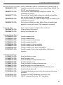
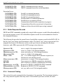
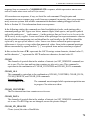
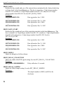
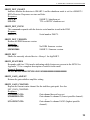
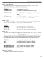
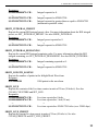
8. FIRMWARE COMMANDS AND RESPONSES . . . . . . . . . . . . . . . . . . . . . . . . . . . . . . . . . 71
8.1. CONNECTIONS-32 . . . . . . . . . . . . . . . . . . . . . . . . . . . . . . . . . . . . . . . . . . . . . . . . . . . . . . 71
8.1.1. Command Records . . . . . . . . . . . . . . . . . . . . . . . . . . . . . . . . . . . . . . . . . . . . . . . 71
8.1.2. Percent Response Records . . . . . . . . . . . . . . . . . . . . . . . . . . . . . . . . . . . . . . . . . 72
8.1.3. Dollar Response Records . . . . . . . . . . . . . . . . . . . . . . . . . . . . . . . . . . . . . . . . . . 74
8.1.4. Command Catalog . . . . . . . . . . . . . . . . . . . . . . . . . . . . . . . . . . . . . . . . . . . . . . . 74
8.2. Direct Communication . . . . . . . . . . . . . . . . . . . . . . . . . . . . . . . . . . . . . . . . . . . . . . . . . 112
INDEX . . . . . . . . . . . . . . . . . . . . . . . . . . . . . . . . . . . . . . . . . . . . . . . . . . . . . . . . . . . . . . . . . . . . 113
vii
viii
1. INTRODUCTION
The ORTEC digiDART® is a low-power, hand-held HPGe-grade MCA based on low-power
digital signal processing (DSP) technology. It is ideal for:
!
!
!
!
!
In-situ gamma spectroscopy
Fissile material assay
Chemical weapons assay — PINS
Comprehensive nuclear test ban treaty activities (inspection systems)
Non-fissile waste assay
Lighter in weight and more rugged than any previous portable MCA, the digiDART gives you a
full suite of features for in-field data acquisition. The display shows the spectra you are
collecting in the field in live time, without using a laptop. With the keypad you can view or
change any of the data-acquisition settings and internal parameters whenever you need to,
without a PC.
The digiDART can perform real-time identifications and activity calculations for up to 9 userdefined nuclides at a time. Everything is user-controlled: the library for analysis, displayed peak
labels, unit labels, calibration parameters, regions of interest (ROIs), and data acquisition
settings. These can all be downloaded from MAESTRO-32 to the digiDART or you can set them
up from the instrument’s keypad. You can also adjust parameters such as gain and pole zero
whenever needed, without a PC.
Spectra can be saved and later uploaded to a PC and reanalyzed in more detail using a more
sophisticated analysis package such as our GammaVision®-32 MCA Emulation and Analysis
Software (A66-B32).
The digiDART also offers these features:
! Small enough to mount on a detector Dewar or attach easily to an ORTEC M-1 tripod.
! Rugged ABS plastic case with a shock-resistant elastomer covering.
! The cable between the MCA and detector does not carry high voltage, so the digiDART is
protected from electrical damage.
! Connects to the host PC via the USB port.
! Long battery life — up to 12 hours on a single battery.
! Highly stabile peak shape and peak position with temperature and count rate.
! Optimize detector performance for a given application from the digiDART or from the PC
using the InSight™ Virtual Oscilloscope.
! ORTEC’s easy automatic pole-zero adjustment.1
! Administrator and user passwords entered from the digiDART keypad only (not PC
1
Patent number 5,872,363.
1
digiDART® Portable HPGe MCA User’s Manual
software). provides added security for your data.
! Monitor the contents and capacity of the stored-spectrum memory.
! Highly accurate Gedcke-Hale extended live-time correction method.2
! In-the-field accessories for ease of use in all conditions.
The digiDART is the first MCB to support ORTEC’s SMART-1® HPGe detector technology,
which monitors and records the detector’s “state of health” (SOH), including detector
temperature. It supports HPGe, NaI, CZT, and other detector types. The digiDART can also use
our DIM-POSNAI and DIM-296 detector interface modules (DIMs) to supply detector bias.
Attached to a PC or laptop (running any version of Microsoft® Windows® listed in Section ?),
the digiDART operates just like any other ORTEC CONNECTIONS-32 MCB and is compatible
with all CONNECTIONS-32 products and our CONNECTIONS-32 Programmer’s Toolkit (A11-B32).
It is backward compatible with existing CONNECTIONS-32 custom applications at the general
operation/control level. And because the digiDART is part of our CONNECTIONS-32 architecture,
its operations can be controlled remotely over a network, with the authentication performed at
the data source, making the digiDART ideal for unattended monitoring applications.
1.1. How the digiDART Collects and Stores Spectra
The live or current spectrum and all the associated information are stored in high-speed
spectrum memory. The spectrum can then be stored in the stored-spectrum memory. Both the
live spectrum and the stored spectra are retained when power is turned off and when the battery
is removed.
1.1.1. Live Spectrum
The currently acquiring or most recently acquired spectrum is stored here. This also holds the
presets, ROIs, calibration, and the SOH status. This spectrum is lost when CLEAR is pressed or
when a stored-spectrum is recalled or read by the PC.
1.1.2. Stored-Spectrum Memory
Stored-spectrum memory is the storage place for spectral data acquired in the field. At the end of
a data acquisition, simply press the Store button to copy the spectrum and all the information
associated with this acquisition, including the presets, ROIs, calibration, and SOH bit from the
live memory to stored-spectrum memory. This entire set of data can be downloaded to the host
PC using a program such as MAESTRO. The file can then be saved as an .SPC file.
2
Ron Jenkins, R. W. Gould, and Dale Gedcke, Quantitative X-Ray Spectrometry (New York: Marcel Dekker,
Inc.), 1981, pp. 266–267.
2
1. INTRODUCTION
The stored spectra are retained until you delete them, even when the digiDART is powered off
and has been disconnected from all external and battery power.
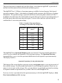
The digiDART has 1.5 Mbytes of spectrum memory available for stored-spectra. Each stored
spectrum consumes 4 bytes × the number of channels in the spectrum, plus 400 bytes of settings
information. The spectrum storage required for different conversion gains is shown in Table 1.
In addition, the table shows the total number of spectra that can be stored in spectrum memory if
all of the spectra have the same conversion gain. You can collect and store spectra with any
combination of conversion gain settings.
Table 1. Capacity of Spectrum Memory
According to Conversion Gain Setting Used.
Conversion
Gain
Memory Required
(bytes)
Total
Spectr
a
32k
131472
12
16k
65936
24
8k
33168
48
4k
16784
96
2k
8592
188
1k
4496
360
512
2448
662
The digiDART has a Spectrum Memory menu (see Section 2.2 for more details) that allows
you to view the contents and remainder of the spectrum memory. The Spectrum Directory
command allows you to view the spectrum identification for the spectra in spectrum memory.
The display format is :
sequence# spectrum_id start_date start_time
The bottom of the screen displays a message saying x# of y# bytes used so you can keep track of
the available storage. Use the up and down arrows to scroll through the spectra (if there are too
many to view at once on the screen). Also, you can advance to a particular spectrum by entering
its sequence number or spectrum ID so you don’t have to scroll through the list.
If you try to store a spectrum when the spectrum memory is full, the digiDART displays a
Error: Spectrum Memory is Full message.
Write
3
digiDART® Portable HPGe MCA User’s Manual
1.2. Host PC and Software Requirements
The digiDART can be operated with any suitable version of ORTEC software, including
MAESTRO-32 MCA Emulation Software version 5.2 or higher. The digiDART is supported on
any Microsoft® Windows® PC that supports the USB port. The current release of MAESTRO-32
runs under Windows 2000 Professional SP4, XP Professional SP2 or higher, and Vista Ultimate.
4
2. THE DIGIDART
2.1. Display and Keypad
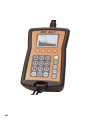
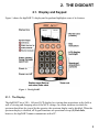
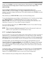
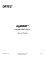
Figure 1 shows the digiDART’s display and keypad and highlights some of its features.
Figure 1. The digiDART.
2.1.1. The Display
The digiDART has a 240 × 160-pixel LCD display for viewing data acquisitions in the field as
well as viewing and changing most of the MCA settings. In certain situations in which the
spectrum should not be viewed by the operator, the spectrum display can be disabled. When the
spectrum display is disabled, all keypad functions are operational except (5) Peak Info,
however, the digiDART cannot communicate with a PC.
5
digiDART® Portable HPGe MCA User’s Manual
The left and right arrow buttons allow you to move the vertical Marker Line by one channel or
one pixel. The (0) through (6) number keys move the marker quickly through the spectrum.
The marker channel is used in the following:
! The status line shows details of the marker channel on the display.
! Peak Info is displayed for the peak ROI containing the marker.
! The spectrum Zoom in and Zoom out functions expand or contract the spectrum’s horizontal
axis around the marker position.
The Status Line at the top of the display can show any two of the following parameters: cursor
location (energy), cursor location (channel), live time, real time, live time remaining, real time
remaining, battery time remaining, count rate, count rate in the current ROI (selected with the
marker), and counts in the ROI. Selection of these parameters can only be done from the keypad.
The ROI Indicator line at the bottom of the display shows which channels in the spectrum have
the ROI bit set. The ROIs can be set using the digiDART keypad and menus (Section 4.1.12) or
from a program such as MAESTRO.
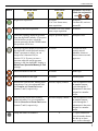
2.1.2. Keypad
The keypad allows you to use the digiDART without a host PC. The following table tells how to
use the buttons in spectrum mode, menu mode, and parameter/text entry mode. The
parameter/text entry mode allows you to enter alphanumeric ROI labels and ROI units for the
Nuclide Report, and spectrum sample IDs. All keys are disabled when the digiDART is
connected to a PC.
Button
Spectrum Mode
Menu Mode
Parameter/Text Entry
Mode (in conjunction
with
and
)
Returns you to the previous
menu. From the Main
Menu, returns you to
spectrum mode.
Completes the entry of a
parameter value.
Turns the digiDART on and off. See Section 3.5.
Switches to the Main Menu.
Turns on the display backlight. The backlight remains on for 10 seconds after the last button press
then turns off.
6
2. THE DIGIDART
Button
Spectrum Mode
Menu Mode
Parameter/Text Entry
Mode (in conjunction
with
and
)
Begins data acquisition.
No action.
If in View Status menu,
starts acquisition.
No action.
If in Enter ID, retrieves
current ID.
Manually ends data acquisition.
No action. If in View Status
menu, stops acquisition.
No action.
Erases the currently displayed spectrum
from the digiDART memory. If you press
CLEAR before you have saved the
current spectrum with the STORE button,
the spectrum will be lost.
Jump to spectrum display.
Backspace/erase.
Saves the currently displayed spectrum in
the digiDART stored-spectrum memory.
When a spectrum is stored, you can
assign it an 8 character ID (see
Section 2.2.2). If you try to store a
spectrum when the stored spectrum
memory is full, the digiDART displays a
No action.
Switches the most
recently entered
alphabetic character
between lowercase and
uppercase.
Moves the marker to the left.
No action.
Minus sign.
Moves the marker to the right.
No action.
Decimal point.
Increase the vertical scale, making peaks
look shorter. Use it in conjunction with
the Zoom In and Zoom Out buttons
(buttons 7 and 9, respectively).
Increases display contrast.
Used in conjunction with
the number buttons;
cycles through the 3
alphanumeric characters
assigned to a number
button.
Decreases the vertical scale, making
peaks look taller. Use it in conjunction
with the Zoom In and Zoom Out buttons
(buttons 7 and 9, respectively).
Decreases display contrast.
Used in conjunction with
the number buttons;
cycles through the 3
alphanumeric characters
assigned to a number
button.
0
0, /, space, underscore
Press the number button
then the up or down
arrow to move through
Write Error: Spectrum Memory is Full
message.
Jumps the marker to channel 0.
7
digiDART® Portable HPGe MCA User’s Manual
Button
Spectrum Mode
Menu Mode
Parameter/Text Entry
Mode (in conjunction
with
and
)
the letter/symbol
choices. Press STORE to
switch between
lowercase and uppercase
letters.
Jumps the marker to the channel at 1/6 of
the display.
1
1, A, B, C
Jumps the marker to the channel at 1/3 of
the display.
2
2, D, E, F
Jumps the marker to the channel at 1/2 of
the display.
3
3, G, H, I
Jumps the marker to the channel at 2/3 of
the display.
4
4, J, K, L
Jumps the marker to the channel at 5/6 of
the display.
5
5, M, N, O
Jumps the marker to the right-most
channel on the display.
6
6, P, Q, R
Zoom In; Each button press reduces the
number of channels displayed by half, to
a minimum of 240 channels. The zoom-in
view is centered on the marker location.
7
7, S, T, U
This is used as a “shift” or “function” key
when used in combination with other
buttons. Press and hold the 8 button, press
the second button in the combination,
then release both.
8
8, V, W, X
! <8+Left-arrow> moves the marker to
the lowest-channel ROI.
! <8+Right-arrow> moves the marker
to the next ROI to the right.
! <8+Up-arrow> Sets the display mode
to linear autoscale.
! <8+1> Sets the display mode to
logarithmic.
! <8+3> sets the first point of a new
ROI at the current marker location.
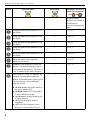
8
2. THE DIGIDART
Button
Spectrum Mode
Menu Mode
Parameter/Text Entry
Mode (in conjunction
with
and
)
! <8+6> sets the endpoint for the new
ROI and fills in the ROI. This endpoint
can be at a lower channel number or
energy than the start point, but you
must start marking with <8+3> and
end with <8+6>.
! <8+4> removes the ROI if the marker
is in an ROI region.
! <8+7> zooms the horizontal axis to
maximum expansion (240 channels).
! <8+9> zooms to minimum expansion
(maximum number of channels).
! <8+CLEAR> jump back to menu
Zoom Out; doubles the number of
channels displayed, the marker is centered
in the display.
9
9, Y, Z, @
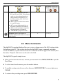
2.2. Menu Commands
The digiDART keypad and display allow you to view or change most of the MCA settings in the
field without a host PC. This section describes the digiDART menus, commands, and status
screens. In addition, a quick reference menu tree is included on the last page of the manual (after
the index). Chapter 4 tells how to use the unit in the field.
The digiDART keypad is simple to use:
! When you first turn the unit on, it starts in spectrum mode. Press MENU/ENTER to open the
Main Menu.
! To select items from the menus, press the number buttons.
! To modify a setting, enter the new value, then press MENU/ENTER. To erase a digit, press
CLEAR.
! To return to the preceding menu, press MENU/ENTER.
9
digiDART® Portable HPGe MCA User’s Manual
! There are two ways to return to spectrum mode from any menu: (1) press MENU/ENTER
until the spectrum is displayed; or (2) press CLEAR. If you press CLEAR to jump from a
menu to spectrum mode, you can jump back to that menu by pressing <8+CLEAR>.
! On any entry, if you just press MENU/ENTER without pressing any other keys, the current
value will be used; that is, no change will be made. Therefore, if you enter a dialog by
mistake, you can just press MENU/ENTER to go back without changing anything.
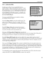
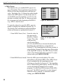
The Main Menu for the USB digiDART is shown in
Fig. 2. For the digiDART-R’s main menu, see the
digiDART-R user’s manual supplement.
1
2
3
4
5
6
7
8
9
-
View Status
Enter ID
Nuclide ROIs
Status Line
Peak Info
Adjust Controls
General Settings
Spectrum Memory
Nuclide Report
Figure 2. The Main Menu.
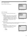
2.2.1. (1) View Status
The status screen (Fig. 3) displays all of the major
MCA settings at one time. Press MENU/ENTER to
return to the Main Menu.
Live Time (sec)
Real Time (sec)
% Dead Time
Battery Time Remains
Bias Voltage (Volts)
Fine Gain
Coarse Gain
RiseTime
FlatTop
BLR Setting
Figure 3. View Status.
2.2.2. (2) Enter ID
Allows you to enter an 8-character alphanumeric
identifier to describe the sample, as shown in Fig. 4.
Enter ID:
> TEST 001
Current ID is SEALAKE1
Figure 4. Enter Spectrum ID.
10
2. THE DIGIDART
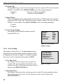
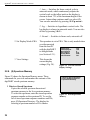
2.2.3. (3) Nuclide ROIs
Use this screen (Fig. 5) to set up the ROIs for the
Nuclide Report, which is described in Section 6.1. Each
ROI is labeled as ACTIVE (the ROI will be displayed on
the Nuclide Report screen) or DISABLED (the ROI will
not be displayed on the report screen). To view the realtime Nuclide Report for the currently active ROIs, press
(0) View Nuclide Report.
1 Nuclide ROI 0 (ACTIVE)
2 Nuclide ROI 1 (ACTIVE)
3 Nuclide ROI 2 (DISABLED)
4 Nuclide ROI 3 (DISABLED)
5 Nuclide ROI 4 (ACTIVE)
6 Nuclide ROI 5 (ACTIVE)
7 Nuclide ROI 6 (DISABLED)
8 Nuclide ROI 7 (DISABLED)
9 Nuclide ROI 8 (DISABLED)
0 View Nuclide Report
Figure 5. Nuclide Report ROIs.
To set up a nuclide ROI, press its number to display
the submenu shown in Fig. 6.
Press (1) Change Label to enter the nuclide name. The
name can be 6 characters long (for example, AM-241).
See Section 2.1.2. for instructions on entering the various
characters.
Press (2) Change Units and enter the desired unit of
measure (text, up to 6 characters). The same units label
is used for all entries and is only entered once.
1 - Change Label
2 - Change Units
3 - Change Start Channel
4 - Change ROI Length
5 - Change Constant
6 - Clear ROI
7 - Show ROI Setup
Figure 6. Set Up the ROIs.
Next press (3) Change Start Channel and enter the start
channel for the region. The start channel should below (on the low-energy side of) the peak in
the background. The first 3 channels are used for the low-energy background.
Press (4) Change ROI Length and enter the width of the region, which must be at least 7
channels. The width should stop above (on the high-energy side of) the peak in the background
so that the region is approximately centered on the peak channel. The last 3 channels are used
for the high-energy background.
Next, press (5) Change Constant. The constant is multiplied times the net peak count rate to
give the value shown on the report. To report activities, you need to know the branching ratio
(yield) for this gamma ray for this nuclide and the efficiency. The branching ratio can be found
in any gamma-ray library (e.g., NuclideNavigator® III). The efficiency can be calculated by a
program such as ScintiVision or determined by other methods.
To confirm that you have entered the desired values and labels, press (7) to show the current
setup for this ROI. Press MENU/ENTER to return to the setup list.
11
digiDART® Portable HPGe MCA User’s Manual
When setup is complete, press MENU/ENTER to return to the Nuclide Report list of ROIs. The
ROIs you have set up will now be marked ACTIVE.
To enter another region, press the number and repeat entry as described above.
To remove an ROI from the report, press the corresponding Nuclide ROI number to open the
setup list, then press (6) Clear ROI. This will completely remove all the setup information for
this one ROI, which will now be marked DISABLED on the Nuclide ROIs screen.
The Nuclide Report will display the active ROIs in the order entered on this setup screen. Note
that these ROIs are separate from the spectrum ROIs discussed in Section 4.1.12, and are not
displayed or marked in any way on the spectrum screen.
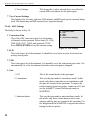
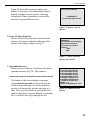
2.2.4. (4) Status Line
The Status Line at the top of the spectrum display can
show any two of the parameters shown in Fig. 7.
1*1 - Cursor Location (Energy)
2 - Cursor Location (Channel)
3 - Live Time
4 - Real Time
5 - Live Time Remaining
6 - Real Time Remaining
7 - Battery Time Remaining
8 - Count Rate
9 - Count Rate in ROI
2*0 - Counts
The numbers are select/deselect toggles (i.e., press a
number once to select an item, and press again to deselect it). When you mark the first status item, a 1*
appears beside your first selection. This parameter is
displayed at the top left of the spectrum. The second
Figure 7. Set Up the Status Line.
status item is marked with 2* and is displayed at the top
right. The order in which you select items allows you to
determine which parameter is shown on the left and right sides of the display.
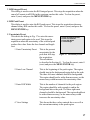
2.2.5. (5) Peak Info
When you place the marker in a defined ROI and issue
this command, it reports the centroid, FWHM, and net
and gross counts for the region (Fig. 8). Access is denied
when the spectrum display is locked. If the marker is not
in an ROI, all values are shown as N/A.
Peak Centroid
FWHM
Net Counts
Gross Counts
ROI Start Channel
ROI End Channel
Figure 8. Peak Info.
12
1332.5
2.03
52971
83497
4320
4352
2. THE DIGIDART
2.2.6. (6) Adjust Controls
The list of controls is shown in Fig. 9.
1 - HV Settings
2 - Amplifier Settings
3 - Presets Settings
4 - ADC Settings
5 - Stabilizer Settings
Figure 9. Adjust Controls.
2.2.6.1. HV Settings
This dialog (Fig. 10) includes the following functions:
1 Enable HV
Turns on the high voltage. If no detector (SMART-1
or DIM) is attached or if HV is in shutdown status,
the Error: Cannot Enable HV message is displayed.
If Disable HV is displayed, the HV is on and pressing
(1) will turn it off. When the voltage is enabled/
disabled, a message is displayed until you press
MENU/ENTER.
1 - Enable HV
2 - Set Bias Voltage
3 - Set Shutdown
4 - View Current HV
5 - View HV SOH
Figure 10. HV Settings.
2 Set Bias Voltage
This sets the HV to the desired voltage. The polarity is determined by the SMART-1 or
DIM. The recommended voltage is shown for the SMART-1.
3 Set Shutdown
When connecting to a SMART-1 HPGe Detector,
select (3). For using “non-SMART-1” detectors,
choose (1) TTL or (2) ORTEC (Fig. 11).
1 - TTL
2 - ORTEC
3 - SMART
1 TTL
2 ORTEC
3 SMART
Figure 11. Set Shutdown.
13
digiDART® Portable HPGe MCA User’s Manual
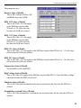
4 View Current HV
This displays the current HV parameters as shown
in Fig. 12. The Type can be GE-POS, GE-NEG, or
NaI.
HV Status
HV Target Bias
HV Actual Bias
HV Shutdown
Type
Overloaded Status
HV Serial #
SMART-1 Detector
Recommend HV
Live Det. Temp
OFF
0
0
ORTEC
GE-POS
NO
0
NO
92
Figure 12. View Current HV
Settings.
5 View HV SOH
This displays the HV and other state-of-health
flags as shown in Fig. 13.
+24V
+12V
-12V
-24V
Temp
HV Volt
Shutdown
Overload
Security
Power
OK
OK
OK
OK
OK
OK
OK
OK
ERR
OK
+0.00
+0.00
+0.00
+0.00
+0.00
Figure 13. Monitor the SOH
Flags.
2.2.6.2. Amplifier Settings
These settings (Fig. 14) should be performed in this order:
9, 8, 6, 3, 4, 1, 2, 7. The Device Busy message means the
unit is collecting data; to continue changing the amplifier
settings, return to spectrum mode and press STOP.
1 Coarse Gain
This sets the amplifier coarse gain to ×1, ×2, ×4, ×8,
×16 or ×32.
1 - Coarse Gain
2 - Fine Gain
3 - Rise Time
4 - Flattop
5 - Pole Zero
6 - Baseline Restore
7 - Optimize
8 - Preamp Type
9 - Input Polarity
0 - View Current Settings
Figure 14. Amplifier Settings.
2 Fine Gain
This sets the amplifier fine gain to any value between 0.45 and 1.00.
3 Rise Time
This sets the rise time to values between 0.8 and 23.0. Values less than 0.8 are
automatically adjusted up to 0.8. Values greater than 23.0 are adjusted down to 23.0.
14
2. THE DIGIDART
4 Flattop
This sets the filter flattop width to values between 0.3 and 2.4. Values less than 0.3 are
automatically adjusted up to 0.3. Values greater than 2.4 are adjusted down to 2.4.
5 Pole Zero
This shows the PZ dialog, where you select either manual or automatic PZ. Note that if
you use the Optimize function, it automatically PZs the digiDART
1 Enter Manual PZ Setting
This allows you to enter the PZ value to any number
between 1 and 4095.
2 Perform Auto-PZ
This performs the auto pole zero. The unit must be
collecting data with a dead time less than 10% for best
results. The PZ process does not start until you reply
that the unit is ready to start by pressing 1 on the next
dialog. You can press MENU/ENTER to return to the
previous menu at this time. During the PZ process, the
current PZ value is displayed. To abort the PZ process,
press the MENU/ENTER key.
6 Baseline Restore
This opens a dialog listing three Baseline Restore settings. Select the desired setting by
pressing 1, 2, or 3. After you select a setting, the display returns to the Amplifier Settings
menu.
1 Auto
This sets the baseline restorer time constant to the
automatic mode. This is the normal setting.
2 Fast
This sets the baseline restorer to operate in the fast
restore mode for high-count-rate situations.
3 Slow
This sets the baseline restorer to operate in the slow
restore mode for low-count-rate situations.
7 Optimize
This performs the optimize and pole-zero process. For best results, the digiDART must
be collecting data with a dead time less than 10%. Optimization does not start until you
press 1 on the next dialog to indicate that the unit is ready to start. If you wish to return
to the previous menu at this time, press MENU/ ENTER. During optimization, a row of
dots is displayed to show progress. To abort the Optimize process, press
MENU/ENTER.
15
digiDART® Portable HPGe MCA User’s Manual
8 Preamp Type
The preamplifier type must be set for the type of detector connected. This is true for both
SMART-1 and DIMs. Press MENU/ENTER to leave the setting unchanged.
1 Resistive
2 TRP
Resistive-feedback preamplifier
Transistor-reset preamplifier
9 Input Polarity
This sets the polarity for the input signal from the detector. GEM detectors have positive
output and GMX, LEPS, and LOAX detectors have negative output. This is true for both
SMART-1 and for DIMs. Press MENU/ ENTER to leave the setting unchanged.
1 Positive
2 Negative
0 View Current Settings
This displays all the amplifier settings currently
being used (Fig. 15).
Coarse Gain
Fine Gain
Rise Time
Flat Top
Pole Zero
Baseline Restore
Preamp Type
Input Polarity
2
0.500
12.000
0.8000
2220
SLOW
RES
POS
Figure 15. View Current
Amplifier Settings.
2.2.6.3. Preset Settings
This dialog is shown in Fig. 16. The Device Busy message
means the unit is collecting data and this parameter cannot
be changed until the unit is stopped. To continue changing
the presets, return to spectrum mode and press STOP.
1 Live Time Preset
This dialog is used to enter the live time preset in
seconds. This stops acquisition when the live time
reaches this value. To clear the preset, enter 0 (zero)
and press the MENU/ENTER key.
1 - Live Time Preset
2 - Real Time Preset
3 - ROI Integral Preset
4 - ROI Peak Preset
5 - Uncertainty Preset
6 - MDA Presets
7 - View Current Settings
Figure 16. Presets.
2 Real Time Preset
This dialog is used to enter the real time preset in seconds. This stops acquisition when
the real time reaches this value. To clear the preset, enter 0 (zero) and press the
MENU/ENTER key.
16
2. THE DIGIDART
3 ROI Integral Preset
This dialog is used to enter the ROI integral preset. This stops the acquisition when the
sum of all counts in all ROIs in the spectrum reaches this value. To clear the preset,
enter 0 (zero) and press the MENU/ENTER key.
4 ROI Peak Preset
This dialog is used to enter the ROI peak preset. This stops the acquisition when any
channel in any ROI reaches this value. To clear the preset, enter 0 (zero) and press the
MENU/ENTER key.
5 Uncertainty Preset
This shows the dialog in Fig. 17 to enter the uncertainty preset and region to be used. This stops the
acquisition when the uncertainty of the selected peak
reaches this value. Enter the low channel and length
first.
1 - Enter Uncertainty Preset
2 - Enter Low Channel
3 - Enter ROI Width
4 - View Settings
1 Enter Uncertainty Preset
This is the percent
uncertainty for the
Figure 17. Uncertainty Preset.
peak that will stop
the acquisition.
The calculation
is described in Section 6.1. To clear the preset, enter 0
(zero) and press the MENU/ENTER key.
2 Enter Low Channel
This is the beginning of the peak region. The region
should start in the background region below the peak.
The three left-most channels should be background.
The region should not be wider than necessary, as the
unnecessary width increases the uncertainty value.
3 Enter ROI Width
This is the number of channels for the peak region.
The region should be wide enough to end in the
background above the peak. The three right most
channels should be background. The region should not
be wider than necessary, as the unnecessary width
increases the uncertainty value.
4 View Settings
This shows the three values entered above as well as
the current uncertainty in the peak region.
17
digiDART® Portable HPGe MCA User’s Manual
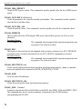
6 MDA Presets
This function lets you establish MDA presets for
up to 20 nuclides. Data acquisition stops when the
MDAs of all of the selected peaks reach their set
value. The dialog (Fig. 18) shows the enable/disable
status of the MDA presets. Use the down arrow to
see the MDA preset for nuclides 11 to 20. Use the
up arrow to return to the first 10. The presets must
be set in numerical order beginning with MDA 0
(e.g., MDA 1 must be next).
To enter the values for a specific MDA, press its
number to display the submenu shown in Fig. 19.
The details of the calculations and the definitions
of the coefficients are explained in Section 6.2.
1 - MDA 0
2 - MDA 1
3 - MDA 2
4 - MDA 3
5 - MDA 4
6 - MDA 5
7 - MDA 6
8 - MDA 7
9 - MDA 8
0 - MDA 9
(ACTIVE)
(ACTIVE)
(ACTIVE)
(ACTIVE)
(DISABLED)
(DISABLED)
(DISABLED)
(DISABLED)
(DISABLED)
(DISABLED)
Figure 18. MDA Presets.
1 - Enter MDA Preset (User)
2 - Enter MDA Preset (Actual)
3 - Enter MDA Coefficient
4 - Enter Low Channel
5 - Enter ROI Length
6 - Enter Efficiency Yield
7 - Enter Nuclide Name
8 - Clear MDA
9 - View Settings
1 Enter MDA Preset (User) Enter the value for
the preset as displayed by GammaFigure 19. Set Up an MDA
Vision. This value
Preset.
is the preset in
activity units (Bq or
µCi). It is the MDA Preset (Actual) divided by the
branching ratio and efficiency as described in
Section 6.2. The branching ratio-efficiency product is
entered below. GammaVision also stores this product
in the digiDART memory. The MDA Preset (Actual)
value is also changed when this is entered. To retain
current value, press MENU/ENTER.
2 Enter MDA Preset (Actual) Enter the MDA preset in this dialog. The value
entered here is the desired MDA value (MDA Preset
[User]) multiplied by the branching ratio and
efficiency as described in Section 6.2. The branching
ratio is found in the gamma library, and the efficiency
can be calculated in GammaVision or similar
programs. Use (5) Clear MDA to turn off this MDA
preset off. The MDA Preset (User) is also changed
when this value is entered. To retain the current
setting, press MENU/ENTER.
18
2. THE DIGIDART
3 Enter MDA Coefficient
These are the MDA coefficients used in the MDA
calculation (see Section 6.2). These coefficients
depend on the MDA formula used. You can enter any
coefficients here, but to have the values correspond to
the MDA value calculated in the software such as
GammaVision, use the values shown in the
GammaVision dialog for MDA preset.
The three coefficients are entered as decimal numbers.
These coefficients are used for all 20 MDA
calculations. Changing them for one MDA changes
them for all MDAs. It is only necessary to enter them
once.
4 Enter Low Channel
This is the beginning of the peak region. The region
should start in the background region below the peak.
The three left-most channels should be background.
The region should not be wider than necessary, as the
unnecessary width increases the background and the
MDA value.
5 Enter ROI Length
This is the number of channels for the peak region.
The region should be wide enough to end in the
background above the peak. The three right-most
channels should be background. The region should not
be wider than necessary, as the unnecessary width
increases the background and the MDA value.
6 Enter Efficiency Yield
Enter the product of the detector efficiency and the
gamma-ray yield or branching ratio. This value is
entered by GammaVision when you use it to setup the
Preset. To retain the current value, press
MENU/ENTER. MDA Preset (Actual) = Efficiency
Yield product × MDA Preset (User).
7 Enter Nuclide Name
Enter the nuclide name to be displayed in the MDA
table and in the software display. This is loaded by the
software when the preset is set to retain the current
name, press MENU/ENTER.
8 Clear MDA
This disables the current MDA and sets all of the
settings to 0, except the coefficients.
19
digiDART® Portable HPGe MCA User’s Manual
9 View Settings
This shows the 6 values entered above as well as the
current MDA calculation for the peak region.
7 View Current Settings
This displays the live time, real time, ROI integral, and ROI peak presets currently being
used. The uncertainty and MDA presets have separate displays.
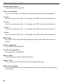
2.2.6.4. ADC Settings
The dialog is shown in Fig. 20.
1 Conversion Gain
This is the ADC conversion gain. It is the number
of channels in the spectrum. Select from 512, 1024,
2048, 4096, 8192, 16384, and (optional) 32768.
Press MENU/ENTER to keep the current setting.
1 - Conversion Gain
2 - LLD
3 - ULD
4 - Gate
5 - View Current Settings
Figure 20. ADC Settings.
2 LLD
This is the lower-level discriminator. It should be set to reject any low-level noise but
not any useful peaks.
3 ULD
This is the upper-level discriminator. It is normally set to the conversion gain value. It is
automatically set to the last channel when the conversion gain is changed.
4 Gate
20
1 Off
This is the normal mode of the gate input.
2 Coincidence
This sets the gate mode to coincidence mode. In this
mode, only those counts that are in coincidence with
the gate are counted in the spectrum. To inspect the
relative timing for the two pulses, connect to a PC and
use the InSight™ Virtual Oscilloscope mode in
MAESTRO.
3 Anticoincidence
This sets the gate mode to anticoincidence mode. In
this mode, only those counts that are not in coincidence with the gate are counted in the spectrum. Use
the InSight mode in MAESTRO to inspect the relative
timing for the two pulses.
2. THE DIGIDART
5 View Current Settings
This displays the ADC settings currently being used.
2.2.6.5. Stabilizer Settings
The dialog is shown in Fig. 21. Gain and zero stabilization
are discussed in detail in Sections 6.3 and 6.4, respectively.
1 Enable Gain Stabilization
This will enable the gain stabilizer to operate. The
stabilizer must be set up before it can be enabled.
An error message is displayed if the stabilization
cannot be enabled. A confirmation message is
shown if the stabilizer is enabled. Press MENU/
ENTER to continue.
1 - Enable Gain Stabilization
2 - Gain Stab Center Channel
3 - Gain Stab Width
4 - Initialize Gain Stab
5 - Enable Zero Stabilization
6 - Zero Stab Center Channel
7 - Zero Stab Width
8 - Initialize Zero Stab
9 - Enable NaI
0 - View Current Settings
Figure 21. Stabilizer Settings.
2 Gain Stab Center Channel
This is the center channel of the region used for the stabilization. The peak will be
centered in this region by the stabilizer operation. The peak should be in the upper half
of the spectrum and isolated from other peaks.
3 Gain Stab Width
This is the width (in channels) of the peak region to be used. It should be slightly wider
than the peak, but not overly wide.
4 Initialize Gain Stabilization
Resets the gain peak stabilization adjustment to unity (no adjustment).
5 Enable Zero Stabilization
This enables the zero stabilizer to operate. The stabilizer must be set up before it can be
enabled. A confirmation message is shown when the stabilizer is enabled; an error
message is displayed if stabilization cannot be enabled. Press MENU/ENTER to
continue.
6 Zero Stab Center Channel
This is the center channel of the region used for the stabilization. The peak in this region
will be centered by the stabilizer operation. The peak should be in the lower quarter of
the spectrum.
7 Zero Stab Width
This is the width (in channels) of the peak region to be used. It should be slightly wider
than the peak, but not overly wide.
21
digiDART® Portable HPGe MCA User’s Manual
8 Initialize Zero Stab
Resets the zero peak stabilization adjustment to unity (no adjustment).
9 Enable NaI
This is an enable/disable toggle. Enable switches the bias supply to the NaI (highcurrent, low-voltage) mode. Disable switches to the Ge (low-current, high-voltage)
mode. The HV is turned off when this command is sent.
0 View Current Settings
This displays the stabilizer settings currently being used.
2.2.7. (7) General Settings
These commands (Fig. 22) control instrument access,
calibration, and the LCD display.
1 Change User Password
Use this to set a numeric password to prevent
unauthorized use of the instrument. The password
is limited to 9 digits. When the user password has
been set, the digiDART prompts for it on powerup. To clear the password, enter 0 (zero) for the
password, then press MENU/ENTER.
1 - Change User Password
2 - Change Admin Password
3 - Enter Password
4 - Lock Spectral Display
5 - Auto-Contrast
6 - Calibrate
7 - Display
Figure 22. General Settings.
2 Change Admin Password
Use this to set a numeric administrator password that prevents other users from changing
the current digiDART settings. The password is limited to 9 digits. When the
administrator password has been set, users (as distinguished from administrators) can
view the current settings and the spectrum, unless the display is locked. They can also
START and STOP data acquisition. However, if users try to change settings, an
“Access denied” message will be displayed. Use (3) Enter Password to enter the
administrator password and gain full access.
If the administrator password is not set, all users have full access to all functions. To
clear the password, enter 0 (zero) for the password, then MENU/ENTER.
If the user and administrator passwords are identical, the digiDART will grant
administrator (full) access when the user password is entered. See Section 4.1.15.
NOTE There is no master administrator password. If you lose this password, contact
your ORTEC service representative or our Global Service Center.
22
2. THE DIGIDART
3 Enter Password
Allows you to enter the administrator password so you can switch to administrator mode
and then change the digiDART settings. See Section 4.1.15.
To exit administrator mode, turn the power off and on, then enter user password if
needed.
4 Lock Spectral Display
This locks (turns off) or unlocks (displays) the spectrum display and Peak Info
command. The unit must be in administrator mode to lock or unlock the display. Select
(4) to switch from lock to unlock or unlock to lock. The display is not turned off until
you leave administrator mode by turning the digiDART off then back on.
NOTE
When the display is locked the unit will not respond to PC-based software
commands.
5 Auto-Contrast
Automatically adjusts display contrast as ambient temperature changes. Note that you
can also adjust the contrast in menu mode by the up/down arrow buttons.
1 Enable Auto-Contrast
2 Disable Auto-Contrast
6 Calibrate
Allows you to enter slope and intercept (linear) calibration coefficients from the keypad.
This replaces the previous calibration, including calibrations from the host PC. See
Section 4.1.10 for more details. This calibration will be read by software when the
digiDART is connected to the PC.
1 Enter Slope
This can be any positive decimal number.
2 Enter Intercept
This can be any positive or negative decimal number.
3 View Current Calibration
7 Display
Figure 23 shows the Display menu.
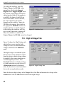
1 Adjust Scale
Selects between
linear and log and
autoscale on or
autoscale off.
Autoscale Off
applies only to
linear displays.
1 - Adjust Scale
2 - Set Display Mode=PHA
3 - View Settings
Figure 23. Adjust Display
Settings.
23
digiDART® Portable HPGe MCA User’s Manual
1 Auto — Switches the linear vertical scale to
autoscale mode, which continuously adjusts the
vertical scale so the tallest peak on the display is
shown at about 75% of the maximum height of the
screen. Autoscaling continues until you select (3).
You can also autoscale by pressing <8+Up-arrow>.
2 Log — Switches to logarithmic vertical scale. The
log display is always in autoscale mode. You can also
do this by pressing <8+1>.
3 Normal — Switches to linear scale, autoscale off.
2 Set Display Mode=PHA
The operation is set to PHA. This is only needed when
you disconnected
from the host PC
Scale Factor
Log
with the digiDART
Peak Displayed
120
Start Channel
0
in InSight mode
End Channel
272
Display Mode
PHA
(see Section 4.3.1).
Auto-Contrast
3 View Settings
This shows the
current display
settings (Fig. 24).
ON
Figure 24. View the Current
Display Settings.
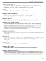
2.2.8. (8) Spectrum Memory
Figure 25 shows the Spectrum Memory menu. These
commands let you view and monitor the contents of the
digiDART stored spectrum memory.
1 Retrieve Stored Spectrum
Copies the selected spectrum from stored
spectrum memory to the live spectrum memory.
To select the spectrum, enter the stored-spectrum
sequence number or the spectrum ID. To see the
list of stored spectrum sequence numbers and IDs,
press (3) Spectrum Directory. The display for
selecting a spectrum number or ID is shown.
24
1 - Retrieve Stored Spectrum
2 - Erase All Stored Spectra
3 - Spectrum Directory
Figure 25. Stored Spectrum
Memory.
2. THE DIGIDART
Figure 26 shows the spectrum number entry
display. If you enter a spectrum number greater
than the number of stored spectra, a message
is displayed. When a spectrum is retrieved the
current live spectral data are lost.
Enter Spectrum Number
>
!!! WARNING !!!
Current Data will be LOST!
Figure 26. Retrieve Stored
Spectra.
2 Erase All Stored Spectra
Deletes all stored spectra from stored spectrum
memory. You must confirm the deletion of the
spectra. The display is shown in Fig. 27.
WARNING !!!
This operation will completely
delete all stored spectra.
Are you sure you want to
continue?
1 YES
0 NO
Figure 27. Erase All Stored
Spectra (be careful!).
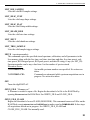
3 Spectrum Directory
Allows you to see the list of spectra in the stored
spectrum memory (Fig. 28). The format is:
sequence# spectrum id month/day hour:minute:second
The bottom of the screen displays a message
saying x# of y# bytes used so you can keep track
of the storage remaining. Use the up and down
arrows to go through the spectra, one page at a
time. Also, you can advance to a particular spectrum by entering its sequence number or spectrum
ID so you don’t have to go through the list.
0 HILL 001 01/01 09:11:08
1 HILL 002 06/28 15:55:21
2 HILL 003 06/28 16:37:37
3 HILL 004 06/28 17:12:29
4 HILL 005 06/28 17:45:15
5 CREEK 1 10/18 09:11:45
6 CREEK 2 10/18 09:22:00
7 CREEK 3 10/19 09:34:51
MORE... > 0
988260 of 1638400 bytes used
Figure 28. Monitor Stored
Spectra.
25
digiDART® Portable HPGe MCA User’s Manual
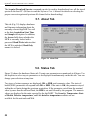
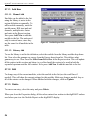
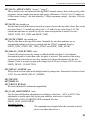
2.2.9. (9) Nuclide Report
The Nuclide Report (Fig. 29) is a very useful tool for
monitoring nuclide count rates and activities in the field.
The report readouts update in real time, for as long as the
report screen is displayed, so you can have a “live” reading
of the selected nuclides. You can select up to 9 gamma-ray
energies located anywhere in the spectrum. The display
shows the nuclide name, the energy, and the calculated
value. The calculated value is the net area times a factor
divided by the live time. The factor is user entered. If you
enter a 1, the value calculated is the net peak count rate.
By including the efficiency and branching ratio in the factor,
the value calculated is the activity.
Nuclide
CO-60
CO-60
CO-57
keV
1332
1173
122
uCi/m2
1.21E01
1.09E01
1.48E00
%
10.2
12.3
86.2
Figure 29. Real-Time Nuclide
Report Display.
See Section 2.2.3 for detailed instructions on setting up the ROIs to be monitored by this report.
26
3. INSTALLATION AND STARTUP
3.1. Software and Hardware Installation
Installing the digiDART and the MAESTRO-32 MCA Emulation Software takes just three easy
steps. (Do not connect the digiDART to your PC until MAESTRO has been installed.)
3.1.1. Install MAESTRO-32 and the CONNECTIONS-32 Driver Update Kit
! Install the accompanying version of MAESTRO-32 (must be v6.04 or higher) according to
the instructions in the MAESTRO Software User’s Manual, selecting the USB-based
instruments hardware option.
! If your MAESTRO CD is accompanied by a CONNECTIONS-32 Driver Update Kit (P/N
797230), follow the installation instructions for the update kit, which supersede the
MAESTRO instructions.
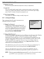
3.1.2. Connect the digiDART to the USB Port on the PC
! With the PC powered on, connect the digiDART to the PC’s USB port.
! Windows will indicate that the digiDART has been detected and will start up the new
hardware installation wizard. Click on Next, indicate that you do not wish to connect to the
internet or the Microsoft website to locate the driver, choose the “automatically locate
driver” option, and follow the remaining prompts to completion. You will now be ready to
run the MCB Configuration program so that MAESTRO and other CONNECTIONS-32
software can recognize the digiDART.
3.1.3. Run the MCB Configuration Program to Build a List of Available Detectors
! From the Windows Start menu, select MAESTRO 32 and MCB Configuration. The MCB
Configuration program will locate all of the (powered on) ORTEC CONNECTIONS-32 MCBs
attached to the local PC and to any network PCs, display a master list of the instruments
found, and allow you to enter customized instrument numbers and descriptions. For complete
instructions on building and customizing this Master Instrument List, see the MAESTRO-32
Software User’s Manual.
3.1.4. Attaching More Than One digiDART to the PC
Once the drivers have been installed for one digiDART, simply attach subsequent units to any
available USB port on the PC or attached USB hub, and re-run the MCB Configuration program.
27
digiDART® Portable HPGe MCA User’s Manual
REMINDER
Be sure to run MCB Configuration any time you add new digiDART (or any
other ORTEC MCBs) to establish communication between the MCBs and the
spectroscopy software.
3.1.5. Connecting to and Disconnecting from the PC
The USB connection allows you to connect digiDARTs to and disconnect them from a USB port
without shutting down MAESTRO, the PC, or the USB hub. Note that if MAESTRO is running
when you disconnect the digiDART, the software will display a “detector not responding”
message on the status line at the bottom of the MAESTRO window. When you reconnect the
digiDART to the PC, simply reselect it from the detector droplist on the MAESTRO Toolbar.
NOTE
When the digiDART is connected to the PC, the keypad will be disabled and the
display will read LCD Display Disabled: Host USB Connected. In this configuration, the
digiDART will function as a standard ORTEC CONNECTIONS-32 MCB.
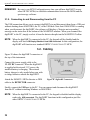
3.2. Cabling
Figure 30 shows the digiDART connectors at
the top of the instrument.
Connect the power supply cable to the
12–15V DC connector. When the digiDART
is supplied with external 12-V power, the
installed battery is charging. The external
battery charger is only needed when you wish
to charge batteries outside the digiDART.
Attach the SMART-1 HPGe detector or DIM
cable to the DETECTOR connector.
Figure 30. digiDART Connectors.
Finally, connect the USB port to the PC. You can connect and disconnect the digiDART
from the PC without restarting Windows or MAESTRO.
NOTE
28
When the digiDART is connected to the PC, the keypad is disabled and the display
reads only USB connected. The digiDART functions in this configuration just like
other ORTEC CONNECTIONS-32 MCBs.
3. INSTALLATION AND STARTUP
3.3. Turning the Power On and Off
To power up the digiDART, press ON/OFF. It takes 3–5 seconds for the spectrum display to
appear. If not connected to a PC, when you turn the unit on but do not press any other key, the
digiDART will wait 10 minutes and shut itself off. This avoids battery drain from accidental
start up.
To turn off the instrument, press ON/OFF again. The digiDART is set up to avoid accidental
power-down so you don’t stop a spectrum in mid-acquisition. The display will ask you to
confirm shutdown. Press 1 to power down or 0 to ignore the shutdown command.
3.4. Changing the Battery
Swapping batteries is easy. Open the battery hatch at the base of the instrument, position the
palm of your hand under the opening, and tap the digiDART’s base gently against your palm.
The battery will dislodge and slide into your hand. Press another battery into place and close the
hatch.
29
digiDART® Portable HPGe MCA User’s Manual
30
4. USING THE DIGIDART IN FIELD MODE
This chapter tells how to configure and operate the digiDART by keypad in field/portable mode.
You can also connect it to a PC and use software such as MAESTRO to set it up and operate it
as a benchtop MCA (see Chapter 5 and the MAESTRO Software User’s Manual).You can only
store spectra in the digiDART memory with the STORE button on the keypad. Spectra acquired
with the digiDART attached to a PC must be stored on the PC or its removable drives. The
InSight Virtual Oscilloscope mode for viewing the pulses can only be accessed via MAESTRO
or similar programs, with the digiDART connected to the PC.
4.1. Normal Operation
This section walks you through the normal steps needed for first-time use of the digiDART in
the field and saving the spectra on the laboratory PC. Once set up, the digiDART saves all the
settings and restores them on the next startup.
On any entry, if you just press MENU/ENTER without pressing any other keys, the current
value will be used, that is, no change will be made. Therefore, if you open a dialog by mistake
you can just press MENU/ENTER to go back without changing anything.
For complete details on the menus and dialogs, refer to Section 2.2. In addition, a quick
reference menu tree is included on the last page of the manual (after the index).
CAUTION The digiDART is splashproof but not watertight. To avoid equipment failure,
protect the unit from prolonged or heavy rainfall and from immersion.
4.1.1. Battery
The battery will last up to 12 hours in full operation with the detector. The battery is charged
internally when external power is supplied. Before starting a series of measurements, you should
check the battery. To check the battery, turn on the digiDART power, press MENU/ENTER,
then (1) View Status. If the percent power is below 15% (1 hour remaining), you should install a
new battery. To remove the battery, turn off the power, open the door at the base of the
instrument, position the palm of your hand under the opening, and tap the digiDART’s base
gently against your palm. The battery will dislodge and slide into your hand. Note the battery
contacts and install the new battery in the same orientation.
If you need to change the battery in the field, you should stop the acquisition and turn off the HV
to the detector, then turn off the power. The acquisition will stop and the HV will turn off as
soon as the battery is removed. However, to maintain the highest spectrum quality you should
stop the acquisition and turn off the detector HV manually. Change the battery, then power up
the digiDART and the detector HV. Wait approximately 2 minutes for the detector to stabilize,
31
digiDART® Portable HPGe MCA User’s Manual
then restart acquisition. To change the battery when external power is connected, it is not
necessary to turn off the digiDART.
4.1.2. Detector
Connect the digiDART to your cooled detector and power on the digiDART. Now set the HV
shutdown mode to protect the detector. Set the shutdown mode by pressing MENU/ENTER,
(6) Adjust Controls, (1) HV Settings, (3) Set Shutdown. For a SMART-1 HPGe Detector,
press (3) SMART; for other types of detectors, select (1) TTL or (2) ORTEC. If the detector
does not have a shutdown signal, use (1) TTL.
Now set the HV to the value for the detector by pressing (2) Set Bias Voltage and entering the
correct value. The polarity is set in the SMART-1 or DIM. Now turn on the HV by pressing
(1) Enable HV. Finally, check all of these operations by pressing (4) to view the HV settings. If
no detector is connected, the readings have no meaning.
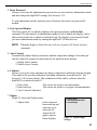
4.1.3. Stored Spectrum Memory
Next check the amount of memory available for stored spectra. Press MENU/ENTER, then (8)
Spectrum Memory, (3) Spectrum Directory to display the contents and remaining capacity of
the stored-spectrum memory. The display format is:
sequence#, Identifier, start month and day, start time
The bottom of the screen displays a message saying x# of y# bytes used. If you expect to need
more than the remaining storage space, you must clear out the existing spectra. If you want to
save these spectra, you must download them to PC. After download, clear the digiDART
memory by pressing MENU/ENTER, (8) Spectrum Memory, then (2) Erase All.
If no more stored-spectrum memory is available, you can, if you wish, collect a final spectrum
and leave it stored in RAM. Once you've docked to the host PC, download that final spectrum
first, then download the spectra from stored spectrum memory.
4.1.4. Spectrum Status Parameters
The digiDART displays two data-acquisition parameters in real time at the top of the spectrum
(see the top of Fig. 31, page 36). To set up this status line, press MENU/ENTER and press
(4) Status Line to display the numbered list of parameters.
1 Cursor location (energy)
2 Cursor location (channel)
32
4. USING THE DIGIDART IN FIELD MODE
3
4
5
6
7
8
9
0
Live time
Real time
Live time remaining
Real time remaining
Battery time remaining
Count rate
Count rate in ROI
Counts
If any parameters are currently selected, they will be indicated by a 1* or 2* before the
parameter number. If you like these settings, press MENU/ENTER. To remove a setting (with
1* or 2*), press the parameter number. To add a setting, press the parameter number. If no
parameters are set, the first one selected becomes 1*. If one parameter is selected, the next one
selected becomes the other number. The 1* parameter is shown on the left of the display and
the 2* is shown on the right. As an example for use in later steps, select (2) for 1* and (3) for 2*.
Press MENU/ENTER to return to the Main Menu.
4.1.5. ADC
For HPGe detectors the spectrum size is normally 8K or more channels, and for NaI the
spectrum size is normally 512, 1024 or 2048 channels. To set the number of channels (or
conversion gain), press MENU/ENTER, (6), (4), then (1). Now press (6) for a conversion gain
of 16384 channels. Press (2) and set the LLD to 50 (this is in channels). Press (3) and set the
ULD to 16380. To turn off the gate, press (4) and (1). Press (5) to view the settings you just
made to verify they are correct. Press MENU/ENTER 4 times to return to the spectrum display.
4.1.6. Amplifier
Now you need to set the amplifier to the proper settings. First, set the polarity for the input to
match the output of the detector. GEM detectors have positive output and GMX, LEPS, and
LOAX detectors have negative output. Press MENU/ENTER, (6), then (2) to show the menu of
amplifier settings. Press (1) and then (2). Press MENU/ENTER 3 times to return to the
spectrum display. Press <8+9> to show the complete spectrum. Put a known source (such as
137
Cs or 60Co) in front of the detector, and press STOP, CLEAR, then START to begin
collecting a spectrum. You should see a spectrum in the display and see the live time on the
upper right.
If the peaks are not where you want them in the spectrum, press MENU/ENTER, (6), (2), and
then (1) or (2) depending on how far from ideal the peaks are. Then adjust the gain to a lower or
higher value. Press MENU/ENTER 3 times to return to the spectrum display, then press STOP,
33
digiDART® Portable HPGe MCA User’s Manual
CLEAR, and START to collect another spectrum. Adjust again if needed or continue with the
next step.
4.1.7. Rise Time and Flattop
The rise time should be set for the count rate and resolution you expect. Of course, you can’t
improve the resolution beyond the capabilities of the detector, but you can adjust the digiDART
setting for the best resolution at any count rate. For most field work, the rise time is set to 12 and
the flattop is set to 1. This corresponds to the analog shaping time constant of 6 microseconds,
which is the setting used for detector test and specification. If the count rate is expected to be
high, then shorter rise times and flattops can be selected, which will increase the FWHM.
To set the rise time, press MENU/ENTER, (6), (2), (3), then enter the rise time. The rise time is
a decimal number. If you don’t enter one of the exact values (say you enter 11.3), the digiDART
selects the closest value (e.g., 11.4). Now set the flattop by pressing (4), then the flattop. The
flattop is a decimal number. If you don’t enter one of the exact values (suppose you enter 1.1),
the closest value is selected (e.g., 1.2). You can view the settings now by selecting (0). Press
MENU/ENTER 3 times to return to the spectrum display.
4.1.8. Optimize
The next step is to optimize the detector (see Section for a detailed discussion of this operation).
Optimization adjusts the pole zero and the flattop tilt for the best resolution for the detector. Use
a source positioned so the detector count rate is approximately 5000 cps. To monitor the count
rate, display it as one of the status line options as discussed in Section 4.1.4. When the count rate
is satisfactory, press MENU/ENTER, (6), (2), (7), then (1) to start the optimization. The display
will show that the optimization is underway. The progress is shown by a series of dots. If you
need to stop the process because of no counts or too high a count rate, press any key to abort. If
you abort, you must fix the problem and redo the optimization before collecting any spectra.
Press MENU/ENTER to return to the Amplifier dialog. It is not necessary to do the pole zero
step, as this is done automatically during optimize. Press MENU/ENTER 3 times to return to
the spectrum display.
4.1.9. Detector State of Health
Press STOP. Now you can view the SMART-1 HPGe Detector state of health to check what has
happened during the last acquisition. To check the detector SOH, press MENU/ENTER, (6),
(1), (5) View HV SOH. This will display the status of the nine SOH bits as shown in Table 2.
The Values are cleared on each START and set on each STOP. Press MENU/ENTER 4 times to
return to the spectrum display.
34
4. USING THE DIGIDART IN FIELD MODE
Table 2. State-of-Health Bit Definitions.
Bit
Description
Comment
0
+24V
1
+12V
2
-12 V
3
-24V
4
Temperature
Set if the detector temperature increases and shuts down the HV (therefore, the
SHUT bit will also be set).
5
HV voltage
Set if the high voltage deviates ±300 V from the value you entered in (6) Adjust
Controls/(2) Set Bias Voltage.
6
Overload
Set if the preamplifier overloads for more than about 4.0 seconds.
7
Shutdown
Set if the preamplifier shuts down for any reason.
8
Security
9
Power
The first four bits monitor the voltages coming from the digiDART. If one of these
values varies by ±2 V, the corresponding bit is set.
At the start of the acquisition, the digiDART queries the Smart-1 HPGe Detector
for its serial number. The digiDART then writes a random number to the Smart-1
HPGe Detector. At the end of the acquisition, both numbers are read from the
Smart-1 HPGe Detector and compared to the original values. If there is a
mismatch, the Security SOH bit is set.
Set if the power fails during an acquisition.
4.1.10. Calibration
Now set up a two-point (linear fit) calibration. First, collect a spectrum or use the one collected
above. Locate the peaks in the spectrum for the source. Use the left or right arrow to scroll the
cursor to the first peak. Record the cursor channel as shown in the upper left corner of the
display. Now put the marker on the second peak. Now find the slope by dividing the difference
between the two energies by the difference between the two channel values. This is the slope. To
enter the slope, press MENU/ENTER, select (7) General Settings, (6) Calibrate, then (1), now
enter the slope. To calculate the intercept, multiply the slope by the low channel number.
Subtract this value from the low energy. This is the intercept. Press (2) and enter the intercept.
This linear calibration is used in the Peak calculation for the Nuclide Report (see Section 6.1.1).
For example, for a 60Co spectrum, the 1173 peak is in channel 7241 and the 1332 peak is in
8226. This gives (1173!1332)/(7241!8226) or 0.1614 for the slope and 1173!(0.1614*7241) or
4.148 for the zero intercept. The zero intercept is the energy of channel 0 in the spectrum.
35
digiDART® Portable HPGe MCA User’s Manual
Select (3) to show the current slope and intercept. Press MENU/ENTER 4 times to show the
spectrum.
NOTE
The most recently entered calibration (from either software or the digiDART) will be
written into the stored spectrum memory when the spectrum is stored. The calibration
will remain with the spectrum when it is downloaded to the PC and stored as an .SPC
file.
4.1.11. Display Energy
Now select MENU/ENTER, then (4) to show the current status line selections. Press (2) to
remove the marker channel and press (1) to display the marker energy. Press MENU/ENTER
2 times to return to the spectrum display.
4.1.12. Setting ROIs in the Spectrum Display
The digiDART lets you mark any number of
ROIs on the spectrum display. They are shown
as horizontal lines immediately beneath the
spectrum (Fig. 31). Any ROIs saved with the
spectrum are displayed when the spectrum is
viewed in MAESTRO, ScintiVision, etc. Note
that these are not the same as the ROIs for the
Nuclide Report discussed in Section 4.1.15.
To set an ROI in the spectrum mode, put
the marker on the starting channel and press
<8+3>, then move the marker to the end
channel and press <8+6>.
Figure 31. ROI Indicator Lines.
The ROI is shown by a bar below the spectrum. The bar will always be shown, even if it is a
small region in a condensed display.
To delete an ROI, put the marker in the ROI and press <8+4>.
4.1.13. Presets
To set a preset to stop the collection at a specific point, press MENU/ENTER, (6), (3), then the
number of the preset type you want. For example, to set the Live time preset, press (1) now and
enter the preset value in seconds. The value is a decimal number with resolution of
20 milliseconds. The entered value is truncated to the nearest valid value.
36
4. USING THE DIGIDART IN FIELD MODE
To turn off a preset, enter a 0 (not a blank), then MENU/ENTER. Entering a blank or nothing
then pressing MENU/ENTER will keep the existing preset.
Press (7) to view the live, real, count and integral preset settings. The uncertainty and MDA
settings are viewed on their own separate displays. Press MENU/ENTER 4 times to return to
the spectrum display.
The MDA preset is used to stop the counting when all of the nuclide MDAs are met. The MDA
setup process is discussed on page 18. The MDA preset requires the detector efficiency and
nuclide branching ratio, both of these can easily be found or calculated with software such as
GammaVision.
4.1.14. Stabilizers
The digiDART is very stable, so unless you see peak drift the stabilizers can be turned off or
disabled. To disable the stabilizers, press MENU/ENTER, (6), (5), then (7) to show the current
state. If both show as DISABLED, press MENU/ENTER 4 times to return to the spectrum
display. If either or both are enabled, press MENU/ENTER, then (1) for gain to disable it, or (4)
to disable zero. Then press MENU/ENTER 3 times to return to the spectrum display.
4.1.15. Nuclide Report
The Nuclide Report is a very useful tool for monitoring nuclide count rates and activities in the
field. The report readouts update in real time, for as long as the report screen is displayed, so you
can have a “live” reading of the selected nuclides. You can select up to 9 gamma-ray energies
located anywhere in the spectrum. The display shows the nuclide name, the energy, and the
calculated value. The calculated value is the net area times a factor divided by the live time. The
factor is user entered. If you enter a 1, the value calculated is the net peak count rate. By
including the efficiency and branching ratio in the factor, the value calculated is the activity.
To set up the ROIs to be monitored on the Nuclide Report screen, see Section 2.2.3.
To view the Nuclide Report from the spectrum screen, press MENU/ENTER, (9).
4.1.16. Administrator and User Passwords
The digiDART offers two levels of password security: user and administrator. The user
password prevents any unauthorized startup of the instrument. The administrator password
prevents non-administrators from changing the current digiDART settings, but allows them to
set and enable the detector high voltage, START and STOP data acquisition, monitor hardware
37
digiDART® Portable HPGe MCA User’s Manual
status, and view the Nuclide Report. Note that spectrum locking (Section 4.1.16) only works
when an administrator password is set.
! The passwords are numerical, and are one or more characters in length (but cannot be a
single zero).
! Assigning a single zero (0) as the password is the “remove password” command.
! After assigning the password(s), power the digiDART off/on to ensure they are in effect.
! If the user password is set, the digiDART will prompt for the password when the unit is
started up.
! If both a user and administrator password have been activated, either the user password or
the administrator password can be entered at startup. If you enter it correctly, the password
screen closes and the digiDART goes to spectrum mode (unless the spectrum is locked and
you have only user access). If not correct, an “Access denied” message is displayed. If the
spectrum is locked, a text message will be shown at startup to indicate that the password was
accepted.
! Once the administrator password is set, you must enter the administrator password to change
passwords.
! To exit the administrator level, cycle the power off/on.
Table 3 summarizes how the two passwords work.
Table 3. digiDART-LF Passwords.
Password(s) set
Required on
startup?
Required to adjust setup controls?
User pwd only
Yes
No (full access granted)
Admin pwd only
No
Yes
User and Admin pwds*
One of the two
If only User pwd entered, no access to setup controls
If Admin pwd entered, full access granted
* If the user and administrator passwords are identical, entering the password grants full administrator access.
To set or change the user password, press MENU/ENTER, (7) General Settings, (1) Change
User Password. Now enter the number(s) you wish to assign as the password. If you make a
38
4. USING THE DIGIDART IN FIELD MODE
mistake, press CLEAR to erase the preceding character. When finished, press MENU/ENTER
to return to the General Settings menu. To remove the password, enter a single 0, then
MENU/ENTER.
To set or change the administrator password from spectrum display mode, press,
MENU/ENTER (7) General Settings, (2) Change Administrator Password, then enter the
number(s) you wish to assign as the password. If you make a mistake, press CLEAR to erase the
preceding character.
When finished, press MENU/ENTER to return to the General Settings menu.
To enter the administrator password and go to the administrator level, from the spectrum display,
press MENU/ENTER, (7), (3) Enter Password, enter the number string, and press
MENU/ENTER. When you enter it correctly, the password display closes and returns to the
Main Menu. If incorrect, an “Access denied” message is displayed.
If you do not know the password, press MENU/ENTER to clear the “Access denied” message
and return to the Main Menu.
NOTE There is no master administrator password. If you lose this password, contact your
ORTEC service representative or our Global Service Center.
4.1.17. Locking the Spectrum Display
For use in sensitive areas, the spectrum display can be locked so that it can only be viewed by an
administrator (e.g., an administrator password must be set for this feature to work). When the
administrator locks the spectrum display, the spectrum screen shows a “locked” message and the
(5) Peak Info function is not available. However, the operator can still view the Nuclide Report.
To lock the display, enter the administrator password, then go to the Main Menu, press (7)
General Settings, (4) Lock Spectral Display, then (1) LOCK. The “Display Locked” message
will be displayed. Press MENU/ENTER 2 times to return to the General Settings menu. Now
power off the digiDART. On next startup, the display will be locked and can only be unlocked
by an administrator.
To unlock the display, in administrator mode go to the Main Menu, press (7) General Settings,
(4) Lock Spectral Display, then (1) UNLOCK. The “Display Unlocked” message will be
displayed. Press MENU/ENTER 2 times to return to the General Settings menu.
Table 4 summarizes how passwording interacts with spectrum locking.
39
digiDART® Portable HPGe MCA User’s Manual
Table 4. Passwords and Spectrum Locking.
Spectrum locked (effect is
immediate if admin pwd set)
Spectrum displayed?
No pwd set
Yes
Only User pwd set
Yes
Only Admin pwd set
No; must enter Admin pwd to display spectrum
Both User and Admin pwds set*
If only User pwd entered, spectrum not displayed
If Admin pwd entered, spectrum displayed
* If the user and administrator passwords are identical, entering the password grants full administrator access
and spectrum is displayed.
NOTE
When the display is locked, the digiDART will not communicate with PC-based
spectroscopy applications. To restore communication with the PC software you must
unplug the USB cable, enter the administrator password, unlock the display, then
reconnect the USB cable.
4.1.18. Collecting Spectra
You are now ready to collect spectra. When you have collected the first spectrum, it can be
saved in the digiDART’s internal, stored-spectrum memory. To save the spectrum, press
STORE, enter the 8-character spectrum ID to be stored with the spectrum, then press
MENU/ENTER. The current ID is displayed. To use this, just press MENU/ENTER. The same
ID can be used in multiple spectra. On the ID entry dialog, you are also shown the amount of
memory used and the amount used for this spectrum. When the memory is full, a warning is
displayed. The next dialog asks you to confirm that you want to store this spectrum. Press (1) to
store or (2) to skip the storage process. An individual spectrum cannot be erased from the stored
spectrum memory.
The list of stored spectra is shown, from the spectrum display, by pressing MENU/ENTER, (8),
(3). The list is shown by sequence number, ID, and date/time. To show any particular spectrum,
enter the sequence number. For sequence numbers above 9, enter the first digit, then the second
digit, then the other digits. Depending on how quickly you enter the two or more digits, the
display may update with different lists. For example, to select spectrum 351:
! Press (3) and pause; the page with spectrum 3 at the top will be displayed.
! Next press (5) and pause; now the page with spectrum 35 at the top will be displayed.
! Now press (1) to show the page with spectrum 351 at the top.
40
4. USING THE DIGIDART IN FIELD MODE
To browse through all the spectra, use the down arrow key to display the next group of 8 spectra
and the up arrow key to display the previous group of 8.
4.1.19. Downloading Spectra to the PC
After you have collected the spectra and stored them in the digiDART stored-spectrum memory,
you can download them to a PC disk storage. The download of the spectra is controlled by PCbased software such as MAESTRO. Typically, the software allows you to download the spectra
one at a time or all at one time automatically. See the software user’s manual for details on
downloading and saving the spectra.
When connected to the PC, the digiDART displays a “USB Connected” message. Otherwise, the
display and keypad are disabled. Every function is available to the software dialogs except the
ability to store spectra, enter or change the digiDART user and administrator passwords, and
display locking. MAESTRO, GammaVision, and other ORTEC programs have detector-locking
commands that prevent unauthorized users from changing detector settings, starting and
stopping data acquisition, and clearing the detector memory. These commands function
separately from the digiDART’s user and administrator passwords. If the digiDART is locked by
software, it can be used in the field without knowing the password, but cannot be reconnected to
a PC and its memory erased unless the user knows the password.
4.2. Should You Take a Laptop Into the Field?
The digiDART is designed so that you don’t need a PC to operate it, especially in the field. But,
there are a few situations where a laptop is of use in field operations. One use is for advanced
analysis of the spectra where the Nuclide Report does not show enough detail. In this case,
software such as GammaVision or M-1 can be used to process the spectra “on the spot.” The
second is to provide storage for more spectra than the digiDART stored-spectrum memory
capacity (see Table 1, page 3). A laptop with MAESTRO will allow you to periodically transfer
spectra from the digiDART and clear its spectrum memory so you can continue data collection.
4.2.1. Operation with a PC
The details of the operation of the digiDART by the PC software depend on the software itself.
ORTEC software, such as MAESTRO, is described in the manual for the software. In general,
the digiDART operates very much like other ORTEC MCBs using CONNECTIONS-32. The
digiDART is a modern digital signal processor with all the settings, controls, and adjustments
controllable by software. To use it with your own software, we recommend using the
CONNECTIONS-32 Programmer’s Toolkit with Microsoft ActiveX® Controls (A11-B32). The
commands are given in Chapter 8. For use with handheld computers without Windows, the
low-level commands are given in Section 8.2.
41
digiDART® Portable HPGe MCA User’s Manual
4.3. Troubleshooting
4.3.1. If You Disconnected While In InSight Virtual Oscilloscope Mode
If digiDART was in InSight mode when you disconnected it from the PC, it will stay in InSight
mode until it is changed. You must switch the digiDART out of InSight mode to collect data. If
the spectrum display is unlocked, the digiDART will display the message, Display enabled, not in
PHA mode. To return to PHA mode, click on MENU/ENTER, (7) Display, (2) Set Display
Mode=PHA. If the spectrum display is locked, enter the administrator password, then (2) Set
Display Mode = PHA.
4.3.2. The digiDART Will Not Turn on
Replace the battery or connect to external power. Check that the battery is properly installed.
4.3.3. If You Forgot the Password
If you have forgotten the user password, start the digiDART, enter the administrator password,
and enter a a new user password. If there is no administrator password or you have forgotten it,
too, contact your ORTEC service representative.
4.3.4. MAESTRO Does Not Connect with the digiDART
If properly installed and functioning MAESTRO software (or other CONNECTIONS-32 programs)
cannot find and communicate with the digiDART, check the following:
! The digiDART is not turned on.
! The USB cable is not properly connected.
! The digiDART display is locked.
! The Master Instrument List on the PC does not include the digiDART. Run the MCB
Configuration program as discussed in Section 3.1.3 or the MAESTRO Software User’s
Manual.
If this does not resolve the communication issue, contact our Global Service Center.
42
5. USING THE DIGIDART WITH MAESTRO
The digiDART is intended for completely independent operation, with no PC required.
However, when you connect it to a PC running ORTEC CONNECTIONS-32 spectroscopy
applications, such MAESTRO or ScintiVision you can use it as a high-performance
spectrometer/digital MCA. When you disconnect from the PC, any changes you have made to
the hardware settings via PC will remain in effect until changed from the keypad.
Be sure to install the accompanying MAESTRO-32 MCA Emulator application and, if supplied,
the CONNECTIONS-32 Driver Update Kit. These contain the most up-to-date drivers for the
digiDART and other ORTEC hardware. If you have any questions about software/hardware
compatibility, contact your ORTEC representative or our Global Service Center. The
MAESTRO Software User’s Manual contains complete instructions on software installation and
configuration of the MCBs attached to your PC. When installing MAESTRO, choose the USBBased Instruments selection to install the correct driver for the digiDART.
The rest of this chapter discusses the hardware setup dialog you will see within MAESTRO,
ScintiVision, and all other ORTEC CONNECTIONS-32 software when you click on
Acquire/MCB Properties.... When the digiDART is connected to the PC, it is completely
software controlled. The MCB Properties dialog contains all of the instrument controls including
ADC setup parameters, acquisition presets, amplifier gain adjustments, pole-zero controls, and
access to the InSight Virtual Oscilloscope. Just move from tab to tab and set your hardware
parameters, then click on Close — it’s that easy.
Note that as you enter characters in the data-entry fields, the characters will be underlined until
you move to another field or until 5 seconds have lapsed since a character was last entered.
During the time the entry is underlined, no other program or PC on the network can modify this
value.
5.1. Amplifier Tab
Figure 32 shows the controls on the Amplifier tab. It the controls for Gain, Baseline Restore,
Preamplifier Type, Input Polarity, and optimization. Be sure that all of the controls on the tabs
have been set before clicking the Start Auto (optimize) button.
NOTE
The changes you make on this tab take place immediately. There is no cancel or undo
for this dialog.
Gain — Set the amplifier coarse gain by selecting from the Coarse droplist, then adjust the Fine
gain with the horizontal slider bar or the edit box, in the range of 0.45 to 1.00. The resulting
effective gain is shown at the top of the Gain section. The two controls used together cover the
entire range of amplification from 0.45 to 100.
43
digiDART® Portable HPGe MCA User’s Manual
The Input Polarity radio buttons
select the preamplifier input signal
polarity for the signal from the
detector. Normally, GEM (p-type)
detectors have a positive signal and
GMX (n-type) have a negative signal.
The Baseline Restore is used to return
the baseline of the pulses to the true
zero between incoming pulses. This
improves the resolution by removing
low frequency noise such as dc shifts
or mains power ac pickup. The baseline settings control the time constant
Figure 32. Amplifier Tab.
of the circuit that returns the baseline
to zero. There are three fixed choices (Auto,3 Fast, and Slow). The fast setting is used for high
count rates, the slow for low count rates. Auto adjusts the time constant as appropriate for the
input count rate. The settings (auto, fast, or slow) are saved in the digiDART even when the
power is off. The time constant can be manually set on the InSight display (see the InSight
discussion in the MAESTRO Software User’s Manual).
You can view the time when the baseline restorer is active on the InSight display as a Mark
region (see the discussion on Marks in the Software User’s Manual). In the automatic mode, the
current value is shown on the InSight sidebar. For a low-count-rate system, the value will remain
at about 90.
Preamplifier Type — The digiDART uses Resistive Feedback preamplifiers.
Optimize — The digiDART is equipped with both automatic pole-zero logic? and automatic
flattop logic.? The Start Auto optimization button uses these features to automatically choose
the best pole zero and flattop tilt settings. Note that if you selected Transistor Reset as the
Preamplifier Type for this digiDART, the Start Auto button does not perform the pole zero.
As with any system, the digiDART should be optimized any time the detector is replaced or if
the flattop width is changed. For optimization to take place, the digiDART must be processing
pulses. The detector should be connected in its final configuration before optimizing. Position a
source such that the input count rate is approximately 5000 cps. Monitor the count rate with
either the Peak Info or Input Count Rate command.
3
U.S. Patent 5,912,825.
44
5. USING THE DIGIDART WITH MAESTRO
Click on Start Auto. The optimize command is sent to the digiDART at this time and, if the
digiDART is able to start the operation, a series of short beeps sounds to indicate that
optimization is in progress. When optimizing is complete, the beeping stops.
During optimization, pole zeroes are performed for several rise-time values and the digiDART is
cycled through all the rise time values for the determination of the optimum tilt values. As all of
the values for all the combinations are maintained in the digiDART, the optimize function does
not need to be repeated for each possible rise time. The optimization can take from 1 to 10
minutes depending on count rate.
You should repeat the optimization if the flattop width is changed.
The effect of optimization on the pulse can be seen in the InSight mode, on the Amplifier 2 tab.
Note, however, that if the settings were close to proper adjustment before starting optimization,
the pulse shape might not change enough for you to see. (In this situation, you also might not
notice a change in the shape of the spectrum peaks.) The most visible effect of incorrect settings
is high- or low-side peak tailing or poor resolution.
5.2. Amplifier 2 Tab
Figure 33 shows the Amplifier 2
tab, which accesses the advanced
digiDART shaping controls
including the InSight Virtual Oscilloscope mode, which is discussed
in the MAESTRO Software User’s
Manual.
The many choices of Rise Time
allow you to precisely control the
tradeoff between resolution and
throughput. The MAESTRO manual
discusses this tradeoff and contains
a guide to choosing rise time accordFigure 33. Amplifier 2 Tab.
ing to count rate. The value of the rise
time parameter in the digiDART
is roughly equivalent to twice the integration time set on a conventional analog spectroscopy
amplifier. Thus, a digiDART value of 12 µs corresponds to 6 µs in a conventional amplifier.
Starting with the nominal value of 12.0, you should increase values of the rise time for better
resolution for expected lower count rates, or when unusually high count rates are anticipated,
reduce the rise time for higher throughput with somewhat worse resolution.
45
digiDART® Portable HPGe MCA User’s Manual
Use the up/down buttons to adjust the rise time within the range of 0.2 µs to 23.0 µs. The most
recent settings are saved in the digiDART firmware even when the power is turned off.
For the more advanced user, the InSight mode allows you to directly view all the parameters and
adjust them interactively while collecting live data. To access the InSight mode, go to the
InSight section and click on Start.
The Rise Time value is for both the rise and fall times; thus, changing the rise time has the
effect of spreading or narrowing the quasi-trapezoid symmetrically.
The Flattop controls adjust the top of the quasi-trapezoid. The Width adjusts the extent of the
flattop (from 0.3 to 2.4 µs). The Tilt adjustment varies the “flatness” of this section slightly. The
Tilt can be positive or negative. Choosing a positive value results in a flattop that slopes
downward; choosing a negative value gives an upward slope. Alternatively, the optimize feature
on the Amplifier tab can set the tilt value automatically. This automatic value is normally the
best for resolution, but it can be changed on this dialog and in the InSight mode to accommodate
particular throughput/resolution tradeoffs. The optimize feature also automatically adjusts the
pole-zero setting.
The dead time per pulse is
In the Pole Zero section, the Start button performs a pole zero at the specified rise time and
other shaping values. Unlike the optimize feature, it performs a pole zero for only the one rise
time. The pole-zero Stop button aborts the pole zero, and is normally not used.
When you are satisfied with the settings, Close the Properties dialog and prepare to acquire data.
Once data acquisition is underway, the advanced user might wish to select MCB Properties...
and click on the InSight section’s Start button to adjust the shaping parameters interactively
with a “live” waveform showing the actual pulse shape, or just to verify that all is well. Section ?
provides detailed instructions on using the InSight mode.
5.3. ADC Tab
This tab (Fig. 34) contains the Gate, Conversion Gain, Lower Level Discriminator, and Upper
Level Discriminator controls. In addition, the current real time, live time, and count rate are
monitored at the bottom of the dialog.
46
5. USING THE DIGIDART WITH MAESTRO
Gate — This control allows you to
select a logic gating function. With
this function Off, no gating is performed (that is, all detector signals
are processed); with the function in
Coincidence, a gating input signal
must be present at the proper time
for the conversion of the event; in
Anticoincidence, the gating input
signal must not be present for the
conversion of the detector signal. The
gating signal must occur prior to and
extend 500 nanoseconds beyond peak
detect (peak maximum).
Figure 34. ADC Tab.
Conversion Gain — Sets the maximum
channel number in the spectrum. If set to 16384, the energy scale will be divided into 16384
channels. The conversion gain is entered in powers of 2 (e.g., 8192, 4096, 2048, ...). The
up/down arrow buttons step through the valid settings for the digiDART.
Upper- and Lower-Level Discriminators — The Lower Level Discriminator sets the level of
the lowest amplitude pulse that will be stored. This level establishes a lower-level cutoff, by
channel number, for ADC conversions. Setting that level above random noise increases useful
throughput because the MCB is not unproductively occupied processing noise pulses. The
Upper Level Discriminator sets the level of the highest amplitude pulse that will be stored. This
level establishes an upper-level cutoff, by channel number, for ADC conversions.
5.4. Stabilizer Tab
The digiDART has both a gain stabilizer and a zero stabilizer. These are discussed in detail in
Sections 6.3 and 6.4.
The Stabilizer tab (Fig. 35) shows the current values for the stabilizers. The value in each
Adjustment section shows how much adjustment is currently applied. The Initialize buttons set
the adjustment to 0. If the value approaches 90% or above, the amplifier gain should be adjusted
so the stabilizer can continue to function — when the adjustment value reaches 100%, the
stabilizer cannot make further corrections in that direction. The Center Channel and Width
fields show the peak currently used for stabilization.
47
digiDART® Portable HPGe MCA User’s Manual
To enable the stabilizer, enter the
Center Channel and Width values
manually or click on the Suggest
Region button. Suggest Region reads
the position of the marker and inserts
values into the fields. If the marker is
in an ROI, the limits of the ROI are
used. If the marker is not in an ROI,
the center channel is the marker
channel and the width is 3 times the
FWHM at this energy. Now click on
the appropriate Enabled checkbox to
turn the stabilizer on. Until changed
in this dialog, the stabilizer will stay
Figure 35. Stabilizer Tab.
active even if the power is turned off.
When the stabilizer is enabled, the
Center Channel and Width cannot be changed.
5.5. High Voltage Tab
Figure 36 shows the High Voltage tab,
which allows you to turn the high
voltage on or off, set and monitor the
voltage, and choose the Shutdown
mode.
The high voltage is overridden by the
detector bias remote shutdown signal
from the detector; high voltage cannot
be enabled if the remote shutdown or
overload signals prevent it. If an
Overload indicator is displayed, there
is a bad connection in your system. If
a Shutdown indicator is displayed,
either the detector is warm or you have
chosen the wrong shutdown mode.
Figure 36. High Voltage Tab.
Enter the detector high voltage in the Target field, click On, and monitor the voltage in the
Actual field. Click the Off button to turn off the high voltage.
48
5. USING THE DIGIDART WITH MAESTRO
The shutdown can be ORTEC, TTL or SMART. The ORTEC mode is used for all ORTEC
detectors except SMART-1 detectors; use the SMART option for those detectors. Check with
the detector manufacturer for other detectors. The TTL mode is used for most non-ORTEC
detectors.
The high voltage in the digiDART is supplied by the SMART-1 module or in a separate DIM.
The recommended HV for SMART-1 is displayed on the dialog. For other detectors, see the
detector manual or data sheet for the correct voltage. The polarity is determined by the DIM or
SMART-1 module.
5.6. Field Data Tab
This tab (Fig. 37) is used to view the
digiDART spectra collected in
Field Mode, that is, in remote mode,
detached from a PC. The digiDART
is always in Field Mode when disconnected from the PC. The spectrum can
then be viewed as the “active” spectrum in the digiDART. The active
spectrum is the spectrum where the
new data are collected. The current
active spectrum is lost.
The lower left of the tab shows the
total number of spectra (not counting
Figure 37. Field Data Tab.
the active spectrum) stored in the
digiDART memory. The spectrum ID
of the active spectrum is shown in the lower right. The spectrum ID is the eight-character
alphanumeric value stored with the spectrum. The stored spectra cannot be viewed or stored in
the PC until they are moved to the active spectrum position.
To move a spectrum from the stored memory to the active memory, enter the spectrum number
and click on Move. Use the up/down arrow buttons to scroll through the list of spectra. The label
on the lower right does not update until a spectrum is moved. The numbers are the same as the
numbers shown on the digiDART display in the stored spectrum list. Note that this only moves
the spectrum inside the digiDART. To save the current active spectrum to the PC disk, use the
File/Save commands in the PC-based application.
49
digiDART® Portable HPGe MCA User’s Manual
The Acquire/Download Spectra command can also be used to download and save all the stored
spectra to the host PC. (Be sure to read the Software User’s Manual for details on selecting the
proper conversion gain and spectrum file format before downloading.)
5.7. About Tab
This tab (Fig. 38) displays hardware
and firmware information about the
currently selected digiDART as well
as the data Acquisition Start Time
and Sample description. In addition,
the Access field shows whether the
MCB is currently locked with a
password. Read/Write indicates that
the MCB is unlocked; Read Only
means it is locked.
Figure 38. About Tab.
5.8. Status Tab
Figure 39 shows the hardware Status tab. Twenty-one parameters are monitored at all times. Use
the droplists to select any six parameters to be displayed simultaneously on the this tab. You can
change your selections at any time.
Two types of status responses are displayed: OK or ERR, and a numeric value. The state-ofhealth (SOH) parameters all respond with OK or ERR. If the state is OK, the parameter stayed
within the set limits during the spectrum acquisition. If the parameter varied from the nominal
value by more than the allowed limit, the ERR is set until cleared by the program. The numeric
values are displayed in the units reported by the digiDART. The Security, Temperature State
of Health, Detector temperature, and Live detector temperature readouts are not
available for this unit and read N/A.
50
5. USING THE DIGIDART WITH MAESTRO
The parameters are:
Detector State of Health
This is OK if all the SOH are OK
and ERR if any one is ERR.
DIM +24V State of Health
This is OK if the +24 volt supply
in the DIM has stayed within
200 mV of +24 volts since the
last time the SOH was cleared.
DIM +12V State of Health
This is OK if the +12 volt supply
in the DIM has stayed within
200 mV of +12 volts since the
last time the SOH was cleared.
Figure 39. Status Tab.
DIM -12V State of Health
This is OK if the !12 volt supply in the DIM has stayed within 200 mV of !12 volts since
the last time the SOH was cleared.
DIM -24V State of Health
This is OK if the !24 volt supply in the DIM has stayed within 200 mV of !24 volts since
the last time the SOH was cleared.
Temperature State of Health
Not available for the digiDART.
High Voltage State of Health
This is OK if the HV supply in the DIM has stayed within 200 V of specified bias voltage
since the last time the SOH was cleared.
Shutdown State of Health
This is OK if the detector shutdown has not activated since the last time the SOH was
cleared.
Preamplifier overload State of Health
This is OK if the preamplifier overload has not activated since the last time the SOH was
cleared.
51
digiDART® Portable HPGe MCA User’s Manual
Security State of Health
Not available for the digiDART.
Power State of Health
This is OK if the power to the DIM was constant during the last spectrum acquisition.
+24 volts
This is the current value of the +24 volt supply in the DIM as delivered to the detector.
+12 volts
This is the current value of the +12 volt supply in the DIM as delivered to the detector.
!12 volts
This is the current value of the !12 volt supply in the DIM as delivered to the detector.
!24 volts
This is the current value of the !24 volt supply in the DIM as delivered to the detector.
High Voltage
This is the current value of the high-voltage bias supply in the DIM as delivered to the
detector.
Detector temperature
Not available for the digiDART.
Live detector temperature
Not available for the digiDART.
Battery voltage
This is the present voltage of the internal battery.
Battery % full
This is an estimate of the amount of power remaining in the battery.
Battery time remaining
This is an estimate of the time remaining when using the internal battery operating in the
current mode.
52
5. USING THE DIGIDART WITH MAESTRO
5.9. Presets Tab
Figure 40 shows the Presets tab. MDA
presets are shown on a separate tab.
The presets can only be set on an
MCB that is not acquiring data
(during acquisition the preset field
backgrounds are gray indicating that
they are inactive). You can use any
or all of the presets at one time. To
disable a preset, enter a value of zero.
If you disable all of the presets, data
acquisition will continue until
manually stopped.
Figure 40. Presets Tab.
When more than one preset is
enabled (set to a non-zero value), the first condition met during the acquisition causes the MCB
to stop. This can be useful when you are analyzing samples of widely varying activity and do not
know the general activity before counting. For example, the Live Time preset can be set so that
sufficient counts can be obtained for proper calculation of the activity in the sample with the
least activity. But if the sample contains a large amount of this or another nuclide, the dead time
could be high, resulting in a long counting time for the sample. If you set the ROI Peak preset in
addition to the Live Time preset, the low-level samples will be counted to the desired fixed live
time while the very active samples will be counted for the ROI peak count. In this circumstance,
the ROI Peak preset can be viewed as a “safety valve.”
The values of all presets for the currently selected MCB are shown on the Status Sidebar. These
values do not change as new values are entered on the Presets tab; the changes take place only
when you Close the Properties dialog.
Enter the Real Time and Live Time presets in units of seconds and fractions of a second. These
values are stored internally with a resolution of 20 milliseconds (ms) since the MCB clock
increments by 20 ms. Real time means elapsed time or clock time. Live time refers to the amount
of time that the MCB is available to accept another pulse (i.e., is not busy), and is equal to the
real time minus the dead time (the time the MCB is not available).
Enter the ROI Peak count preset value in counts. With this preset condition, the MCB stops
counting when any ROI channel reaches this value unless there are no ROIs marked in the MCB,
in which case that MCB continues counting until the count is manually stopped.
53
digiDART® Portable HPGe MCA User’s Manual
Enter the ROI Integral preset value in counts. With this preset condition, the MCB stops
counting when the sum of all counts in all channels for this MCB marked with an ROI reaches
this value, unless no ROIs are marked in the MCB.
The Uncertainty preset stops acquisition when the statistical or counting uncertainty of a userselected net peak reaches the value you have entered. Enter the Preset in % value as percent
uncertainty at 1 sigma of the net peak area. The range is from 99% to 0.1% in 0.1% steps. You
have complete control over the selected peak region. The region must be at least 7 channels wide
with 3 channels of background on each side of the peak. As the uncertainty is calculated
approximately every 30 seconds, the uncertainty achieved for a high count-rate sample might be
better than the preset value.
Use the Start Channel and Width fields to enter the channel limits directly, or click on Suggest
Region. If the marker is positioned in an ROI around the peak of interest, Suggest Region reads
the limits of the ROI with the marker and display those limits in the Start Chan and Width
fields. The ROI can be cleared after the preset is entered without affecting the uncertainty
calculation. If the marker is not positioned in an ROI, the start channel is 1.5 times the FWHM
below the marker channel and the width is 3 times the FWHM. The net peak area and statistical
uncertainty are calculated in the same manner as for the MAESTRO Peak Info command, which
is discussed in the Software User’s Manual. Note that the Suggest Region button is not
displayed during data acquisition.
Marking the Overflow checkbox terminates acquisition when data in any channel exceeds 231-1
(over 2×10⁹) counts.
5.10. MDA Preset Tab
The MDA preset (Fig. 41) can monitor up to 20 nuclides at one time, and stops data collection
when the minimum detectable activity for each of the user-specified MDA nuclides reaches the
designated value. The MDA preset is implemented in the hardware. The formulas for the MDA
are given in various textbooks and in the “Analysis Methods” chapter in the GammaVision-32
Software User’s Manual and can be generally represented as follows:
See also Section 6.2. The coefficients a, b, and c are determined by the MDA formula to be used.
The Eff (detector efficiency) is determined from the calibration. The Yield (branching ratio) is
read from the working library using the nuclide and energy specified. The MDA value is the one
you have entered in the dialog. Counts is the gross counts in the specified region and Live time is
54
5. USING THE DIGIDART WITH MAESTRO
the live time. The MDA value is
calculated in the MCB given the
values a, b, c, Live time, Eff, and
Yield. The calculated value is
compared with the MDA value on
the dialog and when it is lower,
acquisition is stopped.
Coefficients A, B, and C can be
entered as numbers. If the application, such as ScintiVision, supports
MDA calculations, you can click on
the Suggest button to enter (from an
internal table) the values for the
MDA type selected. The MDA type
should be chosen before the preset
is selected here.
Figure 41. MDA Preset Tab.
Select the Nuclide and Energy from the droplists. The Nuclide list contains all the nuclides in
the working library. The Energy list shows all the gamma-ray energies for the selected nuclide
in the library.
If the application supports efficiency calibration and the digiDART is efficiency calibrated, the
MDA is entered in the units selected in the application. If the unit is not efficiency calibrated
(e.g., in MAESTRO, which does not support efficiency calibration), the MDA field is labeled
Correction, the efficiency (Eff) is set to 1.0 and the preset operates as before. If the Correction
factor is the actual MDA times the efficiency (known from other sources), the MDA preset will
function normally.
5.11. Nuclide Report Tab
Figure 42 shows the Nuclide Report tab. The Nuclide Report displays the activity of up to 9
user-selected peaks. Once the report is set up you can view the Nuclide Report at any time on the
digiDART display. The peak area calculations in the hardware use the same methods as
the MAESTRO Peak Info calculation (see the Software User’s Manual), so the Nuclide Report
display is the same as the Peak Info display on the selected peak in the spectra stored in the PC.
The calculated value is computed by multiplying the net peak count rate by a user-defined
constant. If the constant includes the efficiency and branching ratio, the displayed value is the
activity. You enter the nuclide label and the activity units.
The report format and calculations are discussed in detail in Chapter 6.
55
digiDART® Portable HPGe MCA User’s Manual
5.11.1. Add New
5.11.1.1. Manual Add
Nuclides can be added to the list
using the library to assist in the
region definition or manually. To
add a nuclide manually, enter the
nuclide name, ROI start and end
channels, multiplicative factor
and units in the Report section.
Now press Add New to add this
nuclide to the list. The units need
only be entered once, since they
are the same for all nuclides in the
table.
Figure 42. Nuclide Report Tab.
5.11.1.2. Library Add
To use the library to aid in the definition, select the nuclide from the library nuclide drop down
list. Now select the gamma-ray energy from the Energy drop down list. This defines what
gamma ray to use. Now Press the Select from Lib button in the Report section. This will update
all the entries in this section and show (as a yellow band) the region to be used in both the
expanded spectrum and the full window. Now press Add New to add this nuclide to the list.
5.11.2. Edit
To change any of the current nuclides, select the nuclide in the list (use the scroll bars if
needed). This will show the current settings for this nuclide. Make any changes needed. Any or
all of the entries can be changed. When finished with the changes, click on Update.
5.11.3. Delete
To remove an entry, select the entry and press Delete.
When you close the Properties dialog, all the values entered are written to the digiDART and are
used when you view the Nuclide Report on the digiDART display.
56
6. CALCULATIONS
6.1. The Nuclide Report
The Nuclide Report displays the activity of up to 9 user-selected peaks. Once the report is set up
you can view the Nuclide Report at any time. The peak area calculations are the same as the
calculations in MAESTRO and other ORTEC software, so the Report contents can be duplicated
using the spectra stored in the PC. The calculated value is computed by multiplying the net peak
count rate by a user-defined constant. If the constant includes the efficiency and branching ratio,
the displayed value will be activity. The nuclide label and the activity units are entered by the
user.
The report has this format:
Nuclide
keV
uCi/m2
±%
CO-60
1332.5
1.21E+01
10.2
CO-60
1173.2
1.09E+01
12.3
CO-57
122.1
1.48E+00
86.2
6.1.1. Calculations
These are the calculations used to generate the Nuclide Report’s Activity, Uncertainty, and
Peak values.
Activity is calculated as follows:
NucCoef is normally the inverse of efficiency times the branching ratio. Note that the
efficiency is the ABSOLUTE counting efficiency for the source-detector geometry being
used. Thus, in order to get meaningful activity results, as in any counting situation, you
need to have efficiency factors which are appropriate to the actual counting geometry. If
NucCoef is set to 1, you will get peak count rate on the display.
LiveTime is the current live time.
57
digiDART® Portable HPGe MCA User’s Manual
NetCounts is computed with the following equation:
GrossCounts is the sum of the counts in the ROI, excluding the first and last 3 channels of
the ROI.
Background is:
ROIWidth is:
Uncertainty (in percent) is calculated as follows:
Peak is the position of the maximum count and is computed with the following equation:
MaximumROIChan is the channel in the ROI with the most counts. If there are no data, the
center channel of the ROI is used.
EnergySlope and EnergyIntercept are the energy calibration values as entered on the
digiDART keypad or by software. If the values are not present, the result is given in
channels.
58
6. CALCULATIONS
6.2. MDA Preset Calculation
The formula for the MDA can be represented as follows:
The MDA values in the MCB are calculated given the constants a, b, and c. i is a index from 0 to
19 that represents the 20 unique nuclides. CountsinROIi is the gross counts in the specified
region for the ith nuclide, and LiveTime is the live time. The constants a, b, and c and the total
left-hand factor (expected value) are loaded into the MCB by the user. The calculated value
(right-hand side) is compared with the expected value and when all are lower, acquisition is
stopped. Note that a, b, and c are common for all nuclides while the ROI and the preset (lefthand value) are unique for each of the nuclides.
6.3. Gain Stabilization
The gain stabilizer (Section 2.2.6.5) requires a peak in the spectrum to monitor the changes in
the gain of the system amplifier. The gain stabilizer controls the amplification factor of a
separate amplifier so that the peak will be maintained in its original position. The input pulseheight-to-channel-number relationship is:
where:
Intercept = The channel number of the zero-height input pulse
Gain
= The relation between pulse height and channel number (slope of the curve)
Changes in either the intercept or gain can affect the positions of all the peaks in the spectrum.
When used with the zero stabilizer, both the zero intercept and the gain (slope) will be
monitored to keep all the peaks in the spectrum stabilized. The zero stabilization and gain
stabilization are separate functions in the digiDART but both will affect the position of the
peaks in the spectrum.
The stabilization operates by keeping a peak centered in an ROI you have defined. The ROI
should be made symmetrically about the center of a peak with reasonably good count rate in the
higher channels of the spectrum. The ROI should be about twice the FWHM of the peak. If the
region is too large, counts not in the peak will have an effect on the stabilization.
59
digiDART® Portable HPGe MCA User’s Manual
Before setting either stabilization peak, the coarse and fine gains should be set to the desired
values, and the pole zero performed.
6.4. Zero Stabilization
The zero stabilizer (Section 2.2.6.5) enables you to control the zero-level (or offset) stabilizer.
The zero-level stabilizer uses a peak in the spectrum to monitor the changes in the zero level of
the system amplifier. The zero stabilizer controls the offset bias level so the peak will be
maintained in its original position. The input pulse-height-to-channel-number relationship is:
where:
Intercept = The channel number of the zero-height input pulse
Gain
= The relation between pulse height and channel number (slope of the curve)
Changes in either the zero intercept or gain can affect the positions of all the peaks in the
spectrum. When used with the gain stabilizer, both the zero intercept and the gain (slope) are
monitored to keep all the peaks in the spectrum stabilized. The zero stabilization and gain
stabilization are separate functions in the digiDART but both will affect the position of the
peaks in the spectrum.
The stabilization operates by keeping a peak centered in an ROI you have defined. The ROI
should be set symmetrically about the center of a peak with reasonably good count rate in the
lower channels of the spectrum. The ROI should be about twice the FWHM of the peak. If the
region is too large, counts not in the peak will have an effect on the stabilization.
6.5. Optimization
The digiDART is equipped with both automatic pole-zero logic4 and automatic flattop logic.5
These features automatically choose the best pole-zero and flattop tilt settings. Note that if you
selected (2) TRP (transistor reset) the preamplifier type for this digiDART, the optimize function
does not perform the pole zero.
As with any system, the digiDART should be optimized any time the detector is replaced or if
the coarse gain is changed. For optimization to take place, the digiDART must be processing
4
Patent number 5,872,363.
5
Patent number 5,821,533.
60
6. CALCULATIONS
pulses. The detector should be connected in its final configuration before optimizing. Position a
radioactive source near the detector so the count rate is approximately 5000 cps. To monitor
dead time, go to the Main Menu and press (1) View Status.
During optimization, pole zeroes are performed for several rise-time values and the digiDART is
cycled through all the rise time values for determination of the optimum tilt values. As all of the
values for all the combinations are maintained in the digiDART, the optimize function does not
need to be repeated for each possible rise time. The optimization can take from 1 to 10 minutes
depending on count rate.
The effect of optimization on the pulse can be seen in InSight mode in MAESTRO. Note,
however, that if the settings were close to proper adjustment before starting optimization, the
pulse shape may not change enough for you to see. (In this situation, you also may not notice a
change in the shape of the spectrum peaks.) The most visible effect of incorrect settings is highor low-side peak tailing or poor resolution.
See Section 4.1.8 for instructions on optimizing the digiDART.
61
digiDART® Portable HPGe MCA User’s Manual
62
7. SPECIFICATIONS
7.1. digiDART
Maximum system throughput >100,000 cps.
Coarse Gain Settings 1 to 32 in binary steps (1,2,4,8,16,32).
Fine Gain 0.45 to 1.
Input Polarity Selectable from digiDART keypad or in MAESTRO.
System Conversion Gain Computer selectable as 16384, 8192, 4096, 2048, 1024, or 512
channels, with optional 32768.
Preamplifier Support Supports both resistive and TRP preamplifiers.
Shaping-Time Constants
! Rise time: 0.8 µs to 23 µs in steps of 0.2 µs.
! Flattop: 0.3 µs to 2.4 µs in steps of 0.1 µs.
Dead-Time Correction Extended live-time correction according to Gedcke-Hale method.
Accuracy: area of reference peak changes <±3% from 0 to 50,000 cps.
Linearity
! Integral Nonlinearity: <±0.025% over top 99.5% of spectrum, measured with a mixed source
(55Fe at 5.9 keV to 88Y at 1836 keV).
! Differential Nonlinearity: <±1% (measured with a BNC pulser and ramp generator).
System Temperature Coefficient
.! Gain: <50 ppm/EC [typically 30 ppm/EC]
! Offset: <10 ppm/EC, with rise and fall times of 12 µs and flattop of 1 µs (similar to analog
6-µs shaping).
Overload Recovery At maximum gain, recovers to within 2% of rated output from ×1000
overload in 2.5 non-overloaded pulse widths (measured using the InSight Virtual Oscilloscope).
Pulse Pileup Rejector Automatically set threshold. Pulse-pair resolution typically 500 ns.
63
digiDART® Portable HPGe MCA User’s Manual
Automatic Digital Pole-Zero Adjustment Performed from the digiDART keypad or software.4
Can be set automatically or manually. Remote diagnostics via InSight Virtual Oscilloscope
mode in MAESTRO.
Digital Gated Baseline Restorer Adjustment of the restorer rate (High, Low, and Auto6)
controlled from the digiDART keypad or software.
ADC Gate (Not available for -PLUS [transistor-reset preamplifier] or SMART-1 detectors.)
Accepts a positive TTL input via the DIM’s “Inhibit” BNC. Signal must occur prior to and
extend 0.5 µs beyond peak detect. Software-selectable as off, coincidence, and anticoincidence.
LLD Digital lower-level discriminator set in channels. Hard cutoff of data in channels below
the LLD setting.
ULD Digital upper-level discriminator set in channels. Hard cutoff of data in channels above
the ULD setting.
Software Ratemeter Monitor the input count rate from the digiDART display or software.
Stored Spectrum Memory 1.5 MB of memory available for storage of spectra and collection
parameters. Any combination of spectrum sizes can be stored.
Presets Multiple presets can be set (by software or keypad) on any or all of the following:
! Real Time Stops data collection when the real time reaches this value (in increments
of 1 s).
! Live Time Stops data collection when the live time reaches this value (in increments
of 1 s).
! ROI Integral Integral count stops data collection when the sum of all ROI channels
reaches this value.
! ROI Peak Peak count stops data acquisition when any ROI channel reaches this value
(maximum value of 232!1 counts [4 billion]).
! Uncertainty Sets the required statistical accuracy on a key peak (for example: stop
counting when the activity of 60Co is known to be better than 5%).
6
Patent number 5,912,825.
64
7. SPECIFICATIONS
! Multi-Nuclide MDA Stops data collection when the value of the minimum detectable
activity (MDA) for up to 20 user-specified MDA nuclides reaches the needed value. The
presets are implemented in hardware so do not require the computer to be polling the
digiDART for the preset to operate. See Section 6.2 for details on the MDA preset
calculation.
! Data Overflow Terminates acquisition when data in any channel exceeds 231!1 (2 billion)
counts.
Digital Spectrum Stabilizer (controlled from the digiDART or software)
! Stabilization Peak centroid (zero and gain) channel 2 to 16384; stabilization window width
(zero and gain) ±1 to ±256 channels.
! Zero Correction Resolution ±64 channels with a minimum adjustment of 0.1 channel out
of 16384 total channels.
! Gain Correction Resolution 0.00025% (from 99.5% to 100.5% in 4096 steps).
7.1.1. Electrical and Mechanical
Dimensions
! digiDART: The digiDART is shaped to fit your hand; the maximum dimensions are: 20 cm
× 10 cm × 7.5 cm (8 in. × 5 in. × 3 in.).
! DIM: The DIM is shaped for easy mounting; the maximum dimensions (including handles)
are: 12 cm × 8.2 cm × 3.3 cm (4.7 in. × 3.2 in. × 1.3 in.).
Weight
! digiDART: <900 gm (1.9 lb)
! DIM: <240 gm (0.5 lb)
Operating Temperature Range !10 to +60EC, including LCD display.
Battery 7.2 V lithium-ion camcorder battery. Charging circuitry and battery management
circuitry internal to digiDART. Battery inserted through door in case. The compartment is
semi-sealed and protects against penetration of dirt and moisture. Battery can be changed
without loss of data in spectrum memory. Battery life with ORTEC low-power preamplifier and
HPGe detector is up to 12 hours.
65
digiDART® Portable HPGe MCA User’s Manual
7.1.2. Connectors
DETECTOR:
! Preamp Power: 1 W only (+12V, !12V, +24V, !24V, 2 GND)
! Amp In: Normal amplifier input
! Inhibit: For TRP or gate
! Battery Power (5 V–8.5 V) for DIM
! Control for HV
! SMART-1 HPGe detector control
USB Universal serial bus for PC communications.
12-15V DC External power input, 12 V dc, <1.25 A, center contact positive.
7.2. PC Prerequisites
The digiDART support software (MAESTRO-32 MCA Emulation Software is included)
operates on any Windows PC that supports the USB interface. MAESTRO-32 runs under
Windows 2000 Professional SP4, XP Professional SP2 or higher, or Vista Ultimate.
7.3. Feature Mask Bits
The following table describes the feature bits from the SHOW_FEATURES command discussed
on page 95. If the feature is supported in the digiDART the bit is set to 1; if the feature is not
supported, the bit is 0.
Bit
0
1
2
3
4
5
6
7
8
9
10
66
Meaning
Software-selectable conversion gain
Software-selectable coarse gain
Software-selectable fine gain
Gain stabilizer
Zero stabilizer
PHA mode functions available
MCS mode functions available
List mode functions available
Sample mode functions available
Digital Offset (e.g., 920)
Software-selectable analog offset
APPENDIX A. FEATURE MASK BITS
Bit
11
12
13
14
15
16
17
18
19
20
21
22
23
24
25
26
27
28
29
30
31
32
33
34
35
36
37
38
39
40
41
Meaning
HV power supply
Enhanced HV (SET_HV, SET/SHOW_HV_POL, SHOW_HV_ACT)
Software-selectable HV range (ENA_NAI, DIS_NAI)
Auto PZ (START_PZ_AUTO)
Software-selectable manual PZ (SET/SHOW_PZ)
Battery-backed, real-time clock (SHOW_DATE/TIME,
SHOW_DATE/TIME_START)
Sample changer support (SET/SHOW_OUTPUT, SHOW_INPUT)
One-button acquisition (ENA/DIS/SHOW_TRIG_SPEC, MOVE)
Nomadic (likely to move between opens)
Local app data (SET_DATA_APP, SHOW_DATA_APP)
Software-retrievable serial number
Power management commands
Battery status support (SHOW_STAT_BATT)
Software-selectable AMP polarity (SET/SHOW_GAIN_POLAR)
Support for flattop optimization (ENA/DIS_OPTI)
Stoppable AutoPZ (STOP_PZ_AUTO)
Network support (e.g., DSPEC)
Multi-drop serial support (e.g., MicroNOMAD®2)
Software-selectable DPM address (SET_DPM_ADDR)
Multiple devices (e.g., 919)
Software-selectable ADC gate mode (SET_GATE...)
Software-downloadable firmware
Time histogramming functions available (e.g., 9308)
Software-selectable lower level discriminator
Software-selectable upper level discriminator
MCS-mode SCA input available
MCS-mode positive TTL input available
MCS-mode fast-negative NIM input available
MCS-mode discriminator input available
Software-switchable MCS-mode discriminator edge
Software-programmable MCS-mode discriminator level
67
digiDART® Portable HPGe MCA User’s Manual
Bit
42
43
44
45
46
47
48
49
50
51
52
53
54
55
56
57
58
59
60
61
62
63
64
65
66
67
68
69
70
71
68
Meaning
Software-programmable SCA upper and lower thresholds
Software-selectable MCS-mode input sources
Uncertainty/statistical preset (SET_UNCERT_PRES)
Features vary by input (SHOW_FEATURES depends on device/segment;multi-input
MCBs only)
Software-selectable HV shutdown mode (SET/SHOW/VERI_SHUT)
Software-selectable shaping time constants (SET_SHAP)
Explorable shaping time constants (SHOW_CONFIG_SHAP)
Advanced shaping time (SET_SHAP_RISE, SET_SHAPE_FLAT, etc.)
Software-selectable BLR (ENA/DIS/SHO_BLR_AUTO SET/SHO/VERI_BLR)
SHOW_STATUS command supported (returns $M record)
Overflow preset (ENA/DIS/SHO_OVER_PRES)
Software-enabled, MicroNOMAD-style audio clicker (ENA/DIS_CLICK)
Software-readable thermistor (SHOW_THERM)
Floating-point fine gain (SET/SHO/VERI/LIST_GAIN_FINE)
Software-enabled pileup rejector. (ENA/DIS/SHO_PUR, SET/VERI_WIDT_REJ)
Alpha-style HV power (SHOW_HV_CURRENT)
Software-readable vacuum (SHOW_VACUUM)
Acquisition alarms (ENA/DIS/SHO_ALARM)
Hardware acquisition trigger (ENA/DIS/SHO_TRIG)
Ordinal numbers for shaping times (SET_SHAP 0, SET_SHAP 1, ...)
Query gain ranges (LIST/VERI_GAIN_FINE, ..._COAR, ..._CONV)
Routable inputs (SET/SHOW_INPUT_ROUTE)
External dwell support (ENA/DIS_DWELL_EXT)
Selectable SUM or REPLACE MCS modes (ENA/DIS_SUM)
External start of pass support (ENA/DIS/SHO_START_EXT)
Explorable with MCS list commands (LIST_SOURCE, LIST_LLSCA &
LIST_ULSCA)
Device supports the MDA preset
Software-selectable ADC type (Matchmaker™)
Has ability to daisy-chain MCBs (DART)
ZDT functions available (DSPEC Plus™)
APPENDIX A. FEATURE MASK BITS
Bit
72
73
74
75
76
77
78
79
80
81
82
83
84
85
86
87
88
89
90
91
92
Meaning
DSPEC Plus-style InSight triggering (LIST/SET_TRIG_SAMP)
Multiple inputs per connection (for example, OCTÊTE® Plus)
Hardware count-rate meter (SH_CRM)
Has multiple ZDT modes (SET/SHOW/LIST_MODE_ZDT)
Has multi-nuclide MDA preset
Has MCS Replace then Sum Mode (SET_RPLSUM)
Has programmable external dwell voltage capability 1
No Peak Preset feature (M3CA and OASIS)
Programmable pulser (OASIS)
Programmable Vacuum/HV interlock (OASIS)
Programmable Current/HV interlock (OASIS) 0
Explorable Stabilizer (LIST_GAIN_ADJU,LIST_ZERO_ADJU)
Has programmable input impedance (MCS)
Advanced shaping-time feature has no CUSP (digiDART)
Selectable HV rise-time (SET/SHOW/LIST_HV_RISE) (SBS-60)
—
Monitor command support (SHOW_MONI_MAX/LABEL/VALUE)
SMART-1 Detector support (SHOW_SMART_DET, SHOW_SNUM_DET,
SHOW_HV_RECO)
Nuclide report (SET/SHOW_NUCL_COEF, SET/SHOW_ROI_NUCL, ...)
Interactive Display Features Such as Nuclide Report
Advanced Stored Spectra (SH_SPEC_COUNT, SET/SHOW_SPEC_ID, MOVE)
69
digiDART® Portable HPGe MCA User’s Manual
70
8. FIRMWARE COMMANDS AND RESPONSES
Most software communication with the digiDART will be through the CONNECTIONS-32
software layer. CONNECTIONS-32 is used by all ORTEC software and is available for other
software development. Direct communication with the digiDART is not as simple and straight
forward as the ASCII syntax. However, there are some situations where it is necessary to use
direct communication. The direct syntax is explained in Section 8.2.
8.1. CONNECTIONS-32
In CONNECTIONS-32, the communication consists of sending command records to the MCB API
and receiving response records from the MCB API. Both command and response records consist
of a sequence of printable ASCII characters followed by an ASCII carriage return. The single
exception to this rule is the “#B” response record for the WRITE command, which contains
binary integer numbers. All commands eventually respond with a percent response record (so
named because the response begins with an ASCII percent sign “%”) which signifies the
completion of the command. SHOW and STEP commands respond with a dollar response record
(which begins with an ASCII dollar sign “$”) followed by a percent response record. The
WRITE command can respond with multiple pound sign records (which begin with an ASCII
pound sign “#”) but eventually completes by sending a percent response record. All other
commands result in a single percent response record upon completion.
8.1.1. Command Records
Commands consist of a command header that may be followed by numeric parameter values.
The header consists of a verb or a verb and noun separated by an underscore; or a verb, noun,
and modifier, each separated by underscores. The verbs, nouns, and modifiers in the command
header are mnemonic words such as the verb ENABLE or the noun OVERFLOW that relate to
the function performed by the MCB API when it executes the command. The first four letters of
any word will always be enough to uniquely identify the word when composing commands for
an MCB API. For example, the command ENABLE_OVERFLOW_PRESET can be
abbreviated to ENAB_OVER_PRES.
Numeric parameters follow the command header separated by one or more spaces. Specific
commands require up to three parameters, separated by commas, which specify numeric
quantities related to the operation of the MCB, such as live time or conversion gain. The
command SET_WINDOW 0,16384 has two parameters, 0 and 16384, which set the window of
interest to start at channel 0 and continue for 16384 channels.
Some parameters listed in the command dictionary are considered optional and are distinguished
from mandatory parameters by being surrounded by brackets in the command prototype line
71
digiDART® Portable HPGe MCA User’s Manual
(e.g., SET_WINDOW [start,length]). Commands that have optional parameters may be sent to
the MCB API without the optional parameters, in which case the behavior will be changed as
explained in the command description.
An optional checksum may be added to the end of any command sent to MCB API. The
checksum is a 1-byte unsigned integer sum of all of the characters in a command, treated as
unsigned integers, up to and including the comma or space(s) that separates the checksum from
the command. The checksum simply appears as an extra parameter added to the end of the
command parameter list. For commands that do not normally have parameters, the checksum
appears as the only parameter separated from the header by one or more spaces. All optional
parameters must be included in a command if a checksum is to be provided so that the checksum
is not mistaken by the MCB API as a parameter. For example, the SET_WINDOW command
must include the two optional parameters, start and length, if the checksum is provided (e.g.,
SET_WINDOW 0,16384,209).
8.1.2. Percent Response Records
The MCB API responds to all commands with a percent response record that signifies the
completion of the command. Percent response records contain two error code numbers and a 1byte checksum as follows:
%aaabbbccc<CR>
where % represents the ASCII % character, aaa represents the macro error code, bbb represents
the micro error code, ccc represents the checksum and <CR> represents the ASCII carriage
return character signifying the end of the record. The macro error code represents the general
class of error with 0 meaning no error, and the micro error code represents the sub-class of error
with 0 meaning no error. Following is a list of all percent responses for the digiDART.
Unconditional Success:
%000000069<CR>
%000005074<CR>
%000006075<CR>
%000016076<CR>
%000032074<CR>
%000064079<CR>
72
No errors detected. Command executed as specified.
Device already started or stopped. The START or STOP
command was ignored.
Device preset already exceeded. The START command was
ignored.
START requested but amplifier not pole-zeroed since last powerup. START was attempted anyway.
START requested but high voltage not enabled START was
attempted anyway.
Specified parameter was rounded to the closest legal value.
8. FIRMWARE COMMANDS AND RESPONSES
Note that the above responses can be combined to indicate a combination of warnings such as:
%000048081<CR>
Amplifier was not pole-zeroed nor was high voltage enabled. The
START was attempted anyway.
%000037079<CR>
Device already started and high voltage not enabled. The
command was ignored.
%000053077<CR>
Device already started, high voltage not enabled and amplifier
was not pole-zeroed. The command was ignored.
%000038080<CR>
Device preset already exceeded and high voltage not enabled. The
command was ignored.
%000054078<CR>
Device preset already exceeded, high voltage not enabled and
amplifier was not pole-zeroed. The command was ignored.
Power-Up Alert:
%001000070<CR>
%003000072<CR>
Command Syntax Errors:
%129001082<CR>
%129002083<CR>
%129003084<CR>
%129004085<CR>
%129005086<CR>
%129006087<CR>
%129007088<CR>
%129132087<CR>
Communication Errors:
%130001074<CR>
%130002075<CR>
%130003076<CR>
%130004077<CR>
%130005078<CR>
%130006079<CR>
%130007080<CR>
%130008081<CR>
%130128084<CR>
%130129085<CR>
%130131078<CR>
Power-up just occurred and the selftest results are:
All power-up selftest passed.
Battery backed-up data lost.
Invalid command verb.
Invalid command noun.
Invalid command verb and noun.
Invalid command modifier.
Invalid command verb and modifier.
Invalid command noun and modifier.
Invalid command verb, noun, and modifier.
Invalid command (verb, noun, and modifier valid but not
together).
Serial line buffer overrun.
Serial line parity error.
Serial line buffer overrun and parity error.
Serial line framing error.
Serial line buffer overrun and framing error.
Serial line parity error and framing error.
Serial line buffer overrun, parity error, and framing error.
Serial line break detected.
Command checksum incorrect (only when optional checksum
provided).
Command (or WRITE handshake) record too long.
WRITE command aborted by “HA” handshake.
73
digiDART® Portable HPGe MCA User’s Manual
%130132079<CR>
%130133080<CR>
Execution Errors:
%131128085<CR>
%131129086<CR>
%131130078<CR>
%131132080<CR>
%131134082<CR>
%131135083<CR>
%131136084<CR>
%131137085<CR>
WRITE command aborted by timeout.
WRITE command aborted by invalid handshake.
Invalid 1st command parameter.
Invalid 2nd command parameter.
Invalid 3rd command parameter.
Invalid number of command parameters.
Invalid device or segment selected.
Command not allowed while acquisition in progress.
Command not allowed in current mode of operation.
Hardware failure detected while processing command.
8.1.3. Dollar Response Records
SHOW and STEP commands respond with a single dollar response record followed immediately
by a percent response record. All valid dollar response records for each command are listed in
the command dictionary.
The following list provides the general form of each dollar response record for the MCB API. In
this list, lower case letters represent numeric values. The letters “ccc” always represent an 8-bit
unsigned checksum of all characters on the record up to but not including the checksum
characters, and <CR> represents the ASCII carriage return character.
$Axxxccc<CR>
$Cxxxxxccc<CR>
$Dxxxxxyyyyyccc<CR>
$Exxxxxccc<CR>
$Fssss...<CR>
$Gxxxxxxxxxxccc<CR>
$IT<CR>
$IF<CR>
$Jxxxxxyyyyy...ccc<CR>
$Mxxxxxxxxxx...ccc<CR>
$Nxxxyyyzzzccc<CR>
xxx is a single 8-bit unsigned number.
xxxxx is a single 16-bit unsigned number.
xxxxx and yyyyy are 16-bit unsigned numbers.
xxxxx is a single 16-bit alarm mask.
ssss... is a variable length ASCII character sequence (no
checksum is sent with this record).
xxxxxxxxxx is a single 32-bit unsigned number.
True response to a SHOW command (no checksum).
False response to a SHOW command (no checksum).
Response to SHOW_CONFIGURATION command.
Response to SHOW_STATUS command.
xxx, yyy, and zzz are 8-bit unsigned numbers.
8.1.4. Command Catalog
This section lists each command with a description of its operation. The descriptions include a
list of any unusual responses that may result. As described in previous sections, the usual
74
8. FIRMWARE COMMANDS AND RESPONSES
response from a command is a %000000069<CR> response, which represents a macro error
code of 0 and a micro error code of 0 (no errors).
All execution error responses, if any, are listed for each command. Though syntax and
communication error responses may result from any command, in practice, these error responses
rarely occur on systems with reliable communication hardware running debugged software.
Refer to Section 8.1.2 for information about error responses.
In the following catalog, the commands are listed in alphabetical order, each starting with a
command prototype line. Upper-case letters, numeric digits, blank spaces, and special symbols
such as the underscore ( _ ) and comma ( , ) in the prototype line are literal text to be sent to the
MCB exactly as they appear. Lower-case letters in the prototype line represent numeric values as
described in the accompanying text and should not be sent literally to the MCB but should be
replaced by an appropriate numeric value. Lower-case letters enclosed in quotes represent
alphanumeric character strings rather than numerical values. Items in the command prototype
that are surrounded by square brackets “[...]” are optional items and are not always required.
In this section the term <CR> represents the ASCII carriage return character, decimal value 13,
and the character “_” represents the ASCII underscore character, decimal value 95.
CLEAR
The channels of spectral data in the window of interest (see SET_WINDOW command) are
set to zero. The live time and true time counters are also set to zero. This command is
equivalent to the combination of CLEAR_COUNTERS and CLEAR_DATA commands.
CLEAR_ALL
This command is equivalent to the combination of CLEAR_COUNTERS, CLEAR_DATA,
CLEAR_PRESETS, and CLEAR_ROI commands.
Execution Errors:
%131135083<CR>
The command was attempted while spectrum acquisition was
in progress. No action was taken.
CLEAR_COUNTERS
The live time and true time counters are set to zero.
CLEAR_DATA
The channels of spectral data in the window of interest (see SET_WINDOW command) are
set to zero. The ROI flags are not changed, nor are the presets changed.
CLEAR_HV_HEALTH
Clears (resets) the state-of-health bits.
75
digiDART® Portable HPGe MCA User’s Manual
CLEAR_MDA_PRESET
Clears all MCA preset values. This command is used to quickly clear the list of MDA preset
values.
CLEAR_NUCLIDE [PeakNumber]
Clears all parameters for a specific nuclide peak number. This command is used to quickly
clear the list of nuclide values.
CLEAR_NUCLIDE_ALL
Clears all nuclide values. This command is used to quickly clear the list of nuclide values.
CLEAR_PRESETS
The live time, true time, ROI integral, ROI peak, and overflow presets are all set to zero
(disabled).
Execution Errors:
%131135083<CR>
The command was attempted while spectrum acquisition was
in progress. No action was taken.
CLEAR_ROI
The region-of-interest flags for the channels in the window of interest (see SET_WINDOW
command) in the currently selected device (see SET_DEVICE command) are cleared.
Execution Errors:
%131135083<CR>
The command was attempted while spectrum acquisition was
in progress. No action was taken.
CLEAR_SPECTRUM num
Clears out the single spectrum (num) stored in stored spectrum memory. (num) is a number
between 0 and the value returned by SHOW_SPECTRUM_COUNT.
CLEAR_SOH
Clear the state of health byte.
CLEAR_SPECTRUM_ALL
Clears all stored spectra from stored spectrum memory.
CLOSE_FILE “filename”
Completes download of file to RAM Disk in the MCB. See OPEN_FILE and WRITE_FILE.
This command may also be used to terminate a download to the FLASH without
reprogramming the FLASH.
76
8. FIRMWARE COMMANDS AND RESPONSES
CLOSE_FILE_FLASH crc
Completes download of FLASH data. Crc is the CRC checksum of the data which was
downloaded. See OPEN_FILE_FLASH and WRITE_FILE_FLASH.
COMP
Selects the computer mode for the communication replies.
DISABLE_BLRE_AUTOMATIC
Disables the automatic determination of baseline restorer time constant. See also
ENABLE_BLRE_AUTOMATIC, SET_BLRE, and SHOW_BLRE.
DISABLE_DISPLAY
Disables the spectrum display when the digiDART is disconnected from the PC.
DISABLE_GAIN_STABILIZATION
Stops stabilization of the gain peak while data is being acquired. The gain stabilization
adjustment is held at its current value until either gain stabilization is reenabled with the
ENABLE_GAIN_STABILIZATION command or reinitialized with the
INITIALIZE_GAIN_ STABILIZATION, SET_GAIN_PEAK or SET_GAIN_WIDTH
command. See also SHOW_GAIN_STABILIZATION.
DISABLE_GATE_ROUTE
Disables the use of the gate input for routing spectra. this command is included for backward
compatibility.
DISABLE_HV
Turns off the high-voltage enable signal of the digiDART. See the section on the bias supply
for more information about the high-voltage output. See also ENABLE_HV and
SHOW_HV.
DISABLE_NAI
Switches the stabilizers to Ge mode. See ENABLE_NAI.
DISABLE_OPTI_NEED
Disables the reporting of an error when the digiDART has not been optimized.
DISABLE_OVERFLOW_PRESET
Disables the overflow preset. Channels that receive a count when they contain 2147483647
counts, the maximum number of counts, will roll over to zero counts if the overflow preset is
disabled. See also ENABLE_OVERFLOW_PRESET and SHOW_OVERFLOW_PRESET.
77
digiDART® Portable HPGe MCA User’s Manual
DISABLE_PZ_AUTOMATIC
Disables the automatic pole zero mode. See also ENABLE_PZ_AUTOMATIC.
DISABLE_PZ_NEED
Disables the reporting of an error when the digiDART has not been pole zeroed.
DISABLE_REMOTE
Disables the recognition of commands on the alternate communication path. See also
ENABLE_REMOTE and SHOW_REMOTE.
DISABLE_THRESHOLD_AUTOMATIC
DISABLE_THRESHOLD_SAMPLE
DISABLE_TRIGGER_SPECIAL
No function in the digiDART. These commands have been included for backward
compatibility.
DISABLE_ZERO_STABILIZATION
Stops stabilization of the zero peak while data is being acquired. The zero stabilization
adjustment is held at its current value until either zero stabilization is reenabled with the
ENABLE_ZERO_STABILIZATION command or reinitialized with the
INITIALIZE_ZERO_ STABILIZATION, SET_ZERO_CHANNEL or SET_ZERO_WIDTH
commands. See also SHOW_ZERO_STABILIZATION.
ENABLE_BLRE_AUTOMATIC
Enables the automatic determination of baseline restorer time constant. See also
DISABLE_BLRE_AUTO, SHOW_BLRE, and SET_BLRE.
ENABLE_DISPLAY
Enables the spectrum display when the digiDART is disconnected from the PC.
ENABLE_GAIN_STABILIZATION
Enables the stabilization of the gain peak by the previously selected method, either Gauss
mode or point mode (see SET_MODE_GAUSS and SET_MODE_POINT). See also
DISABLE_GAIN_ STABILIZATION, SHOW_GAIN_STABILIZATION, and
INITIALIZE_GAIN_STABILIZATION.
ENABLE_GATE_ROUTE
Included for backward compatibility.
78
8. FIRMWARE COMMANDS AND RESPONSES
ENABLE_HV
Turns on the high-voltage enable output of the digiDART. See also DISABLE_HV and
SHOW_HV.
Execution Errors:
%131137085<CR>
The high voltage could not be enabled due to a high voltage
shutdown condition.
ENABLE_NAI
Switches the stabilizers to NaI mode. The stabilizers use the “fine” adjustment in NaI
mode and the “very fine” adjustment in Ge mode. See DISABLE_NAI.
ENABLE_OPTI_NEED
Enables the reporting of an error when the digiDART needs optimizing.
ENABLE_OVERFLOW_PRESET
Enables the overflow preset. Channels that receive a count when they contain 2147483647
counts, the maximum number of counts, will stop the acquisition if the overflow preset is
enabled. The channel that caused the preset to complete will contain 2147483647 counts.
See also DISABLE_OVERFLOW_PRESET and SHOW_OVERFLOW_PRESET
commands.
ENABLE_PZ_AUTOMATIC
Enables the automatic pole zero mode. See also DISABLE_PZ_AUTO and
SHOW_PZ_AUTO.
ENABLE_PZ_NEED
Enables the reporting of an error when the digiDART needs pole zeroing.
ENABLE_REMOTE
Enables the recognition of commands on the alternate communication path. If this command
is sent to the digiDART via Ethernet, it enables command recognition on the serial line.
ENABLE_THRESHOLD_AUTOMATIC
Enables automatic determination of the positive and negative thresholds. See also
DISABLE_THRESHOLD_AUTO, SHOW_THRESHOLD_ AUTO,
SET_THRESHOLD_NEGATIVE, and SET_THRESHOLD_ POSITIVE.
ENABLE_THRESHOLD_SAMPLE
ENABLE_TRIGGER_SPECIAL
No function; included for backward compatibility.
79
digiDART® Portable HPGe MCA User’s Manual
ENABLE_ZERO_STABILIZATION
Enables the stabilization of the zero peak by the previously selected method, either Gauss
mode or point mode (see SET_MODE_GAUSS and SET_MODE_POINT). See also
DISABLE_ZERO_ STABILIZATION, SHOW_ZERO_STABILIZATION, and
INITIALIZE_ZERO_STABILIZATION.
INITIALIZE
Returns the digiDART to the factory default settings.
Execution Errors:
The INITIALIZE command simulates a power-down/power-up cycle for the MCB after a
simulated loss of battery-backed-up memory.
Response:
%003000072<CR>
MCB Power-up occurred/Memory lost/No selftest errors
(Normal Response for INITIALIZE command).
INITIALIZE_GAIN_STABILIZATION
Resets the gain peak stabilization adjustment to unity (no adjustment). This value is reported
as 2048 by the SHOW_GAIN_ADJUSTMENT command. See also
SET_GAIN_ADJUSTMENT, ENABLE_GAIN_ STABILIZATION, and
DISABLE_GAIN_STABILIZATION.
INITIALIZE_ZERO_STABILIZATION
Resets the zero peak stabilization adjustment to unity (no adjustment). This value is reported
as 2048 by the SHOW_ZERO_ADJUSTMENT command. See also
SET_ZERO_ADJUSTMENT, ENABLE_ZERO_STABILIZATION, and
DISABLE_ZERO_STABILIZATION.
LIST_BLRE
Lists the valid settings of the baseline restore function.
LIST_CORR_FLAT
Lists the valid settings of the flattop width.
LIST_GAIN_COARSE
Lists the valid coarse-gain settings.
LIST_GAIN_FINE
Lists the valid fine-gain settings.
LIST_HV
Lists the valid high-voltage settings.
80
8. FIRMWARE COMMANDS AND RESPONSES
LIST_ROI_SAMPLE
Lists the valid ROI sample settings.
LIST_SHAP_CUSP
Lists the valid cusp shape settings.
LIST_SHAP_FLAT
Lists the valid flattop width settings.
LIST_SHAPE_RISE
Lists the valid rise-time settings.
LIST_SHUT
Lists the valid shutdown settings.
LIST_TRIG_SAMPLE
Lists the valid sample trigger settings.
MOVE <spectrum number>
This command copies the specified stored spectrum, calibration, and all parameters to the
live memory along with the live time, real time, start time and date, live-time preset, realtime preset, ROI-integral preset, ROI-peak preset, and data ID string, if any (see SET_ID).
Spectrum number can be any value from 1 to the number of spectra stored.
Execution Errors:
%131128085<CR>
An invalid spectrum number was specified. No action was
taken.
%131135083<CR>
Command was attempted while spectrum acquisition was in
progress. No action was taken.
OFF
Turns the digiDART off.
OPEN_FILE “filename.ext”
A filename is needed to open a file. Begins the download of a file to the RAM Disk by
opening filename.ext on the RAM Disk. See WRITE_FILE and CLOSE_FILE.
OPEN_FILE_FLASH
Begins the download of a new FLASH (ROM DISK). This command removes all files on the
RAM Disk except autoexec.bat and ini83905.exe to make room for ROMDISK.ABS. It also stops
all acquisitions which are in progress. See WRITE_FILE_FLASH and
CLOSE_FILE_FLASH. Not normally used.
81
digiDART® Portable HPGe MCA User’s Manual
RESET
Resets the digiDART to the state just after power is applied. This command responds with a
% response that indicates power-up just occurred.
RESET_REMOTE
Resets any UART error conditions when sent to the digiDART via the Ethernet.
SAMPLE
Sending this command causes another waveform to be captured in InSight mode. This
command is invalid when not in InSight mode.
Execution Errors:
%131136084<CR>
Command not allowed in current mode of operation.
SET_BLRE baseline
This sets the baseline restorer time constant to the value baseline. Baseline is in
microseconds with a range from 10 to 100. The specified value is only used if automatic
baseline restorer mode is disabled. See also ENABLE_BLRE, DISABLE_BLRE, and
SHOW_BLRE.
Execution Warnings:
%000064079<CR>
Value was rounded to the closest legal value.
SET_CONFIGURATION_UART “bbbbbpds”
Sets the baud rate, parity, number of data bits and the number of stop bits for serial port
communication. The parameter is an ASCII string which specifies the settings where bbbbb
is the baud rate with leading zeros if necessary, p is replaced with O, E, or N to indicate odd,
even, or no parity, d is replaced with the number of data bits (5–8), and s is replaced with the
number of stop bits (1–2). For example SET_CONFIG_UART “09600N81” sets the baud
rate to 9600, disables parity checking, sets the number of bits to 8 and the number of stop
bits to 1.
SET_CORRECTION_FLAT value
This sets the flattop correction to value. The flattop correction is normally determined with
the OPTIMIZE command. See also SHOW_CORRECTION_FLAT.
SET_DATA [start, chans],value
If the optional start and chans parameters are included in this command, the range of
channels specified by start and chans is loaded with value. If start and chans are not
specified, sets all channels of spectral data in the window of interest (see SET_WINDOW
command) to the specified value. ROI flags are not affected.
82
8. FIRMWARE COMMANDS AND RESPONSES
SET_DATA_APPLICATION “string1”,”string2”
This is used to store information in the digiDART internal memory that can be used by other
programs, such as sample descriptions and energy calibrations. CONNECTIONS-32 makes use
of this feature. String1 = the data identifier, 32 bytes maximum; string2 = the data, 128 bytes
maximum.
SET_DATE day,month,year
Sets the date stored in the battery backed-up system clock to the specified values. Day can be
any value from 1–31; month any value from 1–12; and year any value from 0–99. The
current date and time are stored for a device when an acquisition is started. See also
SHOW_DATE, SET_TIME, and SHOW_TIME.
SET_DATE_START day,month,year
Sets the start date to the specified values. Normally the start date and time are set
automatically whenever a device is started with the START command. See also
SHOW_DATE_START, SET_TIME_START, and SHOW_TIME_START.
SET_DELAY_COLLECTION value
Controls the pileup rejector by setting a width threshold such that if a fast channel
discriminator pulse is wider than value, the pulse is rejected. This portion of the pileup
rejector rejects pulses that are too close together to be detected separately by the fast
channel. Value is in microseconds with a range from 0.250 to 6 in steps of 0.05. See also
SHOW_DELAY_COLLECTION.
SET_DELAY_SAMPLE num
Delays the waveform collected in InSight mode by num points. Num must be between 0 and
65535. See also SHOW_DELAY_SAMPLE.
SET_DEVICE
SET_DISPLAY
SET_FRONT_BYPASS
Not used; included for backward compatibility.
SET_GAIN_ADJUSTMENT value
Sets the gain stabilization adjustment to an arbitrary value from !65535 to 65535. This
adjustment is usually made only by the gain stabilizer, and reset to 0 with the
INITIALIZE_GAIN_STABILIZATION command. See also
SHOW_GAIN_ADJUSTMENT.
Execution Errors:
%131134082<CR>
The command was attempted when the currently selected
device was other than device 1.
83
digiDART® Portable HPGe MCA User’s Manual
SET_GAIN_CHANNEL chan
Sets the center channel for the stabilizer gain peak. If a gain channel is chosen such that the
beginning channel or ending channel would be below channel 0 or above the maximum
channel as determined by the conversion gain, the gain peak width is reduced until the peak
fits the device boundaries. A gain channel and width must be set before gain stabilization
can be enabled.
Execution Errors:
%131128085<CR>
The specified channel number would create a peak that was
less than the minimum width (3 channels) or would be
outside the device’s range.
%131136084<CR>
The command was attempted while gain stabilization was
enabled.
SET_GAIN_COARSE num
This sets the coarse gain to num, which must be 1, 2, 4, 8, 16, or 32. See also
SHOW_GAIN_COARSE.
SET_GAIN_CONVERSION chans
Sets the conversion gain. The conversion gain defines the number of channels within the
device that will used for spectral data. This has the effect of altering the resolution of the
ADC from 14 bits (conversion gain = 16384) to 9 bits (conversion gain = 512) for the
device. See also SHOW_GAIN_CONVERSION.
Legal Commands:
SET_GAIN_CONVERSION 0<CR>
Conversion gain set to default (16384).
SET_GAIN_CONVERSION 512<CR>
Conversion gain set to 512 channels.
SET_GAIN_CONVERSION 1024<CR>
Conversion gain set to 1024 channels.
SET_GAIN_CONVERSION 2048<CR>
Conversion gain set to 2048 channels.
SET_GAIN_CONVERSION 4096<CR>
Conversion gain set to 4096 channels.
SET_GAIN_CONVERSION 8192<CR>
Conversion gain set to 8192 channels.
SET_GAIN_CONVERSION 16384<CR>
Conversion gain set to 16384 channels.
SET_GAIN_FINE value
This sets the fine gain to value. Value is a floating point value from 0.45 to 1.0. See also
SHOW_GAIN_FINE.
SET_GAIN_NEGATIVE
This sets the amplifier input polarity to negative.
SET_GAIN_POSITIVE
This sets the amplifier input polarity to positive.
84
8. FIRMWARE COMMANDS AND RESPONSES
SET_GAIN_WIDTH chans
Sets the width in channels for the stabilizer gain peak. The gain width must be chosen such
that the beginning channel is no lower than channel 0 and the ending channel is no higher
than the maximum channel as determined by the conversion gain. The gain channel and
width must be set before gain stabilization can be enabled. The absolute minimum width for
the gain peak is 3 channels, and the absolute maximum width for the gain peak is 256
channels in Gauss mode. In point mode there is no maximum peak width, though the chosen
width must allow the peak to fit within the device’s channel limits as stated above. See also
SHOW_GAIN_WIDTH, SET_GAIN_CHANNEL and SHOW_GAIN_CHANNEL.
Execution Errors:
%131128085<CR>
The specified number of channels would create a peak that
was less than the minimum (3 channel) width or would be
outside the device’s range.
%131136084<CR>
The command was attempted while gain stabilization was
enabled.
SET_GATE_ANTICOINCIDENT
Causes the digiDART to use the ADC gate input signal in anticoincident mode. See also
SET_GATE_OFF, SET_GATE_COINCIDENT, and SHOW_GATE.
SET_GATE_COINCIDENT
Causes the digiDARTo use the ADC gate input signal in coincident mode. See also
SET_GATE_OFF, SET_GATE_ANTICOINCIDENT, and SHOW_GATE.
SET_GATE_OFF
Causes the digiDART to ignore the state of the ADC gate input signal. See also
SET_GATE_COINCIDENT, SET_GATE_ANTICOINCIDENT, and SHOW_GATE.
SET_HV value
This sets the HV bias to value, in volts.
SET_ID “<id string>”
Sets the sample id string. This string can be up to 16 characters long and can be set to any
arbitrary value. The id string is intended to uniquely identify the sample being analyzed. The
id string is also set by the BARCODE command and is stored with each spectrum acquired
in field mode. See also SHOW_ID.
Execution Errors:
%131132080<CR>
No ID string was specified. No action was taken.
Examples:
SET_ID “Site 123”
SET_ID “Sample 123456789”
85
digiDART® Portable HPGe MCA User’s Manual
SET_INTEGRAL_PRESET count
Sets the ROI integral preset to the specified count. During data acquisition when the sum of
the counts contained in the channels that have the ROI flag set reaches the integral preset
count, the preset is complete and the acquisition is stopped. The actual number of counts in
the ROI integral may exceed the preset value by up to 512 counts due to the pipelined
architecture of the digiDART. Setting an integral preset to 0 counts disables the preset. The
integral preset may be set to from 0 (disabled) to 4294967295 counts. See also
CLEAR_PRESETS and SHOW_INTEGRAL_PRESET.
Execution Errors:
%131135083<CR>
The command was attempted while spectrum acquisition was
in progress. No action was taken.
SET_LENGTH_SAMPLE length
Sets the number of points in the InSight mode display to the specified value. Normally this
setting would remain at 1000.
SET_LIVE ticks
Sets the live-time counter to the specified number of ticks. The number represents live time
in units of 20 ms (50 ticks/s). Normally this value is set by the digiDART during data
acquisition. See also CLEAR_COUNTERS and SHOW_LIVE.
Execution Errors:
%131135083<CR>
The command was attempted while spectrum acquisition was
in progress. No action was taken.
SET_LIVE_PRESET ticks
Sets the live-time preset to the specified number of ticks (20 ms/tick). During data
acquisition when the live-time counter reaches the preset number of ticks, the preset is
complete and the acquisition is stopped. The preset should always be set to a multiple of 1
second. Setting a live-time preset to 0 ticks disables the preset. See also CLEAR_PRESETS
and SHOW_LIVE_PRESET.
Execution Errors:
%131135083<CR>
The command was attempted while spectrum acquisition was
in progress. No action was taken.
SET_LLD chan
Sets the lower level discriminator to chan, which must be between 0 and 16383. See also
SHOW_LLD.
SET_MDA_COEF a,b,c
Sets the coefficients in the MDA preset calculation to the specified values. A, b, and c are
floating-point values. The MDA preset checks for the following condition to be met:
86
8. FIRMWARE COMMANDS AND RESPONSES
The calculation is performed once every 30 seconds with i starting at 0 and advancing
through each of up to 20 unique MDA presets. i only advances once the preset has been met.
Note that a, b, and c are the same for each of the unique presets. Only the ROI range and the
MDA preset change when i advances. Once i reaches 20 or MDAPreseti equals 0, the
acquisition terminates.
SET_MDA_PRESET MDAPreset,[PeakNumber]
Sets or reports the MDAPreset PeakNumber value as shown in the equation in the
SET_MDA_COEF description above. MDAPreset is usually the product of the desired
MDA, the yield and the efficiency. PeakNumber is a parameter that specifies which of up to
20 (0–19) MDA presets to change. If PeakNumber is omitted in the set command, all MDA
preset values will be set to 0 (disabled), and the supplied value will be applied to MDA
Preset 0. This provides compatibility with old GammaVision products.
SET_MODE_PHA
The mode is set to PHA.
SET_MODE_SAMPLE
Starts InSight Virtual Oscilloscope mode.
SET_NUCLIDE_COEF NucCoef, [PeakNumber]
Sets or reports the NucCoef PeakNumber value as shown in the equation above. NucCoef is
usually the product of the yield and the efficiency. PeakNumber is a parameter that specifies
which of up to 9 (0–8) peaks to change. The coefficient can be any value from 0 to
65535.996 in steps of 1/256. (The add-in will convert the value to an unsigned long with a
binary point between the left of the least significant byte.)
SET_NUCLIDE_DESC PeakNumber,”NucLabel”
Sets the nuclide label for the specified peak to the specified value. The label must be 6
characters or less.
SET_NUCLIDE_UNITS “units”
Sets the activity units to the specified string. The string may be no more than 6 characters.
87
digiDART® Portable HPGe MCA User’s Manual
SET_PEAK_PRESET count
Sets the ROI peak preset to the specified count. During data acquisition when the contents of
any channel of a device that has the ROI flag set reaches the peak preset count, the preset is
complete and the acquisition is stopped. The actual number of counts in the ROI peak may
exceed the preset value by a small number of counts due to the pipelined architecture of the
digiDART. Setting a peak preset to 0 counts disables the preset. The peak preset may be set
to from 0 (disabled) to 2147483647 counts. See also CLEAR_PRESETS and
SHOW_PEAK_PRESET.
Execution Errors:
%131135083<CR>
The command was attempted while spectrum acquisition was
in progress. No action was taken.
SET_PZ num
This sets the pole zero to num, which must be between 0 and 4095. See also ENABLE
_PZ_AUTO, SHOW_PZ, and DISABLE_PZ_AUTO.
SET_RADIX_BINARY
Not used; included for backward compatibility.
SET_ROI start_chan,number_of_chans
Sets the ROI flags for the specified channels. This command can be used multiple times to
set ROI flags without affecting previously set flags. ROI flags specify channels within a
device that are considered for ROI integral and ROI peak presets.
SET_ROI_MDA start,numchans, [PeakNumber]
Sets the region to use to compute the gross counts in the MDA calculation. PeakNumber is
an optional parameter (assumed 0 if not present) that specifies which of up to 20 (0–19)
MDA Presets to change.
SET_ROI_NUCLIDE start,numchans, [PeakNumber]
Sets the region to use to compute the net counts in the activity calculation. PeakNumber is an
optional parameter (assumed 0 if not present) that specifies which of up to 9 (0–8) peaks to
change.
SET_ROI_SAMPLE num
Selects which controls signals are displayed as an ROI on the captured waveform. Only a
single bit can be turned on at a time. The following signals can be selected with the
associated bit.
Bit 0:
Pileup reject.
Bit 1:
Negative baseline threshold.
Bit 2:
Baseline restorer gate.
88
8. FIRMWARE COMMANDS AND RESPONSES
Bit 3:
Bit 4:
Bit 5:
Bit 6:
Bit 7:
Bit 8:
Positive baseline threshold.
Busy.
Gate.
Reserved.
Peak detect.
Reserved.
SET_ROI_UNCERTAINTY start, chans
Sets the region to be used for the uncertainty preset calculation. See also
SHOW_ROI_UNCERTAINTY.
SET_SEGMENT
SET_SHAPE_CUSP
Not used; included for backward compatibility.
SET_SHAP_FLAT value
Sets the width of the flattop to value. Value is in microseconds, ranging from 0.3 to 2.4 in
steps of 0.1. See also SHOW_SHAP_FLAT.
SET_SHAP_RISE value
Sets the rise time to value. Value is in microseconds, ranging from 0.2 to 23 in steps of 0.2.
See also SHOW_SHAP_RISE.
SET_SHUTDOWN index
Used in conjunction with the LIST_SHUTDOWN command to set the high voltage
shutdown setting. Index specifies a position in the list of legal shutdown settings which were
displayed with the LIST_SHUTDOWN command.
Example:
SET_SHUT 0
Sets the SHUTDOWN to TTL.
SET_SHUT 1
Sets the SHUTDOWN to ORTEC.
SET_SHUT 2
Sets the SHUTDOWN to SMART1
SET_SHUTDOWN_ORTEC
This sets the bias shutdown mode to ORTEC. See page 13.
SET_SHUTDOWN_SMART1
Sets the bias shutdown mode to SMART-1. See page 13.
SET_SHUTDOWN_TTL
This sets the bias shutdown mode to TTL. See page 13.
89
digiDART® Portable HPGe MCA User’s Manual
SET_THRESHOLD_NEGATIVE value
Sets the negative threshold to value. The negative threshold is normally set automatically by
the digiDART. See also ENABLE_ THRESHOLD_AUTOMATIC and
SHOW_THRESHOLD_NEGATIVE.
SET_THRESHOLD_POSITIVE value
Sets the positive threshold to value. The positive threshold is normally set automatically by
the digiDART. See also ENABLE_THRESHOLD_AUTOMATIC and
SHOW_THRESHOLD_ POSITIVE.
SET_TIME hour,min,sec
Sets the time stored in the battery backed-up system clock to the specified values. hour can
be any value from 0–23; min and sec can be any value from 0–59. The current date and time
are stored for a device when an acquisition is started. See also SHOW_TIME, SET_DATE,
SHOW_DATE, SET_TIME_START, and SHOW_TIME_START.
Execution Errors:
%131137085<CR>
The time could not be set due to a hardware malfunction.
Hardware service may be required.
SET_TIME_START hour,min,sec
Sets the start time to the specified values. Normally the start date and time are set
automatically whenever a device is started with the START command. See also
SHOW_TIME_START, SET_DATE_START, SHOW_DATE_START, SET_DATE, and
SET_TIME.
SET_TRIG_SAMPLE setting
Selects the triggering source in InSight Mode. See LIST_TRIG_SAMP for legal trigger
sources.
SET_TRUE ticks
Sets the true-time counter to the specified number of ticks. The number represents true time
in units of 20 ms (50 ticks/sec). Normally this value is set by the digiDART during data
acquisition. See also CLEAR_COUNTERS and SHOW_TRUE.
Execution Errors:
%131135083<CR>
The command was attempted while spectrum acquisition was
in progress. No action was taken.
SET_TRUE_PRESET ticks
Sets the true-time preset to the specified number of ticks (20 ms/tick). During data
acquisition when the true-time counter reaches the preset number of ticks, the preset is
complete and the acquisition is stopped. Setting a true-time preset to 0 ticks disables the
90
8. FIRMWARE COMMANDS AND RESPONSES
preset. The preset should always be set to a multiple of one second. See also
CLEAR_PRESETS and SHOW_TRUE_PRESET.
Execution Errors:
%131135083<CR>
The command was attempted while spectrum acquisition was
in progress. No action was taken.
SET_ULD value
This sets the upper level discriminator to value, in channels.
SET_UNCERTAINTY_PRESET percent
Sets the uncertainty preset to the specified value in percent. percent is a floating point value
from 0–99.9999. See also SHOW_UNCERTAINTY_PRESET.
SET_WINDOW [start, length]
Sets the window of interest to the specified start channel and number of channels. The
channels of spectral data in the window of interest are affected by commands such as
CLEAR, SET_DATA, and WRITE. If neither start nor length is provided, the window is set
to the maximum size allowed by the conversion gain specified. The window of interest is
always set to the maximum size after a SET_DEVICE command or a SET_SEGMENT
command.
Execution Errors:
%131128085<CR>
The start channel was higher than the conversion gain.
%131129086<CR>
The length specified one or more channels that were too high
conversion gain.
%131132080<CR>
The start channel was specified without a length. If one
value is given, the other must also be given.
SET_ZERO_ADJUSTMENT value
Sets the zero stabilization adjustment to an arbitrary value from !65535 to 65535. The total
range of the adjustment value represents ±256 channels. This adjustment is usually only
made by the gain stabilizer, and reset to 0 with the INITIALIZE_ZERO_STABILIZATION
command. See also SHOW_ZERO_ADJUSTMENT.
SET_ZERO_CHANNEL chan
Sets the center channel for the stabilizer zero peak. If a zero channel is chosen such that the
beginning channel or ending channel would be below channel 0 or above the maximum
channel, as determined by the conversion gain, the zero peak width is reduced until the peak
fits the device boundaries. A zero channel and width must be set before zero stabilization
can be enabled. See also ENABLE_ZERO_ STABILIZATION.
91
digiDART® Portable HPGe MCA User’s Manual
Execution Errors:
%131128085<CR>
%131136084<CR>
The specified channel number would create a peak that was
less than the minimum width (3 channels) or would be
outside the device’s range.
The command was attempted while zero stabilization was
enabled.
SET_ZERO_WIDTH chans
Sets the width in channels for the stabilizer zero peak. The zero width must be chosen such
that the beginning channel is no lower than channel 0 and the ending channel is no higher
than the maximum channel as determined by the conversion gain. The zero channel and
width must be set before zero stabilization can be enabled. The absolute minimum width for
the zero peak is 3 channels, and the absolute maximum width for the zero peak is 256
channels in Gauss mode. In point mode there is no maximum peak width, though the chosen
width must allow the peak to fit within the device’s channel limits as stated above.
Execution Errors:
%131128085<CR>
The specified number of channels would create a peak that
was less than the minimum width (3 channels) or would be
outside the devices range.
%131136084<CR>
The command was attempted while zero stabilization was
enabled.
SHOW_ACTIVE
Returns a 1 if the digiDART is active (i.e., acquiring spectral data) or 0 if it is not active.
Responses:
$C00000087<CR>
Not active.
$C00001088<CR>
Active.
SHOW_ADC_CONV
Returns the ADC conversion gain.
SHOW_BLRE
Shows the baseline restorer time constant in microseconds. See also SET_BLRE.
Responses:
BLUE 000000000000091
Time constant is 91 µs.
SHOW_BLRE_AUTOMATIC
Shows whether automatic selection of the baseline restorer constant is off or on.
Responses:
$IT<CR>
Automatic baseline is enabled.
$IF<CR>
Automatic baseline is disabled.
92
8. FIRMWARE COMMANDS AND RESPONSES
SHOW_CONFIGURATION
Returns a record that indicates the hardware configuration of the MCB. The record contains
information about the number of segments in an MCB device (always 1 for the digiDART),
and the current conversion gain for each segment. The record is organized as follows:
$J1638400001aaaaa00000[65 zeros here for total of 75 zeros]00000ccc
where aaaaa represents the conversion gain for the one and only segment in the currently
selected device, and ccc represents the record checksum. See the section on response records
in this chapter for more information about response records and checksums.
SHOW_CONFIGURATION_MASK
Returns two masks, the first of which can be “anded” with data from the MCB to clear the
ROI bit from the data. When the second mask value is “anded” with data from the MCB, the
data bits are removed and only the ROI bit remains.
Response:
CONF_MASK 02147483647 02147483648
SHOW_CONFIGURATION_UART
Reports the baud rate, parity option, number of data bits, and number of stop bits for the
serial interface.
Responses:
$F09600N81
9600 baud, no parity, 8 data bits, 1 stop bit.
$F19200E82
19200 baud, even parity, 8 data bits, 2 stop bits.
$F02400O71
2400 baud, odd parity, 7 data bits, 1 stop bits.
SHOW_CORRECTION_FLAT
Shows the flattop correction value. See also SET_CORR_FLAT.
Responses:
CORR_FLAT 000000000000000
SHOW_CRM
Returns the current reading of the count-rate meter.
Response:
$G0000050781096
Current input count rate is 50781 counts/s.
SHOW_DATA_APPLICATION “string”
If string matches “string1” in a previous SET_DATA_APPLICATION command, then
string2 from that command is returned. The response is a $F record.
Execution Errors:
%131138085<CR>
The specified string could not be matched.
93
digiDART® Portable HPGe MCA User’s Manual
SHOW_DATE
Returns the day, month, and year of the current date as maintained in the battery-backed-up
real time clock, in the form dddmmmyyy. The day is returned as a 3-digit integer number
from 001–031, month as a 3-digit integer number from 001–012, and year as a 3-digit
integer number from 000–099. See also SET_DATE_START.
Responses:
$N001001088052<CR>
Date reported as Jan 1, 1988.
...
...
$N031012099059<CR>
Date reported as Dec 31, 1999.
$N001001000036<CR>
Date reported as Jan 1, 2000.
...
...
$N031012087056<CR>
Date reported as Dec 31, 2087.
SHOW_DATE_START
Returns the day, month and year of the acquisition start date in the form dddmmmyyy. The
day is returned as a 3-digit integer number from 001–031, month as a 3-digit integer number
from 001–012, and year as a 3-digit integer number from 000–099. See also
SET_DATE_START.
Responses:
$N001001088052<CR>
Date reported as Jan 1, 1988
...
...
$N031012099059<CR>
Date reported as Dec 31, 1999
$N001001000036<CR>
Date reported as Jan 1, 2000
...
...
$N031012087056<CR>
Date reported as Dec 31, 2087
SHOW_DEBUG
Shows the debug level of the software.
SHOW_DELAY_COLLECTION
Shows the width of the PUR signal setting. See also SET_DELAY_ COLLECTION.
Responses:
DEL_COLL 0000000000001.6
Delay collection 1.6 seconds.
SHOW_DELAY_SAMPLE
Shows the Delay Sample setting. See also SET_DELAY_SAMPLE.
Responses:
$C00003090
The sample number is 00003, and 090 is the
checksum.
94
8. FIRMWARE COMMANDS AND RESPONSES
SHOW_DET_SMART
Indicates whether the detector is SMART-1 and the shutdown mode is set for a SMART-1
HPGe Detector. Responses are true and false.
Responses:
$IT<CR>
SMART-1 shutdown set.
$IF<CR>
TTL or ORTEC shutdown set.
SHOW_DET_SNUM
This command responds with the detector serial number stored in the DIM.
Response:
$FP40175
Serial number P40175.
SHOW_DET_VERSION
Returns the DIM firmware version.
Examples:
$FNAID000
$FSMDT000
NaI DIM firmware version.
SMART-1 firmware version.
SHOW_DEV
Shows the currently selected device. Always 1 for digiDART.
SHOW_FEATURES
Responds with four 32-bit masks indicating which features are present in the MCB. See
Appendix 7.3 for a complete description of each bit in the mask.
Example Response:
FEATURES 02285062207 02014941185 00000000000 00000000000
SHOW_GAIN_ADJUST
Returns the gain-stabilize amplifier setting.
SHOW_GAIN_CHANNEL
Reports the current center channel for the stabilizer gain peak. See also
SET_GAIN_CHANNEL.
Responses:
$C00000087<CR>
Gain channel has not been set.
$C00002089<CR>
Gain channel is channel 2 (lowest possible channel).
...
...
$C16382107<CR>
Gain channel is channel 16382 (highest possible
channel).
95
digiDART® Portable HPGe MCA User’s Manual
SHOW_GAIN_COARSE
Returns the coarse gain for the digiDART internal amplifier. In operation, the resulting
signal gain is the product of the coarse gain, the fine gain, and the super-fine gain (used by
stabilizer). The coarse gain is returned in terms of an integer gain multiplier.
Responses:
$C00001088<CR>
Coarse gain reported as 1.
$C00002089<CR>
Coarse gain reported as 2.
$C00004091<CR>
Coarse gain reported as 4.
$C00008095<CR>
Coarse gain reported as 8.
$C00016094<CR>
Coarse gain reported as 16.
$C00032092<CR>
Coarse gain reported as 32.
SHOW_GAIN_CONVERSION
This command returns the conversion gain.
Responses:
$C00512095<CR>
Conversion gain reported as 512 channels.
$C01024094<CR>
Conversion gain reported as 1024 channels.
$C02048101<CR>
Conversion gain reported as 2048 channels.
$C04096106<CR>
Conversion gain reported as 4096 channels.
$C08192107<CR>
Conversion gain reported as 8192 channels.
$C16384109<CR>
Conversion gain reported as 16384 channels.
SHOW_GAIN_FINE
Returns the current fine gain setting. See SET_GAIN_FINE.
Sample Response:
GAIN_FINE 0000000000000.5
Parameter is set to 0.5.
SHOW_GAIN_POLARITY
Returns the polarity of the amplifier input as $F records.
Responses:
$INEG<CR>
The amplifier input is set to negative.
$IPOS<CR>
The amplifier input is set to positive.
SHOW_GAIN_STABILIZATION
Reports the state of gain peak stabilization. See also ENABLE_GAIN_STABILIZATION
and DISABLE_GAIN_STABILIZATION.
Responses:
$IT<CR>
Gain stabilization is currently enabled.
$IF<CR>
Gain stabilization is currently disabled.
96
8. FIRMWARE COMMANDS AND RESPONSES
SHOW_GAIN_WIDTH
Reports the current width for the stabilizer gain peak. See also SET_GAIN_WIDTH,
SET_GAIN_CHANNEL, and SHOW_GAIN_CHANNEL.
Responses:
$C00001088<CR>
Gain width has not been set.
$C00003089<CR>
Gain width is 3 channels (lowest possible width).
...
...
$C00256100<CR>
Gain width is 256 channels (highest possible width in Gauss
mode).
...
...
$C16383108<CR>
Gain width is 16383 channels (highest possible width in
point mode with gain channel set to 8192).
SHOW_GATE
Reports the current mode of operation of the ADC gate input. See also SET_GATE_OFF,
SET_GATE_COINCIDENT, and SET_GATE_ANTICOINCIDENT.
Responses:
$FOFF<CR>
$FCOI<CR>
$FANT<CR>
Reports the ADC gate is off or ignored.
Reports the ADC gate is in coincident mode.
Reports the ADC gate is in anticoincident mode.
SHOW_HV
Reports the current high voltage and the status of the high voltage power supply in the form
$Dvvvvvsssssccc.
Where vvvvv represents the current output voltage if the high voltage is enabled, or the rearpanel high voltage setting if the high voltage is disabled. sssss represents the status of the
high voltage bias supply as a 16-bit decimal number with the following bit definitions:
Bit 0 (LSB):
Bit 1:
Bit 2:
Example Responses:
$D0200000003077<CR>
$D0200000002076<CR>
$D0200000007082<CR>
Bias supply polarity (0=positive, 1=negative).
Bias supply overload (0=overload, 1=normal).
High voltage enabled (0=disabled, 1=enabled).
2000 V, negative, not overloaded, disabled.
2000 V, positive, not overloaded, disabled.
2000 V, negative, not overloaded, enabled.
SHOW_HV_ACTUAL
Returns the value of HV actually on the detector.
97
digiDART® Portable HPGe MCA User’s Manual
SHOW_HV_HEALTH
Returns the status of the state of health for the detector as reported by the DIM or SMART-1.
SHOW_HV_RECOMMEND
Returns HV, in ASCII, from SMART-1 detectors.
SHOW_HV_TARGET
Under normal operation, the HV will go to this value when the HV is enabled. Reports the
current HV setting (see SET_HV) and the status of the HV power supply in the form:
$Dvvvvvsssssccc<CR>
where vvvvv represents the HV setting, and sssss represents the status of the HV bias supply
as a 16-bit decimal number with the following bit definitions:
Bit 0 (LSB):
Bias supply polarity (0=positive, 1=negative).
Bit 1:
Bias supply overload (0=overload, 1=normal).
Bit 2:
HV enabled (0=disabled, 1=enabled).
Example Responses:
$D0200000003077<CR>
2000 V, negative, not overloaded, disabled.
$D0200000002076<CR>
2000 V, positive, not overloaded, disabled.
$D0200000007082<CR>
2000 V, negative, not overloaded, enabled.
SHOW_HV_POLARITY
This returns the HV polarity setting in the digiDART as a $F record.
Responses:
$INEG<CR>
The HV is set to negative.
$IPOS<CR>
The HV is set to positive.
SHOW_ID
Reports the sample ID string as was previously set by the SET_ID command. The sample ID
string is stored with each spectrum acquired in field mode and is restored with the field
mode spectral data by the MOVE command.
Example Responses:
$FSite 123<CR>
ID set to “Site 123”.
$FSample 123456789<CR> ID set to “Sample 123456789”.
SHOW_INTEGRAL [start_chan,number_of_chans]
Reports the sum of the specified group of spectral data channels. If start_chan and
number_of_chans is not provided, SHOW_INTEGRAL reports the sum of all channels in the
currently selected segment that have their ROI flag set.
98
8. FIRMWARE COMMANDS AND RESPONSES
Responses:
$G0000000000075<CR>
...
$G4294967294131<CR>
$G4294967295132<CR>
Integral reported as 0.
...
Integral reported as 4294967294.
Integral reported as greater than or equal to 4294967295
(maximum reportable value).
SHOW_INTEGRAL_PRESET
Reports the current ROI integral preset value. For more information about the ROI integral
preset, see SET_INTEGRAL_PRESET. See also SHOW_INTEGRAL.
Responses:
$G0000000000075<CR>
Integral preset reported as 0.
...
...
$G4294967295132<CR>
Integral reported as 4294967295.
SHOW_INTEGRAL_REMAINING
Reports the current ROI integral remaining value. For more information about the ROI
integral remaining, see SET_INTEGRAL_REMAINING. See also SHOW_INTEGRAL.
Responses:
$G0000000000075<CR>
Integral remaining reported as 0.
...
...
$G4294967295132<CR>
Integral reported as 4294967295.
SHOW_LENGTH_SAMPLE
Reports the number of points in the InSight Mode Waveform.
Response:
$C010000088
1000 points in the waveform.
SHOW_LIVE
Reports the contents of the live-time counter in units of 20 ms (50 ticks/s). See also
CLEAR_COUNTERS and SET_LIVE.
Responses:
$G0000000000075<CR>
Live time reported as 0 ticks.
$G0000000001076<CR>
Live time reported as 1 tick (20 ms).
...
...
$G4294967295132<CR>
Live time reported as 4294967295 ticks (over 23000 days).
SHOW_LIVE_PRESET
Reports the current live-time preset in units of 20 ms (50 ticks/s). See also
CLEAR_PRESETS and SET_LIVE_PRESET.
99
digiDART® Portable HPGe MCA User’s Manual
Responses:
$G0000000000075<CR>
$G0000000001076<CR>
...
$G4294967295132<CR>
Live-time preset reported as disabled.
Live-time preset reported as 1 tick.
...
Live-time preset reported as 4294967295 ticks.
SHOW_LIVE_REMAINING
Reports the current live-time remaining in units of 20 ms (50 ticks/s). See also
SET_LIVE_REMAINING.
Responses:
$G0000000000075<CR>
Live-time remaining reported as disabled.
$G0000000001076<CR>
Live-time remaining reported as 1 tick.
...
...
$G4294967295132<CR>
Live-time remaining reported as 4294967295 ticks.
SHOW_LLD
Shows the lower level discriminator setting. See also SET_LLD.
Responses:
$C00050092
The LLD is 50.
SHOW_MARKER
Returns the channel number of the marker.
SHOW_MDA [PeakNumber]
Reports current MDA for the MDA Preset selected by PeakNumber. PeakNumber is
assumed to be 0 if not supplied.
Example response:
MDA 0000000000010.7
SHOW_MDA_COEF
Reports the current settings for coeffficients a, b, and c used for the MDA calculation. See
SET_MDA_COEF.
Example Responses:
MDA_COEF 000000000002.71 000000000000000 00000021.700001
Coefficient a = 2.71, b = 0, and c = 21.7.
SHOW_MDA_PRESET [PeakNumber]
Reports MDA preset PeakNumber. If PeakNumber is omitted, 0 is assumed.
Example Response:
MDA_PRES 0000000000025.7
100
8. FIRMWARE COMMANDS AND RESPONSES
SHOW_MODE
Reports the current mode of operation (PHA or Sample [InSight Virtual Oscilloscope]). See
also SET_MODE_PHA and SET_MODE_SAMPLE.
Responses:
$FPHA<CR>
PHA mode.
$FSAM<CR>
Sample mode (InSight).
SHOW_MODE_STABILIZATION
Reports the current stabilization mode of operation. See also SET_MODE_POINT and
SET_MODE_GAUSS.
Responses:
$FPOINT<CR>
$FGAUSS<CR>
SHOW_MODE_TEST
Reports whether the digiDART is in test mode and, if in test mode, which test mode is it in.
This command is normally only used for testing at the factory.
Responses:
$A000ccc
Not in test mode.
$A001ccc
ADC test mode.
SHOW_MONI_LABEL num
Returns with an ASCII string label designation for the monitor num.
SHOW_MONI_MAX
Returns with the number of monitors available for viewing.
SHOW_MONI_VALUE num
Returns with an ASCII representation of the value for the monitor.
SHOW_NAI
Indicates whether ENABLE_NAI has been sent. Responses are true and false.
Responses:
$IT<CR>
NaI mode enabled.
$IF<CR>
NaI mode disabled.
SHOW_NEXT
Used in conjunction with the SHOW_ROI command, SHOW_NEXT reports the next
continuous group of channels that have the ROI flag set. The response is of the form
$Dsssssnnnnnccc<CR>
101
digiDART® Portable HPGe MCA User’s Manual
where sssss represents an integer number that is the number of the first channel of the “next”
group of channels that all have their ROI bit set, and nnnnn represents an integer number
that is the number of channels in the group. If no more channels have their ROI bit set,
SHOW_NEXT returns a first channel of 0 and a number of channels of 0. The SHOW_ROI
command is used to report the “first” group of channels that all have their ROI bit set.
Example Responses:
$D0100000050078<CR>
Next ROI group starts at channel 1000 and is 50 channels
long.
$D0215000150086<CR>
Next ROI group starts at channel 2150 and is 150 channels
long.
$D0000000000072<CR>
No other ROI groups to report.
SHOW_NUCLIDE [PeakNumber]
Reports current activity and uncertainty for the nuclide selected by PeakNumber.
PeakNumber is assumed to be 0 if not supplied.
Example:
NUCLIDE 0000000000010.7 0000000000001.2
Activity is 10.7 and uncertainty
is 1.2%.
SHOW_NUCLIDE_COEFFICIENT [PeakNumber]
Reports the coefficient for a specific peak as a floating-point number that corresponds to the
number set with SET_NUCLIDE_ COEF.
Example:
NUCLIDE_COEF 0000000000010.7
SHOW_NUCLIDE_DESC PeakNumber
Reports the nuclide label for the specified peak in a $F record.
SHOW_NUCLIDE_UNITS
Reports the nuclide activity units in a $F record.
SHOW_OVERFLOW_PRESET
Reports the state of the overflow preset.
Responses:
$IT<CR>
Overflow preset enabled.
$IF<CR>
Overflow preset disabled.
SHOW_PEAK
This command returns the contents of the ROI channel with the largest number of counts. An
ROI channel is a channel that has the ROI flag set. The maximum possible value is
2147483647, which is the maximum number of counts that can be stored in a 31-bit channel.
102
8. FIRMWARE COMMANDS AND RESPONSES
Responses:
$G0000000000075<CR>
$G0000000001076<CR>
...
$G2147483646120<CR>
$G2147483647121<CR>
Maximum count in an ROI channel is zero or no ROI
channels were found.
Maximum count in an ROI channel is 1.
...
Maximum count in an ROI channel is 2147483646.
Maximum count in an ROI channel is 2147483647.
SHOW_PEAK_CHANNEL
This command returns the number of the ROI channel with the largest number of counts. An
ROI channel is a channel that has the ROI flag set. The lowest number ROI channel with the
largest count is reported if more that one channel contains the largest number of counts.
Channel 16383 is the highest numbered channel in any device.
Responses:
$C00000087<CR>
Maximum count was found in channel 0 or no ROI channels
were found (see errors below).
$C00001088<CR>
Maximum count was found in channel 1.
...
...
$C16382107<CR>
Maximum count was found in channel 16382.
$C16383108<CR>
Maximum count was found in channel 16383.
SHOW_PEAK_PRESET
Reports the value of the ROI peak preset. See SET_PEAK_PRESET for information about
the ROI peak preset.
Responses:
$G0000000000075<CR>
Peak preset disabled.
$G0000000001076<CR>
Peak preset set to 1 count.
...
...
$G2147483646120<CR>
Peak preset set to 2147483646 counts.
$G2147483647121<CR>
Peak preset set to 2147483647 counts.
SHOW_PZ
Displays the PZ setting. See also SET_PZ.
Responses:
PZ_ENA 002200
Pole zero enabled and set to 2200.
PZ_DIS 001000
Pole zero disabled and set to 1000.
103
digiDART® Portable HPGe MCA User’s Manual
SHOW_PZ_AUTOMATIC
Shows the state of the automatic PZ. See also SET_PZ_AUTOMATIC.
Responses:
$IT<CR>
Pole zero enabled.
$IF<CR>
Pole zero disabled (TRP).
SHOW_RADIX
SHOW_RATE_ZDT
SHOW_REMOTE
Not used; included for backward compatibility.
SHOW_ROI
Used in conjunction with the SHOW_NEXT command, SHOW_ROI reports the first
continuous group of channels that have the ROI flag set. The response is of the form
$Dsssssnnnnnccc<CR>
where sssss represents an integer number that is the number of the first channel of the “first”
group of channels that all have their ROI bit set, and nnnnn represents an integer number
that is the number of channels in the group. The SHOW_NEXT command is used to report
the “next” group of channels that all have their ROI bit set.
Responses:
$D0100000050078<CR>
First ROI group starts at channel 1000 and is 50 channels
long.
$D0215000150086<CR>
First ROI group starts at channel 2150 and is 150 channels
long.
$D0000000000072<CR>
No ROI groups to report.
SHOW_ROI_MDA
Reports the start channel and number of channels used in the MDA preset calculation.
Example Response:
$D0700000050ccc
Calculation is performed on channels 7000–7049.
SHOW_ROI_ NUCLIDE [PeakNumber]
Reports the region to use to compute the counts in the activity calculation. PeakNumber
(assumed 0 if not present) specifies which of up to 9 (0–8) peaks to report.
Example Response:
$D0083200052092
Region starts at channel 832 and is 52 channels wide.
SHOW_ROI_SAMPLE
Displays the ROI Sample setting. See also SET_ROI_SAMPLE.
Responses:
$C00001088
104
8. FIRMWARE COMMANDS AND RESPONSES
SHOW_ROI_UNCERTAINTY
Reports the start channel and number of channels used in the uncertainty preset calculation.
See also SET_ROI_UNCERTAINTY.
Response:
$D0700000050ccc
Calculation is performed on channels 7000–7049.
SHOW_SEGMENT
Returns the current segment number. Always 1 for the digiDART.
SHOW_SHAPE_CUSP
Returns the current cusp shape factor. Always 1 for the digiDART.
SHOW_SHAP_FLAT
Reports the width of the flattop in µs. See also SET_SHAP_FLAT.
Responses:
SHAP_FLAT 0000000000001.2
SHOW_SHAP_RISE
Displays the rise-time setting in µs. See also SET_SHAP_RISE.
Responses:
SHAP_RISE 0000000000003.2
SHOW_SHUTDOWN
Shows the type of HV shutdown selected.
Responses:
$FORT
ORTEC mode selected.
$FTTL
TTL mode selected.
$FSM1
SMART-1 mode selected
SHOW_SHUT_ACTUAL
Returns the current status of the bias remote shutdown input signal. This command is valid
whether the bias supply is turned on or off.
Responses:
$IT
Shutdown is active (supply is shut down or can’t be turned
on).
$IF
Shutdown is inactive (supply is on or can be turned on).
SHOW_SNUM
Responds with a $F record indicating the serial number of the digiDART.
Response:
$F100
Serial Number = 100.
105
digiDART® Portable HPGe MCA User’s Manual
SHOW_SOH
Returns the state-of-health word for the detector.
SHOW_SPECTRUM num
Copies the desired spectrum (num) from the stored spectrum memory to the active spectrum
memory. (num) is a number between 0 and the value returned by
SHOW_SPECTRUM_COUNT.
SHOW_SPECTRUM_COUNT
Returns with a response, where the number indicates the number of spectra in the stored
spectrum memory.
SHOW_STATUS
Returns system status information in the following format:
$Mllllllllllttttttttttaaaaahhhhhccc<CR>
where llllllllll represents the live time as returned by the SHOW_LIVE command, tttttttttt
represents the true time for the current device as returned by the SHOW_TRUE command,
aaaaa represents the active device mask as returned by the SHOW_ACTIVE_DEVICES
command, and hhhhh represents the hardware status, which is an ASCII representation of a
16 bit decimal number with the following bit definitions:
Bit 0 (LSB):
Bias supply polarity (0=positive, 1=negative)
Bit 1:
Bias supply overload (0=overload, 1=normal)
Bit 2:
High voltage enabled (0=disabled, 1=enabled)
Bit 3:
Unused
Bit 4:
Amplifier PZ’d since initialization (0=normal, 1=needs
PZ’ing)
Bit 5
Optimization since initialization (0=normal, 1=needed)
Bits 6–7:
Unused
Bit 8:
Amplifier automatic PZ (1=Auto PZ in progress, 0=normal)
Bit 9:
Optimization (0=normal, 1=in progress)
Bits 10–14:
Unused
Bit 15 (MSB):
Reserved
SHOW_THRESHOLD_AUTOMATIC
See also SET_THRESHOLD_AUTOMATIC.
Responses:
$IT<CR>
Automatic threshold is enabled.
$IF<CR>
Automatic threshold is disabled.
106
8. FIRMWARE COMMANDS AND RESPONSES
SHOW_THRESHOLD_NEGATIVE
See also SET_THRESHOLD_NEGATIVE.
Responses:
THR_NEG 0000379791
Negative threshold is 379791.
SHOW_THRESHOLD_POSITIVE
See also SET_THRESHOLD_POSITIVE.
Responses:
THR_POS 00000126811
Positive threshold is 126811.
SHOW_TIME
Reports the time from the battery backed-up system clock in the form
$Nhhhmmmsssccc<CR>
where hhh represents a 3-digit integer hour (0–23), mmm represents a 3-digit integer minute
(0–59), and sss represents a 3-digit integer second (0–59). See also SET_TIME,
SET_DATE, and SHOW_DATE.
Example Responses:
$N010054017052<CR>
Time returned 10:54:17 (10 h, 54 min, 17 s).
$N020013037050<CR>
Time returned 20:13:37 (20 h, 13 min, 37 s).
SHOW_TIME_START
Reports the time of the last START command in the form
$Nhhhmmmsssccc<CR>
where hhh represents a 3-digit integer hour (0 through 23), mmm represents a 3-digit integer
minute (0 through 59) and sss represents a 3-digit integer second (0 through 59). See also
SET_TIME_START, SET_DATE_START, and SHOW_DATE_START.
Example Responses:
$N010054017052<CR>
Time returned 10:54:17 (10 h, 54 min, 17 s).
$N020013037050<CR>
Time returned 20:13:37 (20 h, 13 min, 37 s).
SHOW_TRIG_SAMPLE
Reports the trigger source in InSight Mode.
Responses:
$F0LLD
LLD is source.
$F1PKD
Peak-detect is source.
$F2RANDOM
Trigger happens randomly.
$F3Gate
Gate Input triggers the waveform.
SHOW_TRIGGER_SPECIAL
Not used; included for backward compatibility.
107
digiDART® Portable HPGe MCA User’s Manual
SHOW_TRUE
Reports the contents of the true-time counter in units of 20 ms (50 ticks/s). See also
CLEAR_COUNTERS and SET_TRUE.
Responses:
$G0000000000075<CR>
True time reported as 0 ticks.
$G0000000001076<CR>
True time reported as 1 tick (20 ms).
...
...
$G4294967295132<CR>
True time reported as 4294967295 ticks (over 23000
days).
SHOW_TRUE_PRESET
Reports the current true-time preset in units of 20 ms (50 ticks/s). See also
CLEAR_PRESETS and SET_TRUE_PRESET.
Responses:
$G0000000000075<CR>
True time preset reported as disabled.
$G0000000001076<CR>
True time preset reported as 1 tick.
...
...
$G4294967295132<CR>
True time preset reported as 4294967295 ticks.
SHOW_TRUE_REMAINING
Reports the current true time remaining in units of 20 milliseconds (50 ticks per second). See
also SET_TRUE_REMAINING.
Responses:
$G0000000000075<CR>
True time remaining reported as disabled.
$G0000000001076<CR>
True time remaining reported as 1 tick.
...
...
$G4294967295132<CR>
True time remaining reported as 4294967295 ticks.
SHOW_ULD
Returns the value of the ULD in channels, as a $C record.
SHOW_UNCERTAINTY
Returns the current value of the uncertainty for the peak in the uncertainty preset. See also
SET_UNCERTAINTY.
Responses:
UNCE 0000000000008.5
Uncertainty of the peak is 8.5%.
108
8. FIRMWARE COMMANDS AND RESPONSES
SHOW_UNCERTAINTY_PRESET
Returns the current uncertainty preset setting. See also SET_UNCERTAINTY_PRESET.
Responses:
UNCE_PRES 000000000000000
No preset.
UNCE_PRES 0000000000008.5
Preset set to 8.5%.
SHOW_VERSION
Reports the digiDART firmware version number in the form
Fmmmm-vvv<CR>
where mmmm is a 4-character model designator and vvv is a 3-character version designator.
Example Responses:
$FDDRT–002<CR>
Model digiDART firmware Version 2 reported.
SHOW_WINDOW
Reports the start channel and number of channels in the window of interest, in the form
$Dxxxxxyyyyyccc<CR>
where xxxxx is the start channel (0–16383) and yyyyy is the number of channels (1–16384).
See SET_WINDOW for more information about the window of interest.
Example Responses:
$D0000016384094<CR>
Window of interest reported as starting at channel 0
and continuing for 16384 channels.
$D0000008192092<CR>
Window of interest reported as starting at channel 0
and continuing for 8192 channels (first 1/2).
$D0819208192112<CR>
Window of interest reported as starting at channel
8192 and continuing for 8192 channels (last 1/2).
SHOW_ZDT
Not used; included for backward compatibility.
SHOW_ZERO_ADJ
Returns the value of the zero offset for the zero stabilizer.
SHOW_ZERO_CHANNEL
Reports the center channel for the stabilizer zero peak. See also SET_ZERO_CHANNEL,
SET_ZERO_WIDTH, and SHOW_ZERO_WIDTH.
Responses:
$C00000087<CR>
Zero channel has not been set.
$C00002089<CR>
Zero channel is channel 2 (lowest possible channel).
$C16382107<CR>
Zero channel is channel 16382 (highest possible
channel).
109
digiDART® Portable HPGe MCA User’s Manual
SHOW_ZERO_STABILIZATION
Reports the state of zero peak stabilization. See also ENABLE_ZERO_STABILIZATION
and DISABLE_ZERO_STABILIZATION.
Responses:
$IT<CR>
Zero stabilization is currently enabled.
$IF<CR>
Zero stabilization is currently disabled.
SHOW_ZERO_WIDTH
Reports the current width for the stabilizer zero peak. See also SET_ZERO_WIDTH,
SET_ZERO_CHANNEL, and SHOW_ZERO_CHANNEL.
Responses:
$C00001088<CR>
Zero width has not been set.
$C00003089<CR>
Zero width is 3 channels (lowest possible width).
...
...
$C00256100<CR>
Zero width is 256 channels (highest possible width in Gauss
mode).
...
...
$C16383108<CR>
Zero width is 16383 channels (highest possible width in
point mode with zero channel set to 8192).
SPECTRUM
Returns the complete spectrum, channel by channel with no pauses and no other characters.
START [seg-mask]
Starts the acquisition of spectral data. The optional segment mask is provided for
compatibility with other MCBs and may be any value from 0 to 65535 but is ignored by the
digiDART.
Execution Warnings:
%000004073<CR>
No segment selected (occurs with other warnings).
%000005074<CR>
The acquisition is already started (no changes made).
%000006075<CR>
A preset was exceeded (acquisition was not started).
%000008073<CR>
Unit not optimized since initialization.
%000016076<CR>
Amplifier not PZ’d since initialization.
%000032074<CR>
High voltage is disabled.
The actual response record may be a combination of any of the above records depending on
the warning conditions. For example:
%000048081<CR>
Amplifier not PZ’d and high voltage disabled.
START_FLAT_AUTO
Performs Optimization (START_OPTI) for a single rise time instead of all rise times.
110
8. FIRMWARE COMMANDS AND RESPONSES
START_OPTIMIZE
Starts optimization of PZ and flattop correction for all rise times.
START_PZADJUST_AUTO
Starts the automatic PZ process. The automatic PZ is not complete until indicated by the auto
PZ status bit. This bit is returned by the SHOW_STATUS command. Spectral data can be
corrupted if automatic PZ is initiated while a device is collecting data.
Execution Errors:
%131136084<CR>
The command was attempted while the amplifier was set for
a transistor reset preamplifier. No action was taken.
STOP [seg-mask]
Stops the acquisition of spectral data. The optional segment mask is provided for
compatibility with other MCBs and may be any value from 0 to 65535 but is ignored.
Execution Warnings:
%000005074
Acquisition already stopped (no changes made).
STOP_OPTIMIZE
Stops the optimization in progress. The digiDART may be in an indeterminate mode. See
also START_OPTIMIZE.
STOP_PZ_AUTOMATIC
Stops the optimization in progress. The digiDART may be in an indeterminate mode. See
also START_PZ_AUTOMATIC.
TERM
Sets the digiDART to terminal mode; included for backward compatibility.
TEST mask
Performs any combination of the digiDART internal selftests where mask represents a 16-bit
integer with each bit set specifying a test as follows:
Bit 1:
Spectral data memory test (destroys spectral data).
Bit 3:
Serial line test (serial loop-back connector required).
Bit 6:
Front-panel LED test.
Execution Errors:
%004016080<CR>
Spectral data memory or mailbox memory failed test.
%004064083<CR>
Serial line failed test.
111
digiDART® Portable HPGe MCA User’s Manual
VERIFY_CORR_FLAT
VERIFY_SHAPE_FLAT
VERIFY_SHAPE_RISE
These test the argument against the list of valid settings and return true if valid.
WRITE_SPECTRUM
Directs the digiDART to write the current active spectrum into stored spectrum memory.
Same function as the STORE button.
8.2. Direct Communication
The direct communication is a compact, direct method of control. It is used through the USB or
optional RS232 port. This method is simpler for small, hand-held controllers and easier to
implement in operating systems such as DOS. Not all commands available in CONNECTIONS-32
are available in the direct method.
This method of communication is only appropriate in very specialized applications where you
wish to connect the digiDART to a computer that does not use the Windows operating system or
does not support the USB interface.
Contact ORTEC for details on the commands.
112
INDEX
Acquiring spectra . . . . . . . . . . . . . . . . . . . . . . . 40
ADC setup . . . . . . . . . . . . . . . . . . . . . . . . . 20, 46
view status line parameters . . . . . . . . . . . . . . 33
Adjust Controls menu . . . . . . . . . . . . . . . . . . . . 13
Amplifier settings . . . . . . . . . . . . . . . . . 14, 33, 43
Backlight . . . . . . . . . . . . . . . . . . . . . . . . . . . . . . . 6
Baseline restorer . . . . . . . . . . . . . . . . . . . . . . . . 44
Battery . . . . . . . . . . . . . . . . . . . . . . . . . . 29, 31, 65
Bias . . . . . . . . . . . . . . . . . . . . . . . . . . . . . . . . . . 48
Cabling . . . . . . . . . . . . . . . . . . . . . . . . . . . . . . . 28
Calibrate . . . . . . . . . . . . . . . . . . . . . . . . . . . 23, 35
Conversion gain . . . . . . . . . . . . . . . . . . . . . . . . 20
Discriminators . . . . . . . . . . . . . . . . . . . . . . . . . . 20
Display . . . . . . . . . . . . . . . . . . . . . . . . . . . . . . . . 5
Display settings . . . . . . . . . . . . . . . . . . . . . . . . . 23
Feature mask bits . . . . . . . . . . . . . . . . . . . . . . . . 66
Gain stabilizer . . . . . . . . . . . . . . . . . 21, 37, 47, 59
operation details . . . . . . . . . . . . . . . . . . . . . . 59
Gate . . . . . . . . . . . . . . . . . . . . . . . . . . . . . . . . . 20
General Settings menu . . . . . . . . . . . . . . . . . . . . 22
High voltage . . . . . . . . . . . . . . . . . . . . . . . . 13, 48
InSight Virtual Oscilloscope . . . . . . . . . . . . . . . 45
Installation . . . . . . . . . . . . . . . . . . . . . . . . . . . . . 27
Keypad quick reference . . . . . . . . . . . . . . . . . . . . 6
Lock spectrum display . . . . . . . . . . . . . . . . . 23, 39
MAESTRO
ADC settings . . . . . . . . . . . . . . . . . . . . . . . . 46
amplifier settings . . . . . . . . . . . . . . . . . . . . . 43
counting presets . . . . . . . . . . . . . . . . . . . . . . 53
Field Data (move/view stored spectra) . . . . . 49
gain . . . . . . . . . . . . . . . . . . . . . . . . . . . . . . . 43
hardware/detector status monitors . . . . . . . . 50
high-voltage setup . . . . . . . . . . . . . . . . . . . . 48
InSight Virtual Oscilloscope . . . . . . . . . . . . . 45
instrument-specific properties . . . . . . . . . . . . 50
MDA presets . . . . . . . . . . . . . . . . . . . . . . . . 54
Nuclide Report setup tab . . . . . . . . . . . . . . . 55
shaping controls . . . . . . . . . . . . . . . . . . . . . . 45
stabilizers . . . . . . . . . . . . . . . . . . . . . . . . . . . 47
Main Menu . . . . . . . . . . . . . . . . . . . . . . . . . . . . 10
MDA presets
calculation . . . . . . . . . . . . . . . . . . . . . . . . . . 59
directory . . . . . . . . . . . . . . . . . . . . . . . . . . . . 18
Menus
ADC Settings . . . . . . . . . . . . . . . . . . . . . . . . 20
Adjust Controls . . . . . . . . . . . . . . . . . . . . . . 13
Amplifier Settings . . . . . . . . . . . . . . . . . . . . 14
Display . . . . . . . . . . . . . . . . . . . . . . . . . . . . . 23
General Settings . . . . . . . . . . . . . . . . . . . . . . 22
HV Settings . . . . . . . . . . . . . . . . . . . . . . . . . 13
Main . . . . . . . . . . . . . . . . . . . . . . . . . . . . . . 10
MDA Presets . . . . . . . . . . . . . . . . . . . . . . . . 18
Preset Settings . . . . . . . . . . . . . . . . . . . . . . . 16
quick reference . . . . . . . . . . . . . . . . . . . . . . 116
Spectrum Directory . . . . . . . . . . . . . . . . . . . 25
Spectrum Memory . . . . . . . . . . . . . . . . . . . . 24
Stabilizer Settings . . . . . . . . . . . . . . . . . . . . . 21
Nuclide Report . . . . . . . . . . . . . . . . . . . . . . 26, 37
calculations . . . . . . . . . . . . . . . . . . . . . . . . . 57
set up ROIs . . . . . . . . . . . . . . . . . . . . . . . . . 11
Operating systems . . . . . . . . . . . . . . . . . . . . . . . . 4
Password . . . . . . . . . . . . . . . . . . . . . . . . . . . . . . 37
administrator . . . . . . . . . . . . . . . . . . . . . . . . 22
enter password . . . . . . . . . . . . . . . . . . . . . . . 23
user . . . . . . . . . . . . . . . . . . . . . . . . . . . . . . . 22
Preset Settings menu . . . . . . . . . . . . . . . . . . . . . 16
Preset setup . . . . . . . . . . . . . . . . . . . . . . . . . . . . 36
Quick reference to menus . . . . . . . . . . . . . . . . 116
Regions of interest (ROIs)
Nuclide Report setup . . . . . . . . . . . . . . . . . . 11
peak info at current marker position . . . . . . . 12
ROIs on the spectrum display . . . . . . . . . . . . 36
Resolution . . . . . . . . . . . . . . . . . . . . . . . . . . . . . 61
Sample ID/description . . . . . . . . . . . . . . . . . . . . 10
Shaping controls . . . . . . . . . . . . . . . . . . . . . 34, 45
SMART-1 detector
shutdown mode (digiDART) . . . . . . . . . . . . 49
Spectrum
acquiring spectra . . . . . . . . . . . . . . . . . . . . . 40
directory . . . . . . . . . . . . . . . . . . . . . . . . . . . . 25
disable with password . . . . . . . . . . . . . . 23, 39
download to PC . . . . . . . . . . . . . . . . . . . . . . 41
enter sample ID/description . . . . . . . . . . . . . 10
live spectrum memory . . . . . . . . . . . . . . . . . . 2
marker and status line parameters . . . . . . . . . 32
spectrum collection and storage . . . . . . . . . . . 2
113
digiDART® Portable HPGe MCA User’s Manual
START, STOP, CLEAR, STORE buttons . . . 7
storage capacity . . . . . . . . . . . . . . . . . . . . . . . 3
stored spectrum memory . . . . . . . . . . . . . . . . 2
view status line parameters . . . . . . . . . . . . . . 32
view, monitor, erase stored spectra . . . . . . . . 24
view/transfer stored spectra via PC . . . . . . . 49
Spectrum Memory menu . . . . . . . . . . . . . . . . . . 24
State of health (SOH) . . . . . . . . . . . . 14, 34, 50, 51
Troubleshooting . . . . . . . . . . . . . . . . . . . . . . . . 42
View MCA settings status . . . . . . . . . . . . . . . . . 10
Zero stabilizer . . . . . . . . . . . . . . . . . . 21, 37, 47, 60
operation details . . . . . . . . . . . . . . . . . . . . . . 60
114
INDEX
115
digiDART® Portable HPGe MCA User’s Manual
116