1
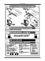
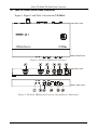
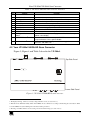
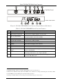
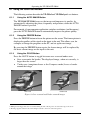
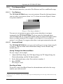
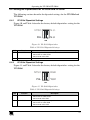
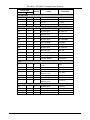
Kramer Electronics, Ltd.
USER MANUAL
Models:
VP-503xl, UXGA Scan Converter
VP-504xl, UXGA/HD Scan Converter
Contents
Contents
1
2
2.1
3
4
4.1
4.2
5
5.1
5.2
5.3
6
6.1
Introduction
Getting Started
Quick Start
Overview
Your VP-503xl/VP-504xl Scan Converter
Your VP-503xl UXGA Scan Converter
Your VP-504xl UXGA/HD Scan Converter
Connecting the VP-503xl/VP-504xl
Connecting your VP-503xl UXGA Scan Converter
Connecting your VP-504xl UXGA/HD Scan Converter
Controlling via RS-232 (for example, using a PC)
Operating the VP-503xl/VP-504xl
Using the Quick-Set Buttons
1
1
1
3
3
4
5
7
7
9
11
11
12
6.1.1
6.1.2
6.1.3
Using the AUTO IMAGE Button
Using the FREEZE Button
Using the OS/US Button
12
12
12
6.2
6.3
Adjusting the Display via the Menu Buttons
Using the Menu
13
13
6.3.1 The Advanced Menu
6.3.1.1 Test Patterns
6.3.1.2 Save and Recall
14
14
14
6.4
Setting the Dipswitches for VP-503xl and VP-504xl
15
6.4.1
6.4.2
VP-503xl Dipswitch Settings
VP-504xl Dipswitch Settings
15
15
7
8
Technical Specifications
VP-503xl / VP-504xl Communication Protocol
16
17
Figures
Figure 1: VP-503xl UXGA Scan Converter
Figure 2: VP-503xl UXGA Scan Converter (Top and Lower Side Panel)
Figure 3: VP-504xl UXGA/HD Scan Converter
Figure 4: VP-504xl UXGA/HD Scan Converter (Top and Lower Side Panel)
Figure 5: Connecting the VP-503xl
Figure 6: Connecting the VP-504xl
Figure 7: Connecting a PC without using a Null-modem Adapter
Figure 8: Over-scanned and Under-scanned images
Figure 9: Test Pattern Number 1
Figure 10: VP-503xl Dipswitches
Figure 11: VP-504xl Dipswitches
4
4
5
6
8
10
11
12
14
15
15
i
Contents
Tables
Table 1: VP-503xl UXGA Scan Converter Features
Table 2: VP-504xl UXGA/HD Scan Converter Features
Table 3: VP-503xl/VP-504xl Menu Items
Table 4: VP-503xl Dipswitch Settings
Table 5: VP-504xl Dipswitch Settings
Table 6: Technical Specifications of the VP-503xl/VP-504xl
Table 7: Set Commands
ii
5
6
13
15
15
16
17
KRAMER: SIMPLE CREATIVE TECHNOLOGY
Introduction
1
Introduction
Welcome to Kramer Electronics (since 1981): a world of unique, creative and
affordable solutions to the infinite range of problems that confront the video,
audio and presentation professional on a daily basis. In recent years, we have
redesigned and upgraded most of our line, making the best even better! Our
500-plus different models now appear in 8 Groups1, which are clearly defined
by function.
Congratulations on purchasing your Kramer VP-503xl UXGA Scan Converter
or VP-504xl UXGA/HD Scan Converter. This product is ideal for:
Multimedia, board rooms, and video conferencing
Any application where high quality conversion of graphical data signals to
video signals is required
Set-top box and HD conversion to SD video (VP-504xl)
The package includes the following items:
VP-503xl UXGA Scan Converter or VP-504xl UXGA/HD Scan Converter
Power adapter (12V DC Input)
Windows®-based Kramer control software2
This user manual3
2
Getting Started
We recommend that you:
Unpack the equipment carefully and save the original box and packaging
materials for possible future shipment
Review the contents of this user manual
Use Kramer high performance high resolution cables4
2.1 Quick Start
This quick start chart summarizes the basic setup and operation steps.
1 GROUP 1: Distribution Amplifiers; GROUP 2: Video and Audio Switchers, Matrix Switchers and Controllers; GROUP 3:
Video, Audio, VGA/XGA Processors; GROUP 4: Interfaces and Sync Processors; GROUP 5: Twisted Pair Interfaces;
GROUP 6: Accessories and Rack Adapters; GROUP 7: Scan Converters and Scalers; and GROUP 8: Cables and Connectors
2 Downloadable from our Web site at http://www.kramerelectronics.com
3 Download up-to-date Kramer user manuals from our Web site at http://www.kramerelectronics.com
4 The complete list of Kramer cables is on our Web site at http://www.kramerelectronics.com
1
Getting Started
2
KRAMER: SIMPLE CREATIVE TECHNOLOGY
Overview
3
Overview
The Kramer VP-503xl is a high quality scan converter for down-scaling
computer graphics (VGA up to UXGA) to PAL or NTSC video.
The Kramer VP-504xl is a high quality scan converter for down-scaling
computer graphics and HD to PAL or NTSC video. It supports VGA up to
UXGA, as well as the HD resolutions: 480p, 576p, 720p and 1080i. The input
color space (RGB or YUV) is selected via a dipswitch1.
The high quality VP-503xl/VP-504xl:
Has user-friendly front panel buttons for easy control of ProcAmp
functions, flicker-reduction, image optimization, one-touch freezing,
over-scanning and under-scanning
Can save and recall up to four setups, which include picture setup2, input
setup and output setup, zoom and advanced features
Outputs high quality composite video and s-Video (Y/C) simultaneously
Enables you to select the video standard (PAL or NTSC)
Can be controlled via the front panel buttons and via RS-232
Is fed from an external 12V DC source, making it suitable for field
operation
To achieve the best performance:
Connect only good quality connection cables, thus avoiding interference,
deterioration in signal quality due to poor matching, and elevated noiselevels (often associated with low quality cables)
Avoid interference from neighboring electrical appliances and position
your Kramer VP-503xl/VP-504xl away from moisture, excessive sunlight
and dust
4
Your VP-503xl/VP-504xl Scan Converter
This section describes the:
VP-503xl UXGA Scan Converter (see section 4.1)
VP-504xl UXGA/HD Scan Converter (see section 4.2)
1 See section 6.4
2 Brightness, contrast, saturation and flicker filter
3
Your VP-503xl/VP-504xl Scan Converter
4.1 Your VP-503xl UXGA Scan Converter
Figure 1, Figure 2 and Table 1 describe the VP-503xl:
Top Side Panel
Lower Side Panel
Figure 1: VP-503xl UXGA Scan Converter
Top Side Panel
Lower Side Panel
Figure 2: VP-503xl UXGA Scan Converter (Top and Lower Side Panel)
4
KRAMER: SIMPLE CREATIVE TECHNOLOGY
Your VP-503xl/VP-504xl Scan Converter
Table 1: VP-503xl UXGA Scan Converter Features
#
1
2
3
4
5
6
7
8
9
10
11
Feature
RS-232 DB 9F Port
INPUT HD15F Connector
PAL Dipswitch
CV OUT BNC Connector
Y/C OUT 4p Connector
12V DC
OS LED
FREEZE LED
MENU Button
ENTER / AUTO IMAGE
2
Button
- / FREEZE Button2
12
+ / OS/US Button2
Function
Connect to the PC or Remote Controller
Connect to the computer graphics source
Select the video standard (ON for PAL, OFF for NTSC)
Connect to the composite video acceptor
Connect to the s-Video acceptor
+12V DC connector for powering the unit
Lights when the image is over-scanned1
Lights when the FREEZE button is pressed
Press to enter the menu and adjust the Scan Converter features
Press ENTER to accept the settings; press AUTO IMAGE to acquire
optimal screen display
Press - to scroll down the menu; press FREEZE to freeze the video
image and features. Press again to disable
Press + to scroll up the menu; press OS/US to toggle between
1
3
over-scan and under-scan
4.2 Your VP-504xl UXGA/HD Scan Converter
Figure 3, Figure 4 and Table 2 describe the VP-504xl:
Top Side Panel
Lower Side Panel
Figure 3: VP-504xl UXGA/HD Scan Converter
1 The displayed image, when set correctly, is larger than the screen (see section 6.1.3)
2 This button has dual functionality. When in the MENU mode, it functions according to the labeling above the button. When
not in the MENU mode, the labeling below the button takes precedence
3 The image is smaller than the screen, leaving a border around the image (see section 6.1.3)
5
Your VP-503xl/VP-504xl Scan Converter
Top Side Panel
Lower Side Panel
Figure 4: VP-504xl UXGA/HD Scan Converter (Top and Lower Side Panel)
Table 2: VP-504xl UXGA/HD Scan Converter Features
#
1
Feature
RS-232 DB 9F Port
Function
Connect to the PC or Remote Controller
2
INPUT HD15F Connector
Connect to the computer graphics or HD source
PAL, YUV Dipswitches
Select the video standard (ON for PAL, OFF for NTSC) and the
color space (ON for YUV, OFF for RGB)
4
CV OUT BNC Connector
Connect to the composite video acceptor
5
Y/C OUT 4p Connector
Connect to the s-Video acceptor
6
12V DC
+12V DC connector for powering the unit
7
OS LED
Lights when the image is over-scanned1
8
FREEZE LED
Lights when the FREEZE button is pressed
9
MENU Button
Press to enter the menu and adjust the Scan Converter features
10
ENTER / AUTO IMAGE
Button2
Press ENTER to accept settings; press AUTO IMAGE to acquire
optimal screen display
11
- / FREEZE Button
Press - to scroll down the menu; press FREEZE to freeze the
video image and features. Press again to disable
12
+ / OS/US Button
Press + to scroll up the menu; press OS/US to toggle between
over-scan1 and under-scan3
3
1 The displayed image, when set correctly, is larger than the screen (see section 6.1.3)
2 This button has dual functionality. When in the MENU mode, it functions according to the labeling above the button. When
not in the MENU mode, the labeling below the button takes precedence
3 The image is smaller than the screen, leaving a border around the image (see section 6.1.3)
6
KRAMER: SIMPLE CREATIVE TECHNOLOGY
Connecting the VP-503xl/VP-504xl
5
Connecting the VP-503xl/VP-504xl
This section describes how to connect the:
VP-503xl UXGA Scan Converter (see section 5.1)
VP-504xl UXGA/HD Scan Converter (see section 5.2)
5.1 Connecting your VP-503xl UXGA Scan Converter
To connect your VP-503xl as the example in Figure 5 illustrates, do the
following1:
1.
Connect a computer graphics source to the HD15F INPUT connector.
2.
Connect the Y/C OUT 4p connector to the Y/C acceptor (for example, an
s-Video recorder) and/or the CV OUT BNC connector to the CV acceptor
(for example, a composite video recorder).
3.
If required, connect a PC or controller to the RS-232 port (see section 5.3).
4.
Set the dipswitches (see section 6.4.1).
5.
Connect the 12V DC power adapter to the power socket and connect the
adapter to the mains electricity (not shown in Figure 5).
Adjust the Scan Converter features if required (see section 6.3).
1 Switch OFF the power on each device before connecting it to your VP-503xl. After powering up your VP-503xl, switch on
the power on each device. The VP-504xl connection is similar to that of the VP-503xl
7
Connecting the VP-503xl/VP-504xl
RS-232
s-Video Recorder
Computer Graphics
Source
Composite Video Recorder
Figure 5: Connecting the VP-503xl
8
KRAMER: SIMPLE CREATIVE TECHNOLOGY
Connecting the VP-503xl/VP-504xl
5.2 Connecting your VP-504xl UXGA/HD Scan Converter
To connect your VP-504xl as the example in Figure 6 illustrates, do the
following1:
1.
Connect a high definition source2 to the HD15F INPUT connector (for
example, a set top box).
2.
Connect the Y/C OUT 4p connector to the Y/C acceptor (for example, an
s-Video recorder) and/or the CV OUT BNC connector to the CV acceptor
(for example, a composite video recorder).
3.
If required, connect a PC or controller to the RS-232 port (see section 5.3).
4.
Set the dipswitches (see section 6.4.2).
5.
Connect the 12V DC power adapter to the power socket and connect the
adapter to the mains electricity (not shown in Figure 6).
Adjust the Scan Converter features if required (see section 6.3).
1 Switch OFF the power on each device before connecting it to your VP-504xl. After powering up your VP-504xl, switch on
the power on each device
2 To connect a high definition source, use a breakout cable such as the Kramer C-GM/3RVF. If you have a VGA to a 5BNC
cable, use the RGB wires only. For direct wiring, see the table in Figure 6
9
Connecting the VP-503xl/VP-504xl
INPUT Connector PINOUT
PIN #
1
2
3
Signal
Pr
Y
Pb
RS-232
s-Video Recorder
Set Top Box
Source
Composite Video Recorder
Figure 6: Connecting the VP-504xl
10
KRAMER: SIMPLE CREATIVE TECHNOLOGY
Operating the VP-503xl/VP-504xl
5.3 Controlling via RS-232 (for example, using a PC)
To connect a PC to the VP-503xl/VP-504xl unit, using the Null-modem
adapter provided with the machine (recommended):
Connect the RS-232 DB9 rear panel port on the VP-503xl/VP-504xl unit
to the Null-modem adapter and connect the Null-modem adapter with a
9-wire flat cable to the RS-232 DB9 port on your PC
To connect a PC to the VP-503xl/VP-504xl unit, without using a Null-modem
adapter:
Connect the RS-232 DB9 port on your PC to the RS-232 DB9 rear panel
port on the Master VP-503xl/VP-504xl unit, as Figure 7 illustrates
PIN 5 Connected to PIN 5 (Ground)
PIN 3 Connected to PIN 2
PIN 2 Connected to PIN 3
Female DB9 (From PC)
Male DB9
PIN 4 Connected to PIN 6
PINS 8, 7, 1 Connected together
If a Shielded cable is used, connect the shield to PIN 5
Figure 7: Connecting a PC without using a Null-modem Adapter
6
Operating the VP-503xl/VP-504xl
You can operate your VP-503xl/VP-504xl via the front panel buttons, which
are dual-purpose buttons1 that function as:
Quick-set buttons: AUTO IMAGE, FREEZE and OS/US, or
Menu buttons: MENU, ENTER, – and +
This section describes how to:
Use the Quick set buttons (see section 6.1)
Use the set of menu buttons (see section 6.2)
Use the Menu screen (see section 6.3)
Set the dipswitches (see section 6.4)
1 Except for the MENU button
11
Operating the VP-503xl/VP-504xl
6.1 Using the Quick-Set Buttons
The following sections describe the VP-503xl and VP-504xl quick set-buttons.
6.1.1
Using the AUTO IMAGE Button
The VP-503xl/VP-504xl assesses the image and improves its quality, by
automatically adjusting the phase, frequency and position, when the AUTO
IMAGE button is pressed.
For example, if your computer application switches resolutions (and frequency),
press the AUTO IMAGE button to automatically improve the picture quality.
6.1.2
Using the FREEZE Button
Press the FREEZE button to freeze the picture on the screen. The frozen picture is
displayed regardless of the signal on the input to the unit. This allows you, for
example, to change the programs on the PC, and set up the next image.
By pressing the FREEZE button again, the frozen image will be replaced by
the most current image on the input to the unit.
6.1.3
Using the OS/US Button
Press the OS/US button to toggle between over-scan and under-scan:
Over-scan omits the border. The displayed image, when set correctly, is
larger than the screen1
Under-scan (sometimes know as the Compress mode) leaves a border
around the image2
Over-scan
Under-scan
Figure 8: Over-scanned and Under-scanned images
1 Making the data bigger and easier to read but running the risk of having some of it run off the edge of the screen
2 The image appears reduced in size with a margin around it so that none of the data gets lost
12
KRAMER: SIMPLE CREATIVE TECHNOLOGY
Operating the VP-503xl/VP-504xl
6.2 Adjusting the Display via the Menu Buttons
The set of menu buttons (MENU, ENTER, and +) let you adjust the screen
settings. Use the menu buttons as follows:
Press the MENU1 button to display the menu on the screen
Press the MENU button again each time you want to return to the
previous menu level or exit the menu
Press the + or - buttons to move up or down the menu respectively
Press ENTER to accept changes
Before exiting the menu, you can save settings2
6.3 Using the Menu
Using the main menu, you can adjust the screen display3. After pressing the
MENU button4, the main Menu5 appears on the screen. Use the menu buttons
to scroll through the menu and make the required adjustments. Table 3
defines the menu items.
Table 3: VP-503xl/VP-504xl Menu Items
Menu Items
Picture Setup
Function
Set the Contrast, Brightness, Sharpness and Saturation levels;
Set the Flicker Filter for flicker reduction6
TV Output Setup
Set the H Center, H Width, V Center and V Height levels
VGA Input Setup
Zoom
Set the VGA Left, VGA Width, VGA Top and VGA Bottom levels
Set the zoom to ON to zoom the image; when the zoom is selected, pan the H and V
position
Select from seven different Test Patterns (for example, see Figure 9);
Select a test pattern to appear when no input is connected; and
Save up to 4 setups2 and recall them
Advanced
Information
Verifies the V Total Line, the H Timing, the V Timing, and the software version
1 Pressing the MENU button disables the quick-set buttons (AUTO IMAGE, FREEZE and OS/US)
2 See section 6.3.1.2
3 Screen adjustments apply to both CV and Y/C displays
4 Quick set-buttons are disabled
5 The menu times-out after 20 seconds of inactivity
6 The flicker filter essentially blends the value of vertically adjacent pixels to decrease the differences in adjacent odd/even
lines. This dramatically reduces the noticeable image flicker, but it also reduces the level of the vertical detail
13
Operating the VP-503xl/VP-504xl
6.3.1
The Advanced Menu
The Advanced menu lets you select Test Patterns and Save and Recall setups.
6.3.1.1
Test Patterns
The VP-503xl/VP504xl stores seven test patterns. From the Advanced menu,
you can select a test pattern (from 1 to 7) to show on screen. Figure 9 shows
test pattern number 1.
Figure 9: Test Pattern Number 1
You can set a test pattern to appear on the screen when there is no input
connected to the VP-503xl/VP504xl. To do so, enter the Advanced menu,
select No Input and set a test pattern number. This test pattern will appear when
there is no input connected. For example, set No Input to 1 if you want test
pattern 1 (as in Figure 9) to appear when there is no input connected to the unit.
6.3.1.2
Save and Recall
The VP-503xl/VP-504xl lets you save and recall up to 4 setups (from setup 0
to setup 3). The Save mode stores all the menu settings1 in the selected setup
memory (0 to 3).
Saving Through the Advanced Menu
To save setup 1, for example:
1.
Adjust the Picture Setup, the VGA Input Setup, the TV Output Setup, the
Zoom and panning, and the No Input number.
2.
In the Advanced menu, select Save and set to number 1.
3.
Press ENTER.
The setup is saved.
Recalling a Setup
To recall a setup select Recall from the advanced menu and select the setup
number you want to recall.
1 The Save mode saves the Picture setup, the TV Output setup, the VGA Input Setup, the Zoom setup, and the advanced setup
(test patterns)
14
KRAMER: SIMPLE CREATIVE TECHNOLOGY
Operating the VP-503xl/VP-504xl
6.4 Setting the Dipswitches for VP-503xl and VP-504xl
The following sections describe the dipswitch settings for the VP-503xl and
VP-504xl.
6.4.1
VP-503xl Dipswitch Settings
Figure 10 and Table 4 describe the factory default dipswitches setting for the
VP-503xl:
NTSC
PAL
N.U.
1 2
ON
N.U.
Figure 10: VP-503xl Dipswitches
Table 4: VP-503xl Dipswitch Settings
DIP
1
Function
PAL/NTSC
Description
Determines the video standard to be used:
Set to OFF to select NTSC
Set to ON to select PAL
2
N.U
Not Used
6.4.2
VP-504xl Dipswitch Settings
Figure 11 and Table 5 describe the factory default dipswitches setting for the
VP-504xl:
NTSC
PAL
RGB
1 2
ON
YUV
Figure 11: VP-504xl Dipswitches
Table 5: VP-504xl Dipswitch Settings
DIP
1
Function
PAL/NTSC
Description
Determines the video standard to be used:
Set to OFF to select NTSC
Set to ON to select PAL
2
YUV/RGB
Determines the input color space to be used:
Set to OFF to select RGB
Set to ON to select YUV
15
Technical Specifications
7
Technical Specifications
Table 6 includes the technical specifications.
1
Table 6: Technical Specifications of the VP-503xl/VP-504xl
INPUTS:
VP-503xl: 1 x VGA/ UXGA on an HD15F connector
VP-504xl: 1 x VGA/ UXGA, analog component HD on an HD15F connector
OUTPUTS:
1 composite video 1Vpp/75 on a BNC connector
1 Y/C (s-Video) 1Vpp / 75 ohms (Y), 0.3Vpp / 75 ohms (C) on a 4p
connector
1Vpp
VP-503xl: VGA up to UXGA
VP-504xl: VGA up to UXGA; 480p, 576p, 720p, 1080i (for 1080i, does not
support 50Hz)
Front panel, RS-232 and OSD: ProcAmp video controls, Freeze,
Underscan / Overscan, Auto-image, 8 color bars
12VDC, 310mA
18.8cm x 11.4cm x 2.4cm (7.41" x 4. 5" x 0.95", W, D, H)
0.4 kg. (0.88 lbs.) approx.
Power supply, mounting bracket
VGA to 3RCA breakout cable C-GM/3RVF
MAX. OUTPUT LEVEL:
INPUT RESOLUTIONS:
CONTROLS:
POWER SOURCE:
DIMENSIONS:
WEIGHT:
ACCESSORIES:
OPTIONS:
1 Specifications are subject to change without notice
16
KRAMER: SIMPLE CREATIVE TECHNOLOGY
VP-503xl / VP-504xl Communication Protocol
8
VP-503xl / VP-504xl Communication Protocol
Set Command: Y Control_Type Function Param CR
Reply: Z Control_Type Function Param CRDoneCR
Get Command: Y Control_Type Function CR
Reply : Z Control_Type Function Param CR
Example:
1.
"Y 0 7 31 CR" -> set Contrast value as 31
"Z 0 7 31 CR"
2.
"Y 1 7 CR" -> get current Contrast value
"Z 1 7 31 CR" -> current Contrast value is 31
: ASCII Code 0x20
CR : Ascii Code 0xD or 0xA
Table 7 defines the Set Commands:
Table 7: Set Commands
Control Type
Set
Get
Function
Param
Description
Keypad
0
N/A
0
N/A
Menu
0
N/A
1
N/A
Enter
0
0
N/A
N/A
2
3
N/A
N/A
+
0
N/A
4
N/A
Auto Image
Freeze
0
1
5
0: Off
1: On
0
1
6
0: OS
1: US
OS/US
0
1
7
-32~31
Contrast
0
1
8
Brightness
0
1
9
0
1
10
-32~31
0: Off
1: On
0~8
0
1
11
-32~31
Saturation
Picture Setup
Sharpness
Flicker Filter
17
VP-503xl / VP-504xl Communication Protocol
Control Type
Set
Get
Function
Param
Description
TV Output Setup
0
1
12
-16~16
H Center
0
1
13
-16~16
H Width
0
1
14
-10~10
V Center
0
1
15
-10~10
V Height
VGA Input Setup
N/A
1
16
By input signal
Max VGA Left
N/A
1
17
By input signal
Min VGA Left
VGA Left
0
1
18
Max VGA Left ~
Min VGA Left
N/A
1
19
By input signal
Max VGA Width
N/A
1
20
By input signal
Min VGA Width
VGA Width
0
1
21
Max VGA Width ~
Min VGA Width
N/A
1
22
By input signal
Max VGA Top
N/A
1
23
By input signal
Min VGA Top
VGA Top
0
1
24
Max VGA Top ~
Min VGA Top
N/A
1
25
By input signal
Max VGA Bottom
N/A
1
26
By input signal
Min VGA Bottom
1
27
Max VGA Bottom ~
Min VGA Bottom
VGA Bottom
0
1
28
0: Off
1: On
Zoom
N/A
1
29
By input/output signal
Max Pan H-Pos
N/A
1
30
By input/output signal
Min Pan H-Pos
Pan H-Pos
Max Pan V-Pos
0
Zoom
0
1
31
Max Pan H-Pos ~
Min Pan H-Pos
N/A
1
32
By input/output signal
N/A
1
33
0
1
34
By input/output signal
Max Pan V-Pos ~
Min Pan V-Pos
N/A
1
35
By input signal
V total Line
N/A
1
36
By input signal
H Timing
N/A
1
37
By input signal
V Timing
N/A
1
38
Min Pan H-Pos
Pan V-Pos
Information
18
Version
KRAMER: SIMPLE CREATIVE TECHNOLOGY
LIMITED WARRANTY
Kramer Electronics (hereafter Kramer) warrants this product free from defects in material and workmanship under the
following terms.
HOW LONG IS THE WARRANTY
Labor and parts are warranted for seven years from the date of the first customer purchase.
WHO IS PROTECTED?
Only the first purchase customer may enforce this warranty.
WHAT IS COVERED AND WHAT IS NOT COVERED
Except as below, this warranty covers all defects in material or workmanship in this product. The following are not covered
by the warranty:
1.
2.
3.
Any product which is not distributed by Kramer, or which is not purchased from an authorized Kramer dealer. If you are
uncertain as to whether a dealer is authorized, please contact Kramer at one of the agents listed in the Web site
www.kramerelectronics.com.
Any product, on which the serial number has been defaced, modified or removed.
Damage, deterioration or malfunction resulting from:
i)
Accident, misuse, abuse, neglect, fire, water, lightning or other acts of nature
ii)
Product modification, or failure to follow instructions supplied with the product
iii)
Repair or attempted repair by anyone not authorized by Kramer
iv)
Any shipment of the product (claims must be presented to the carrier)
v)
Removal or installation of the product
vi)
Any other cause, which does not relate to a product defect
vii)
Cartons, equipment enclosures, cables or accessories used in conjunction with the product
WHAT WE WILL PAY FOR AND WHAT WE WILL NOT PAY FOR
We will pay labor and material expenses for covered items. We will not pay for the following:
1.
2.
3.
Removal or installations charges.
Costs of initial technical adjustments (set-up), including adjustment of user controls or programming. These costs are the
responsibility of the Kramer dealer from whom the product was purchased.
Shipping charges.
HOW YOU CAN GET WARRANTY SERVICE
1.
2.
3.
To obtain service on you product, you must take or ship it prepaid to any authorized Kramer service center.
Whenever warranty service is required, the original dated invoice (or a copy) must be presented as proof of warranty coverage,
and should be included in any shipment of the product. Please also include in any mailing a contact name, company, address, and
a description of the problem(s).
For the name of the nearest Kramer authorized service center, consult your authorized dealer.
LIMITATION OF IMPLIED WARRANTIES
All implied warranties, including warranties of merchantability and fitness for a particular purpose, are limited in duration to
the length of this warranty.
EXCLUSION OF DAMAGES
The liability of Kramer for any effective products is limited to the repair or replacement of the product at our option. Kramer
shall not be liable for:
1.
2.
Damage to other property caused by defects in this product, damages based upon inconvenience, loss of use of the product, loss
of time, commercial loss; or:
Any other damages, whether incidental, consequential or otherwise. Some countries may not allow limitations on how long an
implied warranty lasts and/or do not allow the exclusion or limitation of incidental or consequential damages, so the above
limitations and exclusions may not apply to you.
This warranty gives you specific legal rights, and you may also have other rights, which vary from place to place.
NOTE: All products returned to Kramer for service must have prior approval. This may be obtained from your dealer.
This equipment has been tested to determine compliance with the requirements of:
EN-50081:
"Electromagnetic compatibility (EMC);
generic emission standard.
Part 1: Residential, commercial and light industry"
EN-50082:
"Electromagnetic compatibility (EMC) generic immunity standard.
Part 1: Residential, commercial and light industry environment".
CFR-47:
FCC Rules and Regulations:
Part 15: “Radio frequency devices
Subpart B – Unintentional radiators”
CAUTION!
Servicing the machines can only be done by an authorized Kramer technician. Any user who makes changes or modifications to
the unit without the expressed approval of the manufacturer will void user authority to operate the equipment.
Use the supplied DC power supply to feed power to the machine.
Please use recommended interconnection cables to connect the machine to other components.
19
For the latest information on our products and a list of Kramer
distributors, visit our Web site: www.kramerelectronics.com,
where updates to this user manual may be found.
We welcome your questions, comments and feedback.
Safety Warning:
Disconnect the unit from the power supply before
opening/servicing.
Caution
Kramer Electronics, Ltd.
Web site: www.kramerelectronics.com
E-mail: [email protected]
P/N: 2900-000198 REV 1