1
S200 High Performance Compact
Brushless Servo Drives
SynqNet and Base Units
Solutions By
D A N A H ER
M O TI O N
Reference Manual
M-SM-200-01
Revision A
®
C
US
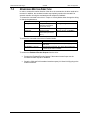
Revision History
Date
Issue
Description
05/2004
03/2006
Initial Release
Addition of SynqNet information
A
© 2006, Danaher Motion - All rights reserved.
Printed in the United States of America.
NOTICE:
Danaher Motion® is a registered trademark of the Danaher Corporation. Danaher Motion makes every
attempt to ensure accuracy and reliability of the specifications in this publication. Specifications are
subject to change without notice. Danaher Motion provides this information "AS IS" and disclaims all
warranties, express or implied, including, but not limited to, implied warranties of merchantability and
fitness for a particular purpose. It is the responsibility of the product user to determine the suitability of
this product for a specific application.
Safety Symbols
WARNING
Warnings - alert users to potential physical danger or harm.
Failure to follow warning notices could result in personal
injury or death.
CAUTION
Cautions - direct attention to general precautions. Personal
injury and/or equipment damage could result if precautions
are ignored.
NOTE
Notes - highlight information critical to your understanding
or use of the product.
Danaher Motion Kollmorgen
03/2006
Table of Contents
Table of Contents
1
2
3
S200 Series Drives ...................................................................................................................1
1.1
Model Number ...............................................................................................................2
1.2
Drive Model Numbers and Descriptions ........................................................................2
Before You Begin .....................................................................................................................4
2.1
Safety ............................................................................................................................4
2.2
Unpacking and Inspecting .............................................................................................4
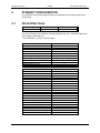
Specifications ...........................................................................................................................5
3.1
Drive Family Power........................................................................................................5
3.2
AC Input Drives - Control and Power.............................................................................6
3.3
3.4
3.5
3.2.1
AC Control Power Supply..................................................................................6
3.2.2
AC Motor Power Supply ....................................................................................7
3.2.3
AC Bus Voltage and Faults ...............................................................................7
3.2.4
AC Inrush Current & Fusing ..............................................................................7
3.2.5
AC Control Inrush Current & Fusing ..................................................................7
3.2.6
AC Power On Delay ..........................................................................................7
DC Input Drives - Control and Power.............................................................................8
3.3.1
DC Control Power Supply..................................................................................8
3.3.2
DC Bus Voltage and Faults ...............................................................................8
3.3.3
DC Power On Delay ..........................................................................................8
Motor Current Control ....................................................................................................8
3.4.1
Current Loop Bandwidth....................................................................................8
3.4.2
Offset Current....................................................................................................9
Velocity Loop .................................................................................................................9
3.5.1
3.6
4
Velocity Loop Compensation.............................................................................9
I/O..................................................................................................................................9
3.6.1
Analog Command..............................................................................................9
3.6.2
Analog Output (DacMon).................................................................................10
3.6.3
HSINP – Step/PWM Command.......................................................................10
3.6.4
SINP - Direction Command .............................................................................10
3.6.5
Quadrature Input .............................................................................................10
3.6.6
General Purpose Inputs ..................................................................................10
3.6.7
General Purpose Outputs................................................................................11
3.6.8
Quadrature Outputs.........................................................................................11
3.7
Mechanical ..................................................................................................................11
3.8
Environmental..............................................................................................................11
3.9
Smart Feedback Device (SFD) ....................................................................................12
3.9.1
Position Signal.................................................................................................12
3.9.2
Velocity Signal.................................................................................................12
3.9.3
Emulated Encoder Output Signals ..................................................................13
3.9.4
General SFD Specifications ............................................................................13
Quick Start Guides .................................................................................................................14
4.1
S200 Base Unit Drive ..................................................................................................14
4.1.1
S200 Tools Software Installation .....................................................................14
4.1.2
Hardware Setup ..............................................................................................14
S200 Reference Manual
M-SM-200-01
i
Table of Contents
4.2
5
6
03/2006
Danaher Motion Kollmorgen
4.1.3
S200 Tools Communications Wizard ..............................................................15
4.1.4
Motor Feedback Configuration ........................................................................17
4.1.5
Save Options...................................................................................................17
S200 SynqNet Drive ....................................................................................................17
4.2.1
MDK and SynqNet Controller Installation ........................................................17
4.2.2
S200 Tools Software Installation .....................................................................18
4.2.3
Hardware Setup ..............................................................................................18
4.2.4
S200 Tools Communication Wizard ................................................................19
4.2.5
SynqNet Configuration ....................................................................................21
4.2.6
Motor Feedback Configuration ........................................................................21
4.2.7
Save Options...................................................................................................22
Mounting the Drive .................................................................................................................23
5.1
Mounting Dimensions ..................................................................................................23
5.2
Mechanical Outline Drawings ......................................................................................25
5.2.1
Base AC Drive.................................................................................................25
5.2.2
Base DC Drive.................................................................................................26
5.2.3
SynqNet AC Drive ...........................................................................................27
5.2.4
SynqNet DC Drive ...........................................................................................28
Wiring the Drive ......................................................................................................................29
6.1
AC Input Drive Wiring ..................................................................................................29
6.2
J1 – AC Input Drive Power ..........................................................................................30
6.3
DC Input Drive Wiring ..................................................................................................33
6.4
J1 – DC Input Drive Power ..........................................................................................34
6.4.1
DC Power Supply Requirements.....................................................................35
6.4.2
Bus Voltage .....................................................................................................36
6.4.3
Control Voltage................................................................................................36
6.4.4
Grounding........................................................................................................37
6.4.5
Bus Capacitance .............................................................................................37
6.4.6
Bus Switching and Fusing ...............................................................................37
6.5
J2 – Motor Power Connector .......................................................................................38
6.6
J3 – Feedback Connector............................................................................................39
6.7
J4 – Command I/O Connector .....................................................................................40
6.8
6.7.1
General Purpose Inputs ..................................................................................40
6.7.2
General Purpose Outputs................................................................................44
6.7.3
High Speed Input.............................................................................................46
6.7.4
SFD BAT+ .......................................................................................................47
6.7.5
DAC Monitors ..................................................................................................48
6.7.6
Encoder Outputs/Inputs...................................................................................48
6.7.7
Analog Command Input...................................................................................50
J5 – Serial Port Connector...........................................................................................51
6.8.2
Serial Interface Specification ...........................................................................52
6.8.3
RS-232 Wiring .................................................................................................52
6.9
SynqNet Option Card Wiring .......................................................................................53
6.10
J11 – SynqNet IN Port Connector................................................................................54
6.10.1 SynqNet LEDs.................................................................................................54
6.11
J12 – SynqNet OUT Port Connector............................................................................55
6.11.1 SynqNet LEDs.................................................................................................55
ii
M-SM-200-01
S200 Reference Manual
Danaher Motion Kollmorgen
03/2006
6.12
J13 – Discrete I/O Connector ......................................................................................56
6.13
J14 – AUX FB Connector ............................................................................................57
Table of Contents
6.13.1 Auxiliary Feedback Device Port.......................................................................57
7
Basic Configuration ...............................................................................................................58
7.1
S2 - DIP Setup Switch .....................................................................................58
7.1.2
S1 - Rotary Setup Switch ................................................................................59
7.1.3
S11, S12 - Rotary SynqNet ID Switches .........................................................60
Configuring for Brush Motors.......................................................................................62
7.3
Configuring Current Mode with 6-Step (Hall) Feedback ..............................................63
7.5
9
7.1.1
7.2
7.4
8
Switch Settings ............................................................................................................58
7.3.1
Torque Block with 6-Step Feedback Wiring.....................................................63
7.3.2
Setting Drive Parameters for 6-Step Operation ...............................................63
Configuring with SFD Feedback ..................................................................................65
7.4.1
Motor Parameters............................................................................................65
7.4.2
Torque/Current Mode ......................................................................................66
7.4.3
Velocity Mode..................................................................................................67
7.4.4
Position Mode..................................................................................................68
Reversing Motion Direction..........................................................................................69
Advanced Configuration ........................................................................................................70
8.1
Control Block Diagram.................................................................................................71
8.2
Position Control Diagram.............................................................................................72
8.3
Parameters and Variables ...........................................................................................73
8.3.1
Parameter and Variable Storage .....................................................................73
8.3.2
Model Dependent Scale Factors .....................................................................74
8.3.3
Read/Write NV Parameters .............................................................................75
8.3.4
Status And Control Variables ..........................................................................83
SynqNet Configuration ..........................................................................................................88
9.1
Drive FPGA Table........................................................................................................88
9.2
Drive Monitor ...............................................................................................................89
9.3
10
9.2.1
Drive Monitor Table .........................................................................................89
9.2.2
Monitoring Real-time Data from Drive .............................................................89
Accessing Drive Parameters over SynqNet.................................................................90
9.3.1
Introduction......................................................................................................90
9.3.2
Memory Operations on Drive Parameters .......................................................90
9.3.3
Accessing Individual Parameters ....................................................................91
9.3.4
Accessing an Entire Parameter Set.................................................................91
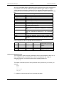
Accessories, Connector Kits, and Cables.....................................................................95
10.1
Accessories .................................................................................................................95
10.2
Connector Kits .............................................................................................................95
10.3
Cables .........................................................................................................................96
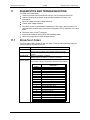
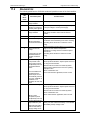
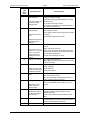
11
Diagnostics and Troubleshooting .................................................................................97
11.1
Drive Fault Codes ........................................................................................................97
11.2
Diagnostics ..................................................................................................................99
11.2.1 Fault Generation............................................................................................102
S200 Reference Manual
M-SM-200-01
iii
Table of Contents
03/2006
Danaher Motion Kollmorgen
Appendix A - Power Supply Design ...........................................................................................103
A.1
A.2
Design .......................................................................................................................103
A.1.1
Single Power Supply Operation.....................................................................103
A.1.2
Main Supply Output Capacitance (J1-3 to J1-2)............................................105
Two Power Supply Operation ....................................................................................108
A.2.1
Control Supply (J1-1 to J1-2).........................................................................108
A.3
Multi-Axis Considerations ..........................................................................................108
A.4
Bus Energy & Power Numerical Examples................................................................109
A.4.1
Min. External Bus Capacitance .....................................................................109
A.4.2
Energy from Acceleration Time .....................................................................109
A.4.3
Capacitor Energy Absorb/Deliver ..................................................................109
A.4.4
Bus DC Input Power ......................................................................................109
Appendix B - Cables....................................................................................................................111
B.1
Long Cables ..............................................................................................................111
B.2
Custom Composite Cables ........................................................................................111
Appendix C - Voltage Sag Standard...........................................................................................114
Appendix D - Using a Voltage Doubler Mode Drive ..................................................................115
D.1
S2xx50 AC Line Voltage Doubling Drive Power Specifications ................................116
Appendix E - Regulatory Information ........................................................................................117
E.1
Conformance Requirements ......................................................................................117
E.2
CE Approval ..............................................................................................................117
E.2
CE EMC Compliance.................................................................................................117
E.2.1. CE Test Setup ...............................................................................................118
iv
E.2.2
CE Test Setup ...............................................................................................118
E.2.3
Declaration of Conformity ..............................................................................119
E.3
Installation and Commissioning .................................................................................121
E.4
Safety requirements...................................................................................................121
E.5
European Compliance ...............................................................................................121
E.6
Low Voltage Directive and EN50178 .........................................................................122
E.7
UL and cUL Conformance .........................................................................................123
E.8
Additional Safety Precautions ....................................................................................124
E.9
EMC Compliance with EN61800-3 ............................................................................125
E.10
AC Mains Conducted Emissions................................................................................125
E.11
Regen Resistor ..........................................................................................................126
E.12
Additional EMC Information Sources .........................................................................126
E.13
Customer Support......................................................................................................126
M-SM-200-01
S200 Reference Manual
Danaher Motion Kollmorgen
1
03/2006
S200 Series Drives
S200 SERIES DRIVES
Industry-Leading Performance In A Small Package
Danaher Motion’s Kollmorgen S200 brushless servo drives puts high performance servo
technology into lower power applications than was previously possible without having to
compromise on reliability or package size. Coupling an S200 drive with Danaher Motion's
AKM servomotor provides a complete servo control solution designed to excel in
applications such as semiconductor fabrication, electronic assembly, packaging, medical,
and woodworking equipment among others. Danaher Motion's S200 servo drives are the
first all-digital industrial drives with a velocity loop bandwidth up to 800 Hz, offering
unmatched system throughput and simplified tuning. High resolution (24 bit) feedback and
high performance 3-5 kHz current loop bandwidth provide smooth motion and rapid start
and stop action to optimize machine performance. Smart feedback and industry leading
high bandwidth deliver fast and accurate "plug and play" commissioning by eliminating the
need for servo loop tuning in most applications.
Base S200 servo drives come standard with torque or velocity control, as well as with
factory options that support SynqNet or add pre-settable Indexing with CANopen
communications. The factory option cards also add interfaces to additional motor feedback
devices such as Comcoder, 1 Vp-p Sin-Cos, and EnDat 2.1. The drives operate with AC
(120/240 VAC) or DC (20-90 VDC) power sources and have current ratings from 1.5 ARMS
continuous to 18 ARMS peak. Their compact footprint ranges from 1.1 in (28.7 mm) wide
and 6.0 in (152.4 mm) tall to 2.44 in (62 mm) wide and 6.9 in (175 mm) tall with depths
ranging from 3.9 in (100.8 mm) to 5.2 in (131.6 mm), allow them to fit into tight spaces.
They are UL 508C recognized, CE marked, and conform to EN50178 and EN61800-3
standards.
Separate "Keep Alive" control power input allows communications and diagnostics to
continue during emergency stop conditions with no power to the motor. It also allows rapid
recovery from emergency stops. Optically isolated inputs and outputs, positive locking
connectors, and full fault protection promise long machine life and immunity to accidental
damage. The single motor power or feedback cable option simplifies connectivity. All
connectors and LED status indicators are easily accessible from the front of the drive.
S200 Reference Manual
M-SM-200-01
1
S200 Series Drives
1.1
03/2006
Danaher Motion Kollmorgen
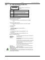
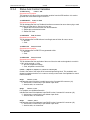
MODEL NUMBER
S2 03 3 0 VT S - 002
Family
S2 - 200 Servo Family
Customization - omit for standard drives
000 - 019 Reserved for factory use
020 - 999 Reserved for customers
Feedback Support
S - SFD/Halls - Base Unit
SFD/Comcoder - CAN Option card
Smart Feedback Device (SFD) - SynqNet Option Card
Sine encoder - SynqNet Option Card
EnDat 2.1 - SynqNet Option Card
Current Rating
02 - 1.5 ARMS continuous,
4.5 ARMS peak
03 - 3 ARMS continuous,
9 ARMS peak
06 - 6 ARMS continuous,
18 ARMS peak
Voltage
3 - 20 - 90 VDC
5 - 120 VAC doubler/240 VAC 1 ph
6 - 120/240 VAC
1.2
Functionality
VT - Velocity/Torque modes
CN - Position Node w/ CANOpen Interface
SD - SynqNet option card w/ micro-D connectors
SR - SynqNet option card w/ standard RJ connectors
Electrical Option
0 - No Electrical Option
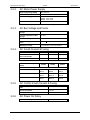
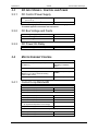
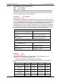
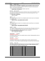
DRIVE MODEL NUMBERS AND DESCRIPTIONS
Here is a list of the various S200 Series Drives.
•
CNS - CAN/Indexer option card
•
SRS - SynqNet option card with RJ-45 connectors
•
SDS - SynqNet option card with Micro-D connectors
•
VTS – Analog Velocity/Torque Base Drive
AC Drive
S20260-VTS
S20360-VTS
S20250-VTS
S20350-VTS
S20260-SRS
S20360-SRS
S20250-SRS
S20260-SDS
S20360-SDS
S20250-SDS
S20350-SDS
2
Description
S200 120/240 VAC, 1/3-phase, 1.5/4.5 ARMS Base Unit
S200 120/240 VAC, 1/3-phase, 3/9 ARMS Base Unit
S200 120 VAC, doubler/240 VAC 1 ph 1.4/4.5 ARMS Base Unit
S200 120 VAC, doubler/240 VAC 1 ph 3.9 ARMS Base Unit
S200 120/240 VAC 1/3-phase 1.5/4.5 ARMS SynqNet with RJ-45
connectors
S200 120/240 VAC 1/3 phase 3/9 ARMS SynqNet with RJ-45
connectors
S200 120 VAC doubler/240 VAC 1 ph 1.4/4.5 ARMS SynqNet with
RJ-45 connectors
S200 120/240 VAC 1/3 phase 1.5/4.5 ARMS SynqNet with Micro-D
connectors
S200 120/240 VAC 1/3 phase 3/9 ARMS SynqNet with Micro-D
connectors
S200 120 VAC doubler/240 VAC 1 ph 1.4/4.5 ARMS SynqNet with
Micro-D connectors
S200 120 VAC doubler/240 VAC 1 ph 3/9 ARMS SynqNet with
Micro-D connectors
M-SM-200-01
S200 Reference Manual
Danaher Motion Kollmorgen
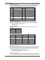
DC Drive
S20330-VTS
S20630-VTS
S20330-CNS
S20630-CNS
S20330-SRS
S20630-SRS
S20330-SDS
S20630-SDS
S200 Reference Manual
03/2006
S200 Series Drives
Description
S200 90 VDC, 3/9 ARMS Base Unit
S200 90 VDC, 6/18 ARMS Base Unit
S200 90 VDC, 3/9 ARMS Base Unit, CAN/Indexer option card
S200 90 VDC, 6/18 ARMS Base Unit, CAN/Indexer option card
S200 90 VDC, 3/9 ARMS Base Unit, SynqNet option card with RJ45 connectors
S200 90 VDC, 6/18 ARMS Base Unit, SynqNet option card with
RJ-45 connectors
S200 90 VDC 3/9 ARMS SynqNet with Micro-D connectors
S200 90 VDC 6/18 ARMS SynqNet with Micro-D connectors
M-SM-200-01
3
Before You Begin
03/2006
2
BEFORE YOU BEGIN
2.1
SAFETY
WARNING
Danaher Motion Kollmorgen
READ these instructions before connecting power. Damage can
result from MISWIRING at the power terminals.
DANGEROUS voltages are present on power input and motor output
terminals.
Only qualified personnel are permitted to transport, assemble, commission, and maintain
this equipment. Properly qualified personnel are persons who are familiar with the
transport, assembly, installation, commissioning and operation of motors, and who have
the appropriate qualifications for their jobs.
Read all available documentation before assembling and using. Incorrect handling of
products described in this manual can result in injury and damage to people and/or
machinery. Strictly adhere to the technical information regarding installation requirements.
Keep all covers and cabinet doors shut during operation.
Be aware that during operation, the product has electrically charged components and
hot surfaces. Control and power cables can carry a high voltage, even when the
motor is not rotating.
Never disconnect or connect the product while the power source is energized.
After removing the power source from the equipment, wait at least 5 minutes before
touching or disconnecting sections of the equipment that normally carry electrical
charges (e.g., capacitors, contacts, screw connections). To be safe, measure the
electrical contact points to each other and to electrical safety earth with a meter
before touching the equipment.
2.2
UNPACKING AND INSPECTING
Open the box and remove all the contents. Check to ensure there is no visible damage to
any of the equipment.
CAUTION
CAUTION
NOTE
4
Use proper procedures when handling electronic
components to avoid damage to equipment.
Remove all packing material and equipment from the
shipping container. Be aware that some connector kits and
other equipment pieces may be quite small and can be
accidentally discarded. Do not dispose of shipping
materials until the packing list has been checked.
Upon receipt of the equipment, inspect components to
ensure that no damage has occurred in shipment. If damage
is detected, notify the carrier immediately. Check all
shipping material for connector kits, documentation,
diskettes, CD-ROM, or other small pieces of equipment.
M-SM-200-01
S200 Reference Manual
Danaher Motion Kollmorgen
3
Specifications
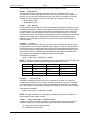
SPECIFICATIONS
NOTE
3.1
03/2006
Unless otherwise specified, the specifications are worse-case limits
and apply over the specified operating ambient temperature and
over the specified operating line voltage.
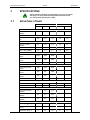
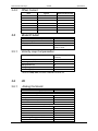
DRIVE FAMILY POWER
AC Input
S20260
DC Input
S20360
S20660
S20330
S20630
4.5
9.0
18.0
9.0
18.0
3.0
3.0
3.0
3.0
3.0
2.3
4.5
9.0
4.5
7.5
40° C amb (ARMS)
1.5
3.0
6.0
3.0
6.0
50° C amb (ARMS)
1.0
2.0
4.0
2.0
4.0
240 VAC (VA) 3
Phase
1500
3000
6000
-
-
120 VAC (VA) 1
Phase
750
1500
2400
-
-
750
1500
1
Peak Output Current (RMS)
(0 to 40°C) Amb
(ARMS)
Minimum Peak Current Time
(Starting from 0 amps)
sec
Continuous Output Current Convection2
0 to 30° C amb
(ARMS)
Peak Output Power
75 VDC (VA)
Drive Continuous Output Power
240 VAC 3 Phase
(watts)
600
1100
2000
-
-
240 VAC 1 Phase
(watts)
500
900
1500
-
-
120 VAC 1 Phase
(watts)
250
450
-
-
-
-
-
-
250
500
75 VDC (watts)
Continuous Motor Shaft Power @3000 RPM (Nominal Bus –10%)
0 to 30° C amb (watts)
300
750
1500
180
315
40° C amb (watts)
200
500
1000
125
250
RMS Line Current at Continuous Output Power
240 VAC 3 Phase
(ARMS)
2.7
5.0
9.0
-
-
240 VAC 1 Phase
(ARMS)
3.4
6.5
12.04
-
-
120 VAC 1 Phase
(ARMS)
3.4
6.5
12.04
-
-
+BUS Current – 75 VDC at Continuous Output Power
Average (ADC)
-
-
-
3.0
6.7
Instantaneous Peak
(APEAK)
-
-
-
12.7
25.5
Power Diss. at 40° C
17
29
60
8
12
S200 Reference Manual
M-SM-200-01
5
Specifications
03/2006
Danaher Motion Kollmorgen
AC Input
DC Input
S20260
S20360
S20660
S20330
S20630
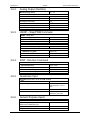
Peak Power kW (500
mSec)
4.4
@36Ω
6.4
@25Ω
10
@15Ω
-
-
Continuous Power (watts)
440
@36Ω
640
@25Ω
1000
@15Ω
-
-
Maximum Regen Duty
Cycle (%)
10
@36Ω
10 @25Ω
10 @15Ω
-
-
Regen Resistance (Ω)
25 – 50
25 – 50
12 – 50
-
-
PCONT (watts)
Shunt Regulator
Bus Capacitance Energy Absorption (joules)
340 VDC Nominal BUS
15.5
15.5
20
-
-
-
-
-
1.5
1.5
Output Current Ripple
Freq fS (kHz)
20
20
20
31.2
31.2
Minimum Motor
Inductance l-l (mH)
5
2.5
1.25
-
-
-
-
-
0.4
0.2
300
150
75
30
15
75 VDC BUS with 4,000
µf
(5 volt increase to 80
VDC)
At 75 VDC
Maximum Motor
Inductance l-l (mH)
Maximum Motor Power Cable Length4
1
18 AWG cable (m)
50
50
50
50
25
14 AWG cable (m)
50
50
50
50
50
Peak Output Current listed is for sine mode. In six-step mode, the peak
output currents are scaled to give the same output torque as in sine mode
with a pure sinusoidal Back EMF motor.
To convert ARMS to A (0-pk), multiply ARMS * 1.414.
2
Above 30o C ambient, linearly derate between provided 40o C, 50o C ratings.
At higher ambient temperatures (above 30o C) the S20360 drive needs to be
mounted on a thermally conductive surface to limit the heatsink temperature
o
to less than 75 C.
3
Single phase operation of the S20660 requires derating of continuous output
power to avoid excessive ac line front end currents.
4
See Appendix B - Cables for voltage loss vs cable length.
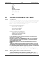
3.2
AC INPUT DRIVES - CONTROL AND POWER
3.2.1
AC Control Power Supply
6
Input Voltage Range (RMS)
85 VAC to 265 VAC single phase
47 to 63 Hz
120 VDC to 375 VDC
Ride Through Time for AC
Line Drop
85 VAC 60 Hz > 0.78 60 Hz cycles
120 VAC 60 Hz > 3.3 60 Hz cycles
240 VAC 60 Hz >18.5 60 Hz cycles
M-SM-200-01
S200 Reference Manual
Danaher Motion Kollmorgen
3.2.2
3.2.4
Specifications
AC Motor Power Supply
Input Voltage Range (RMS)
90 to 265 VAC
Phases
1 or 3
Transformer Suggested KVA
S20260: 1.5 to 2 kVA
S20360: 2.0 to 3 kVA
S20660: 3.0 to 5 kVA
Maximum AC Line KVA1
100
1
3.2.3
03/2006
Maximum AC Line is specified to limit the mains surges to the drive.
AC Bus Voltage and Faults
240 VAC Input Nominal Bus
Voltage
320 VDC
120 VAC Input Nominal Bus
Voltage
155 VDC
BUS Undervoltage Fault
Factory Default is None
BUS Overvoltge (BusOV)
Fault
407 VDC + 5%
BUS Regen Voltage
= 0.974*BusOV = 397 VDC Nominal
AC Inrush Current & Fusing
S20260
S20360
S20660
Worse Case Inrush Peak
Current at 240 VAC
140 A 0-p
140 A 0-p
240 A 0-p
Inrush pulse width
1.5 ms
1.5 ms
2.0 ms
Recommended Fusing Line
Inputs
S20260
S20360
S20660
Type – 250 VAC Time Delay Fuse
3.2.5
240 VAC 3 Phase (ARMS)
Bussmann
MDA-5
Bussmann
MDA-8
Bussmann
MDA-15
240 VAC 1 Phase (ARMS)
Bussmann
MDA-5
Bussmann
MDA-10
Bussmann
MDA-20
120 VAC 1 Phase
Bussmann
MDA-5
Bussmann
MDA-10
Bussmann
MDA-20
(ARMS)
AC Control Inrush Current & Fusing
Worse Case Inrush Peak Current at 240
VAC
3.2.6
10 A 0-p
Inrush Pulse Width
1.60 ms
Fusing – Control Inputs
Bussmann MDA – 1/2
AC Power On Delay
Control Power Applied to Drive Operational
S200 Reference Manual
M-SM-200-01
1.25 seconds
7
Specifications
03/2006
Danaher Motion Kollmorgen
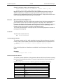
3.3
DC INPUT DRIVES - CONTROL AND POWER
3.3.1
DC Control Power Supply
Control Voltage Range (VDC)
(J1-1 to J1-2)
+10 to +90
Control Input Power (watts)1
2 to 8
1
(20 watt min supply recommended) Refer to the DC Power Supply Section
for detailed application information and requirements.
3.3.2
3.3.3
DC Bus Voltage and Faults
+BUS Voltage Range (VDC) (J1-3 to J1-2)
+20 to +90
+BUS Undervoltage Fault
+17 VDC nominal
+BUS Overvoltage Fault
+91 VDC nominal
DC Power On Delay
Control Power Applied to Drive Operational
3.4
1.5 seconds
MOTOR CURRENT CONTROL
Motor Phase Current Waveform
(In Sine or six-step mode output torque = Motor
KT*Drive IFB)
Pure sinusoidal or six-step,
depending on feedback
device
Motor Shaft Torque (Ignoring motor magnetic saturation)
Peak (hot motor winding)
Multiply KT by 1.06 for cold motor winding
(AKM or PMA motors).
Instantaneous
3.4.1
KT (N-m/ARMS)*Drive Ipeak
(ARMS)
KT (N-m/ARMS)*IFB (ARMS)
Current Loop Bandwidth
Maximum Bandwidth
AC Input Drive (kHz)
3
DC Input Drive (kHz)
5
Recommended Bandwidth
AC Input Drive (kHz)
2
DC Input Drive (kHz)
3
SFD Auto Set (kHz) AC & DC
2
Bandwidth Variation For Fixed Motor L
(% regulated independent of bus voltage)
± 2.5
Update Period (µs)
0.8
Recommended Max Motor Electrical Frequency (Hz)
8
AC Input Drive (Hz)
600
DC Input Drive (Hz)
900
M-SM-200-01
S200 Reference Manual
Danaher Motion Kollmorgen
3.4.2
3.5
3.5.1
03/2006
Specifications
Offset Current
Drive
Typical
Worst Case Over Temp
S20250
0.2% / 12 mA
0.5% / 32 mA
S20260
0.2% / 12 mA
0.5% / 32 mA
S20330
0.2% / 25 mA
0.5% / 64 mA
S20350
0.2% / 25 mA
0.5% / 64 mA
S20360
0.2% / 25 mA
0.5% / 64 mA
S20660
0.2% / 50 mA
0.5% / 128 mA
S20630
0.2% / 50 mA
0.5% / 128 mA
VELOCITY LOOP
Maximum Stable Bandwidth (Hz with SFD)
800
Update Period (µs)
0.8
Range (rpm)
0 to 18,300
Command Resolution
< 0.001 rpm analog
0.558 rpm serial
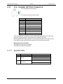
Velocity Loop Compensation
KVP Range (Depends on Ipeak)
0.00044 to 0.106 (Ipeak)
(1/rad/sec)
KVP Resolution (%)
10
KVI Range (Hz)
0, 0.0238 to 753.9
KVI Resolution (%)
10
ARF01 Range (Hz)
1.518 to 96382
1
ARF1 Range (Hz)
1
1.518 to 96382
Values for ARF0, ARF1; from 3012 to 24873 Hz cannot be set.
3.6
I/O
3.6.1
Analog Command
Maximum Differential Range (volts)
Maximum Single Ended Range (volts)
Full Scale Tolerance (%)
Worse Case
Typical
Linearity (% Full Scale)
Monotonic to
S/N Ratio Referred to Full Scale (bitsRMS)
Full A/D Bandwidth
800 Hz A/D Bandwidth
25 Hz A/D Bandwidth
Offset
Maximum Unadjusted Offset (mV)
Offset Drift (µV/° C typ.)
CMRR
S200 Reference Manual
M-SM-200-01
±12.5
-12.5 to +16.0
±3.5
±1
< 0.1
< 2-16 Full Scale
14
16
18
Adjustable to 0
50
250
> 30 dB at 60 Hz
9
Specifications
3.6.2
03/2006
Danaher Motion Kollmorgen
Analog Output (DacMon)
Maximum Range (volts)
0.5 – 4.5
Full Scale Tolerance (%)
3.6.3
Worse Case
±5
Typical
±1
Linearity (% Full Scale)
<0.1
Monotonic to
< 2-16 Full Scale
Offset (mV)
< 100
Offset Drift (µV/°C typ.)
250
HSINP – Step/PWM Command
HSINP - J4-10, J4-11
Input Voltage (volts)
3.0 – 6.0
Input Current (mA)
9.0 – 24.0
Minimum Pulse Width (ns)
250
HSINP as Step Command
Maximum Step Frequency (MHz)
1.5
HSINP as PWM Command
3.6.4
PWM Frequency (kHz)
0.25 to 250
Pulse Width
0 – 100% Duty Cycle
Pulse Width Distortion (ns)
250 maximum
SINP - Direction Command
MSINP - J4-5, J4-1
3.6.5
Input Voltage (volts)
± (4.0 - 30.0)
Input Current (mA)
0.65 - 6.7
Direction Setup Time (µs)
100
Minimum Pulse Width (µs)
200
Quadrature Input
Quadrature Input CHA - J4-19, 20 CHB J4-21,22
Type
RS-422/RS-485
Input Voltage
Differential ± (0.2 to 12) volts
Common Mode –7 to +12
volts
3.6.6
Input Termination
None internal to the drive.
Maximum Line Frequency (kHz)
625 (corresponds to 2.5 MHz
quadrature pulse rate)
General Purpose Inputs
DINP1, DINP2, DINP3 – J4-2, 3, 4
10
Input Voltage (volts)
Referenced to DINPCOM (J4-5)
± (4.0 - 30.0)
Input Current (mA)
0.65 - 6.7
Response Time
1.0 ms
M-SM-200-01
S200 Reference Manual
Danaher Motion Kollmorgen
3.6.7
03/2006
General Purpose Outputs
DOUT1, DOUT2 – J4-6,7 and J4-8,9
Maximum Output Voltage (volts)
3.6.8
Specifications
- 0.30 to 30.0
Clamp Voltage (volts)
33 V ± 6%
Maximum Output Current
50 mA
On voltage (volts)
1.0 V at 10 mA
1.2 V at 50 mA
Response Time (ms)
1.0
Quadrature Outputs
Quadrature Output CHA- J4-19, 20 CH B- J4-21,22 CHZ- J4-17,18
Type
RS-422/RS-485
3.7
Output Voltage (volts)
5.0 V Differential Output Unloaded
Hysteresis
1/2 Quadrature Count
corresponding to 1/8 Encoder
Line Count
MECHANICAL
S200 AC INPUT DRIVES
Base Drive
S20260-VT
S20360-VT
w/ Option
Card
S20260-XX
S20360-XX
Drive Height (A)
175.0 mm
6.90 in
Drive Width (B)
S200 DC INPUT DRIVES
Base Drive
S20660-XX
S20630-VT
S20330-VT
w/ Option
Card
S20630-XX
S20330-XX
175.0 mm
6.90 in
175.0 mm
6.90 in
152.4 mm
6.00 in
152.4 mm
6.00 in
54.8 mm
2.16 in
54.8 mm
2.16 in
64.0 mm
2.52 in
28.7 mm
1.13 in
48.3 mm
1.90 in
Drive Depth1 (C)
131.6 mm
5.18 in
131.6 mm
5.18 in
131.6 mm
5.18 in
100.8 mm
3.97 in
100.8 mm
3.97 in
Mounting
Hardware
M4 or #8
M4 or #8
M4 or #8
M4 or #8
M4 or #8
Drive Weight
0.77 kg
1.69 lb
0.85 kg
1.86 lb
0.82 kg
1.80 lb, w/
option card
1.97
0.40 kg
0.88 lb
0.5 kg
1.10 lb
AC3
Drive Dimensions
1
Depth measurement is for drive only. Add approximately 50.8 mm (2 in) to accommodate
mating connectors and wire bend radius.
3.8
ENVIRONMENTAL
Operating Temperature (° C) – Full Rating
Operating Temperature (° C) – Derated
Linearly Derate Continuous Current to 67% of
40o C Rating
S200 Reference Manual
M-SM-200-01
0 to 40
40 to 50
11
Specifications
03/2006
Pollution Degree
Storage Temperature (° C)
Humidity (% non-condensing)
Altitude
Danaher Motion Kollmorgen
2
-20 to 70
10 to 90
<1500 m (5000 feet)
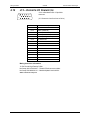
3.9
SMART FEEDBACK DEVICE (SFD)
3.9.1
Position Signal
Resolution/Rev (arc min)
Repeatability (arc min RMS)
Noise
No Filtering (arc min RMS)
150 Hz Single Pole Filtered (arc min RMS)
10 Hz Single Pole Filtered (arc min RMS)
DC Offset Temperature Drift
Absolute Accuracy
AKM1 (arc min)
AKM2 or 3, 4 (arc min)
Communications Update Period (µs)
3.9.2
< 2-17 Rev RMS = 0.16
< 2-18 Rev RMS = 0.08
< 2-19 Rev RMS = 0.02
< 2-18 Rev/° C = 0.08 arc
min/° C
± 2-10.3 Rev = ±17
± 2-11.1 Rev = ±10
51.2
Velocity Signal
Resolution (rpm)
Quanta (rpm)
Noise
No Filtering (rpm RMS)
150 Hz Single Pole Filtered (rpm RMS)
10 Hz Single Pole Filtered (rpm RMS)
DC Accuracy
Typical at 25° C (%)
Worse case (%)
Ripple
AKM1 (% p-p at 1200 rpm)
AKM2, 3, 4 (% p-p at 1200 rpm)
Offset (rpm)
Communications Update Period (µs)
Hardware Interpolation Period (µs)
12
24 bits = 0.0013
< ± 2-19 Rev = ± 0.04
M-SM-200-01
< 0.001
0.07
<4
< 0.6
< 0.06
± 0.01
± 0.05
2.5
1.5
< 0.0001
51.2
0.1
S200 Reference Manual
Danaher Motion Kollmorgen
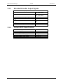
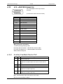
3.9.3
03/2006
Emulated Encoder Output Signals
Available Resolutions (PPR)
Binary
Decimal
Maximum Output Line Frequency (MHz)
Max Recommended Speed at 32768 PPR
(rpm)
Max Recommended Speed at 16384 PPR
(rpm)
Max Recommended Speed at 4096 PPR (rpm)
Marker Pulse Width
3.9.4
Specifications
128, 512, 1024, 2048, 4096,
8192, 16384, 32768
125, 500, 1000, 2000, 2500,
5000, 10000, 20000
2.5
2200
4600
18300
~ 1 Quadrature Pulse
General SFD Specifications
-3 dB Bandwidth (Hz)
-45° Phase Lag (Hz)
Max Tracking Rate (rpm)
Max Recommended Rate (rpm)
Max Tracking Acceleration (rpm/sec)
Maximum Feedback Cable Length
S200 Reference Manual
M-SM-200-01
> 2000
> 1000
> 48600
25000
> 16x106
50 m (164 ft)
13
Quick Start Guides
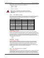
4
03/2006
Danaher Motion Kollmorgen
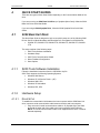
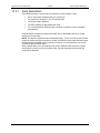
QUICK START GUIDES
There are two types of Quick Start Guides depending on the Communication Mode of the
drive.
If you are not using an S200 Base Unit Drive (no SynqNet Option Card), follow the S200
Base Unit Drive Quick Start Guide.
If you are using an S200 SynqNet Drive, follow the S200 SynqNet Drive Quick Start
Guide.
4.1
S200 BASE UNIT DRIVE
This Quick Start Guide is designed to help a user quickly setup one of the following S200
Drives. See Drive Model Numbers and Descriptions for a complete list of S200 drives.
•
S20330-VTS, S20630-VTS, S20260-VTS, S20360-VTS, S20250-VTS, S20350VTS
The setup consists of the following steps:
1. S200 Tools Software Installation
2. Hardware Setup
3. S200 Tools Communication Wizard
4. Motor Feedback Configuration
5. Save Options
4.1.1
S200 Tools Software Installation
Follow the installation instructions from the CD-ROM or zip file.
S200 Tools supports the following Operating Systems:
•
Windows 2003 Server
•
Windows XP, All Service Packs – (SP)
•
Windows 2000, SP2
•
Windows XP embedded
•
Windows NT4, SP6
4.1.2
Hardware Setup
4.1.2.1.
DRIVE SETUP
To establish a communication link between the host computer and the S200 Base Unit
drive, connect a serial communication cable between the drive and host computer.
1. Plug one end of a serial communications cable to J5 (SynqNet IN) of the S200
drive and the other end of the cable to the host computer's serial COM port.
NOTE: The serial communications cable is not shipped with the drive. It must be
ordered separately.
14
M-SM-200-01
S200 Reference Manual
Danaher Motion Kollmorgen
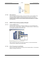
4.1.2.2.
03/2006
Quick Start Guides
MOTOR SETUP
If you are using an S200 Base Unit drive, use the J3 connector for motor feedback. Only
SFD motor feedback is supported on Base Unit drives. If you want to use SinCos or
ComCoder as motor feedback, you must use the AUX FB (J14) connector, which is not
available on Base Unit drives. See Drive Model Numbers and Descriptions for a complete
list of S200 drives.
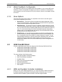
4.1.3
4.1.3.1.
S200 Tools Communications Wizard
LAUNCH S200 TOOLS
Launch the S200 Tools program by clicking the desktop icon or from the Windows Start
button (Programs > Danaher Motion > S200Tools). The default location for S200Tools.exe,
is (C:\Program Files\Danaher Motion\S200Tools).
When the S200 Tools program is launched for the first time, no drives should be listed
under the Online or Offline Communications Mode.
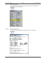
4.1.3.2.
START COMMUNICATION WIZARD
Open the Communication Wizard by selecting it from the toolbar (Utilities > Communication
Wizard) or clicking the shortcut icon.
S200 Reference Manual
M-SM-200-01
15
Quick Start Guides
03/2006
Danaher Motion Kollmorgen
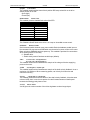
Select Serial as the Communications Mode and select the appropriate COM port.
If you do not know which type of drive is connected, click the Test button. The returned
message will either say that there is no connection, confirm that you have an S200
connected, or tell you that the connected node is NOT an S200 drive.
Troubleshooting
If you receive the "No Connection" message, check the hardware connections.
After you have confirmed your setup, click the OK button.
The installed S200 drive(s) will now be listed as "Online" and will list its configuration and
status options.
16
M-SM-200-01
S200 Reference Manual
Danaher Motion Kollmorgen
4.1.4
03/2006
Quick Start Guides
Motor Feedback Configuration
The S200 Base Unit drives only support SFD motor feedback. If you are using SFD motor
feedback, no further configuration is needed. If you want to use SinCos or ComCoder as
motor feedback, you must use the AUX FB (J14) connector, which is not available on Base
Unit drives.
4.1.5
Save Options
There are three types of Save options. It is important to know how to use each type to
ensure that configurations are not lost.
4.2
•
Download NV – This button will save the parameter settings displayed in S200
Tools to the selected drive. These parameters are saved to the drive's permanent
memory and are recalled during a power-up cycle.
•
Download Drive – This button will save the parameter settings displayed in S200
Tools to the selected drive/node. However, unlike Download NV, these parameters
are only saved to the drive's temporary RAM and will not be recalled at a power-up
cycle. It is recommended that you use the Download Drive button when testing
settings. Once you are satisfied with the settings, click the Download NV button to
permanently save the settings to the drive.
•
Save/Save As – You can also save the settings of a drive as a configuration file
(*.S2C). Remember, saving a configuration file does NOT save the settings to the
drive. Configuration files can be helpful for saving multiple drive setups. You can
easily download a setting to a drive by opening the configuration file in the Offline
mode and clicking the Download NV/Drive buttons once the proper drive is
selected in the Online mode. It is recommended that you save a configuration file
for each setup.
S200 SYNQNET DRIVE
Follow the instructions below if you are using one of the following S200 Series Drives:
•
S20250-SRS, S20260-SRS, S20350-SRS,
S20360-SRS, S20330-SRS, S20630-SRS,
S20250-SDS, S20260-SDS, S20350-SDS,
S20360-SDS, S20330-SDS, S20630-SDS
The setup consists of the following steps:
1. MDK and SynqNet Controller Installation
2. S200 Tools Software Installation
3. Hardware Setup
4. S200 Tools Communication Wizard
5. SynqNet Configuration
6. Motor Feedback Configuration
7. Save Options
4.2.1
MDK and SynqNet Controller Installation
Before you can use an S200-SynqNet Drive, you must first install the Motion Developer's
Kit Software package and SynqNet controller from Motion Engineering Inc. For more
information about installation, please see MEI's Technical Support website.
S200 Reference Manual
M-SM-200-01
17
Quick Start Guides
4.2.2
03/2006
Danaher Motion Kollmorgen
S200 Tools Software Installation
Follow the installation instructions from the CD-ROM or zip file. See S200 Tools Software
Installation Guide.
S200 Tools supports the following Operating Systems:
•
Windows 2003 Server
•
Windows XP, All Service Packs - (SP)
•
Windows 2000, SP2
•
Windows XP embedded
•
Windows NT4, SP6
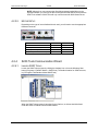
4.2.3
Hardware Setup
4.2.3.1.
DRIVE SETUP
NOTE: The drive serial port (J5) is disabled on SynqNet drives.
If you are using an S200 SynqNet Drive, you need to establish SynqNet communication
link between the S200 SynqNet Drive and the SynqNet motion controller.
1. Plug one end of an Ethernet communications cable to J11 (SynqNet IN) of the
S200 drive and the other end to the SynqNet controller's OUT port.
2. One Drive/Node
Use another Ethernet communications cable to connect J12 (SynqNet OUT) of the
S200 drive to the XMP-SynqNet controller's SynqNet IN port.
Multiple Drives/Nodes
Connect an Ethernet communications cable from the XMP-SynqNet controller's
OUT port to the SynqNet IN port (J11) of the first drive/node. Connect an Ethernet
cable from the node's SynqNet OUT port (J12) to the SynqNet IN port (J11) of the
next node. Connect another cable from the SynqNet OUT port (J12) of the last
node in the topology to the SynqNet IN port of the XMP-SynqNet controller.
18
M-SM-200-01
S200 Reference Manual
Danaher Motion Kollmorgen
03/2006
Quick Start Guides
NOTE: Although you can connect other SynqNet supported nodes/drives on the
SynqNet network, you will only be able to configure the S200 Series Drives with the
S200 Tools software. S200 Tools will only communicate with S200 Series Drives.
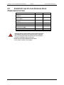
4.2.3.2.
MOTOR SETUP
Depending on the type of motor feedback that is used, you will need to use the appropriate
feedback connector.
Motor Feedback
J3 Feedback
J14 AUX FB
X
-
X
X
X
SFD
SinCos (with Endat 2.1)
SinCos (with Halls)
ComCoder (Incremental + Halls)
4.2.4
S200 Tools Communication Wizard
4.2.4.1.
LAUNCH S200 TOOLS
Launch the S200 Tools program by clicking the desktop icon or from the Windows Start
button (Programs > Danaher Motion > S200Tools). The default location for S200Tools.exe,
is (C:\Program Files\Danaher Motion\S200Tools).
When the S200 Tools program is launched for the first time, no drives should be listed
under the Online or Offline Communications Mode.
S200 Reference Manual
M-SM-200-01
19
Quick Start Guides
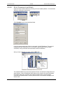
4.2.4.2.
03/2006
Danaher Motion Kollmorgen
START COMMUNICATION WIZARD
Open the Communication Wizard by selecting it from the toolbar (Utilities > Communication
Wizard) or clicking the shortcut icon.
Select SynqNet as the Communications Mode.
If you do not know which type of drive is connected, click the Test button. The returned
message will either say that there is no connection, confirm that you have an S200
connected, or tell you that the connected node is NOT an S200 drive.
After you have confirmed your setup, click the OK button.
The installed S200 drive(s) will now be listed as "Online" and will list its configuration and
status options. If there are additional S200 nodes on the network, they are automatically
discovered. When using a network with multiple SynqNet nodes, use the SynqNet
controller/node pulldown bars to select a particular node on the network to display in the
Online mode.
20
M-SM-200-01
S200 Reference Manual
Danaher Motion Kollmorgen
03/2006
Quick Start Guides
NOTE for SynqNet: Although the S200 Tools software maintains communication with all
properly connected S200 drives drives on the SynqNet network, only one SynqNet node
will be displayed at a time under the Online display.
4.2.5
SynqNet Configuration
The next step is to set the proper drive and motor feedback configurations.
Under the SynqNet Options tab, select the source for motor feedback (Feedback Source).
Select Base Unit Feedback if the motor feedback is connected to J3 on the S200 Drive.
Select Option Card Feedback if the motor feedback is connected to J14 on the S200
Drive.
4.2.6
Motor Feedback Configuration
The next step is to set the proper motor feedback configurations.
4.2.6.1.
SFD
If you are using SFD motor feedback, no further configuration is needed.
4.2.6.2.
SINCOS OR COMCODER
If you are using SinCos or ComCoder as motor feedback, use the equations below to
determine the appropriate parameters for setup.
Kip
Kip = 2*PI()*2000*(motor line to line inductance)
Ex: l-l inductance = 0.018 H
Kip = 2*PI()*2000*(0.018)
Kip = 226 V/A
S200 Reference Manual
M-SM-200-01
21
Quick Start Guides
03/2006
Danaher Motion Kollmorgen
I2TF0
I2TF0 = 5/(2*PI()*(motor time constant in minutes)*60))
Ex: Mtc = 20 minutes
I2TF0 = 5/(2*PI()*20*60)
I2TF0 = 0..000663 Hz
I2TTrip
I2TTrip = (motor continuious current)*1.25
Ex: Ics = 4 Arms
I2TTrip = 4*1.25
I2TTrip = 5 Arms
ILmtPlus
ILmtPlus = (motor peak current)/(drive peak current)*100
Ex: Motor Ip = 4.5 Arms, Drive Ip = 9 Arms
Motor Ip = (4.5/9)*100
Motor Ip = 50%
ILmtMinus
Typically ILmtMinus is set to the same value as ILmtMPlus. Although there can be
asymetrical current limits in the drive.
Dpoles
Dpoles = motor poles
4.2.7
Save Options
There are three types of Save options. It is important to know how to use each type to
ensure that configurations are not lost.
22
•
Download NV - This button will save the parameter settings displayed in S200
Tools to the selected drive. These parameters are saved to the drive's permanent
memory and are recalled during a power-up cycle.
•
Download Drive - This button will save the parameter settings displayed in S200
Tools to the selected drive/node. However, unlike Download NV, these parameters
are only saved to the drive's temporary RAM and will not be recalled at a power-up
cycle. It is recommended that you use the Download Drive button when testing
settings. Once you are satisfied with the settings, click the Download NV button to
permanently save the settings to the drive.
•
Save/Save As - You can also save the settings of a drive as a configuration file
(*.S2C). Remember, saving a configuration file does NOT save the settings to the
drive. Configuration files can be helpful for saving multiple drive setups. You can
easily download a setting to a drive by opening the configuration file in the Offline
mode and clicking the Download NV/Drive buttons once the proper drive is
selected in the Online mode. It is recommended that you save a configuration file
for each setup.
M-SM-200-01
S200 Reference Manual
Danaher Motion Kollmorgen
5
03/2006
Mounting the Drive
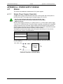
MOUNTING THE DRIVE
The S200 drives are designed for operation in a cabinet using the following installation
instructions:
Mount the drives vertically inside a cabinet on a flat, solid, electrically conductive
mounting surface that is connected to PE (Protective Earth Ground) and capable
of supporting the weight of the unit.
Provide a good connection to PE. Remove the paint on the mounting surface over
an area extending at least 12 mm (0.5 in) from the mounting bolts to achieve good
electrical connection over a large area between the drive and grounded mounting
surface.
Ensure that the environment within the cabinet meets the requirements listed in
the Specifications.
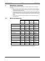
5.1
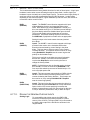
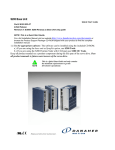
MOUNTING DIMENSIONS
AC INPUT DRIVES
AC1, AC2
AC3
Drive Dimensions
Drive Height (A)
Drive Width (B)
Drive Depth1 (C)
Clearance Requirements
Top and Bottom (D)
Side to Side (E)
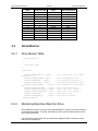
Mounting Dimensions
Horizontal Mounting Offset
(F)
Vertical Mounting Offset
(G)
Vertical Mounting Height
(H)
Drive to Drive Mounting (J)
Mounting Hardware
Drive Weight
DC INPUT DRIVES
DC Base
w/ Option
Drive
S20330-VTS S20330-XX
S20630-VTS S20630-XX
S20260-VTS
S20360-VTS
S20660-XX
175.0 mm
6.90 in
54.8 mm
2.16 in
131.6 mm
5.18 in
175.0 mm
6.90 in
64.0 mm
2.52 in
131.6 mm
5.18 in
152.4 mm
6.00 in
28.7 mm
1.13 in
100.8 mm
3.97 in
152.4 mm
6.00 in
48.3 mm
1.90 in
100.8 mm
3.97 in
25.4 mm
1.0 in
25.4 mm
1.0 in
25.4 mm
1.0 in
25.4 mm
1.0 in
12.7 mm
0.50 in
12.7 mm
0.50 in
12.7 mm
0.50 in
12.7 mm
0.50 in
25.6 mm
1.01 in
4.3 mm
0.17 in
166.4 mm
6.55 in
80.3 mm
3.16 in
M4 or #8
0.77 kg
1.69 lb
25.6 mm
1.01 in
4.3 mm
0.17 in
166.4 mm
6.55 in
87.3 mm
3.16 in
M4 or #8
0.85 kg
1.86 lb
24.6 mm
0.97 in
4.1 mm
0.16 in
144.3 mm
5.68 in
41.40 mm
1.63 in
M4 or #8
0.40 kg
0.88 lb
24.6 mm
0.97 in
4.1 mm
0.16 in
144.3 mm
5.68 in
60.96 mm
2.40 in
M4 or #8
0.5 kg
1.10 lb
1
Depth measurement is for drive only. Add approximately 50.8 mm (2 in) to depth
given in the table to accommodate mating connectors and wire bend radius.
S200 Reference Manual
M-SM-200-01
23
Mounting the Drive
03/2006
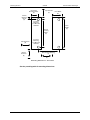
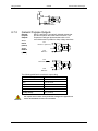
Horizontial
M ounting Offset
(F)
Vertical
M ounting
Offset
(G)
Top Clearance
(D)
Danaher Motion Kollmorgen
Drive W idth
(B)
For Drive
M ounting
use M 4 or #8
Hardw are
Vertical
M ounting
Height
(H)
Side Clearance
(E)
Bottom
Clearance
(D)
Drive
Height
(A)
For Drive
M ounting
use M 4 or #8
Hardw are
Drive to Drive M ounting
(J)
Side Clearance
(E)
Mounting Dim ensions - Front View
See the preceding table for mounting dimensions.
24
M-SM-200-01
S200 Reference Manual
Danaher Motion Kollmorgen
5.2
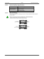
5.2.1
03/2006
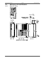
Mounting the Drive
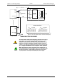
MECHANICAL OUTLINE DRAWINGS
Base AC Drive
S200 Reference Manual
M-SM-200-01
25
Mounting the Drive
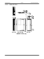
5.2.2
26
03/2006
Danaher Motion Kollmorgen
Base DC Drive
M-SM-200-01
S200 Reference Manual
Danaher Motion Kollmorgen
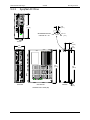
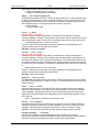
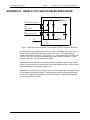
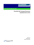
5.2.3
03/2006
Mounting the Drive
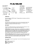
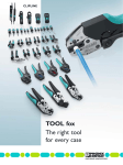
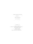
SynqNet AC Drive
5.18
[ 131.57 ]
0.18
[ 4.57 ]
Ø
RECOMMENDED MOUNTING
HARDWARE: #8 or M4
0.18
[ 4.57 ]
TOPVIEW
1.01
[ 25.56 ]
2.16
[ 54.75 ]
0.17
[ 4.32 ]
6.89
[ 175.01 ]
FRONT VIEW
RIGHTSIDEVIEW
6.55
[ 166.37]
REARVIEW
0.17
[ 4.32 ]
DIMENSIONS ARE IN INCHES [MM]
S200 Reference Manual
M-SM-200-01
27
Mounting the Drive
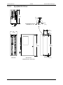
5.2.4
03/2006
Danaher Motion Kollmorgen
SynqNet DC Drive
3.97
[ 100.84 ]
0.18
[ 4.57 ]
Ø 0.18
RECOMMENDED MOUNTING
HARDWARE: #8 or M4
[ 4.57 ]
TOPVIEW
0.97
[ 24.64 ]
1.90
[ 48.26 ]
0.16
[ 4.06 ]
6.00
[ 152.40 ]
FRONT VIEW
RIGHT SIDEVIEW
5.68
[ 144.27 ]
REARVIEW
0.16
[ 4.06 ]
DIMENSIONS ARE IN INCHES [MM]
28
M-SM-200-01
S200 Reference Manual
S200 Reference Manual
M-SM-200-01
DINP COM
9
10
8
7
5
6
4
3
2
1
23
22
21
20
19
18
17
16
15
14
13
NC
TX232
I/O RTN
I/O RTN
RX232
NC
I/O RTN
6
5
4
3
2
1
26
24
ANA CMD25
ANA CMD+
I/O RTN
CH B OUT / CH B IN
CH B OUT / CH B IN
CH A OUT / CH A IN
CH A OUT / CH A IN
CH Z OUT
CH Z OUT
I/O RTN
DAC MON2
DAC MON1
I/O RTN
11
SFD BAT+
12
HSINP1-
HSINP1+ (STEP/PWM)
DOUT2DOUT2+ (RUN)
DOUT1DOUT1+ (FAULT)
MSINP1 (DIRECTION)
DINP3 (INHIBIT-)
DINP2 (INHIBIT+)
DINP1 (ENABLE)
J4
J5
COMMAND I/O
SERIAL
PORT
AC
INPUT
DRIVE
S200
J3
J2
J1
9
8
7
6
5
4
3
2
1
4
3
2
1
6
5
4
3
2
1
36 Ohm
Optional
External
Regen Resistor
240/120 VAC
47 - 63 Hz
240/120 VAC
47 - 63 Hz
MOTOR
SFD OR
HALLS
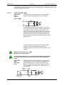
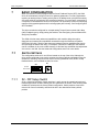
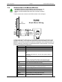
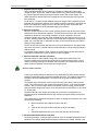
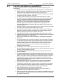
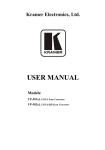
Notes:
1. For S2xx50 voltager doubler models see
Appendix for ac line interface details.
2. The motor and feedback cable shielding
shown is for individual cables. Kollmorgen
also offers a combined motor and feedback
cable.
L1 240/120 VAC NEUTRAL
L2 240/120 VAC HOT
L3 240 VAC
C1 CTRL VAC
C2 CTRL VAC
+BUS
-BUS
REGEN
PE
PHASE U
PHASE V
PHASE W
PE
NC/CW
NC/CV
SFD COM+/CU
SFD COM-
SFD +5 RTN
SFD +5V
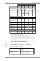
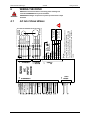
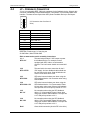
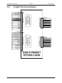
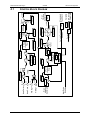
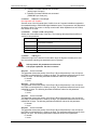
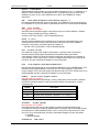
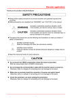
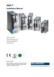
6.1
FEEDBACK
WARNING
MOTOR
POWER
6
AC
POWER
Danaher Motion Kollmorgen
03/2006
Wiring the Drive
WIRING THE DRIVE
READ these instructions before connecting power. Damage can
result from MISWIRING at the power terminals.
DANGEROUS voltages are present on power input and motor output
terminals.
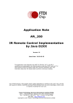
AC INPUT DRIVE WIRING
29
Wiring the Drive
6.2
03/2006
Danaher Motion Kollmorgen
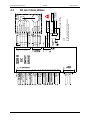
J1 – AC INPUT DRIVE POWER
The S200 AC input drives are capable of direct line operation. All units are fully isolated
and do not require external isolation transformers. The inrush current on the connection to
the line is internally limited to a safe level for the drive. There are no voltage selection or
ranging switches required to operate within the specified voltage input ranges.
The S200 series drives are functionally compatible with all standard forms of three phase
AC lines:
Grounded neutral WYE
Open-Delta Grounded Leg
TEE
NOTE
The customer is responsible for supplying the appropriate fuses or
circuit breakers in the J1 AC motor power lines to comply with local
electrical codes.
The control input power required is between 5 and 10 watts. The AC input motor power
depends on output power and losses in the power stage.
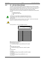
CAUTION
On AC input drives, J1 is a 9 pin pluggable connector.
1
9
(J1 Connector view from front of drive).
Pin
J1-1
J1-2
J1-3
J1-4
J1-5
J1-6
J1-7
J1-8
J1-9
Description
PE (Protective Earth)
REGEN
-BUS
+BUS
C2 CTRL VAC
C1 CTRL VAC
L3 240 VAC
L2 240/120 VAC
L1 240/120 VAC
Mating Connector Information
Screw Terminal Connector
12 – 24 AWG Wire Range, Phoenix MSTB2,5/9-STF-5,08-BK
OR
Spring Cage Clamp Connector
12 – 24 AWG Wire Range, Phoenix FKC 2,5/9-SFT-5,08-BK
OR
Crimp Connector
Crimp Shell
14-20 AWG Wire Range, Phoenix MSTBC 2,5/9-STZF-5,08-BK
Crimp Contact
14-16 AWG Wire Range, Phoenix MSTBC-MT 1,5-2,5
Crimp Contact
30
M-SM-200-01
S200 Reference Manual
Danaher Motion Kollmorgen
03/2006
Wiring the Drive
18-20 AWG Wire Range, Phoenix MSTBC-MT 0,5-1,0
Refer to http://www.phoenixcon.com.
CAUTION
WARNING
NOTE
WARNING
To avoid damage to the connector and drive, NEVER plug or unplug J1 with
power applied.
J1-1 PE
Protective Earth
This chassis ground point must be connected to
Protective Earth ground. The connection at the
Protective Earth ground end must be hard wired
(do not use a pluggable connection). A ground
fault detector (RCD) cannot be depended on for
safety.
J1-2
REGEN
Connection for an optional regeneration power
resistor to absorb regenerated energy from the
motor. Models S20260 and S20360 typically use
36 Ω. S20660 typically uses 12.5 Ω, although
other values within the minimum resistance
specification can be used. Use a Wire wound
resistor with 1500 VRMS isolation between
terminals and case. Many applications do not
require a regen resistor. If over-voltage faults
occur during motor deceleration, then the more
kinetic energy is being returned to the bus
capacitors than they can handle. Connect the
proper ohmage 50 to 300 watt power resistor from
this terminal, to terminal J1-4 (+BUS) in order to
eliminate the over-voltage faults. The power rating
of the regen resistor depends on the amount of
regenerated energy that needs to be dissipated.
The regen input is not short circuit protected. The regen resistance MUST
be within specified ranges to prevent damage to the drive. For example,
between 25 to 50 Ω for the S20260, S20360 drives.
For safety, either mount the external resistor on a grounded panel or wire it
to a grounded connection. The terminals of the resistor MUST NOT be
grounded.
Wait 5 minutes after power is removed for the bus cap voltage to decay to a
safe level before touching the regen resistor or wiring. Monitor the voltage
on the bus caps with a voltmeter from +BUS (J1-4) to -BUS (J1-3).
J1-3
-BUS
The -BUS terminal is usually left open during
normal operation. In special multi-axis applications,
drive buses can be wired in parallel to allow
returned energy from one motor to power another
and limit high regen powers.
J1-4
+BUS
The +BUS terminal is used with the J1-2, REGEN,
terminal to add a regen resistor to the drive to
absorb regenerated energy.
J1-5, J1-6
C2 CTRL VAC
C1 CTRL VAC
These terminals connect 120/240 VAC power to the
drive’s control voltage power supply.
S200 Reference Manual
M-SM-200-01
31
Wiring the Drive
03/2006
Danaher Motion Kollmorgen
Input Voltage Range (RMS)
85 VAC to 265 VAC single phase
47 to 63 Hz
120 VDC to 375 VDC
Inrush Peak Current
10 A 0-p with 240 VAC Input
Inrush pulse width
1.60 ms
Fusing
Bussmann MDA – ½
For maximum ride through capability a 240 VAC input is recommended.
NOTE
J1-7, J1-8, J1-9
L3 240 VAC
L2 240/120 VAC
L1 240/120 VAC
These terminals connect 120/240 VAC power to the
drive’s output power stage BUS.
For single-phase operation, 120/240 use inputs J1-8, L2,
and J1-9, L1.
Input Voltage Range
Phases
Transformer
Maximum AC Line
Inrush Peak Current a
Inrush pulse width
1
90 to 265 VAC
1 or 3
2 to 3 KVA – recommended KVA if
transformer is required.
100 KVA1
140 A 0-p with 240 VAC input
1.5 ms
Maximum AC Line is specified to limit the mains surges to the drive.
Recommended Fusing Line
Inputs
S20260
S20360
S20660
Type – 250 VAC Time Delay Fuse
32
240 VAC 3 Phase (ARMS)
Bussmann
MDA-5
Bussmann
MDA-8
Bussmann
MDA-15
240 VAC 1 Phase (ARMS)
Bussmann
MDA-5
Bussmann
MDA-10
Bussmann
MDA-20
120 VAC 1 Phase
Bussmann
MDA-5
Bussmann
MDA-10
Bussmann
MDA-20
(ARMS)
M-SM-200-01
S200 Reference Manual
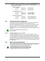
M-SM-200-01
DINP COM
9
10
8
7
5
6
4
3
2
1
22
21
20
19
18
17
16
15
14
13
NC
6
5
4
3
2
1
26
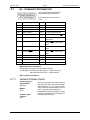
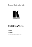
J4
J5
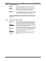
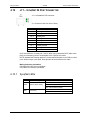
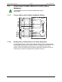
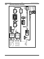
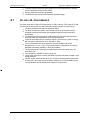
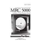
DC
INPUT
DRIVE
S200
J3
J2
J1
3
2
1
4
3
2
1
6
5
4
3
2
1
TB1
+CTRL
+BUS
BUS/CTRL GND
+
-
+
Main Power
20 - 90 VDC
Control Power
10 - 90 VDC
Alternate Dual Supply Wiring
3
2
1
- Main Power
+ 20 - 90 VDC
MOTOR
SFD OR
HALLS
I/O RTN and BUS/CTRL GND pins are
connected together in the drive
NOTE:
CHASSIS/PE
+BUS
BUS/CTRL GND
+CTRL
PHASE U
PHASE V
PHASE W
GND
NC/CW
NC/CV
SFD COM+/CU
SFD COM-
SFD +5 RTN
SFD +5V
03/2006
TX232
I/O RTN
I/O RTN
RX232
NC
I/O RTN
24
ANA CMD25
I/O RTN 23
ANA CMD+
CH B OUT / CH B IN
CH B OUT / CH B IN
CH A OUT / CH A IN
CH A OUT / CH A IN
CH Z OUT
CH Z OUT
I/O RTN
DAC MON2
DAC MON1
I/O RTN
11
SFD BAT+
12
HSINP1-
HSINP1+ (STEP/ PWM)
DOUT2DOUT2+ (RUN)
DOUT1DOUT1+ (FAULT)
MSINP1 (DIRECTION)
DINP3 (INHIBIT-)
DINP2 (INHIBIT+)
DINP1 (ENABLE)
COMMAND I/O
SERIAL
PORT
FEEDBACK
MOTOR
POWER
S200 Reference Manual
DC
POWER
6.3
DC
POWER
Danaher Motion Kollmorgen
Wiring the Drive
DC INPUT DRIVE WIRING
33
Wiring the Drive
6.4
03/2006
Danaher Motion Kollmorgen
J1 – DC INPUT DRIVE POWER
The S200 DC input drives should be powered from power supplies with reinforced isolation.
On DC input drives, J1 is a 3 pin pluggable connector.
Pin
1
3
(J1 Connector view
from front of drive).
CAUTION
Description
J1-1
+CTRL
J1-2
BUS/CTRL GND
J1-3
+BUS
To avoid damage to the connector and drive, NEVER plug or unplug J1 with power
applied.
Mating Connector Information
Screw Terminal Connector
12 – 24 AWG Wire Range, Phoenix MSTB2,5/3-STF-5,08-BK
OR
Spring Cage Clamp Connector
12 – 24 AWG Wire Range, Phoenix FKC 2,5/3-SFT-5,08-BK
OR
Crimp Connector
Crimp Shell
14-20 AWG Wire Range, Phoenix MSTBC 2,5/3-STZF-5,08-BK
Crimp Contact
14-16 AWG Wire Range, Phoenix MSTBC-MT 1,5-2,5
Crimp Contact
18-20 AWG Wire Range, Phoenix MSTBC-MT 0,5-1,0
Refer to www.phoenixcon.com.
Control power input. The DC drive accepts +10 to +90 VDC
J1-1
on this input referenced to J1-2. An isolated regulated or
+CTRL
isolated unregulated power supply can be used. This input can
be connected to +Bus input (J1-3) and powered by the same
supply as +Bus. The control power supply should be rated for
20 watts. While the power drain typically is 2 W to 8 W, a 20 W
supply ensures reliable starting of the drive.
Power return for the control and BUS power supplies. The
J1-2
BUS/CTRL GND is connected to I/O RTN internally in the drive.
BUS/CTRL
GND
Main power input to the drive. The DC drive accepts +20 to
J1-3
+90 VDC on this input referenced to J1-2. An isolated regulated
+BUS
or isolated unregulated power supply can be used. The +Bus
power drain with +Bus voltage at 75 VDC is in the range shown
below. It varies according to the application and motor.
+Bus
Continuous Power
+Bus
Peak Power
34
S20330 (3 Amp)
S20630 (6 AMP)
250 watt
500 watt
750 watt
1,500 watt
M-SM-200-01
S200 Reference Manual
Danaher Motion Kollmorgen
NOTE
Wiring the Drive
Refer to the DC Power Supply Requirements section for detailed requirements
selecting a compatible power supply.
PE
Screw
Connection
6.4.1
03/2006
Protective Earth connection point. This chassis ground point
must be connected to Protective Earth ground. The
connection at the Protective Earth ground end must be hard
wired (do not use a pluggable connection).
DC Power Supply Requirements
Bus Voltage (J1-3 to J1-2)
BUS Supply Current
S20330 Continuous Peak
(3 sec)
S20630 Continuous Peak
(3 sec)
BUS Supply Current
S20330 Continuous Peak
(3 sec)
S20630 Continuous Peak
(3 sec)
S200 Reference Manual
+ 20 VDC to + 90 VDC
48 VDC BUS
3.3 ADC at
160 W
10 ADC at
480 W
6.7 ADC at
320 W
20 ADC at
960 W
48 VDC BUS
3.3 ADC at
160 W
10 ADC at
480 W
6.7 ADC at
320 W
20 ADC at
960 W
M-SM-200-01
75 VDC BUS
3.3 ADC at 250 W
10 ADC at 750 W
6.7 ADC at 500 W
20 ADC at 3,000 W
75 VDC BUS
3.3 ADC at 250 W
10 ADC at 750 W
6.7 ADC at 500 W
20 ADC at 3,000 W
35
Wiring the Drive
03/2006
Bus Supply
Characteristics
Danaher Motion Kollmorgen
The BUS Supply should have the following characteristics:
Must provide safety isolation from the power line.
Can be regulated or unregulated.
Bus Supply Return is connected to the Control Supply
Return and I/O RTN in the drive.
Typical BUS Supply:
Unregulated, Isolating, step-down transformer with
secondary rectified into capacitive filter.
BUS Supply Return is connected to earth ground.
Wiring from BUS
Supply to Drive
Control Voltage
(J1-1 to J1-2)
10 ft maximum
16 AWG (minimum)
Twisted pair
Daisy chaining of multiple drive OK.
No contactor or switching in the BUS wiring.
+ 10 VDC to +90 VDC
Control Supply Type
Isolating
Unregulated or Regulated
Common GND with bus supply and I/O RTN.
20 watt supply or 1 amp short circuit.
Control Supply Wiring
Wire control (J1-1) to bus (J1-3)
or
Wire control (J1-1) to separate supply to preserve status
and fault information. (+ 10 VDC to + 30 VDC supply can be
shared by Control and I/O)
Control Supply
Current
6.4.2
20 to 110 mA at 75 VDC
60 to 330 mA at 24 VDC
125 to 660 mA at 12 VDC
Bus Voltage
Bus voltage outside the operating range (20 to 90 V) causes an undervoltage or
overvoltage fault. Undervoltage and overvoltage faults are self-cleared when the fault
conditions are cleared.
NOTE
Do Not allow the Bus Voltage to exceed + 90 VDC as it can
damage the drive.
Target design center voltage for unregulated supply is +70 to
+75 VDC. This provides 15 to 20 VDC margin for line tolerance, transformer regulation, and
regen pump up. Design center voltage for a regulated supply can be up to +80 VDC.
6.4.3
Control Voltage
The control voltage range for normal operation is +10 VDC to +90 VDC. The control
voltage can either be wired to the bus voltage so one supply can power the drive, or from a
separate supply. Separately powering the control from the bus allows the bus to be
powered down for safety while drive status and fault information remain available.
NOTE: Control and I/O can share a single +10 VDC to +30 VDC power supply.
NOTE
36
Do NOT allow the Control Voltage to exceed + 90 VDC as it
can damage the drive.
M-SM-200-01
S200 Reference Manual
Danaher Motion Kollmorgen
6.4.4
03/2006
Wiring the Drive
Grounding
Provide safety isolation with the external bus and control supplies from the power line.
NOTE
The drive cannot be powered from an electrically Hot supply
as it does not contain an isolation barrier.
The Ctrl and Bus voltages and non-opto coupled I/O grounds (I/O RTN) are commoned
inside the drive. The Ctrl and Bus power supplies share a ground pin (Bus/Ctrl Gnd). Join
and connect to the negative terminals of the Ctrl and Bus power supplies. The I/O RTNs
are normally connected to the signal ground of the system. (Some of the I/O is opto
coupled and have separate returns. Be sure to thoroughly review this document for details.)
The power supply negative terminal should be grounded somewhere in the cabinet. The
chassis should also be grounded. In normal operation there should be no significant
voltage between ground and the Bus/Ctrl Gnd and I/O RTNs.
NOTE
6.4.5
The maximum voltage allowed between Bus/Ctrl Gnd and
chassis is 100 VDC.
Bus Capacitance
There is a minimum requirement on the output capacitance of the bus power supply for the
S200 DC Input Drives. This capacitor is needed to absorb energy during motor
deceleration and motor disable. It also helps provide energy during motor acceleration. For
multiple S200 drives operated from one supply, the recommendation is to increase the
capacitance according to the number of drives. For example, for four 6 A / 18 ARMS DC
S200 drives powered from one 75 VDC supply, the recommended minimum bus output
capacitance of the supply is 4 x 4,000 µf = 16,000 µf. Bus capacitor voltage rating should
be 100 V. Bus capacitor type is aluminum electrolytic.
6.4.6
Bus Switching and Fusing
Do NOT put E-Stop switches or contactors between the drive bus pin (J1-3) and the power
supply bus capacitor. There is a risk of damage to the drive if the bus is disconnected from
the power supply capacitor when the drive is enabled. The motor does not need to be
rotating to regenerate energy. The motor windings store magnetic energy that regenerates
back to the supply when the drive is disabled.
E-stop switches can safely be located in series with the primary winding of a step down
transformer. If individual axis E-Stop switches are required, connect a local (unswitched)
capacitor (1,000 µf, 100 V) across the drive bus terminals (J1-3 to J1-2). If the buses of
individual drives are to be fused, select the fuse type and rating for high margin.
S20330 (3 amp)
7 A, Slo-Blo (Bussmann MDA-7)
S200 Reference Manual
S20630 (6 amp)
15 A, Slo-Blo (Bussmann MDA-15)
M-SM-200-01
37
Wiring the Drive
6.5
03/2006
Danaher Motion Kollmorgen
J2 – MOTOR POWER CONNECTOR
J2 is a 4 pin pluggable connector.
(J2 Connector view from front of
drive).
4
1
Pin
J2-1
Description
S200 AC Input Drives: PE (Physical Earth)
S200 DC Input Drives: BUS/CTRL GND
J2-2
Motor Phase W
J2-3
Motor Phase V
J2-4
Motor Phase U
Mating Connector Information
Screw Terminal Connector
12 – 24 AWG Wire Range, Phoenix MSTB2,5/4-STF-5,08-BK
OR
Spring Cage Clamp Connector
12 – 24 AWG Wire Range, Phoenix FKC 2,5/4-SFT-5,08-BK
OR
Crimp Connector
Crimp Shell
14-20 AWG Wire Range, Phoenix MSTBC 2,
5/4-STZF-5,08-BK
Crimp Contact
14-16 AWG Wire Range, Phoenix MSTBC-MT 1,5-2,5
Crimp Contact
18-20 AWG Wire Range, Phoenix MSTBC-MT 0,5-1,0
Refer to www.phoenixcon.com.
J2-1 PE
Motor Case
Ground
On S200 AC Input Drives this point is connected to
Chassis Ground.
On S200 DC Input Drives this point is connected to
BUS/CTRL GND.
In either case this termination provides a convenient
point for the motor ground connection and motor
power wire shield.
Local electrical code may require using the Earth
Ground Chassis stud for this function.
J2-2, 3, 4
Motor Phases
NOTE
38
These three terminals provide the 3-phase power
output to the motor.
Observe motor polarity, connect phase U on the drive to phase U
on the motor, etc.
For nonstandard motor drive combinations consult the factory for
proper phase orientation.
M-SM-200-01
S200 Reference Manual
Danaher Motion Kollmorgen
6.6
03/2006
Wiring the Drive
J3 – FEEDBACK CONNECTOR
J3 is a 6-pin pluggable IEEE 1394 style connector for the feedback device. Although this
connector mechanically accepts standard IEEE 1394 cables, it is electrically not a 1394
interface. The base drive accepts either SFD (Smart Feedback Device) or Hall inputs.
1
2
3
4
5
6
(J3 Connector view from front of
drive)
Pin
Description
J3-1
SFD +5 V (200 mA)
J3-2
SFD +5 RTN
J3-3
SFD COM-
J3-4
SFD COM+/CU
J3-5
NC/CV
J3-6
NC/CW
Shell
Shield Connection
Mating Connector Information
IEEE1394, Firewire type, 2.0 mm plug set
22 AWG Max., Molex 55100-0600
Refer to www.molex.com for assembly instructions.
J3 –1
SFD +5 V
This terminal provides a 5 VDC output to power
the feedback device. For example, motors
equipped with SFD, Halls or a commutation
encoder. The load current should not exceed 200
mA.
J3-2
SFD +5 RTN
This terminal is the return connection for the 5
VDC supply. An inner feedback cable shield can
be connected to this point. Outer shields should
connect to the shell which is PE.
J3-3
SFD COM-
SFD serial communications port when using the
SFD feedback device. No connection when using
Hall feedback.
J3-4
SFD COM+ / CU
SFD serial communications port when using the
SFD feedback device. CU (Commutation Phase
U) input when using open collector Hall feedback.
This input has a 2.21 kW pull-up resistor to 3.3 V.
J3-5
NC / CV
No connection when using the SFD feedback
device. CV (Commutation Phase V) input when
using open collector Hall feedback. This input has
a 2.21 kW pull-up resistor to 3.3 V.
J3-6
NC / CW
No connection when using the SFD feedback
device. CW (Commutation Phase W) input when
using open collector Hall feedback. This input has
a 2.21 kW pull-up resistor to 3.3 V.
Shell
Outer shield connection (wired to PE in the drive).
S200 Reference Manual
M-SM-200-01
39
Wiring the Drive
6.7
03/2006
Danaher Motion Kollmorgen
J4 – COMMAND I/O CONNECTOR
1
9
10
18
26
19
Pin
J4 is a 26-Position High Density D
subminiature female connector.
(J4 Connector view from front of
drive.)
Description
Pin
J4-14
Description
J4-1
DINP COM
DAC MON1
J4-2
DINP1 (Enable)
J4-15
DAC MON2
J4-3
DINP2 (Inhibit +)
J4-16
I/O RTN
J4-4
DINP3 (Inhibit -)
J4-17
Encoder Output Channel Z
J4-5
MSINP1 (Direction)
J4-18
Encoder Output Channel Z
J4-6
DOUT1-
J4-19
Channel A Encoder
Output/Input
J4-7
DOUT1+ (Fault)
J4-20
Channel A Encoder Output
/Input
J4-8
DOUT2-
J4-21
Channel B Encoder Output
/Input
J4-9
DOUT2+ ( RUN )
J4-22
Channel B Encoder Output
/Input
J4-10
HSINP1+ (Step/PWM)
J4-23
I/O RTN
J4-11
HSINP1-
J4-24
Analog Command Input +
J4-12
SFD BAT+
J4-25
Analog Command Input -
J4-13
I/O RTN
J4-26
I/O RTN
Mating Connector Information
26-Pin Male High Density D-Sub with Back shell Kit
24 AWG Max., NorComp 180-026-102-001 – D-Sub Connector
NorComp 978-015-010-03-1 – Back shell Kit
Refer to www.norcomp.net.
6.7.1
General Purpose Inputs
General Purpose
Inputs DINP1-3
J4-2, 3, 4
MSINP1
J4-5
Common Input
Terminal
J4-1
40
The general purpose inputs are a bank of
four inputs that share a common terminal
(DINP COM) on J4-1. The inputs operate
over a wide input voltage range of ± 4.0 to
± 30 V. General purpose inputs are
compatible with either sourcing or sinking
currents to provide maximum flexibility for
interfacing to field wiring.
M-SM-200-01
S200 Reference Manual
Danaher Motion Kollmorgen
03/2006
Wiring the Drive
J4-1
DINP COM
4.32 k
4.64 k
J4-2
DINP1 (ENABLE)
4.32 k
4.64 k
J4-3
DINP2 (INHIBIT+)
4.32 k
4.64 k
J4-4
DINP3 (INHIBIT-)
J4-5
MSINP1 (DIRECTION)
4.32 k
4.64 k
Input current is a function of the input voltage and listed
in the following table.
Input Voltage (±)
Input Current (±)
4.0 volts
5.0 volts
12 volts
24 volts
30 volts
0.65 mA
0.95 mA
2.5 mA
5.3 mA
6.7 mA
The response time for DINP1, DINP2, and DINP3 is
less than 1 ms. DINP4 has a response time of less
than 100 µs.
NOTE
For fastest response to an input, configure the drive to respond
when the input optoisolator is turned on (current starts flowing
in the photo diode).
S200 Reference Manual
M-SM-200-01
41
Wiring the Drive
6.7.1.1.
03/2006
Danaher Motion Kollmorgen
DEFAULT INPUT FUNCTIONS
The list below describes the factory default functions for each of these inputs. A logic input
hardware is active when current is flowing through its photo diode. Inactive logic input
hardware is open circuited (has no photo diode current). The active control logic polarity of
each input can be set by the corresponding DInpXPol NV Parameter. In other words,
depending on the state of DinpXPol, a given hardware input driven active, will activate or
not activate a drive control function.
DINP1
(ENABLE)
Input 1: The ENABLE control function mapped to this input
enables/disables the drive and resets the latched drive
faults. With default logic polarity (DInp1Pol = Normal), the
drive can enable when input 1 is activated (current flowing in
the photo diode) and will be disabled when open circuited.
This input will disable a drive independent of any other
parameters. Successful enabling requires no drive faults
and SWEnable, SynqNet drive enable active as appropriate.
Setting this input to the inactive state clears any latched
drive faults.
DINP2
(INHIBIT+)
Input 2: The INHIBIT+ control function mapped to this input
prevents further motion in the clockwise shaft motion
direction when activated by current flowing in the photo
diode. This input has no effect on motion in the counterclockwise direction. This function can be turned on or off by
setting EnhibitCW. DInp2Pol sets the control logic active
polarity for this hardware input.
This input is useful for a clockwise over travel limit switch.
Broken wire “failsafe” over travel limit switch operation
requires that DInp1Pol be set to Invert by the user to
change the factory default.
NOTE: For S200 drives with the SynqNet option, the base
drive INHIBIT+ function is turned off by EnhibitCW = Off.
Over travel limit switch inputs must be wired directly to J13
on the SynqNet option card.
6.7.1.2.
DINP3
(INHIBIT-)
Input 3: This input operates symmetrically to DINP2 with the
INHIBIT- control function preventing further motion in the
counter-clockwise shaft motion direction. This function can
be turned on or off by setting EnInhibitCCW. DInp3Pol
sets the control logic polarity.
DINP4
(DIRECTION)
Input 4: This input is the direction input when the drive is in
Position Mode with the PosCmdSrc set to Step & Direction.
Open circuit/no LED current positively increments the
position command/motor goes CW. Set up time for direction
is 100 µs. Minimum pulse width is 200 µs. Refer to DInp4.
DRIVING THE GENERAL PURPOSE INPUTS
Sinking Logic
42
For compatibility with sinking outputs, the DINP COM
terminal is connected to the positive terminal of a power
source (4.0 to 30 VDC). The input (DINP1-4) is connected to
the sinking logic output of the field device as shown in the
diagram below.
M-SM-200-01
S200 Reference Manual
Danaher Motion Kollmorgen
03/2006
Wiring the Drive
J4-1
DINP COM
+
External
4 - 30 VDC
Pow er Supply
J4-2, 3, 4, 5
DINP1-4
DC
4.32 k
4.64 k
Sinking Logic Output
f rom Field Device
.
Sourcing Logic
External
4 - 30 VDC
Pow er Supply
For compatibility with sourcing outputs, the DINP COM
terminal is connected to the negative terminal of the
power source (4.0 to 30 VDC). The input (DINP1-4) is
connected to the sourcing logic output on the field
device as shown in the diagram below.
Sourcing Logic
Output from Field
Device
+
J4-1
DINP COM
DC
-
4.32 k
J4-2, 3, 4, 5
DINP1-4
TTL and CMOS
Drivers
4.64 k
.
The following are examples of driving with TTL or
CMOS output devices.
+5 VDC
4.32 k
4.64 k
SINKING TTL or CMOS
S200 Reference Manual
M-SM-200-01
43
Wiring the Drive
03/2006
Danaher Motion Kollmorgen
+5 VDC
4.32 k
4.64 k
SOURCING CMOS
6.7.2
General Purpose Outputs
General
Purpose
Outputs
DOUT1 and DOUT2 are optically isolated outputs that
provide information about the state of the drive. The
outputs are Darlington phototransistors with a 33 V
zener diode wired in parallel to clamp voltage transients.
J4-6,7
DOUT1
(FAULT)
J4-7
DOUT1+ (FAULT)
J4-8,9
DOUT2
( RUN )
33V
J4-6
DOUT1-
J4-9
DOUT2+ (RUN)
J4-8
DOUT2-
33V
The following table lists the maximum output rating.
Maximum Voltage
30 VDC
Maximum Current
50 mA
VON
1.0 V at 10 mA
1.2 V at 50 mA
CAUTION
44
IOFF
5 µA
Response Time
1 ms
Clamp Voltage
33 V (nominal)
The outputs are not short circuit protected. Configure the application to
ensure the maximum current is not exceeded.
M-SM-200-01
S200 Reference Manual
Danaher Motion Kollmorgen
6.7.2.1.
03/2006
Wiring the Drive
DEFAULT OUTPUT FUNCTIONS
The list below describes the factory defaults for each of the outputs.
Output 1: This output provides the FAULT state of the
DOUT1
drive. When the drive is powered and not faulted, the
(FAULT)
output transistor is turned ON. When the drive is faulted or
not powered, the output transistor is turned OFF.
DOUT2
(RUN)
6.7.2.2.
Output 2: This output provides the RUN state of the drive.
When the drive is powered, not faulted and enabled, the
output transistor is turned ON. When the drive is faulted,
not enabled or not powered, the output transistor is turned
OFF. This output indicates when the drive is capable of
running the motor.
OUTPUTS DRIVING TYPICAL LOADS
Both the collector and emitter of the phototransistor are on J4, providing the capability to
drive either sinking or sourcing loads.
Sinking Load
+
External
Power Supply
30 VDC MAX
DC
Current Limiting Resistor
50 mA MAX
-
An optoisolator is being driven in this example. The current through the output needs to be
limited to 50 mA or less, which is accomplished by selecting an appropriate current limiting
resistor. The voltage of the external power source needs to be 30 VDC or less, and can be
the same source used to provide power to the inputs.
Sourcing Load
Clamp
Diode
+
External
Power Supply
30 VDC MAX
Relay
Coil
Current Limiting Resistor
50 mA MAX
DC
-
In this example, a relay coil is being driven. The current through the coil needs to be limited
to 50 mA or less, which is accomplished by selecting an appropriate value of current
limiting resistor.
S200 Reference Manual
M-SM-200-01
45
Wiring the Drive
03/2006
Danaher Motion Kollmorgen
The voltage of the external power source needs to be 30 VDC or less and can be the same
source used to provide power to the inputs. A clamp diode must be added across the coil to
clamp the voltage during turn-off.
6.7.3
High Speed Input
The S200 has one high speed input for use with PWM
input commands or with Step Input in Position Mode.
High Speed
Input
J4-10, 11
(Step or PWM)
J4-10
HSINP1+
221 Ω
2.21 k
J4-11
HSINP1-
The high speed input works directly with 5 V input, 3.0 to
6.0 V range, without the use of a current limiting resistor.
To operate the input with voltages higher than 5 V, an
external current limiting resistor is required in series with
the input. The input current should be in the range of 9 to
24 mA for proper operation. The following table lists the
recommended current limiting resistors for supply voltages
greater than 5 V.
In Step-Dir Position Mode the transition edge from LED
current to no LED current yields a step count. The
transition edge from no LED current to LED current yields
no action.
NOTE
Maximum step frequency is 1.5 MHz
Minimum pulse width is 250 ns
NOTE
For single ended operation, it is recommended that both wires (J4-10 and
J4-11) run in the cable be terminated at the control source (differential
noise).
A differential drive is recommended for the Step Input. To
provide maximum noise immunity, drive the high speed
input differentially from 5 V logic through twisted pair
wiring. The differential driver needs to deliver a minimum
of 3.0 V to the input terminals on J4. A CMOS driver is
recommended.
High Speed
Input
Differential
Drive
Twisted Pair
Wiring
J4-10
HSINP1+
3.0 V Min.
5 V Differential
Driver - CMOS
46
J4-11
HSINP1-
M-SM-200-01
S200 Reference Manual
Danaher Motion Kollmorgen
03/2006
Wiring the Drive
Sinking Load
For single ended operation, both terminals of the high speed input are available on J4,
allowing the input to be connected to either sinking or sourcing logic. The following diagram
shows the connections to drive the high-speed input from sinking logic.
J4-10
HSINP1+
+
External
4 - 30 VDC
Power Supply
DC
-
J4-11
HSINP1External Current Limiting
Resistor for supply > 5.0 V
Sinking Logic Output
from Field Device
Sourcing Load
The following shows the connections to drive the high-speed input from sourcing logic. The
power supply can be the same power source used to provide power for the general
purpose inputs.
Sourcing Logic
Output from Field
Device
+
External
4 - 30 VDC
Power Supply
DC
-
External Current Limiting
Resistor for supply > 5.0 V
J4-10
HSINP1+
J4-11
HSINP1-
6.7.4
SFD BAT+
J4-12
SFD BAT+
The SFD BAT+ terminal is an optional feature and is not
required for proper operation of the drive. It is only required
if battery backup of the multi-turn information is required
from the SFD. If the feedback device is not an SFD, then the
battery does nothing.
J4-13
I/O RTN
The I/O RTN is the ground reference for the SFD BAT+
input.
S200 Reference Manual
M-SM-200-01
47
Wiring the Drive
6.7.5
03/2006
Danaher Motion Kollmorgen
DAC Monitors
J4-14
DAC MON1
J4-15
DAC MON2
J4-13, 16, 23, 26
I/O RTN
The DAC Monitors are general-purpose analog monitor
points. The output range is 0.5 to 4.5 V with a source
impedance of 2.9 kW, which limits the short circuit to I/O
RTN to 2 mA. Each DAC Monitor can be mapped by
software to one of a number of internal variables.
/O RTN is the ground reference for the DAC MON, Analog
Command, Encoder output/inputs, and SFD BAT+. These
pins are electrically shorted together inside the drive.
Connect one of the I/O RTN pins to an earth ground point in the cabinet reserved
for single point grounding of all returns (drives and supplies) to control common
mode voltage.
6.7.6
Encoder Outputs/Inputs
J4-19
CH A OUT/IN
J4-20
CH A OUT/IN
J4-21
CH B OUT/IN
J4-22
CH B OUT/IN
Outputs
48
Channels A and B are RS-485 compliant differential I/O
that can be configured as either inputs or outputs. Default
is as outputs. When configured as outputs and with high
resolution feedback such as the SFD device, Channels A
and B provide position signals generated from the feedback
device that emulate a quadrature encoder.
The outputs are buffered by 5.0 V, 75LBC170 type RS-422
compatible line drivers. Recommended load current is ±20
mA, which corresponds to a line-to-line load resistance of
100 Ω. These outputs can handle shorts to I/O RTN
indefinitely without damage.
The resolution of the Encoder Outputs (number of pulses
per motor revolution), is set by S1 (rotary switch), as
follows:
M-SM-200-01
S200 Reference Manual
Danaher Motion Kollmorgen
03/2006
Wiring the Drive
S1
Position
Encoder
Pulses/Revolution
0
User settable1
(factory default = 500)
512
1000
1024
2000
2048
4096
5000
8192
10000
1
2
3
4
5
6
7
8
9
1
User settable non-volatile PPR via
the serial port. Possible PPR are:
128, 512, 1024, 2048, 4096, 8192,
16384, 32768,
125, 500, 1000, 2000, 2500, 5000,
10000, 20000
The maximum output line frequency is 2.5 MHz. Limit line
frequency to below 1.25 MHz, which corresponds to
quadrature count frequency below 5 MHz, for robust operation.
NOTE
Inputs
S200 Reference Manual
The emulated encoder output is only available when
using a high resolution feedback device such as the SFD
feedback to the base unit or Encoder feedback to the
option card. The emulated encoder outputs have no
signals when there is only base unit 6-step feedback.
Channels A and B can be configured as inputs by setting NV
Parameter PosCmdSrc to AQUADB. With NV Parameter
OpMode set to Position and PosCmdSrc to AQUADB, the
motor shaft position command comes from the quadrature
decode of channels A and B input scaled by the ratio of NV
Parameters GearOut over GearIn. In Input mode, Channels A
& B accept quadrature position commands. The command
signals need to be differential quadrature signals.
Channel A leading B generates a CW position command while
Channel B leading A generates a CCW position command.
The magnitude of the command position is set by GearIn and
GearOut. The maximum input line frequency for reliable
operation is 625 kHz, which corresponds to a maximum
quadrature pulse rate of 2.5 MHz.
M-SM-200-01
49
Wiring the Drive
03/2006
J4-17, 18
CH Z OUT
CH Z OUT
Danaher Motion Kollmorgen
The CH Z Output is only available when using SFD
Feedback. These two terminals function as a differential,
TTL marker pulse. The output pulse occurs once per
motor shaft revolution, starting at feedback device
position = 0. Its width is one line width or two quadrature
encoder widths. The CH Z uses the same differential
driver as described for CH A and CH B.
Encoder
Phasing
A
B
Z
Encoder Phasing for Clockwise Motor Rotation
6.7.7
Analog Command Input
ANA CMD
J4-24, 25
(+), (-) Inputs
This differential input accepts the analog command from
the user. It has a maximum single ended input range with
respect to I/O RTN on either input of –12.5 to +15.5 VDC,
a differential input impedance of > 300 kΩ, and a single
ended impedance of > 150 kΩ. The recommended fullscale differential command input range is ±10 V, but the
input can handle up to ±12 V to accommodate noise and
overshoot spikes. Default setup has ±10 V corresponding
to ±Ipeak or ± maximum velocity depending on the
OpMode.
The offset, gain (including polarity), and low pass filter
bandwidth of this input are set by the following NV
Parameters: CmdGain, CmdOffset, and CmdF0
respectively and can be adjusted by the PC setup
software. Defaults are ±10 V range, 0 offset, 1500 Hz
bandwidth. Positive ANA CMD yields clockwise torque
when looking at the shaft at the front of the motor.
-
Vad +
20 k
ANA
CMD +
J4-24
ANA
CMD -
J4-25
I/O RTN
Z
33.2 k
OP AMP
33.2 k
J4-26
130 k
100 pf
130 k
100 pf
-
+
+
To
A/D
20 k
Z
1.575 V
Always connect I/O RTN (J4-26) to the signal ground of
the source. Failure to do so may result in erratic
operation.
NOTE
Both J4-24 and J4-25 need to be wired. For single ended
operation connect the unused input to the signal ground
of the source. Best signal fidelity uses a separate wire all
the way back to the source for the unused input
connection to the source’s signal ground.
The direction of rotation of the motor can be changed by
swapping the ANA CMD input connections or changing
the sign of the CmdGain NV Parameter.
50
M-SM-200-01
S200 Reference Manual
Danaher Motion Kollmorgen
6.8
03/2006
Wiring the Drive
J5 – SERIAL PORT CONNECTOR
J5 a 6-pin RJ-12/RJ-11 connector provides RS-232 serial communication to the drive. The
RS-232 transceiver is an industry standard RS-232 configuration using the MAX3221.
Pin
1
6
(J5 Connector view
from front of drive)
Description
J5-1
No Connection
J5-2
RX232
J5-3
I/O RTN
J5-4
I/O RTN
J5-5
TX232
J5-6
No Connection
Mating Connector Information
RJ12/RJ11 – Phone Style -Standard RJ12/RJ11 plug
J5-1, J5-6
No Connection
RS-232 receiver input to the drive. This terminal connects to
the user's RS-232 transmitter output.
J5-2
RX232
J5-3, J5-4
I/O RTN
6.8.1.1.
These terminals are the common/ground connection for the
RS-232 serial port. The ground from the user's RS-232 needs
to connect to this terminal. Cable shielding is also connected
to this point.
RS-232 Transmitter output from the drive. This terminal
connects to the user's RS-232 receiver input.
J5-5
TX232
CAUTION
These terminals are not used or connected to the drive.
Do NOT use the serial connector/cable when using an S200 SynqNet Series
Drive. SynqNet cables, not a serial cable, should be used for
communication between the drive and SynqNet motion controller. If you
connect to an S200 SynqNet Series Drive using a serial cable and select
'Serial' instead of 'SynqNet' as the Communications Mode in the S200Tools
Communication Wizard, the drive will appear configured in the interface, but
the SynqNet Options tab will not appear under the Drive Setup options.
STATUS LED
The Status LED is located below the Serial Port connector located at J5. Please see the
Drive Fault Codes section for descriptions.
S200 Reference Manual
M-SM-200-01
51
Wiring the Drive
6.8.2
03/2006
Serial Interface Specification
Parameter
6.8.3
Danaher Motion Kollmorgen
Specification
Baud rate
19,200
Electrical Interface
RS-232, Full duplex
Transfer format
UART, 1 start bit (mark), 8 data bits, odd parity bit
and 1 stop bit (space).
RS-232 Wiring
Cable wiring diagrams for connecting to either 9 or 25-pin serial ports of most computers
are also shown.
NOTE
Pinouts vary among computer manufacturers. Check the hardware
reference manual for your machine before wiring.
To PC
9 Pin Female
To PC
25 Pin Female
52
2
5
3
2
5
3
3
5
2
2
7
3
M-SM-200-01
To J5
on Drive
To J5
on Drive
S200 Reference Manual
Danaher Motion Kollmorgen
Wiring the Drive
SYNQNET OPTION CARD WIRING
+5 I/O
I/O RTN
FCOMZ+/DATA+
FCOMZ-/DATAAUX PTC
I/O RTN
J14
1
6
11
4
5
6
7
8
9
+5V I/O
10
J12
I/O RTN
11
AUX A+
5
12
13
AUX B+
14
10
15
AUX A-
OINP COM
OINP1 (HOME IN)
OINP2 (POSLIMIT IN)
OINP3 (NEGLIMIT IN)
OINP4 (NODE DISABLE)
GP RS422 IN3+
GP RS422 IN3OOUT1+
OOUT1I/O RTN
I/O RTN
1
2
2
3
4
5
6
7
8
CONN_RD1+
CONN_RD1CONN_TD1+
CONN_RTERM1
CONN_RTERM1
CONN_TD1CONN_TTERM1
CONN_TTERM1
J13
3
5
4
5
6
7
8
9
10
11
12
GP RS422 IN013
GP RS422 IN1+
14
GP RS422 IN0+
GP RS422 IN1-
1
15
DISCRETE IO
AUX B-
SynQNet Out
AUX CW/CLOCK-
1
2
3
10
15
J11
1
2
1
6
11
SynQNet In
AUX CU
AUX CV/CLOCK+
AUX FB
6.9
03/2006
3
4
5
6
7
8
CONN_TD0+
CONN_TD0CONN_RD0+
CONN_TTERM0
CONN_TTERM0
CONN_RD0CONN_RTERM0
CONN_RTERM0
15
S200 SYNQNET
OPTION CARD
S200 Reference Manual
M-SM-200-01
53
Wiring the Drive
6.10
03/2006
Danaher Motion Kollmorgen
J11 – SYNQNET IN PORT CONNECTOR
J11 is a Standard CAT5 connector.
(J11 Connector view from front of drive.)
Pin
Description
J11-1
CONN_TD0+
J11-2
CONN_TD0-
J11-3
CONN_RD0+
J11-4
CONN_TTERM0
J11-5
CONN_TTERM0
J11-6
CONN_RD0-
J11-7
CONN_RTERM0
J11-8
CONN_RTERM0
-
SHLD
UUP1 and UUP2 are "unused pair" 1 and 2. When using a standard CAT5 cable, these
pairs are connected to the two unused pairs in the 4 pair (8 wire) cable.
NOTE: Standard CAT5 design practice is to terminate these pairs on the PCB to reduce
noise. When using a 2 pair cable, these pins are left unconnected in the cable.
Mating Connector Information
8-Pin Male PN 5-557315 (not shielded)
8-Pin Male PN 5-569552-3 (shielded)
6.10.1
SynqNet LEDs
Pin
Meaning
Description
ON = Tx and Rx active (cyclic phase)
STAT
Network Status Activity
BLINK = Tx only active (discovery phase)
OFF = Idle (shutdown phase)
LNK
54
Link Activity
ON = Link Active
OFF = Link Inactive
M-SM-200-01
S200 Reference Manual
Danaher Motion Kollmorgen
6.11
03/2006
Wiring the Drive
J12 – SYNQNET OUT PORT CONNECTOR
J12 is a Standard CAT5 connector.
(J12 Connector view from front of drive.)
Pin
Description
J12-1
CONN_RD1+
J12-2
CONN_RD1-
J12-3
CONN_TD1+
J12-4
CONN_RTERM1
J12-5
CONN_ RTERM1
J12-6
CONN_TD1-
J12-7
CONN_TTERM1
J12-8
CONN_ TTERM1
-
SHLD
UUP1 and UUP2 are "unused pair" 1 and 2. When using a standard CAT5 cable, these
pairs are connected to the two unused pairs in the 4 pair (8 wire) cable.
NOTE: Standard CAT5 design practice is to terminate these pairs on the PCB to reduce
noise. When using a 2 pair cable, these pins are left unconnected in the cable.
Mating Connector Information
8-Pin Male PN 5-557315 (not shielded)
8-Pin Male PN 5-569552-3 (shielded)
6.11.1
SynqNet LEDs
Pin
Meaning
Description
ON = Repeater on, network cyclic
RPTR
Repeater
BLINK = Repeater on, network not cyclic
OFF = Repeater off, power off, or reset
LNK
S200 Reference Manual
Link Activity
ON = Link Active
OFF = Link Inactive
M-SM-200-01
55
Wiring the Drive
6.12
03/2006
Danaher Motion Kollmorgen
J13 – DISCRETE I/O CONNECTOR
15
10
11
5
1
J13 is a Standard D-Sub 15-pin Male
connector.
6
(J13 Connector view from front of drive.)
Pin
Description
J13-1
OINP COM
J13-2
OINP1 (HOME IN)
J13-3
OINP2 (POSLIMIT IN)
J13-4
OINP3 (NEGLIMIT IN)
J13-5
OINP4 (NODE_DISABLE)
J13-6
GP RS422 IN3+
J13-7
GP RS422 IN3-
J13-8
OOUT1+
J13-9
OOUT1-
J13-10
I/O RTN
J13-11
I/O RTN
J13-12
GP RS422 IN0+
J13-13
GP RS422 IN0-
J13-14
GP RS422 IN1+
J13-15
GP RS422 IN1-
Mating Connector Information
15-Pin Female High Density D-Sub
NorComp 180-015-202-001 – Female D-Sub connector solder
NorComp 978-009-020-121 – Metalized plastic back shell kit
Refer to www.norcomp.net.
56
M-SM-200-01
S200 Reference Manual
Danaher Motion Kollmorgen
6.13
03/2006
Wiring the Drive
J14 – AUX FB CONNECTOR
11
J14 is a Standard D-Sub 15-pin Female
connector.
15
6
10
5
1
(J14 Connector view from front of drive.)
Pin
Description
J14-1
AUX CU
J14-2
AUX CV/CLOCK+
J14-3
AUX CV/CLOCK-
J14-4
+5V I/O
J14-5
I/O RTN
J14-6
FCOMZ+ / DATA+
J14-7
FCOMZ- / DATA-
J14-8
AUX PTC
J14-9
I/O RTN
J14-10
+5V I/O
J14-11
I/O RTN
J14-12
AUX A+
J14-13
AUX A-
J14-14
AUX B+
J14-15
AUX B-
Mating Connector Information
15-Pin Female High Density D-Sub
NorComp 180-015-102-001 – Male D-Sub connector solder
NorComp 978-009-020-121 – Metalized plastic back shell kit
Refer to www.norcomp.net.
6.13.1
Auxiliary Feedback Device Port
Run
FB
X
X
X
Type
Incremental Encoder
Incremental Encoder + Halls
(AKM Motor Feedback Options: ED, EE, DF, EG, EM, EH, EN,
EJ)
X
1 Vp-p Sin-Cos 65536x Interpolator
X
X
1 Vp-p Sin-Cos 65536x Interpolator + Halls
X
X
EnDat 2.1 Sin-Cos Encoder
(AKM Motor Feedback Option DA)
X
X
EnDat 2.1 Sin-Cos Encoder Multi-turn Absolute
(AKM Motor Feedback Option DB)
Run - Commutate the motor and close the servo loops.
FB - Use as a secondary feedback.
S200 Reference Manual
M-SM-200-01
57
Basic Configuration
7
03/2006
Danaher Motion Kollmorgen
BASIC CONFIGURATION
When connected to a motor equipped with the Smart Feedback Device (SFD), the S200
drive will automatically configure most of its operating parameters. For many applications
requiring an analog torque or analog velocity block, no additional set up beyond the setting
of the two switches is required to fully commission the drive. For such cases, connection to
a computer to commission the drive is not required. The quick setup is useful for simplifying
machine field upgrades/repairs and for reducing spare part inventory. See Configuring with
SFD Feedback.
The drive can also be configured for a simple analog Torque/Current control with 6-Step
(Hall) Feedback type by simply setting the switches. See Configuring Current Mode with 6Step (Hall) Feedback.
The S200 drive has many advanced capabilities to aid machine design through its
diagnostic and measurement capabilities accessed through the Windows compatible
S200Tools GUI utility. The drive also has many advanced motion capabilities that can be
set up through the S200Tools utility. For example, if desired, the settings of the switches
can be overridden in drive non-volatile memory to eliminate any accidental miss-adjustment
of the drive in the field. See the Advanced Configuration section for more details.
7.1
SWITCH SETTINGS
The configuration switches S1 and S2 are located on the top of the drive. Although the
drive can be configured to not use the switches, the factory default configuration uses the
switches for selecting Torque/Current versus Velocity operational mode, SFD or 6-step
feedback device, and emulated encoder line count.
S1
S2
9 0 1
1
7.1.1
2
3
4
7 8
Dow n/Closed
4 5 6
2 3
Up/Open
S2 - DIP Setup Switch
S2 is a 4-position DIP switch. Switch positions 1 and 2 can set the operational mode and
feedback types when enabled. Setting the drive parameters as shown in the following table
enables the switch and is the factory default configuration. Switch positions 3 and 4 are
reserved for future functionality and should be left in the down/closed factory default
position.
58
M-SM-200-01
S200 Reference Manual
Danaher Motion Kollmorgen
03/2006
Switch
Position
Parameter
Setting
Basic Configuration
Switch State
Function
Down/Closed
Up/Open
S2-1
OpMode =
SetupS2-1
Operational
Mode
Torque/Current
Control
Velocity
Control
S2-2
CommMode
= SetupS2-2
Feedback
Type
SFD
6-Step
S2-3
Reserved
Default
Reserved
S2-4
Reserved
Default
Reserved
Drive parameter settings can override the S2 switch settings. To
enable S2 for setup verify that the following drive parameters are set
as shown below. The factory default is to ship the drive with the
switches enabled:
Parameter
NOTE
7.1.2
Value
OpMode
SetupS2-1
CommMode
SetupS2-2
S1 - Rotary Setup Switch
Switch S1 is a 10-position rotary switch. The function of switch S1 depends on the
feedback mode in which the drive is configured.
7.1.2.1.
S1 FUNCTION WITH SFD FEEDBACK
When using the Smart Feedback Device (SFD), S1 sets the emulated encoder line count.
S1
Position
Emulated Encoder
Lines/Revolution
S1 Position
Emulated Encoder
Lines/Revolution
1
5
2048
1
User settable
(factory default =
500)
512
6
4096
2
1000
7
5000
3
1024
8
8192
4
2000
9
10000
0
1
S1 position 0 allows setting the non-volatile line count via
the drive parameter EncOut to any of the following values:
128, 512, 1024, 2048, 4096, 8192, 16384, 32768
125, 500, 1000, 2000, 2500, 5000, 10000, 20000
The value written replaces the factory default value listed
in position 0 of the table.
NOTE
The emulated encoder output is only available when using SFD
feedback to the base unit or a high-resolution feedback device
connected to the option card.
S200 Reference Manual
M-SM-200-01
59
Basic Configuration
7.1.2.2.
03/2006
Danaher Motion Kollmorgen
S1 FUNCTION WITH 6-STEP FEEDBACK
In 6-step mode, S1 sets the current loop proportional gain, KIP. Set S1 to the value listed in
the table for your drive type and motor inductance. Consult the factory if the motor
inductance is lower or higher than what can be accommodated by S1. An incorrect setting
of KIP can cause current loop instability or oscillation potentially resulting in damage to the
drive or application.
Motor Inductance Table for 6-Step Commutation (L in mH)
AC Input Drive
DC Input Drive
S1
Position
S20260
S20360
S20660
S20330
S20630
User
1
Settable
(factory
default =
96.932)
User
Settable1
(factory
default =
48.416)
User
Settable1
(factory
default =
24.208)
User
1
Settable
(factory
default =
12.104)
User
Settable1
(factory
default =
6.052)
01
6.17 - 9.03
3.09 - 4.50
1.55 - 2.25
0.52 - 0.75
0.27 - 0.38
1
9.04 13.39
4.51 - 6.69
2.26 - 3.34
0.76 - 1.11
0.39 - 0.56
2
13.40 19.56
6.70 - 9.78
3.35 - 4.89
1.12 - 1.63
0.57 - 0.81
3
19.57 28.89
9.79 14.44
4.90 - 7.22
1.64 - 2.41
0.82 - 1.20
4
28.90 43.34
14.45 21.67
7.23 10.83
2.42 - 3.61
1.21 - 1.80
5
43.35 63.80
21.68 31.90
10.84 15.95
3.62 - 5.32
1.81 - 2.65
6
63.81 95.11
31.91 47.55
15.96 23.76
5.33 - 7.92
2.66 - 3.96
7
95.12 144.49
47.56 72.24
23.77 36.12
7.93 12.04
3.97 - 6.02
8
144.50 216.74
72.25 108.4
36.13 54.20
12.05 18.06
6.03 - 9.03
9
1
S1 position 0 allows setting the non-volatile KIP via the serial port to any
valid value in 6-Step mode. The value written will replace the default value
listed in position 0 of the table.
7.1.3
S11, S12 - Rotary SynqNet ID Switches
The SynqNet ID switches can be used to help distinguish and differentiate a drive on the
network by assigning a unique ID to the drive.
To set a SynqNet ID to an S200 drive, turn the S11 LSB (Least Significant Bit) and S12
MSB (Most Significant Bit) switches to a desired letter/number combination.
The SynqNet ID can then be read using the following utilities: Motion Console and
Version.exe Utility.
60
M-SM-200-01
S200 Reference Manual
Danaher Motion Kollmorgen
7.1.3.1.
03/2006
Basic Configuration
MOTION CONSOLE
In the SqNode Summary window, under the Info tab, the SynqNet ID is displayed in the
Switch ID field. See screenshot below.
SYNQNET ID
S11 = 5
S12 = A
7.1.3.2.
VERSION.EXE UTILITY
The version.exe utility also displays the Switch ID field. See screenshot below.
SYNQNET ID
S11 = 5
S12 = A
S200 Reference Manual
M-SM-200-01
61
Basic Configuration
7.2
03/2006
Danaher Motion Kollmorgen
CONFIGURING FOR BRUSH MOTORS
NOTE
The S200 Drive must be in Current Mode to drive a brush motor. The
S200 base unit when connected to a brush motor does not have
velocity or position feedback and cannot close a velocity or position
loop.
To drive a brush motor connect to the S200 as shown in the next figure.
FEEDBACK
J3
M OTOR
POW ER
J2
1
S200
2
3
4
No
Connection
Brush M otor W iring
5
6
PE
1
2
Motor -
3
Motor +
4
BRUSH
M OTOR
To finish configuring the S200 to drive a brush motor, set the following parameters using
the S200Tools utility. Once configured, the parameters should be saved to non-volatile
MEMORY (click the NV Save button) to allow the configuration to be recalled on power up.
Refer to Advanced Configuration for detailed descriptions of the parameters. The relevant
parameters are listed in the table below.
Parameter
Value
CommMode
Brush
CommOff
0 Degrees
OpMode
Torque/Current
Or
SetupS2-1 with switch S2-1 set to the down position labeled, I
on the drive.
KIP
Set directly with the serial port when S1 is set to position 0.
Or
Set S1 to the appropriate position for the inductance of the
motor be used, refer to S1 Function with 6-Step Feedback.
62
I2TF0
Set to the motor’s thermal time constant.
I2TTrip
Set to the motor’s continuous current rating.
IlmtPlus
ILmtMinus
Set to the lower of 100% or the percent of the motor’s peak
current rating divided by the drives peak current.
CmdSrc
Selects Analog, PWM, or Command variable for command.
CmdGain
Sets the command gain for the command input.
CmdOffset
Sets the command offset for the command input.
CMDF0
Sets the filtering on analog input commands.
EnInhibitCW
EnInhibitCCW
Enables the hardware over travel limits.
M-SM-200-01
S200 Reference Manual
Danaher Motion Kollmorgen
7.3
NOTE
7.3.1
03/2006
CONFIGURING CURRENT MODE WITH 6-STEP (HALL)
FEEDBACK
The base S200 Drive must be in Torque/Current Mode when using 6Step feedback.
Torque Block with 6-Step Feedback Wiring
FEEDBACK
J3
M OTOR
POW ER
J2
7.3.2
Basic Configuration
1
2
+5V
HALL
+5 RTN
3
4
5
6
1
2
3
4
CU
CV
CW
PE
PHASE W
PHASE V
PHASE U
M OTOR
Setting Drive Parameters for 6-Step Operation
In 6-Step mode with Hall or Hall equivalent feedback, the drive can be configured either
using the S200Tools utility or the S1 and S2 switches. Configuring the drive with the S200
Tools provides the advantage of setting the drive's current limits and motor thermal
protection. When using S200Tools the configuration parameters should be saved to nonvolatile memory to allow the configuration to be recalled on power up.
S200 Reference Manual
M-SM-200-01
63
Basic Configuration
03/2006
Danaher Motion Kollmorgen
To configure the drive for 6-Step feedback set the following parameters:
Parameter
CommMode
Value
SetupS2-2 (Default value) with switch S2-2 set to the up
position labeled, 6 on the drive.
or
6-Step
CommOff
0 Degrees (Default value)
OpMode
SetupS2-1 (Default value) with switch S2-1 set to the down
position labeled, I on the drive.
or
Torque/Current
KIP
Set directly with the serial port when S1 is set to position 0
or
Set S1 to the appropriate position for the inductance of the
motor be used, refer to Configuring Current Mode with 6-Step
(Hall) Feedback.
I2TF0
Set to the motor’s thermal time constant.
I2TTrip
Set to the motor’s continuous current rating.
ILmtPlus
Set to the lower of 100% or the percent of the motor’s peak
current rating divided by the drives peak current.
ILmtMinus
64
CmdSrc
Sets the source of the command, analog or command
variable.
CmdGain
Sets the command gain for the command input.
CmdOffset
Sets the command offset for the command input.
CmdF0
Sets the filtering on analog input commands.
EnInhibitCW
EnInhibitCCW
Enables the hardware over travel limits.
M-SM-200-01
S200 Reference Manual
Danaher Motion Kollmorgen
7.4
7.4.1
03/2006
Basic Configuration
CONFIGURING WITH SFD FEEDBACK
Motor Parameters
When the drive is powered up and connected to a motor with SFD feedback, the drive will
automatically configure itself for the attached motor by loading the default motor
parameters. The default motor parameters provide robust performance of current and
velocity loops with optimized settings to protect the motor from thermal overload. For most
applications, these default motor parameter settings are recommended because they
provide excellent performance and require no additional tuning. To use the default motor
parameters verify that SelSFDParam is set to SFD, which is the factory default setting.
If the response time and/or stability of the system needs to be further optimized for the
specific application, the motor parameters will need to be modified. To modify the motor
parameters, set SelSFDParam to Drive. This setting unlocks the motor parameters and
allows the parameters to be individually set with the S200Tools utility. The modified motor
parameters will need to be saved to the drive’s non-volatile memory (click the NV Save
button) to ensure that the changed settings are loaded when the drive is powered up.
Incorrect motor parameter settings can cause damage to the motor and/or drive.
The motor parameters need to be set correctly to match the drive to the motor. The
correct parameter settings ensure:
The drive is matched to the motor inductance and pole count.
CAUTION
The current and velocity loops are stable with good bandwidth.
The motor is protected from thermal overload.
A good starting point to setting the motor parameters is to obtain the default motor
parameters and then edit only the parameters that need to be changed
Using the S200 Tools, set SelSFDParam to SFD, this loads the default motor
parameters.
Next, set SelSFDParam to DRIVE. This will allow the motor parameters to be
edited. Change only the parameters you are looking to optimize.
NOTE
When finished setting the motor parameters (and any other parameters),
save the parameters to NV Memory by clicking the NV Save button.
The following drive setup parameters controlled by SelSFDParam:
Parameter
Value
KVP
Velocity loop proportional gain.
KIP
Current loop proportional gain.
DPoles
Drive pole pairs.
I2TF0
Speed of response for motor transient thermal protection.
I2TTrip
Fault trip level for motor transient thermal protection.
IlmtPlus,
IlmtMinus
Clamps drive maximum Iout based on motor Ipeak.
S200 Reference Manual
M-SM-200-01
65
Basic Configuration
7.4.2
03/2006
Danaher Motion Kollmorgen
Torque/Current Mode
The S200 can drive a brushless motor in Torque/Current Mode using SFD Feedback. The
drive can be configured either with the S200Tools over the serial port or configured using
the S1 and S2 switches. Configuring the drive with the S200Tools utility provides increased
flexibility in setting parameters that are not available through the setup switches. When
using the S200Tools utility, the configuration parameters should be saved to non-volatile
memory (click the NV Save button) to allow the configuration to be recalled on power up.
To configure the drive for Current Mode with SFD feedback, set the following parameters:
Parameter
CommMode
CommOff
OpMode
SelSFDParam
CmdSrc
CmdGain
CmdOffset
CMDF0
Value
SetupS2-2 (Default value) with switch S2-2 set to the
down position labeled, S on the drive.
or
SFD
0 Degrees – for AKM motor series, check with your sales
representative for the correct commutation offset angle for
other motor series.
SetupS2-1 with switch S2-1 set to the down position
labeled, I, on the drive.
or
Current
SFD (Default value) – recommended setting.
This setting will automatically set the motor parameters.
To change motor parameters refer to Configuring with
SFD Feedback Motor Parameters.
Sets the source of the command.
Sets the command gain for the command input.
Sets the command offset for the command input.
Sets the filtering on analog input commands.
The following are optional parameters that can be set.
Parameter
EncOut
EnInhibitCW
EnInhibitCCW
66
Function
Sets the line count of the emulated encoder output.
Enables the hardware over travel limits.
M-SM-200-01
S200 Reference Manual
Danaher Motion Kollmorgen
7.4.3
03/2006
Basic Configuration
Velocity Mode
The S200 can drive a brushless motor in Velocity Mode using SFD Feedback. The drive
can be configured either with the S200 tools over the serial port or configured using the S1
and S2 switches. Configuring the drive with the S200Tools utility provides increased
flexibility in setting parameters that are not available through the setup switches. When
using the S200Tools utility, the configuration parameters should be saved to non-volatile
memory (click the NV Save button) to allow the configuration to be recalled on power up.
To configure the drive for SFD feedback set the following parameters:
Parameter
CommMode
CommOff
OpMode
SelSFDParam
ARF0
ARF1
KVI
CmdSrc
CmdGain
CmdOffset
CmdF0
Value
SetupS2-2 (Default value) with switch S2-2 set to the
down position labeled, S on the drive.
or
SFD
0 Degrees – for AKM motor series. Check with your sales
representative for the correct commutation offset angle for
other motor series.
Velocity
or
SetupS2-1 with switch S2-1 set to the up position labeled,
V as shown on the drive.
SFD (Default value) – recommended setting
This setting automatically sets the motor parameters.
KVP is set for 75 Hz nominal velocity loop bandwidth with
an unloaded motor.
To change KVP or other motor parameters, refer to
Configuring with SFD Feedback Motor Parameters.
Single pole filters in the velocity loop forward path. Set to
accommodate the effects of mechanical resonance
Sets the velocity loop break out frequency from integral to
proportional compensation.
Selects Analog, PWM, or Command variable for
command.
Sets the command gain for the command input.
Sets the command offset for the command input.
Sets the filtering on analog input command.
The following are optional parameters that can be set.
Parameter
EncOut
EnInhibitCW
EnInhibitCCW
S200 Reference Manual
Function
Sets the line count of the emulated encoder output.
Enables the hardware over travel limits.
M-SM-200-01
67
Basic Configuration
7.4.4
03/2006
Danaher Motion Kollmorgen
Position Mode
The base S200 can drive a motor in Position Mode using SFD Feedback. The source of the
command can either be Step and Direction, or A,B differential quadrature signals. The drive
needs to be configured using the S200Tools utility. The configuration parameters should be
saved to non-volatile memory (click the NV Save button) to allow the configuration to be
recalled on power up.
To configure the drive for SFD feedback set the following parameters:
Parameter
CommMode
CommOff
OpMode
PosCmdSrc
GearIn
GearOut
KPP
KVFF
SelSFDParam
KVI
ARF0
ARF1
Value
SetupS2-2 (Default value) with switch S2-2 set to the
down position labeled, S on the drive.
or
SFD
0 Degrees – for AKM motor series. Check with your sales
representative for the correct commutation offset angle for
other motor series.
Position
Selects the source of the command, either Step-Dir or
AquadB.
Sets the distance the shaft moves for each input position
command pulse/count.
Sets the proportional gain of the position loop.
Sets the feed forward gain of the derivative or the position
command to the internal velocity command.
SFD (Default value) – recommended setting
This setting will automatically set the motor parameters.
KVP will be set for 75 Hz nominal velocity loop bandwidth
with an unloaded motor.
To change KVP or other motor parameters refer to
Configuring with SFD Feedback Motor Parameters.
Sets the velocity loop break out frequency from integral to
proportional compensation.
Single pole filters in the velocity loop forward path. Set to
accommodate the effects of mechanical resonance.
The following are optional parameters that can be set.
Parameter
EncOut
EnInhibitCW
EnInhibitCCW
68
Function
Sets the line count of the emulated encoder output.
NOTE: Emulated Encoder Outputs are not available when
the PosSrcCmd is set to AQuadB.
Enables the hardware over travel limits
M-SM-200-01
S200 Reference Manual
Danaher Motion Kollmorgen
7.5
03/2006
Basic Configuration
REVERSING MOTION DIRECTION
In order to reverse the motion direction of the drive, the command to the drive needs to be
reversed. In addition, the emulated encoder output polarity needs to be reversed if an
external controller is using the emulated encoder outputs for feedback.
To reverse the command to the drive in Torque or Velocity Modes either change the wiring
or change the parameters:
CmdSrc Setting
Wiring Method
Parameter Method
Analog Command
Swap the analog
command connections
(J4-24 and J4-25)
Change the sign of CmdGain
Command Variable
None
Change the sign of Command
PWM Input
Swap the PWM
connections (J4-10 and
J4-11)
Change the sign of CmdGain
To reverse the command to the drive in Position Modes:
PosCmdSrc Setting
Wiring Method
PosCmdSrc = AQuadB
Reverse the Ch A input to the drive by swapping J4-19
and J4-20.
PosCmdSrc = Step-Dir
The Direction command, J4-5, to the drive needs to be
inverted by the user’s controller.
To reverse the Emulated Encoder Outputs from the drive:
•
Reverse the Emulated Encoder Outputs if the external control loops use the
emulated encoder outputs for feedback.
•
Swap the CHA and CHA/ emulated encoder outputs (J4-19 and J4-20) going to the
external controller.
S200 Reference Manual
M-SM-200-01
69
Advanced Configuration
8
03/2006
Danaher Motion Kollmorgen
ADVANCED CONFIGURATION
The S200 is shipped with a factory configuration that is designed to work with a Smart
Feedback Device (SFD) equipped motor to implement an analog commanded
Torque/Current block.
The +10 V input (factory configuration) yields a maximum clockwise torque/current.
The –10 V input yields a maximum counter clockwise torque/current.
By adjusting the rotary switch (S1) to set the emulated quadrature encoder output, a
completed setup of the drive is now ready for many applications.
To configure the drive as an analog velocity loop with medium velocity loop
bandwidth/stiffness, adjust the DIP switch (S2) so that pin 1 is in the up position.
If this functionality serves the application need, the factory setup can be used as is in an
application.
For applications other than the two standard configurations described above, such as using
a PWM digital line for the command or implementing a position loop with Step and Direction
command, the drive configuration will have to be customized through the Windows® PC
compatible setup software called, S200Tools.
The rest of this chapter describes the S200 configuration options through diagrams of the
control loops, reference lists of setup parameters with their definitions and range, and
further explanations of drive capabilities.
70
M-SM-200-01
S200 Reference Manual
S200 Reference Manual
M-SM-200-01
Net Drive
Enable
Net
Velocity
Command
HSInp1 -
HSInp1 +
+
Σ
Σ
-
ARF0
VelErr
+
J4-11
J4-10
J4-25
J4-24
-
2 Pole
Low Pass
Filter
PWM
Analog
+
Σ
+
Σ
Reset
Hold
2π* KVI .
s
KVP
X
Velocity Loop
Integrator
+
ARF1
CmdGain
CmdOffset
+
CmdF0
Velocity
or
Position
Trq/I
ILmtMinus
Clamp
On
ILmtPlus
CmdSrc
Serial
Measured
Feedback
Variable
NV Setup
Parameter
xxxx
xxxx
ICmd
VelFB
+=CW
Arms
Net
Torque
Command
03/2006
Current
IFB
Arms
+=CW
OpMode
Velocity
or
Trq/I
VelCmd Position
Position
Velocity Feedback
Rad/sec
OpMode
Command
2 Pole
Low Pass
Filter
Analog
or
PWM
CmdIn
8.1
Ana Cmd -
Ana Cmd +
CmdSrc
Danaher Motion Kollmorgen
Advanced Configuration
CONTROL BLOCK DIAGRAM
71
72
HSINP1 J4-5
J4-11
J4-10
J4-21
J4-20
J4-19
Net
Position
Command
+
Σ
CH B OUT/IN +
J4-22
CH B OUT/IN -
CH A OUT/IN -
CH A OUT/IN +
M-SM-200-01
-
Rad
PosErr
AQuadB
Step-Dir
+
Σ
+
PosCmdSrc
2π* KPP .
RS-485
Inputs
Quadrature
Decode
StepDirection
Decode
Opto
Inputs
200 nSec
Digital
Accum
100
KVFF
819.2 µSec
Delta
d
dt
GearIn
GearOut
+=CW
Rad/Sec
VelCmd
Position
Counts
Net
Velocity
Command
Counts
to
Rad
6.4 µSec
Digital
Accum
Variable
NV Setup
Parameter
xxxx
03/2006
xxxx
Measured
Position Feedback
PosFB
Feedback
Rad
6.4 µSec
Delta
d
dt
8.2
DINP4
Dir
J4-1
DINP COM
Step
HSINP1 +
Advanced Configuration
Danaher Motion Kollmorgen
POSITION CONTROL DIAGRAM
S200 Reference Manual
Danaher Motion Kollmorgen
8.3
03/2006
Advanced Configuration
PARAMETERS AND VARIABLES
Setup parameter values control the operation and configuration of an S200 and read only
variables give status information about the present operation of the drive. The below
defines the three types of parameters and variables.
NV Parameter: A type of variable stored in the non-volatile (NV) permanent memory
on the drive. See NV Parameters for a complete list and descriptions.
Status Variable: Gives information about the present state of the drive. Most of these
variables are Read-Only, meaning that you cannot directly change them; their value is
controlled by the drive itself, for example, measured shaft speed. See Status and
Control Variables for a complete list and descriptions.
Control Variable: A variable that controls a particular function on the drive. Control
Variables are volatile (erased when power is removed) and are initialized at fixed
default values every time that the drive is turned on. See Status and Control Variables
for a complete list and descriptions.
The next section gives more details on the memory structure of the drive and how values
are initialized. The succeeding two sections give detailed lists and descriptions of NV
Parameters and Status, Control Variables respectively. The functionality of the drive may
be updated from time to time, which may add to these lists.
8.3.1
Parameter and Variable Storage
The S200 has two types of memory: non-volatile memory and RAM. S200 non-volatile
memory (NV memory) is similar to disk memory in a personal computer in that it can be
written to and read from and maintains its settings without power. The S200 memory RAM
is temporary memory. When control power is applied, all NV parameter values are
automatically copied from NV memory into S200 RAM memory. The S200 operates out of
temporary memory; that is the temporary memory parameter values set the S200
configuration and adjustments.
S200 Tools configuration software changes S200 settings, which include both parameters
and variables. In the Offline branches of S200Tools configuration software, changes made
to a setting are made only in the PC S200Tools memory on the PC. Clicking the Download
Drive button sends the values to the drive’s temporary memory. Clicking the Download NV
button sends the values to the drive’s NV permanent memory. In the latter case the drive’s
control power must be cycled to get the drive to load the values into active use. When
downloading or uploading to the S200 from S200Tools software, all drive settings are
copied. It is not possible to upload or download only one parameter or variable.
In the online branch of S200Tools, the Drive Setup screen of S200Tools operates
differently than in offline. Under the Drive Setup screen, any change to a parameter is
automatically communicated to the drive's temporary memory. Once all the parameters are
set you should use the File menu to do a file save on the PC to save the drive configuration
(*.S2C). If a drive is connected, you can click the Download Drive or the Download NV
buttons to send the parameter set into the drive.
In the online section of S200Tools the Status screen allows a custom selection of NV
Parameters and variables to be selected. This screen is useful for interactively making
setup changes and to view drive status. When changes are made to an NV Parameter or a
Variable in this screen, the value in the S200 Tools PC memory is automatically copied to
the S200 RAM memory for that particular parameter. Clicking NV Save on the Status
screen uploads the current state of the drive temporary RAM and downloads all these
settings to the S200 non-volatile memory. This step should be done before power cycling
the drive control power and losing the drive setup changes.
S200 Reference Manual
M-SM-200-01
73
Advanced Configuration
8.3.2
03/2006
Danaher Motion Kollmorgen
Model Dependent Scale Factors
The Model Dependent Scale Factors are used to calculate limits for some of the drive
parameters. The following table lists the model dependent scale factors.
Model Dependent Scale Factors
74
Model
User
DIpeak
ARMS
VBusScale
Relative x
S20260
4.5
1
240 VAC 4.5 ARMS peak
S20360
9
1
240 VAC 9 ARMS peak
S20660
18
1
240 VAC 18 ARMS peak
S20330
9
0.25
90 VDC 9 ARMS peak
S20630
18
0.25
90 VDC 18 ARMS peak
M-SM-200-01
Description
S200 Reference Manual
Danaher Motion Kollmorgen
8.3.3
03/2006
Advanced Configuration
Read/Write NV Parameters
ARF0
1.518 – 96382 Hz
ARF1
1.518 – 96382 Hz
ARF0 and ARF1 set the break frequency in Hz for the two single-pole anti-resonance low
pass filters in the forward path of the velocity loop. They are used to help accommodate
mechanical resonance in the system introduced by the load connected to the motor. See
the Control Block Diagram for more information.
AuxFBDivisor
1 to 2,147,483,647
Supported over SynqNet.
This parameter is the divisor used to scale the raw incremental encoder counts or the SinCos encoder interpolated counts from the Aux Feedback interface to the Aux position word.
If the Aux Feedback device is used only for controller feedback then this parameter may be
set to any value convenient for the application. If the Aux Feedback device is used to
commutate the motor then it must be set to a specific value. For rotary motor commutation,
this scaling converts the Aux Feedback position word to a word with 24 bits per revolution.
For linear motor commutation, it converts to 24 bits per motor magnetic pole pitch distance.
The table below lists a number of commonly desired settings for AuxFBDivisor.
Incremental (A quad B) encoder
No motor commutation, 1 encoder
quadrature count = 1 Aux Feedback count:
AuxFBDivisor = 224 = 16,777,216
Commutating a rotary motor or 24 bits per
revolution:
AuxFBDivisor = number of quadrature
counts per mechanical revolution
Commutating a linear motor or 24 bits per
magnetic pole pitch:
AuxFBDivisor = number of quadrature
counts per magnetic pole pitch
1 Vp-p Sin-Cos
No motor commutation, 1 16 bit interpolated AuxFBDivisor = 28 = 256
lsb = 1 Aux Feedback count:
Commutating a rotary motor or 24 bits per
revolution:
AuxFBDivisor = number of Sin-Cos cycles
per mechanical revolution
Commutating a linear motor or 24 bits per
magnetic pole pitch:
AuxFBDivisor = number of Sin-Cos cycles
per magnetic pole pitch
AuxFBType
Type
Supported over SynqNet.
This parameter selects the type of feedback wired to the AuxFB connector. It is a
combination of the following single bit parameters:
AFBHallDis, AFBDivisorSrc, AFBEnDatEnb, and AFBFBSrc.
The following table defines the state of these parameters for each supported feedback
device.
Type
AFBHallDis AFBEnDatEnb
AFBDivisorSrc
AFBFBSrc
Incremental A Quad B
Disable
Disable
AuxFBDivisor
AQB
Incremental A Quad B
with Halls
Enable
Disable
AuxFBDivisor
AQB
1 Vp-p Sin-Cos
Incremental
Disable
Disable
AuxFBDivisor
SCD
1 Vp-p Sin-Cos Inc. with
Halls
Enable
Disable
AuxFBDivisor
SCD
EnDat 2.1
Disable
Enable
AuxPPR
SCD
S200 Reference Manual
M-SM-200-01
75
Advanced Configuration
03/2006
Danaher Motion Kollmorgen
See AuxFBDivisor to complete the setup of the Aux Feedback interface.
BatFDis
Enable/Disable
This parameter enables or disables the Battery Low fault. The Battery input on the
command I/O connector is an optional feature and is not required for proper operation of
the drive. It is only required if the battery backup of the multi-turn information is required
from the SFD. If the feedback device is not an SFD, then the battery does nothing.
0 - Enable Battery Fault
1 - Disable Battery Fault
CmdF0
1.518 – 93254 Hz
CmdF0 sets the break frequency in Hz for two cascaded single pole low pass filters on the
hardware command input. There are two ranges of values for CmdF0; from 2915 to 24873
Hz cannot be set. The lower range is the active range suggested for velocity control and
the upper range is used to effectively turn the filter off for velocity control or for use with
torque/current control. This parameter is particularly useful when CmdSrc selects the PWM
input for the command source. CmdF0 should be less than the input PWM frequency
divided by 10 and preferably divided by 50 or more. See the Control Block Diagram for
more information.
CmdGain
See Chart
CmdGain sets the scale factor from the user input on the Command I/O connector (J4) to
the internal servo loop command. CmdGain can be negative or positive, which allows the
direction polarity to be changed. Because the input to the command processing block can
be an analog voltage or a digital duty cycle and the servo loop could be Torque/Current or
velocity there are four combinations of units listed below. See CmdSrc and OpMode for
these settings. See CmdOffset for adding an offset to the command.
Expressed as an equation:
CmdIn = [(User Input) – CmdOffset] * CmdGain
NOTE: The Range of CmdGain is clipped by the value of CmdOffset. The chart below gives
CmdGain units and numerical range assuming that CmdOffset is 0 V/50%.
CmdSrc
OpMode
CmdGain Units
+/- CmdGain Range
Analog
Torque / Current
ARMS / V
ARMS / V
Analog
Velocity
krpm / V
krpm / V
PWM
Torque / Current
ARMS / %
ARMS / %
PWM
Velocity
krpm / %
krpm / %
CmdOffset
Volts or Percent
CmdOffset is added to the user input on the Command I/O connector J4 to allow any
constant offset present in the source to be cancelled. Because the input to the command
processing block can be an analog voltage or a digital duty cycle, there are two possible
units. See CmdSrc for this setting and CmdGain for scaling the gain of the input command.
Expressed as an equation:
CmdIn = [(User Input) – CmdOffset] * CmdGain
NOTE: The range and resolution of CmdOffset is affected by the value of CmdGain. Its
range covers the entire range of CmdIn.
CmdSrc
Analog, PWM CMD, or Command Variable
CmdSrc selects the source of the command. It selects between using the command I/O
connector analog input or PWM CMD digital input or the serial command parameter.
00 - Analog input sets command (default).
01 - PWM input sets command.
76
M-SM-200-01
S200 Reference Manual
Danaher Motion Kollmorgen
03/2006
Advanced Configuration
10 - Software Command Variable sets command
(analog input Cmd proc).
11 - Software Command Variable sets command
(PWMCMD input Cmd proc).
Command
± DIpeak or ± 18,310 rpm
Not supported over SynqNet.
Sets the value of the command when CmdSrc is set to Command variable as opposed to
the standard Analog or PWM CMD digital hardware inputs. The parameter units depend on
whether the drive is in current or velocity control mode. When OpMode is set to Position,
this variable is not used.
CommMode
SetupS2-2, SFD, 6-Step, Brush
Selects the commutation mode of the drive. The following table describes the different
values for this parameter.
Mode
SetupS2-2
Description
DIP switch S2 position 2 selects between 6-step and SFD
commutation, feedback.
SFD
Forces the drive to use SFD for feedback.
6-Step
Forces the drive to use 6-step.
Brush
Forces 6-step commutation with CU, CV, CW = 1 1 0.
CommOff
± 180 Degrees
Offsets the origin for the electrical commutation angle in degrees. Normally set to zero.
Non-zero allows matching non-standard motors or systems.
WARNING
In 6-step mode, this parameter must be set to
0 for proper operation. See also CommMode.
Dinp1Pol
Invert or Normal
This parameter selects the polarity of the Dinp1. When this parameter is set, the input to
the FPGA is inverted before it is used by the logic. This parameter affects the sense of the
enable I/O input. The following describes the different values for this parameter.
0 - Normal
1 - Invert
Dinp2Pol
Invert or Normal
This parameter selects the polarity of the Dinp2. When this parameter is set, the input to
the FPGA is inverted before it is used by the logic. This parameter affects the sense of the
InhibitCW I/O input. The following describes the different values for this parameter.
0 - Normal
1 - Invert
Dinp3Pol
Invert or Normal
This parameter selects the polarity of the Dinp3. When this parameter is set, the input to
the FPGA is inverted before it is used by the logic. This parameter affects the sense of the
InhibitCCW I/O input. The following describes the different values for this parameter.
0 - Normal
1 - Invert
Dinp4Pol
Invert or Normal
This parameter selects the polarity of the Dinp4. When this parameter is set, the input to
the FPGA is inverted before it is used by the logic. This parameter affects the sense of the
MSInp1 I/O input. The following describes the different values for this parameter.
0 - Normal
1 - Invert
S200 Reference Manual
M-SM-200-01
77
Advanced Configuration
NOTE
03/2006
Danaher Motion Kollmorgen
DM1Map/DM2Map
See Chart
Selects the variable sent to DACMon1, DACMon2 analog output pins on Command I/O
connector J4. The DACMon1/2 output pins have a ± 2.0 V range centered around a 2.5 V
bias, that is the output varies from 0.5 to 4.5 V and is 2.5 V when the selected DAC signal
is zero.
These DAC outputs are not clamped at maximum analog range.
When the signal reaches maximum analog output, further
signal increases cause it to wrap around to the opposite range
extreme.
DM1Map:
Parameter Value
Definition
Velocity error.
Position big bits.
Non-torque current.
Velocity little bits.
Velocity big bits.
Position loop position error.
Quadrature voltage command.
Position little bits.
VelErr 286 rpm/V
PosFB 0.25 rev/V
IdFB 0.8474 * DIpeak ARMS /V
VelFB 2288 rpm/V
VelFB 9155 rpm/V
PosErr 0.0625 Rev/V
VdCmd 134.5 * VBusScale/V
PosFB 244.1e-6 rev/V
DM2Map:
Parameter Value
Velocity mode
Parameter Value
Torque mode
VBus 380 * VBusScale
V/V
CmdIn 9155 rpm/V
-
IFB 0.8474 * DIpeak/V
VelFB 1144 rpm/V
I2TFilt0.7152*
(DIpeak2) A2/V
VU 812 * VBusScale /V
CmdIn 0.8474 *
DIpeak/V
-
VqCmd 134.5 *
VbusScale /V
ICMD 0.8474 * DIpeak
ARMS /V
-
Definition
Bus voltage.
Command.
Torque current.
Velocity.
I*I*t filtered value.
U phase l-n voltage
command.
Torque voltage
command.
Torque Current
command.
Model Dependent Scale Factors
Model
User
DIpeak
ARMS
VBusScale
Relative x
Description
S20250
4.5
1
240 VAC 4.5 ARMS peak
S20260
4.5
1
240 VAC 4.5 ARMS peak
S20330
9
0.25
90 VDC 9 ARMS peak
S20350
9
1
240 VAC 9 ARMS peak
S20360
9
1
240 VAC 9 ARMS peak
S20630
18
0.25
90 VDC 18 ARMS peak
DPoles
0 – 62 Poles (even numbers only)
DPoles sets the drive for the appropriate motor pole count. Typically set to match the motor
pole count. With a feedback device that has multiple cycles per revolution, DPoles is set to
78
M-SM-200-01
S200 Reference Manual
Danaher Motion Kollmorgen
03/2006
Advanced Configuration
twice the ratio of motor electrical cycles to feedback device electrical cycles per revolution.
Setting DPoles to zero turns electronic commutation off.
Binary 0 = 0 Poles
Binary 1 = 2 Poles
...
Binary 31 = 62 Poles
WARNING
When the DPoles setting does not match the actual motor
pole count, the motor's operation will be erratic and could be
dangerous.
EncOut
128 to 32768 Lines, See Chart
Sets the J4-17 to J4-22 emulated encoder output signal’s line count (pulses per revolution)
when the EMU setup rotary switch S1 on the base drive is set to position 0. All other
settings for rotary switch S1 have fixed line counts. (EncOut * 4) = the number of
quadrature counts per revolution.
EncOut
Line Count
EncOut
Line Count
0
500
8
8192
1
512
9
10000
2
1000
10
125
3
1024
11
128
4
2000
12
16384
5
2048
13
20000
6
4096
14
32768
7
5000
15
2500
EnInhibitCCW
On or Off
Not supported over SynqNet.
Enables or disables the hardware input that prevents motion in the counter clockwise
direction. When enabled and the hardware input is active, current/torque operation clamps
the current command to 0 or positive/clockwise. With a velocity loop, function enabled, and
the hardware input active, the velocity command is clamped to 0 or positive/clockwise.
When both InhibitCCW and InhibitCW are enabled and both hardware inputs are active, the
motion command is clamped to 0.
0 - OFF
1 - ON
EnInhibitCW
On or Off
Not supported over SynqNet.
Enables or disables the hardware input that prevents motion in the clockwise direction.
When enabled and the hardware input is active, current/torque operation clamps the
current command to be 0 or negative/counter clockwise. With a velocity loop, function
enabled, and the hardware input active the velocity command is clamped to be 0 or
negative/counter clockwise. When both InhibitCCW and InhibitCW are enabled and both
hardware inputs are active, the motion command is clamped to 0.
0 - OFF
1 - ON
FBSrc
Base Unit Feedback, Option Card Feedback
Supported over SynqNet.
Enables When this bit is set to the Option Card Feedback position, it disables both the SFD
and Hall feedback faults and device interfaces on the base unit. This bit also forces the
feedback position word from the SFD to be zero. The drive is set for sine commutation. In
this mode, writing to the CommOff parameter will change the motor position. This mode is
S200 Reference Manual
M-SM-200-01
79
Advanced Configuration
03/2006
Danaher Motion Kollmorgen
used when an Option card is attached and the primary feedback device is a Comcoder.
0 - Base Unit feedback device connected.
1 - Option card feedback device connected.
FltDiag
Off or Diagnostic Blink Code
FltDiag selects between the DOUT1 (Fault) line being static low for no fault and static high
for drive off and/or faulted, to low for no fault and toggle high low N number of times with
the diagnostic LED fault blink code. The DOUT1 line output is still static high for drive off.
See FaultCode entry for a chart giving the blink counts for each fault.
0 - OFF (default)
1 - Diagnostic Blink Code
GearIn
0 – 65535
Not supported over SynqNet.
GearIn is used to scale the input position command when configured as a position
controller (OpMode = Position). This parameter is the divisor used to calculate the revs per
step for the position mode. The formula for calculating motor shaft revs per input count is:
[GearOut/GearIn]/256 = revs per input count
There is 1 input count per step input or per input quadrature count depending on the
position command source selected by PosCmdSrc.
See Also: GearOut and OpMode.
GearOut
-32768 – +32767
Not supported over SynqNet.
GearOut is used to scale the input position command when configured as a position
controller (OpMode = Position). This parameter is the dividend used to calculate the revs
per step for the position mode. Typically, this parameter is 256, which allows GearIn to be
numerically equal to the number of steps per rev. GearOut negative reverses the direction
of motion for a given command. The formula for calculating motor shaft revs per input step
is:
[GearOut/GearIn]/256 = revs per input step
There is 1 input count per step input or per input quadrature count depending on the
position command source selected by PosCmdSrc.
See Also: GearIn and OpMode.
HSInp1Pol
Invert or Normal
This parameter selects the polarity of the HSInp1. When this parameter is set, the input to
the FPGA is inverted before it is used by the logic. This parameter affects the sense of the
HSInp1 I/O input.
I2TF0
23.16e-6 – 1.470 Hz
Sets the break frequency in Hz for the I2T filter used to protect the motor from transient
thermal overload caused by very high peak currents compared to the motor’s continuous
current capability. Typically set to between 4 and 10 times faster than the motor’s bulk
thermal time constant published in the data sheet. Given a desired time constant, set the
I2TF0 value to:
I2TF0 = 1/[(2π)*(Motor Thermal Time Constant in sec)]
I2TTrip
0 to 1.19 DIpeak
Sets the fault trip level for the I2T fault used to protect the motor from transient thermal
overload caused by very high peak currents compared to the motor’s continuous current
capability. It is typically set to be slightly larger than the motor’s continuous current
capability. The motor’s thermal sensor provides protection against small overloads.
ILmtPlus/ILmtMinus
% of DIpeak
IlmtPlus and ILmtMinus are the clockwise and counter-clockwise current limits,
respectively. They set the maximum allowable torque current command in their respective
directions. They are a percentage of the drive’s peak current rating DIpeak.
80
M-SM-200-01
S200 Reference Manual
Danaher Motion Kollmorgen
03/2006
Advanced Configuration
ITMode
Fault/Foldback
Selects whether the drive faults on too much peak current for too long, i.e., excessive I*t, or
folds the current limits back by clamping them to 67% (IFldBack) or less. If IlmtPlus and
IlmtMinus are set to 67% or less, fold back has no effect. See FoldBack for related
information.
KIP
79.226*VBusScale/DIpeak to 19014*VbusScale / DIpeak V / A
KIP sets the proportional gain of the current loops. The bandwidth of the current loop in Hz
is = KIP/(Motor l-l L)/(2π). See the drive specification section for recommended bandwidths.
KPP
0.379 – 93.99 Hz
Not supported over SynqNet.
Sets KPP sets the proportional gain of the position loop in Hz. When OpMode = Position
the net velocity command (VelCmd) in rad/sec is:
VelCmd = KPP*(2π)*(PosErr) + KVFF/100*d/dt(PosCmd)
KVFF
0 – 199 %
Sets the feed forward gain from the derivative of the position command directly to the
velocity command of the velocity loop and has the units of percent. When OpMode =
Position the net velocity command (VelCmd) in rad/sec is:
VelCmd = KPP*(2π)*(PosErr) + KVFF/100*d/dt(PosCmd)
KVI
0, 0.0238 – 753.9 Hz
KVI adjusts the velocity loop integral compensation. It sets the break out frequency
between predominantly integral compensation and predominantly proportional
compensation. Higher KVI values give higher integral gain and shorter time constants. A
value of below 0.19 Hz turns off KVI. There is no integral compensation only proportional
from KVP. See the Control Block Diagram for more information.
KVP
221.0e-6*DIpeak to 25.09*DIpeak ARMS/rad/sec
KVP sets the proportional gain of the velocity loop and has the units of ARMS/rad/sec. The
idealized velocity loop bandwidth in Hz is KVP*KT/JTOT/(2π) where KT is the motor’s
torque constant, JTOT is the total shaft inertia and the units of KT/JTOT should come out to
rad/sec2/ARMS. See the Control Block Diagram for more information.
OpMode
Current, Velocity, SetupS2-1, Position
Not supported over SynqNet.
OpMode selects between current/torque, velocity, and position control modes or whether
the SETUP1 hardware switch is used for selecting between current/torque or velocity
operating mode.
OpMode
Description
000
Torque/Current Mode
001
Velocity Mode (default)
010
Setup DIP switch S2 position 1 (SetupS2-1 = 0 = Velocity).
011
Position Mode
PosCmdSrc
Step-Dir, AQuadB
Not supported over SynqNet.
PosCmdSrc selects the source of the position command. It selects between using
Command I/O connector J4 optically isolated inputs for Step-Dir and the emulated encoder
port used as an A quad B differential input. J4-10,11 and J4-5 for Step-Dir and J4-19,20
and J4-21,22 for A quad B inputs. See the Control Block Diagram for more information.
0 - AQuadB
1 - Step-Dir (default)
SelSFDParam
S200 Reference Manual
SFD or Drive
M-SM-200-01
81
Advanced Configuration
03/2006
Danaher Motion Kollmorgen
Determines whether the SFD motor parameters or drive setup values are used for the
following parameters:
KVP
KIP
DPoles
I2TF0
I2TTrip
ILmtPlus
ILmtMinus
Velocity loop proportional gain.
Current loop proportional gain.
Drive poles.
Response speed for motor transient thermal protection.
Fault trip level for motor transient thermal protection.
Sets the drive maximum Iout based on motor IPEAK.
Sets the drive maximum Iout based on motor IPEAK.
SFDSpan
Span or No Span
Sets how the drive handles single sample communication errors with the SFD. Span
interpolates SFD feedback position for isolated single sample communications errors. No
Span faults the drive on any SFD communication error. Recommended (default) setting is
Span.
0 - No Span
1 - Span
SWClrFault
Not Clear or Clear
This parameter will clear the fault logic.
0 - Not Clear (default)
1 - Clear
82
M-SM-200-01
S200 Reference Manual
Danaher Motion Kollmorgen
8.3.4
03/2006
Advanced Configuration
Status And Control Variables
AuxFBComAng
+180° to -180°
Supported over SynqNet.
This register is the value of the commutation position from the AFB interface. It is used to
generate the commutation angle in the drive.
AuxFBEnDatFlt Fault, No Fault
Supported over SynqNet.
This bit indicates that the Aux Feedback interface encountered an error when trying to read
data from an EnDat device. Sources of error are:
1 - EnDat device recover timeout from last transaction.
2 - EnDat device calculation timeout.
3 - EnDat CRC fault.
AuxFBHallFlt
Fault, No Fault
Supported over SynqNet.
This bit indicates the AuxFB Halls are in an illegal state of either all ones or zeros.
0 - No Fault
1 - Fault
AuxFBPTCFlt Fault, No Fault
Supported over SynqNet.
This bit indicates the AuxFB PTC has generated a fault.
0 - No Fault
1 - Fault
AuxFBSCDFlt Fault, No Fault
Supported over SynqNet.
This bit indicates that the amplitude of the sum of the sine and cosine signals is not with in
+/-30% of the nominal 1.0 Vp-p.
0 - No Fault, amplitude in range.
1 - Fault, amplitude not with ±30%.
CmdIn (-DIpeak to +Dipeak) or (–18,310 to +18,310 rpm)
CmdIn is the value of the output of the command processing block. This variable's units
depend on whether the drive is in current or velocity control mode. See OpMode for control
mode information.
DInp1
Inactive, Active
Indicates the state of the drive’s enable input on the Command I/O connector (J4).
0 - Active state, current flows in opto isolator input diode.
1 - Inactive state, no current flow.
DInp2
Inactive, Active
For SynqNet, see mpiMotorGeneralIn.
Indicates the state of the hardware input DINP2 on the Command I/O connector (J4).
0 - Active state, current flows in opto isolator input diode.
1 - Inactive state, no current flow.
DInp3
Inactive, Active
Indicates the state of the hardware input DINP3 on the Command I/O connector (J4).
0 - Active state, current flows in opto isolator input diode.
1 - Inactive state, no current flow.
S200 Reference Manual
M-SM-200-01
83
Advanced Configuration
03/2006
Danaher Motion Kollmorgen
DInp4
Inactive, Active
Indicates the state of the hardware input DInP4 on the Command I/O connector (J4). For
OpMode = Position, PosCmdSrc = Step-Dir this input is the Direction input. In the inactive
state, no LED current, with positive GearOut PosCmd increments with each Step input
edge, i.e. the motor moves clockwise.
0 - Active state, current flows in opto isolator input diode.
1 - Inactive state, no current flow.
DriveOK Fault , No Fault
Drive fault status indicator. This signal is actually the inverse of the FAULT/ DOUT1 output
of the drive on the Command I/O connector (J4). Current flows through DOUT1 when
DriveOK is active or logic one.
0 - Drive fault, see FaultCode.
1 - Drive not faulted.
EMUAI
0, 1
This variable indicates the state of the emulated encoder channel A pin on the Command
I/O connector (J4).
0 - Input CH A OUT– more positive then CH A OUT+.
1 - Input CH A OUT+ more positive then CH A OUT–.
EMUBI
0, 1
This variable indicates the state of the emulated encoder channel B pin on the Command
I/O connector (J4).
0 - Input CH B OUT– more positive then CH B OUT+.
1 - Input CH B OUT+ more positive then CH B OUT–.
Enabled Off, On
This variable indicates the enable state of the drive power stage. This signal is the inverse
of the active on RUN/DOUT2 output of the drive on the Command I/O connector (J4).
Current flows through DOUT2 when Enabled is active or logic one.
0 - Drive disabled power stage OFF.
1 - Drive enabled power stage ON.
EnDatDistMT
0 to 65535
Supported over SynqNet.
If an EnDat encoder is present, this variable holds the number of distinguishable multi-turns
the encoder can resolve.
EnDatPPR
0 to 232 - 1
Supported over SynqNet.
If an EnDat encoder is present, this variable holds the number of signal periods per
revolution for a rotary encoder or signal period length in nm (0.001um) for linear encoders.
ExtFaults
Status Value
This variable gives the extended fault status of the drive. Each bit represents an individual
fault that is logically OR-ed with other faults. Note that this variable remembers its last
active value and can be used as a one deep fault log.
Code
1
2
3
4
5
6
7
8
84
Extended fault
SFD UART parity error
SFD UART overrun error
SFD UART framing error
SFD frame timeout
SFD transfer incomplete
SFD CRC error(s)
SFD Motor Data timeout
Drive over temperature
Code
Extended fault
9
10
11
12
13
14
15
16
Drive under temperature
Drive short circuit
Drive output over current
Option card read timeout
Option card watchdog timeout
Step size overflow
Position error overflow
AuxFB Fault
M-SM-200-01
S200 Reference Manual
Danaher Motion Kollmorgen
03/2006
Advanced Configuration
FaultCode
Status Value
This variable gives the fault status of the drive. The below table lists the possible fault
states and gives the number of blinks that the drive’s front panel Status LED will blink to
indicate the fault. See also ExtFaults for further specifics on a given fault.
Blink
Count
Blink
Count
Status
1
2
3
4
5
6
7
8
Not Assigned
Motor Over Temp
Drive Over/Under Temp
Drive I*t Too High
Motor I*I*t Too High
Optional Battery low
Bus Over Voltage
Bus Under Voltage
11
12
13
14
15
16
17
18
9
10
Motor l-l or l-n Short
Output Over Current
19
20
Status
Hall Fault
SFD Configuration Error
SFD Short
SFD Motor Data Error
SFD Sensor Failure
SFD UART Error
SFD Communication Error
Option card Watch Dog
timeout
Position error too large
Open Card Fault
FoldBack
Normal, Foldback
Indicates whether the drive is actively folding back the peak current limits because of
excessive I*t. ITMode can be set to fault the drive on either excessive I*t or fold back.
0 - Not in fold back/Not asserting I*t fault.
1 - Fold back/I*t fault.
HallInp
0-7 Decimal
This variable reads back the state of the Hall inputs to the drive on the drive feedback
connector.
Input Bit
Description
IN8
Hall A
IN9
Hall B
IN10
Hall C
Input CW
Input CU
Input CV
HallInp Value
1
1
1
7
1
0
1
6
1
1
0
5
1
0
0
4
0
1
1
3
0
0
1
2
0
1
0
1
0
0
0
0
HSInp1
Inactive, Active
Indicates the state of the hardware input HSInp+, HSInp- on the Command I/O connector
(J4). For OpMode = Position, PosCmdSrc = Step-Dir this input is the Step input. Input
transitions from LED current to no LED current yields a step count while input transitions
from no LED current to LED current yields no action.
0 - Active state, current flows in opto isolator input diode.
1 - Inactive state, no current flow.
HSOT
-50º C to 137.6º C
HSOT reads the temperature at which the drive will generate a Heat Sink over temperature
fault. Comparing HSOT minus ambient temp to HSTemp minus ambient temp can give an
S200 Reference Manual
M-SM-200-01
85
Advanced Configuration
03/2006
Danaher Motion Kollmorgen
indication of the amount of head room from thermal overload that the drive has during
normal operation.
HSOT = –((desired trip temperature – 25) * 0.6768 + 50.76).
For example, HSOT = –85 decimal yields 75.6° C trip temperature.
HSTemp
-41.1º C to 125.8º C
HSTemp reads back the heat sink temperature. HSTemp determines how close the drive is
to thermal shut down by comparing the temperature rise above ambient to the potential rise
above ambient at the drive over temperature fault trip, which can be read as HSOT.
IFB, IdFB
-DIpeak to +DIpeak
These variables read back the torque (IFB) and non-torque (IdFB) derated current values.
IFB - Motor torque current.
IdFB - Motor non-torque current.
LogicVer
0 - 15 Decimal
LogicVer gives the version number of the drive logic as a 4-bit unsigned integer. Versions
are assigned sequentially and if necessary, the numbers wrap around (if there are more
than 16 versions).
Model
0 - 31 Decimal
Model is the base unit identity code for the drive. There are only 4 codes defined. Other
codes are configuration errors.
Base Model
S20260: 240 VAC 4.5 ARMS
S20360: 240 VAC 9 ARMS
S20660: 240 VAC 18 ARMS
S20330: 90 VDC 9 ARMS
S20630: 90 VDC 18 ARMS
MTemp
0 - 864,870 Ohms
This variable reads back the motor temperature A/D value from the SFD. The value is read
back as the thermal sensor resistance. Using the motor thermal sensor specification this
value can then be converted to a winding temperature.
PosFBMTrn
-2048 to +2047 Turns
This variable reads back an instantaneous sample of the shaft position multi-turn from the
SFD feedback port (J3).
PosFB
0 to 65535.9961 Counts
This variable reads back an instantaneous sample of the shaft position within one rev.
There are 24 bits within one rev, but the displayed value is scaled for 65536 counts per rev
(i.e. bits 17 through 24 show up as a fractional count after the decimal point). See
PosFBMtrn for integral revolutions.
PWMLo
Base, Half Base
Indicates whether the drive has switched to half base PWM frequency. The drive switches
to half base PWM frequency; when the measured motor current is above 0.53 * DIpeak and
the electrical commutation frequency is less than 2.9 Hz. The PWM frequency returns to
base if the measured motor current reduces below 0.32 * DIpeak or the drive speeds up
beyond 4.77 Hz commutation electrical frequency.
0 - Drive uses base PWM frequency.
1 - Drive uses half base PWM frequency
SetupS1
0-9
This variable reads back the state of the rotary user setup switch S1 that determines the
line count of the emulated encoder EMUA and EMUB outputs with SFD feedback or the
current loop proportional gain KIP for 6-step feedback. See Configuring with SFD
Feedback.
86
M-SM-200-01
S200 Reference Manual
Danaher Motion Kollmorgen
03/2006
Advanced Configuration
SetupS2
0-15 decimal
This variable reads back the state of the 4 position DIP setup switch S2 on the drive.
Switch position #1 is LSB.
Open (high)
Closed (low)
SFDExtFaults
Status Value
This variable gives the detailed fault code of the SFD.
FaultCode
000
001
010
011
100
101
110
111
Status
No Fault
Sensor Error
No Fault
Multi-turn Fault
No Fault
No Fault
No Fault
No Fault
SixStep
SFD, 6-Step
This variable indicates whether the drive is in 6-step or sinusoidal current control.
SWEnable
Disable, Enable
Serial communications channel motor power enable. Both the hardware enable input on
the command I/O connector and SWEnable must be active for power to flow to the motor.
Base units have SWEnable active at power up. This variable is provided for convenience
when working with a PC set utility.
0 - Disables drive.
1 - Enable set by state of hardware enable input (default).
VBus
0 to 523 volts : AC Input Drives
0 to 131 volts : DC Input Drives
This variable reads back an instantaneous sample of the voltage of the bus supplying
power to the motor.
VelFB
–18,310 rpm to +18,310 rpm
This variable reads back an instantaneous sample of the shaft velocity feedback. It has a
resolution of 0.5588 rpm. When measuring speed, use Velocity for least noise and
maximum accuracy.
Velocity
–18,310 rpm to +18,310 rpm
This variable reads back a filtered version of the shaft velocity feedback. It has the same
units as VelFB, but it is much more precise for careful measurements of shaft speed
because the filtering greatly lowers noise.
VerLW
0.0a to 255.9z
VerLW gives the version number of the drives logicware as three integer bytes.
S200 Reference Manual
M-SM-200-01
87
SynqNet Configuration
9
03/2006
Danaher Motion Kollmorgen
SYNQNET CONFIGURATION
For S200 Series drives that support SynqNet, the following sections explain proper drive
configuration.
9.1
DRIVE FPGA TABLE
Node Type
0x00030030
Option
0x00000000
Valid FPGAs
0xC0FE0036
For more information about FPGAs, visit Motion Engineering, Inc.’s Technical Support site.
(http://support.motioneng.com)
Go to Hardware -> Drives -> FPGA Images
Parameter
Node Type
Option
FPGA
Motor Count
Drive Count
Secondary Encoder Count
SqNode Digital Out Count
SqNode Digital In Count
SqNode Analog Out Count
SqNode Analog In Count
Specification
0x00000000
0x00000000
0xC0FE0036
1
0
1
0
0
0
0
Parameter
Capture Count
Probe Count
Pulse Count
Dedicated In 0 – Amp Fault
Dedicated In 1 – Brake Applied
Dedicated In 2 – Home
Dedicated In 3 – Limit HW Pos
Dedicated In 4 – Limit HW Neg
Dedicated In 5 – Index Primary
Dedicated In 6 – Feedback Fault
Dedicated In 7 – Captured
Dedicated In 8 – Hall A
Dedicated In 9 – Hall B
Dedicated In 10 – Hall C
Dedicated In 11 – Amp Active
Dedicated In 12 – Index Secondary
Dedicated In 13 – Warning
Dedicated In 14 – Drive Status 9
Dedicated In 15 – Drive Status 10
Dedicated Out 0 – Amp Enable
Dedicated Out 0 – Brake Release
88
M-SM-200-01
Motor0
1
1
0
1
0
1
1
1
1
1
0
1
1
1
1
1
1
1
0
1
0
S200 Reference Manual
Danaher Motion Kollmorgen
03/2006
Motor
0
0
0
0
0
0
0
0
0
0
0
0
0
General
Purpose I/O Bit
0
1
2
3
4
5
6
7
8
9
10
11
12
9.2
DRIVE MONITOR
9.2.1
Drive Monitor Table
SynqNet Configuration
Name
Valid Configurations
RS422 IN 0
RS422 IN 1
RS422 IN 2
RS422 IN 3
RH 1
RH 2
RH 3
PS OK
IO SHORT
DINP2
DINP3
DINP4
HSINP1
Input
Input
Input
Input
Input
Input
Input
Input
Input
Input
Input
Input
Input
/* kollmorgen_s200.h */
/*
*
Drive Monitor Table
*/
typedef enum {
S200MonitorAddressCMD_IN
processor block */
= 0x3938,
/* Value of the output of the command
S200MonitorAddressHS_TEMP = 0x8726,
/* Heat sink temperateure value */
S200MonitorAddressIFB
= 0x4544,
/* Torque derotated current value */
S200MonitorAddressIDFB
= 0x4746,
/* Non-torque derotated current value */
S200MonitorAddressM_TEMP
SFD */
= 0x8700, /* Motor temperature A/D value frm the
S200MonitorAddressPOS_MTRN
= 0x5756, /* Multi turn feedback data */
S200MonitorAddressPOS_FB_LSBS = 0x2E2D, /* Lower 16 bits of the feedback */
S200MonitorAddressPOS_FB_MSBS = 0x872F, /* Upper 8 bits of the feedback */
S200MonitorAddressVBUS
= 0x3736, /* Motor power voltage */
S200MonitorAddressVEL_FB
= 0x1D1C
/* Shaft velocity feedback */
} S200MonitorAddress;
9.2.2
Monitoring Real-time Data from Drive
Some data from the drive is not part of the standard MEI I/O. However, it can be monitored
in real-time from the drive. For more information on how to monitor real-time data from the
drive, see Drive Monitor.
List of real-time monitor fields. This is a partial list of supported fields. Consult your drive
manual for a complete list.
S200 Reference Manual
M-SM-200-01
89
SynqNet Configuration
03/2006
•
CmdIn
•
HSTemp
•
IFB
•
IdFb
•
MTemp
•
Pos_MTrn (PosFbMTrn)
•
PosFbLSBS (PosFb)
•
PosFbMSBS (PosFb)
•
VBus
•
VelFB
Danaher Motion Kollmorgen
9.3
ACCESSING DRIVE PARAMETERS OVER SYNQNET
9.3.1
Introduction
The drive's functionality is designed to use various drive parameters and instructions, which
are communicated over SynqNet. Some parameters have read-only access, whereas other
parameters may have read/write access. The parameters can be stored in non-volatile
memory on the drive and are used on each power-up cycle.
Examples of read-only drive parameters are:
•
drive command value (CMD_IN)
•
drive model number (MODEL)
•
drive bus voltage (V_BUS)
Examples of read/write drive parameters are:
•
commutation offset value (COMM_OFF)
•
proportional gain of the current loop (KIP)
•
motor pole count (D_POLES)
Drives are shipped from the factory with motor parameters set to zero and application
parameters set to their default values.
Parameters are identified by their command string and index. The index is used when
accessing a parameter over SynqNet. Drive parameters are implemented for particular
drive models and firmware versions.
NOTE: Supported parameters for a drive may be different, depending on the version of
firmware.
The MPI library contains a general drive parameter interface that is able to handle any set
of drive parameters, independent of the MPI library version. It uses a drive parameter map
file to determine the valid drive parameters. Individual drive parameters can be set (or read)
using MPI methods or with the sqDriveParam Utility. A list of drive parameters can also be
set (or read) using MPI methods or with the sqDriveConfig Utility.
The following sections describe the syntax of utilities used when accessing parameters.
These utilities are typically executed from a DOS window in the XMP\bin\WinNT directory.
9.3.2
Memory Operations on Drive Parameters
The drive firmware operates by using parameters stored in RAM. However, these
parameters can also be saved in non-volatile memory (E2PROM), where they are loaded
into RAM upon power up. The non-volatile memory can also be cleared. Parameters may
90
M-SM-200-01
S200 Reference Manual
Danaher Motion Kollmorgen
03/2006
SynqNet Configuration
be reset to their default values and a set of saved parameters may be loaded from the nonvolatile memory into the RAM.
The operations described above are executed using SynqNet Direct Commands, which are
listed in the table below. The command string is used to identify the specific command. It
also indicates the syntax of the command used when communicating with the drive over
the serial port.
SynqNet Direct Commands
9.3.3
Description
Command
String
SynqNet Direct
Command
Save
Parameters
SAVE
0x1C
Notes
Save all parameters to
non-volatile memory.
Accessing Individual Parameters
Use the sqDriveParam Utility for accessing individual parameters. The syntax follows the
conventions listed below.
•
x is the node number. Nodes are numbered starting from zero.
•
y is the drive, or axis, number on that node. Drives are numbered starting from
zero.
•
<parameter index> identifies the parameter being accessed.
•
<data value> is the data being written to the parameter.
Syntax for reading drive parameters:
sqdriveparam -server <ip address> -node x -drive y -read <parameter
index>
Syntax for writing drive parameters:
sqdriveparam -server <ip address> -node x -drive y -write
<parameter index> -data <value>
Examples
To read the value of the drive rated peak current:
sqdriveparam -server <ip address> -node x -drive y -read 0x3
Set the encoder resolution to 2048:
sqdriveparam -server <ip address> -node x -drive y -write 0x7 -data
2048
9.3.4
Accessing an Entire Parameter Set
Use the sqDriveConfig Utility for reading or writing an entire set of drive parameters. The
utility uses a Drive Parameter Map File that contains definitions and properties of the drive
parameters. The map file needs to match the drive processor firmware version in terms of
version number and in terms of the set of supported parameters.
Syntax for reading an entire set of parameters to a file:
SqDriveConfig -server <ip address> –node x –drive y –get
<destination file name> -map <map file name>
S200 Reference Manual
M-SM-200-01
91
SynqNet Configuration
03/2006
Danaher Motion Kollmorgen
Syntax for writing an entire set of parameters from a file:
SqDriveConfig -server <ip address> –node x –drive y –set
<source file name> -map <map file name>
Map files for each drive are delivered with the MPI installation and can be found in the
XMP\bin subdirectory. In addition, the map file matched to a specific version of drive
firmware can be downloaded from the Drive Firmware section. Simply select the drive and
retrieve the appropriate firmware and map file information.
9.3.4.1.
DRIVE PARAMETER MAP FILE
The drive parameter map file is a text file that contains a list of valid drive parameters for a
particular drive model. The file contains five sections: File Header, Drive Identification,
Parameter Identification, Configuration, and File Footer. Each Drive Identification section is
matched with a Parameter Identification and Configuration section. Depending on the
firmware version, there may be more than one parameter section.
The format is described below. A sample map file, for the S200-SynqNet drive is shown in
the Sample Drive Map File.
File Header
The file header contains one line:
#MPI Drive Parameters
Drive Identification Section
This section contains one line, which describes the name of the manufacturer, the model
number, and the drive firmware versions that are compatible with the drive parameter list.
#”Manufacturer and Model” “drive firmware version” (filespecific)
For the S200-SynqNet, the “Manufacturer and Model” text will always be “Kollmorgen
S200."
Examples
# "Kollmorgen S200" "2.0a"
Parameter Identification Section
This section contains definitions of the parameters that are valid for the firmware version(s)
listed in the Drive Identification section. The section begins with the following header line:
#parameters
Each line in this section contains the following parameter identification information.
Name
number
name
read/write access
data type
values
default value
help string
92
Parameter Identification
Description
Drive parameter number (in hex).
Drive parameter name, or command string.
Read/write (rw) or read-only (ro).
One of the pre-defined data types (see the Data Types
table).
List of valid values, range of valid values, or an
address.
Parameter value to be used if value is not specified.
Simple string to provide help to user.
M-SM-200-01
S200 Reference Manual
Danaher Motion Kollmorgen
03/2006
SynqNet Configuration
All service commands and drive parameters are accessed over the service channel as 32bit quantities, but the 32 bits of data can represent different types of data. To support
various data types with generic software tools, the supported data types have been
predefined. Here are the data type names that are supported for the drive parameter map
file.
Data Types
Name
unsigned8
unisigned16
unsigned32
signed8
signed16
signed32
hex32
enumerated
mask
character
Single
action
Description
An 8-bit unsigned binary number.
A 16-bit unsigned binary number.
A 32-bit unsigned binary number.
An 8-bit binary, twos-complement number.
An 16-bit binary, twos-complement number.
An 32-bit binary, twos-complement number.
An 32-bit unsigned hexadecimal number (same as unsigned32
but displayed as hexadecimal).
A list of numbers 1, 2, 3, 4 where each number has a specific
meaning (same as unsigned32 but displayed as a selectable
list).
A set of bits 1, 2, 4, 8 where each bit has a specific meaning
(same as unsigned32 but displayed as a set of selectable
flags).
An ASCII character.
A 32-bit floating point number according to IEEE754.
A write-only parameter where the data is always zero.
Performs an action/command on the drive that does not need
any data.
A few examples from the CD SynqNet and the PicoDAD are:
0x01
MBEMFCOMP
rw signed 16
{0-100}
0x02
DICONT
ro signed 16
{10-1100}
0x03
0x04
DIPEAK
ICONT
ro signed 16
rw signed 16
{10-1100}
{0-1000}
0 "Back EMF
compensation percentage"
0 "Drive rated continuous
current"
0 "Drive rated peak current"
0 "Application rated
continuous current"
Parameter Configuration Section
The Configuration Section lists the parameters that will be downloaded to a drive from a
drive configuration file, or uploaded from a drive to a configuration file, using the
sqDriveConfig Utility. The section begins with the following header line:
#config
The header is followed by a list of drive parameter names (names only; not values). For
example:
ARF0
ARF1
BAT_F_DIS
CMD_F0
// – Indicates a comment and the line is ignored by the parser.
S200 Reference Manual
M-SM-200-01
93
SynqNet Configuration
03/2006
Danaher Motion Kollmorgen
The sequence of names does not need to correspond to the sequence in the Parameter
Identification section. However, it does need to follow the sequence of parameters required
by the drive.
The configuration section typically ends with a –1. This code is used to instruct the
sqDriveConfig Utility to execute a drive CONFIG after the parameters have been
downloaded. After changing certain drive parameters (primarily motor and feedback
parameters), the drive will be in a "Not Configured" state and will require the execution of
CONFIG to configure the drive.
File Footer
#end – Designates the end of the parameter map file.
9.3.4.2.
DRIVE CONFIGURATION FILE
The drive configuration file contains the actual parameter values. The file has a one-line
header that identifies the following:
•
node number
•
drive number
•
drive identification
•
firmware version number
The drive configuration file must match the map file, the firmware version of the drive being
addressed, and the location of that drive on the SynqNet network.
Here is an example of the header line:
# sqNode[3] drive[0] "Kollmorgen S200" "2.0a"
This header shows that the file contains data for the S200-SynqNet drive that is located on
Node 3. The header also specifies that the drive has firmware version 2.0a. If the drive
does not have this version, an error message will be displayed.
The rest of the file consists of parameter command strings followed by their values. For an
example, see the Sample Drive Map File.
The easiest way to create a template for the drive configuration file is to read a file of data
from a drive. It is important that the map file exists and is valid.
94
M-SM-200-01
S200 Reference Manual
Danaher Motion Kollmorgen
10
03/2006
Accessories, Connector Kits, and Cables
ACCESSORIES, CONNECTOR KITS, AND CABLES
S200 drives are not shipped with a connector kit or serial communication cable. Customers
are responsible for ordering the proper connector kit(s) and other accessories necessary
for drive setup. For assistance in proper selection, please contact a sales representative.
10.1
ACCESSORIES
Part Number
P7S2-232-9D
768-026902-01
MSM20001
S200-UP
S200-SQ-UP
10.2
Description
RS232 serial communication cable (DB-9 to Mod Jack) -- 6
feet.
Terminal Block adaptor for I/O connector.
S200 Base/SynqNet User Manual.
S200 Base unit control logic upgrade kit for Base and
CAN/Indexing drives.
S200 Base unit control logic upgrade kit for SynqNet drives.
CONNECTOR KITS
Part Number
CK-S200-MF
CK-S200-IP-DC
CK-S200-IP-DC-TB
CK-S200-IP-AC
CK-S200-IP-AC-TB
CK-S200-SQ
CK-S200-SQ-TB
CK-S200-CNDN
CK-S200-CNDN-TB
S200 Reference Manual
Description
Motor power and feedback mating connectors for S200 AC or
DC units.
I/O and input power mating connectors for base S200 DC drive.
I/O and input power mating connectors for base S200 DC drive
and terminal block adaptor for I/O connector.
I/O and input power mating connectors for base S200 AC drive.
I/O and input power mating connectors for base S200 AC drive
and terminal block adaptor for I/O connector.
Option card SynqNet (-SRS, -SDS) I/O, Aux Feedback mating
connectors.
Option card SynqNet (-SRS, -SDS) terminal block adaptors for
I/O, Aux Feedback.
Option card CD/DN and I/O mating connectors for S200.
Option card CD/DN and I/O mating connectors, terminal block
adaptors for I/O and feedback connector for S200.
M-SM-200-01
95
Accessories, Connector Kits, and Cables
10.3
03/2006
CABLES
Part Number
P7S2-232-9D
CF-DA0111N-XX-X
CP-102ACN-XX-X
CP-102AAAN-XX-X
CC-D01CO2N-XX-X
CC-D01AO2N-XX-X
96
Danaher Motion Kollmorgen
Description
RS232 serial communication cable (DB9 to Mod
Jack) -- 6 feet.
Feedback Cable "value series" - Euro connector at
the motor end to IEEE1394 connector at the drive
end for Smart Feedback Device support.
Power Cable "value series" - Molex connector at the
motor end to S200 crimp pin pluggable connector at
the drive end.
Power Cable "value series" - Euro connector at the
motor end to S200 crimp pin pluggable connector at
the drive end.
Composite Cable "value series" - Single Molex
connector at the motor end to IEEE1394 connector
and S200 crimp pin pluggable connector at the drive
end for Smart Feedback Device and power support in
the single cable.
Composite Cable "value series" - Euro style
connector for power and feedback at the motor end
to IEEE1394 connector and S200 crimp pin
pluggable connector at the drive end for Smart
Feedback Device and power support in a single
cable. Only available on AKM3 and AKM4 series
motors.
M-SM-200-01
S200 Reference Manual
Danaher Motion Kollmorgen
11
03/2006
Diagnostics and Troubleshooting
DIAGNOSTICS AND TROUBLESHOOTING
The S200 drive incorporates:
Output motor short circuit protection line-to-line, line-to-neutral and line-to-PE.
Internal monitoring of the power stage heat sink temperature for drive overtemperature.
Bus over-voltage and under-voltage detection.
Control under voltage detection.
Excessive current I*t fault/foldback. Depending on drive setup, when excessive I*t is
detected either the peak output current limit is dropped to 67% of maximum or the drive
faults.
Excessive motor current I2t protection.
Invalid smart feedback device (SFD) shaft feedback signal.
Motor over temperature on SFD equipped motors.
11.1
DRIVE FAULT CODES
The Drive Status LED is located on the front panel. The drive status and fault codes are
communicated by the state of the LED.
Status LED
ON
OFF
Fast Blinking
Slow Blinking
(with a pause)
Drive Status
Drive is enabled, not faulted.
Output stage is enabled and controlling power to the motor
Drive control input is not powered or has insufficient voltage
applied
Drive is not enabled, not faulted.
Output stage is not enabled – no power to the motor
Drive is blinking a fault code
The number of blinks corresponds to the fault code as follows:
Blink
Count
1
2
3
4
5
6
7
8
9
10
11
12
13
14
15
16
17
18
19
20
S200 Reference Manual
Fault Code
Not Fault
Motor Over Temp
Drive Over/Under Temp
Drive I*t Too High
Motor I2T Too High
Optional Battery low
Bus Over Voltage
Bus Under Voltage
Motor l-l or l-n Short
Output Over Current
Hall Fault
SFD Configuration Error
SFD Short
SFD Motor Data Error
SFD Sensor Failure
SFD UART Error
SFD Communication Error
Option Card Watch Dog Timeout
Position Error Too Large
OC Fault
M-SM-200-01
97
Diagnostics and Troubleshooting
Fault
Generation
98
03/2006
Danaher Motion Kollmorgen
The following sequence occurs when the protection circuits
generate a fault.
One or more faults are detected by the control logic
The fault source is latched – only for latched faults
The output stage is disabled.
The LED indicates the appropriate fault code.
For non-latched faults when the fault condition is cleared
the drive re-enables automatically.
Latched faults are cleared by setting the Enable/ input to the
disable state or by cycling (off/on) the Control Power.
NOTE: The large bus capacitors store substantial energy. To use
the control power to reset a fault, the power should be removed
for at least 30 seconds to ensure that the fault resets. Selfresetting faults disable the drive and do not return it to normal
operation until 50-100 ms after the fault condition clears.
When multiple faults occur, the highest priority fault is reported.
After that fault is cleared and the drive is reset by cycling the
enable input, the next highest priority fault that still exists will be
displayed.
M-SM-200-01
S200 Reference Manual
Danaher Motion Kollmorgen
11.2
03/2006
Diagnostics and Troubleshooting
DIAGNOSTICS
The following table lists the S200 fault codes and possible causes of the fault condition.
Status
LED
Blink
Code
Fault Description
Possible Cause
ON
No faults, power
stage Enabled
Normal Operation
OFF
Control power not
applied or insufficient
control power applied
Loose or open circuit wiring of control power input.
No faults, power
stage Disabled
Hardware or Software Enable inactive, to enable
drive apply hardware enable and set software
enable.
Fast Blink
1
Not Assigned
2
Motor Over Temp
Motor temperature
exceeds allowed limit
3
4
Drive Over/Under
Temp
Temperature of drive
heatsink/chassis is
outside of allowed
limits
Drive I*t Too High
The product of the
drives output current
multiplied by time has
exceeded allowed
limits.
5
If current foldback is
enabled the drive
peak output current
automatically reduces
to 0.67% of DIpeak. If
foldback is not
enabled, the drive will
fault.
Motor I*I*t Too High
6
Motor current
amplitude squared
multiplied by time has
exceed allowed limits
Optional Battery low
Optional fault used to
indicate SFD battery
supply voltage is low
S200 Reference Manual
Low input voltage to control power supply.
High ambient temperature at motor.
Insufficient motor heat sinking from motor mounting.
Operating above the motor’s continuous current
rating.
Motor temperature sensor failure or not connected.
High or low drive ambient temperature.
Restriction of cooling air due to insufficient space
around unit..
Operating above the drive’s continuous current
rating.
Mechanically-jammed motor.
Motion profile acceleration requires peak current for
too long of a time duration.
Machine load on the motor increased by friction.
Wiring problem between drive and motor yielding
improper motion.
Motor commutation error.
Drive under-sized for application, friction or load.
Mechanically-jammed motor.
Motion profile acceleration requires peak current for
too long of a time duration.
Machine load on the motor increased by friction.
Motor commutation error.
Motor under-sized for application, friction or load.
Battery low fault enabled and battery is not installed.
SFD Battery backup voltage is low.
M-SM-200-01
99
Diagnostics and Troubleshooting
Status
LED
Blink
Code
7
03/2006
Fault Description
Possible Cause
Bus Over Voltage Self Resetting
The BUS voltage has
exceed the upper
threshold limit
8
Bus Under Voltage Self Resetting
S200 DC drive fault
only
9
BUS voltage is below
specified 20 VDC
minimum
Motor l-l or l-n Short
10
Line-to-Line, Line-toNeutral or Line-to-PE
short on the motor
output causing an
instantaneous over
current.
Output Over Current
11
Hall Fault
12
100
Danaher Motion Kollmorgen
Valid only when drive
is set for 6 Step (Hall
feedback) operation
SFD Configuration
Error
13
SFD Short
14
Excessive current
drain on SFD +5
supply output
SFD Motor Data Error
Motor data in SFD is
outside drive limits or
is inconsistent
15
SFD Sensor Failure
16
SFD UART Error
AC Line voltage (AC unit) or DC bus power supply
voltage (DC unit) is too high.
Regenative energy during deceleration is causing
the BUS to rise:
On AC Drives add regen resistor.
On S200 DC input drives external BUS capacitor is
too small; add capacitance.
On S200 DC input drives:
BUS voltage is too low.
BUS voltage is pulled down during high acceleration
or loading.
External BUS capacitor is too small.
Motor power wiring short circuit - line-to-ground /
neutral.
Motor cable short line-to-line.
Motor power cable length exceeds the data sheet
specification causing excessive motor line-to-earth
ground/neutral capacitance.
Internal motor winding short circuit.
Insufficient motor inductance
KIP or KII improperly set causing excessive output
current overshoots.
Invalid configuration.
Motor overspeed.
Invalid hall state.
Invalid hall transition.
SFD UART error during SFD initialization.
Bad motor data check sum.
The drive will attempt to initialize the SFD up to 4
times. If it fails this error is reported.
Excessive loading on SFD +5 supply.
Short in the feedback cable on SFD +5 (J3-1) to
ground.
Motor and Drive are not compatible. Auto setup
calculation yielded a desired parameter value
outside valid range.
Incorrect/inconsistent motor data loaded into the
SFD.
Internal SFD failure.
Excessive electrical noise in the drive environment
causing communications interference.
Internal SFD failure.
M-SM-200-01
S200 Reference Manual
Danaher Motion Kollmorgen
Status
LED
Blink
Code
Diagnostics and Troubleshooting
Fault Description
Possible Cause
17
SFD Communication
Error
18
Option Card Watch
Dog Time out
Position Error Too
Large
Feedback cable not connected at the drive or at the
motor.
Feedback cable shield not connected.
Defective feedback cable
Internal SFD failure.
Excessive electrical noise in the drive environment
causing communications interference.
Communication error between option card and main
board.
Check ExtFaults:
ExtFaults = Step size over flow means
GearOut/GearIn is too large.
ExtFaults = Position error over flow means that the
following error, = PosErr, has exceeded ±128 revs.
Check if the motor is stalling or if the commanded
speed is higher than the motor can achieve at the
present bus voltage.
Check ExtFaults:
If ExtFaults is AuxFBFault, then the AuxFB device
is in error.
Check the AuxFB faults: AuxFBEnDatFlt,
AuxFBPTCFlt or AuxFBSCDFlt.
Check to make sure that the drive is set up for the
correct feedback device and that the device is
functioning correctly. If ExtFaults is “No Extended
Fault,” then this was a fault induced by the
controller, such as SynqLost.
19
20
S200 Reference Manual
03/2006
Option Card Fault
M-SM-200-01
101
Diagnostics and Troubleshooting
11.2.1
03/2006
Danaher Motion Kollmorgen
Fault Generation
The following sequence occurs when the protection circuits generate a fault.
•
One or more faults are detected by the control logic.
•
The fault source is latched – only for latched faults.
•
The output stage is disabled.
•
The LED indicates the appropriate fault code.
•
For non-latched faults. When the fault condition is cleared, the drive re-enables
automatically.
Latched faults are cleared by setting the Enable/ input to the disable state or by cycling
(off/on) the Control Power.
NOTE: The large bus capacitors store substantial energy. To use the control power to reset
a fault, the power should be removed for at least 30 seconds to ensure that the fault resets.
Self-resetting faults disable the drive and do not return it to normal operation until 50-100
ms after the fault condition clears.
When multiple faults occur, the highest priority fault is reported. After the fault is cleared
and the drive is reset by cycling the enable input, the next highest priority fault that still
exists will be displayed.
102
M-SM-200-01
S200 Reference Manual
Danaher Motion Kollmorgen
03/2006
Appendix A - Power Supply Design
APPENDIX A - POWER SUPPLY DESIGN
A.1
DESIGN
This section has additional considerations for DC power supplies.
A.1.1
Single Power Supply Operation
A single power supply can be used to provide main or motor power and control power for
the DC power input. The voltage range of a single supply is 20 V to 90 V.
NOTE
The drive can be damaged if the supply voltage exceeds 90 V, even
briefly. The DC level plus transients plus regenerative pump up MUST
NEVER exceed 90 V.
Wire the single supply +terminal to J1-3 (+Bus) and to J1-1 (+CTRL) and the power supply
–terminal to J1-2 (Bus/Ctrl Gnd). This power supply is typically unregulated, but a regulated
supply can also be used. The power supply outputs must be isolated from the power line.
See Regulatory Information for more details on isolation requirements. Wire both the power
supply negative terminal and the drive chassis to earth for safety.
The maximum continuous and peak (3 sec) main power and current at 75 V bus for the
S200 DC drives is shown in the table below.
3/9 ARMS S200 DC
6/18 ARMS S200 DC
250 watts
3.33 ADC at 75 V
750 watt
10 ADC at 75 V
Main (continuous)
Main Peak (3 sec)
500 watts
6.67 ADC at 75 V
1,500 watt
20 ADC at 75 V
The next figures provide representative connection diagrams and some detailed
recommendations.
+
+24 V, +48 V, +75 V
+
Cbus
Gnd
AC
Regulated
Supply
-
AC
Line
AC
(Optional) Regulated, Isolated Supply
S200 Reference Manual
M-SM-200-01
103
Appendix A - Power Supply Design
03/2006
Danaher Motion Kollmorgen
10 ft max
+Bus
J1-3
+24 V, +48 V, +75 V
16
AWG
+Ctrl
J1-1
+
+
Bus/Ctrl Gnd
J1-2
see below
Cbus
Gnd
16
AWG
DC Input S200
+
AC
AC
Line
Diode
Rectifier
-
AC
Isolating
Transformer
Unregulated, Isolated Supply
How to Size Cbus
+Bus
J1-3
3 ARMS cont S200
-----------------------------2,000 µf / drive at 75 V bus
+Ctrl
J1-1
4,000 µf / drive at 48 V bus
16,000 µf / drive at 24 V bus
Bus/Ctrl Gnd
J1-2
PE
DC Input S200
CAUTION
NOTE
104
6 ARMS cont S200
---------------------
--------4,000 µf / drive at 75 V bus
8,000 µf / drive at 48 V bus
32,000 µf / drive at 24 V bus
Local Cap only required for stand alone 6 ARMS S200 that runs warm
(470 µf , 100V, lowers aluminum within 1 ft of drive if HsTemp>65C)
WIRING MULTIPLE DC DRIVES
An appropriately-sized output capacitor in the main power supply
is the key to economically delivering high peak power. In most
applications, the capacitor supplies much of the peak power
needed to accelerate the motor and inertia (under 20 ms). It also
lowers the cost of the supply by reducing its silicon current. In
addition, it also absorbs regenerated energy with a limited pump
up of voltage and stabilizes the bus voltage for better dynamics.
While the maximum peak-to-continuous power capability is 3:1,
most applications have much higher ratios. The requirement that
the main supply have a high peak-to-continuous power ratio is
very important in selecting or designing the power supply.
M-SM-200-01
S200 Reference Manual
Danaher Motion Kollmorgen
A.1.2
NOTE
03/2006
Appendix A - Power Supply Design
Main Supply Output Capacitance (J1-3 to J1-2)
The location of the main output capacitor is not critical. Up to 10 ft
from the drive is an acceptable length, as long as the wire is sized so
resistive drops at peak current are low. Voltage clipping of the inverter
can cause the peak bus current to equal the motor current. A good
rule is to size the bus wiring for 18 ARMS x rt(2) = 25.4 ARMS peak per
drive. Use at least 16 AWG. The inductance of the bus and ground
wiring is not critical because the internal drive bus capacitance can
handle all the PWM current in most cases.
Servos put high peak power demands on the power supply. The easiest and best way to
build a power supply to deliver and absorb pulses of peak power is for the supply to have
an appropriately-sized output capacitor.
Capacitance Requirements
3/9 ARMS DC S200
2,000 µf / drive at 75 V bus
4,000 µf / drive at 48 V bus
16,000 µf / drive at 24 V bus
6/18 ARMS DC S200
4,000 µf / drive at 75 V bus
8,000 µf / drive at 48 V bus
32,000 µf / drive at 24 V bus
This can be the output capacitor of an unregulated power supply or a capacitor in parallel
with the output of a regulated supply. In most cases, this capacitor does not need to be
close to the drive, so a single capacitor can be shared by multiple drives. This capacitor
does several jobs:
1. Bus capacitance absorbs net regenerated mechanical energy from the inertia
when the motor decelerates.
If the bus capacitance is sufficient, regeneration causes a controlled, limited rise in bus
voltage and the over-voltage fault is not tripped.
NOTE
NOTE
If the regenerated mechanical energy is high, additional bus
capacitors can be added in parallel. The bus capacitance can be
increased almost without limit.
The over-voltage fault is a non-latching fault that turns off the inverter
transistors when the bus voltage is above the over-voltage threshold.
An over-voltage fault trip interrupts the regeneration of mechanical
energy back to the bus. This limits the bus voltage rise and protects
the drive. However, it interrupts motor torque, so the machine cycle is
affected. In most cases it is undesirable to allow the bus voltage to
pump up to the over-voltage fault threshold.
In many applications, much or all of the rotational mechanical energy is dissipated as
heat in the motor windings when the motor decelerates. The maximum regenerated
rotation energy back to the bus occurs (counter-intuitively) during a low torque
deceleration from high speed. In this case, the resistive losses in the motor are low. If
mechanical drag is low, much of the stored rotational energy is regenerated to the bus.
2. Bus capacitance absorbs net regenerated inductive energy from the motor
winding when the drive is disabled or faulted.
The worse case, regenerated inductive bus voltage rise is a trip of the bus over-voltage
fault when decelerating the motor at full torque. Tripping the bus over-voltage fault,
while stopping the flow of regenerative mechanical energy back to the bus, causes a
fraction of the inductive energy stored in the windings to regenerate to the bus, causing
the bus voltage to go higher than the over-voltage threshold. If there is insufficient bus
capacitance to absorb this energy, the bus voltage rise is excessive and can damage
the drive.
NOTE
Failure to provide adequate external capacitance on the main bus
can damage the drive. The regeneration of motor inductive energy
allows some pump up of the bus voltage above the bus over-voltage
threshold.
3. Bus capacitance improves motor dynamics by holding the bus voltage stable
during acceleration.
S200 Reference Manual
M-SM-200-01
105
Appendix A - Power Supply Design
03/2006
Danaher Motion Kollmorgen
An adequately sized bus capacitor helps provide the high peak bus current needed for
rapid motor acceleration with minimum bus voltage sag. If the bus voltage sags
excessively during acceleration, inverter voltage saturation occurs with loss of motor
torque.
4. Bus capacitance lowers peak current requirements in the silicon of the power
supply.
Sizing the power supply for average power, rather than peak power, lowers power
supply cost and size.
5. In most cases, a bus capacitor does not need to be mounted close to the drive.
The inductance of the bus and ground wiring is not critical because the internal drive
bus capacitance generally handles all the PWM current of the drive. A local capacitor is
not needed in the following cases:
3/9 ARMS DC S200
6/18 ARMS DC S200 with HSTemp less than 65° C
6/18 ARMS DC S200 mounted adjacent to other S200 drives with main bus
supplies tied locally together. The internal bus capacitors of the adjacent drives
should provide the needed capacitance.
The exception is a single, isolated 6/18 ARMS DC S200 drive running hot
(HSTemp > 65° C). In this case, connect across the bus within 1 ft of the drive,
using twisted wire, a 470 µf (min), 100 V, low ESR, and an aluminum bus
capacitor.
6. Bus capacitor for multiple drives
A conservative rule is to scale up the recommended output capacitance for one drive
by the number of drives. If this value is too large, the capacitor can be calculated from
Bus Energy & Power Numerical Examples.
energy flows. See the A.4
NOTE
NOTE
Bus capacitance can be tweaked experimentally. Increase bus
capacitance if there are overvoltage trips. In general, there is
sufficient bus capacitance if the bus voltage variation is ± 5 V (from
75 VDC) during the machine cycle. Check the bus voltage with an
oscilloscope. Scope ground on J1-2 (Bus/Ctrl Gnd) and probe on J13 (+bus), Hor: 5 ms / div.
Some bus voltage variation is normal and required for the output
bus capacitor to supply or absorb energy.
7. Bus over-voltage fault (non-latching)
If regeneration is too high while bus capacitance is too low, the bus voltage rises to the
bus over-voltage fault threshold and disables the drive transistors. It typically takes 1 to
2 ms for the motor current and torque to go to zero. After it has reached zero, there is
no further rise in the bus voltage. When the bus capacitors discharge to below the overvoltage threshold by a hysteresis value, the over-voltage fault is cleared and normal
operation resumes. While this protects the drive by limiting the bus voltage rise, it may
not be desirable because it interrupts normal motor torque.
8. Unregulated power supply
External bus capacitance requirements are usually met by the output capacitor in an
unregulated power supply, as long as there is no diode between the drives and bus
capacitor. The same capacitor that filters the 120 Hz or 360 Hz line ripple also provides
energy leveling and regeneration absorption capability.
106
M-SM-200-01
S200 Reference Manual
Danaher Motion Kollmorgen
03/2006
Appendix A - Power Supply Design
9. Regulated power supply
Some regulated supplies do not tolerate an increase in voltage above the supply
voltage set point. In this case, insert a diode between the positive supply terminal and
the positive capacitor terminal to prevent reverse current flow into the supply. The
diode should be a rectifier diode with a voltage and current rating equal to or greater
than the supply.
A low ohm (< 1 Ω) power resistor between the power supply and the capacitor may be
desirable. By reducing the stiffness of the voltage across the capacitor, it enhances the
ability of the capacitor to supply current to the drive during motor acceleration and
prevents the current limit of the regulated supply from cutting in.
10. Bus wire resistance
Bus wire current is the sum of DC current providing power to the drive and AC current
between the drive and external capacitor. The wire between the drive and external bus
capacitance should be a low enough resistance, so peak currents do not cause
excessive voltage drop in the wire. Peak instantaneous bus current can be up to 25 A
per drive. Size the positive Bus wiring to minimize the peak voltage drop. As a general
guide, use no smaller than 16 AWG wire to span 10 feet from the drive to the shared
energy leveling capacitor.
The AC and DC bus currents also flow in the Control or Bus terminal. Size the ground
wire to the drive to be no smaller than the positive Bus wire. A larger wire size yields a
cleaner ground.
If a separate control supply is used, connect the control supply ground and main bus
supply ground together at or near the drives not at the supplies.
11. Bus wire inductance and bus resonance
The time domain of motor-related energy flow is measured in milliseconds. The
inductive voltage drop in the bus and ground wiring for these times is small. For this
reason, the energy leveling bus capacitor does not need to be located near the drive
and a single bus capacitor can be shared by multiple drives.
Be aware of bus resonance.
NOTE
Current can oscillate between capacitors in any distributed DC power system with the
capacitor located apart and connected in parallel with wires. The capacitors and wiring
inductance form an underdamped LC circuit that can ring when excited by PWM
currents.
The easiest way to monitor the current in the bus wiring of the drive is with a current
probe. The ringing occurs if the current probe shows a large (> 10 A) quasi-sinusoidal
current in the 1 to 10 kHz range. While more difficult to see in voltage, it does cause
small sinusoidal voltage (few volts) to occur across the drive positive Bus (J1-3) to Gnd
(J1-2) terminals.
Occasional bursts of bus ringing are usually not too serious, but sustained or too
frequent ringing is undesirable because high currents can cause heating of wires and
capacitors.
The simplest way to squelch bus ringing is to lower or change the inductance of the bus
wiring with the following:
a. Move the external bus capacitor closer to the drive
or
b. Twist the bus and ground wires between the drive and supply
or
c. Add extra capacitance (470 µf or more) near the drive bus terminals
12. Recommended External Bus Capacitors
Aluminum electrolytic, computer-grade, screw top cans are available with panel mount
hardware. The voltage rating should exceed the maximum bus voltage. Choose a cap
S200 Reference Manual
M-SM-200-01
107
Appendix A - Power Supply Design
03/2006
Danaher Motion Kollmorgen
with a 100 V rating for operation at 75 V bus nominal. The important capacitor
parameter is capacitance (energy storage), so an 85° C, general-purpose type (such as
are listed below) is acceptable.
Panasonic G-AA series
1.375 x 4.125
2 x 4.125
3 x 4.125
A.2
8,200 µf 100 V
22,000 µf 100 V
47,000 µf 100 V
EEGAA2A822CKE
EEGAA2A223FKE
EEGAA2A473HKE
Cornell Dubilier DCMC series
1.375 x 4.125
8,600 µf 100 V
2 x 4.125
20,000 µf 100 V
3 x 4.125
49,000 µf 100 V
DCMC862U100AC2B
DCMC203U100BC2B
DCMC493U100DC2B
United Chemicon U36D series
1.375 x 4.625
8,200 µf 100 V
2 x 4.625
18,000 µf 100 V
3 x 4.625
47,000 µf 100 V
U36D100LG822M35X117HP
U36D100LG183M51X117HP
U36D100LG473M76X117HP
TWO POWER SUPPLY OPERATION
Powering the drive control power separately from the bus power has the advantage that
fault and status information is preserved when bus power is down for safety.
Wire the control supply positive terminal to J1-1 (+CTRL) and the control supply negative
terminal to J1-2 (Bus/Ctrl Gnd). Wire the main supply positive terminal to J1-3 and its
negative terminal to J1-2. J1-2 is a shared ground for control power and main power.
Separate ground wires from the two supplies should join at or near the shared drive ground
pin (J1-2).
NOTE
A.2.1
The drive can be damaged if the supply voltage exceeds
90 V, even briefly.
Control Supply (J1-1 to J1-2)
The voltage range of the control supply is + 10 to + 90 V. This supply can be either
unregulated or regulated. However, it must be isolated from the power line as its negative
terminal is typically earthed for safety and commoned with main power negative terminal.
For reliable starting, the control supply should have a peak power rating of at least 20 W. A
typical continuous control power drawn by an S200 DC drive is 2 to 8 W. A single, relatively
low power, low voltage supply (+ 12 V or + 24 V) can provide control power and I/O power
for multiple drives.
A.3
MULTI-AXIS CONSIDERATIONS
In multi-axis applications, the drive’s power terminals can either be wired separately to the
power supplies or paralleled locally (daisy-chained) and then wired to the power supplies.
In the latter case, increase the wire size to handle the higher current.
NOTE
108
Locally paralleling the main power terminals of multiple drives
parallels the internal bus capacitors of the drives (200 µf per drive).
This allows the PWM currents of the drives to spread out, thereby
lowering the temperature of the capacitor in the hottest drive.
M-SM-200-01
S200 Reference Manual
Danaher Motion Kollmorgen
A.4
03/2006
Appendix A - Power Supply Design
BUS ENERGY & POWER NUMERICAL EXAMPLES
The energy flows in the drive bus are:
A.4.1
•
In - Motoring mechanical energy + Motor losses (motor accelerates).
•
Out - Regenerated mechanical energy – Motor losses (motor decelerates).
•
Out - Regenerated motor inductive energy (disable or fault).
Min. External Bus Capacitance
Inductance in AKM motors mated to S200s can be as high as 5 mH (line-to-line). The
inductive energy stored in a 5 mH motor at 18 ARMS is calculated as:
E winding = 0.75 x Inductance line-to-line x IRMS x IRMS
= 0.75 x 0.005 henry x 18 RMS x 18 RMS
= 1.2 joules
The bus capacitor needed to absorb the regenerated energy (EREGEN) is sized using the
general rule that the energy stored in the capacitor be a minimum of 5 * EREGEN. This limits
the voltage increase on the bus due to regeneration to 10% of the DC value. Using this
general rule to find the minimum bus capacitance for the motor in the above example (for
simplicity, ignore that a fraction of regenerated inductive energy is dissipated in the motor):
E bus cap = 5 x 1.2 joules = 6 joules
E bus cap = 1/2 Cbus x DC voltage x DC voltage
Assume the bus DC voltage is 75 volts
Cbus = 2 x Ebus cap/(75 V x 75 V)
= 2 x 6 joules/(75 V x 75 V)
= 2,133 µF
The internal S200 bus capacitance is 200 µf, which is less than 10% of the required
capacitance for energy absorption.
A.4.2
Energy from Acceleration Time
The bus supply for a group of S200 drives must have enough total capacitance to handle
brief, high-current bus transient flows (positive and negative) a few milliseconds without
excessive bus voltage variation. The peak output power of a 6/18 ARMS DC S200 can be
as high as 1.5 kW (1.5 kW = 18 ARMS x rt(2) x 60 V (emf + IR)). This is an energy flow of 3
joules for 2 ms or 15 joules for 10 ms.
Mechanical energy is estimated by considering the load to be pure inertia and measuring
the velocity transition times. A full torque acceleration or deceleration of an inertia load
yields a triangle power pulse with an energy (in joules) half of the peak power (in watts)
multiplied by the velocity ramp time (in seconds) from zero speed. Monitor the motor
acceleration by mapping velocity and torque to DAC monitor pins (J4-14, 15), and then
looking at them with a scope. Set DM1Map to VelFB and DM2Map to IFB. See the I/O
Setting tab in S200Tools. At a peak power flow to the shaft of 1 kW = (25 A x 40 V EMF),
the energy delivered vs. acceleration time is:
5 ms
2.5 joules
10 ms
5.0 joules
15 ms
7.5 joules
A.4.3
Capacitor Energy Absorb/Deliver
The capacitor energy absorbed or delivered for a 5 V change from a 75 bias is:
3 joules for 8,000 µf
7 joules for 20,000 µf
16 joules for 45,000 µf
A.4.4
Bus DC Input Power
Bus input power can be estimated by adding motor shaft power and motor resistive winding
loss. The shaft power equation is:
Shaft power (watt) = Torque (N-m) x Speed (rad/sec)
S200 Reference Manual
M-SM-200-01
109
Appendix A - Power Supply Design
03/2006
Danaher Motion Kollmorgen
where rad/sec = rpm/60 x 2π
The equation for motor resistive (heat) loss is:
Winding loss (watt) = 1.5 x Rline-to-line x IRMS x IRMS
110
M-SM-200-01
S200 Reference Manual
Danaher Motion Kollmorgen
03/2006
Appendix B - Cables
APPENDIX B - CABLES
B.1
LONG CABLES
The DC resistance of long motor power cables steals some of the available voltage when
motor current is high. The principal effect of this is some reduction in peak motor power so
acceleration and deceleration times can be longer. The cable resistance has no significant
effect on lower speed torque or top speed. For most applications, the loss of performance
is small with cables up to the maximum cable length specification. Do not operate an S200
DC Input Drive with long cables at the lower end of the bus voltage range because too
much of the available voltage is stolen by the cable resistance.
For S200 AC Input Drives, the DC resistance of the motor power cable is rarely an issue
because the voltage drop across the resistance is usually a small fraction of the available
nominal bus voltage.
For S200 DC Input Drives with long cables and demanding dynamics, the 14 AWG cable is
preferred over the 18 AWG cable. Cable voltage drop vs. cable length is shown in the table
below.
Cable Voltage Drop vs. Length
2 x Rphase
(ohm)
18 cable
14 cable
3
0.126
2.77
3.7 %
1.5 %
10
0.413
9.09
12.1 %
4.8 %
25
1.03
22.7
30.3 %
12.0 %
N/A
24.0 %
50
B.2
VLOSS in cable as
a percent of 75 V bus
V line-line peak
at 0.866 x 18
ARMS18 AWG
cable
Cable
Length
(meter)
(50 m not recommended with
6/18 ARMS)
CUSTOM COMPOSITE CABLES
A composite cable has both feedback and power wires in one cable. One of the critical
requirements for a composite cable is to provide a high degree of isolation between the
power and feedback wires. For 240 VAC-connected drives, the power wires can have up to
400 Vpeak-peak fast switching PWM waveforms that can couple to the feedback wiring,
causing communication errors between the Drive and the Smart Feedback Device (SFD).
S200 Reference Manual
M-SM-200-01
111
Appendix B - Cables
03/2006
Danaher Motion Kollmorgen
Danaher Motion has developed and sells a composite cable that has very good isolation
between the power and feedback sections. It is strongly recommended that this raw cable
be used for custom composite cable designs. Contact your Danaher Motion sales
representative for additional information.
If this cable does not meet your specifications, the following are some guidelines for
custom composite cable development.
Due to the complexity of modeling and understanding cable coupling, a new
composite cable needs to be prototyped and tested to have confidence that it will be
reliable.
1) Composite cable should have double concentric feedback shields – one shield
within another.
The raw composite cable that has been tested and is known to work well with the S200
has the following structure: double, concentric shields around the feedback wires, plus
an outer shield around the whole cable (see diagram below). This type of raw cable is
strongly recommended. Testing shows double, concentric, shielding is ten times better
than single shielding at reducing coupling from the power wires to the feedback data
wires.
Outer Jacket
SFD +5 VDC
Outer Shield
Motor Connector Shield
Feedback
Outer Shield
(Connect to SFD Shell)
Feedback
Inner Shield
(Connect to Logic GND)
M otor W ires
SFD Com m unication
twisted pair
Optional Foil Shield Shield
PE W ire
SFD Return
(Inner Drain W ire
and inner shield)
Drain W ire
Jacket
Inner Jacket
Composite Cable Cross-Section
112
M-SM-200-01
S200 Reference Manual
Danaher Motion Kollmorgen
03/2006
Appendix B - Cables
There can be substantial capacitance between the power wires and adjacent feedback
shield in a composite cable. Some of the PWM ampere level spikes tend to return in this
adjacent shield, affecting the power stage voltage and current drive the feedback shield
nearest to the power wires. In a single-shielded feedback cable this driven shield is also
around the feedback data wires, so some coupling can occur. With double, concentric
feedback shields, the driven shield is the outer of the two feedback shields, and interposed
between the driven shield and feedback data wires is the inner feedback shield. Typically,
the inner feedback shield is isolated from the connector shells and is connected to the
return for the power supply powering the feedback device.
NOTE
A raw cable with two pairs of twisted, shielded feedback
sections inside a composite cable is electrically the same as
single feedback shielding. There may physically be two
feedback shields in such a cable, but these shields are not
concentric. There is only one shield between the power and
feedback wires. Whereas the double, concentric feedback
shields have two shields between the power and feedback
wires.
2)
NOTE
SFD +5 and Gnd Resistance Spec
To insure that the SFD +5 V at the SFD inside the motor is within specification, the
voltage drop total in the SFD +5 V wire and SFD +5 V RTN wire must not be greater
than 0.5 V at 150 mA. For this reason, a cable requirement is that the total resistance
of the feedback SFD +5 V wire plus SFD +5 V RTN wire must be < 3.33 Ω (at 20° C). In
practice, this means that for long cables, the AWG wire gage needs to be considered.
The inner shield of the a double, concentric feedback cable,
when isolated from the terminating connector shells, can also
function as a conductor to carry some or all of the SFD +5 V
RTN current. This is useful to keep the total SFD +5 and RTN
resistance within specification on long cables without having
large diameters.
3) Feedback Characteristic Impedance
Danaher Motion's S200 feedback cables are designed to have a feedback data pair
differential impedance of 81 Ω (at 1 MHz). Impedances in the range of 50 to 100 Ω,
while not tested, will likely work properly with the S200.
Two suggestions simplify the design of customer composite cable:
1. Purchase the raw composite cable from Danaher Motion. The cable has good shielding
properties.
2. Purchase a composite feedback cable built by Danaher Motion. Review its
construction, and test its performance. There are many ways to connect the multiple
shields of a composite cable. A good way to understand how the Danaher Motion
composite cable is built is to buy a short Danaher Motion S200 composite cable, open
it up, and see how the shields at both the motor and drive end are connected.
S200 Reference Manual
M-SM-200-01
113
Appendix C - Voltage Sag Standard
03/2006
Danaher Motion Kollmorgen
APPENDIX C - VOLTAGE SAG STANDARD
Semiconductor F47 and F42 standards relate to the ability of equipment to ride-through
voltage dips of various magnitudes and duration. F47 requires that semiconductor
equipment tolerate transient voltage sags or dips on the AC power line: voltage dip to 50%
of nominal for 200 ms, 70% of nominal for 0.5 second, and 80% of nominal for one second.
F42 specifies how to test for compliance with F47. To robust the S200 for F47 type voltage
sags, power the S200 using AC line voltage and phasing as described below.
AC S200 Control Power
240 VAC, one-phase
AC S200 Bus Power
Three-Phase, 240 VAC
DC S200
DC power supply operated from threephase, 240 AC line
AC Control Power
The use of 240 VAC, single-phase, nominal for control power results in the control
voltage remaining within the drive control voltage specification (85 VAC to 265 VAC)
during an F47 50% sag (deepest F47-specified sag). Powering the control with 240
VAC also maximizes the ride-through time for larger amplitude sags because more
energy is stored in the control bus capacitor.
AC Bus Power
If three-phase 240 VAC is available for bus power, it provides much better F47 ridethrough than either single-phase 240 VAC or 120 VAC because F47 and F42
standards mandate that in a three-phase system, only one phase of the three phases is
sagged at a time. If the AC S200 is powered by three-phase 240 VAC, it keeps its bus
capacitors reasonably well-charged by pulling power from the one line-to-line voltage
that does not sag.
With single-phase AC bus power, a full torque acceleration of the motor to high speed
during an F47-mandated voltage sag has the potential to drag the bus voltage down. If
only the internal bus capacitors of a 3 A / 9 ARMS S200 are supplying the full 3 kW
peak output power, the bus voltage sag rate is 13 V/ms.
A single 10 to 20 ms motor acceleration during a 50% F47 voltage sag has the
potential to drop the bus voltage about 50%. Options to handle this problem are:
a) Limited hold-up time of 20 to 30 ms is achieved by adding additional capacitance on
the bus. Wire an external 1,500 uf or higher, 450 VDC, aluminum cap across the
+bus to -bus. In this case, simply wire a rectifier or surge limiter between the drive
AC terminals and the cap to help charge the external capacitance at power up. The
bus voltage does not return to normal until the line returns to normal, so multiple
accelerations during the sag are a problem with this option.
b) Monitor the line voltage and quickly pause the machine when the voltage sags.
c) Combination of a) and b)
d) A robust, costly option to ride through all F47 mandated voltage sags when threephase 240 VAC is not available is either to double the peak power capability of the
motor/drive system, or to derate the motor's maximum speed 50%. If a motor’s top
speed can be achieved with a 50% low bus voltage, the worse case F47 voltage sag
of 50% is tolerated with little or no effect on motor performance.
e) If three-phase power is available within the plant, but at higher voltage than 240
VAC, consider adding a power transformer to step it down to 240 VAC for use as
AC bus power for the S200 drives in the machine. This is also a robust option.
114
M-SM-200-01
S200 Reference Manual
Danaher Motion Kollmorgen
03/2006
Appendix D - Using a Voltage Doubler Mode Drive
APPENDIX D - USING A VOLTAGE DOUBLER MODE DRIVE
...
J1-9
L1 (120VAC Hot /240VAC)
J1-8
L2 (240VAC)
J1-7
L3 (120VAC Neutral)
...
PE
Drive
Figure 1. Main Power Line Connection of the S2xx50 AC Input Voltage Doubler Drive
In the S2xx50 AC input voltage doubler drives, AC line L3 is shorted to the center point of
the two series connected bus capacitors as shown in Figure 1. For voltage doubling,
connect single-phase 120 VAC to J1-9 L1 and J1-7 L3. On the same unit, connecting 240
VAC to J1-9 L1 and J1-8 L2 gives standard single-phase full wave rectification. In both
cases, the result is a 320 VDC nominal bus voltage.
Three-phase AC line operation is not possible with the S2xx050 AC input voltage doubler
models. In fact, connection to a three-phase source will damage the drive. Please use the
standard S2xx60 AC input version of the product.
When doubling a 120 VAC line, the drive continuous power specification is derated to about
70% of standard single-phase ratings. The following table gives the power specifications
for 120 VAC voltage doubled operation. Refer to the ratings in Voltage Sag Standard for
240 VAC single-phase operation.
S200 Reference Manual
M-SM-200-01
115
Appendix D - Using a Voltage Doubler Mode Drive
03/2006
Danaher Motion Kollmorgen
D.1
S2XX50 AC LINE VOLTAGE DOUBLING DRIVE
POWER SPECIFICATIONS
120 VAC Voltage Doubling
S20350
S20250
Peak Output Current (ARMS) 0 to 40ºC
Ambient
9.0
4.5
Minimum Peak Current TimeStarting
from 0 Amps
3.0
3.0
Cont. Output Current (ARMS) 0 to 40ºC
Ambient
3.0
1.5
Continuous Output Power (Watts)
750
350
Peak Output Power (Watts)
2400
1200
10
5
MDA-15
MDA-10
RMS Line Current at Continuous
Output Power (RMS)
Fusing – Line Inputs
WARNING
S200 units with the voltage doubling option manufactured before
June 2004 have the function of L1 and L3 reversed. Using 240
VAC on old voltage doubled units with this new documentation
will lead to catastrophic failure of the drive.
Requirements for Safe Operation of the Drive
It is the machine builder’s responsibility.
116
M-SM-200-01
S200 Reference Manual
Danaher Motion Kollmorgen
03/2006
Appendix E - Regulatory Information
APPENDIX E - REGULATORY INFORMATION
CONFORMANCE REQUIREMENTS
E.1
The equipment described herein has been developed, produced, tested and documented in
accordance with the corresponding standards. During use conforming with requirements,
the equipment is not dangerous for people or equipment. Use conforming with
requirements means that the safety recommendations and warnings detailed in this manual
are complied with and that the applicable regulations for safety (machine directives, etc.)
and noise suppression (EMC Directives) are observed while operating the drive. At the end
of its lifetime, dispose of or recycle the drive according to the regulations applicable at that
time.
E.2
CE APPROVAL
The CE initials confirm that the S200 drives satisfy all requirements of CE Directives.
However, the equipment is not ready to operate without additional installations (cable,
motor, etc.). Thus, all necessary tests and measurements had to be made on a typical
installation. The test installation with all peripheral devices, as well as the test results and
measurements are recorded in detail in documentation that is available from the
manufacturer on request.
E.2
CE EMC COMPLIANCE
NOTE
If the connection method on your machine is different from the ones
pictured in this manual, or in the event of use of components other
than those specified, adherence to CE interference limit values cannot
be guaranteed.
The machine builder should incorporate good EMC installation and
wiring practices in the machine design. Some machine designs
require more EMC consideration than others. For example, a multiaxis machine generates more noise than a single-axis machine.
Therefore, multi-axis machines may require additional noise reduction
techniques, such as a metal enclosure or clamping of cables shields
to an RF ground.
S200 Reference Manual
M-SM-200-01
117
Appendix E - Regulatory Information
E.2.1.
03/2006
Danaher Motion Kollmorgen
CE Test Setup
AC MODELS S2XX6X-VTS
10
9
4
3
2
5
6
1
6
7
6
8
1) S200 AC DRIVE: S20360-VTS
2) MOTOR FEEDBACK CABLE: CF-DA0111N-05-0 (CF-DA0111N-50-0 for conducted emissions)
3) MOTOR POWER CABLE: CP-102AAAN-05-0 (CP-102AAAN-50-0 for conducted emissions)
4) MOTOR: KOLLMORGEN AKM43K-ANCNC-00
5) LINE FILTER: MTE RF30006-4 (see * below)
6) CORDS FOR AC MAINS CONNECTION
7) 5V POWER SUPPLY FOR ENABLE OPTO
8) PERSONAL COMPUTER
9) SERIAL CABLE (for setup and diagnostics)
10) SHIELDED I/O CABLE WITH DSUB SHELL GROUNDED AT EACH END
* (cable between filter and drive shielded with shield tied to PE with a 360 degree termination at each end of
the cable)
E.2.2
CE Test Setup
(DC MODELS S2XX3X-VTS)
4
10
9
2
3
6
5
1
6
7
6
8
1) S200 DC DRIVE: S20630-VTS
2) MOTOR FEEDBACK CABLE: CF-DA0111N-05-0 (CF-DA0111N-50-0 for conducted emissions)
3) MOTOR POWER CABLE: CP-102AAAN-05-0 (CP-102AAAN-50-0 for conducted emissions)
4) MOTOR: KOLLMORGEN AKM43K-ANCNC-00
5) SAFETY ISOLATED DC BUS POWER SUPPLY
6) CORDS FOR AC MAINS CONNECTION
7) 5V POWER SUPPLY FOR ENABLE OPTO
8) PERSONAL COMPUTER
9) SERIAL CABLE (for setup and diagnostics)
10) SHIELDED I/O CABLE WITH DSUB SHELL GROUNDED AT EACH END
118
M-SM-200-01
S200 Reference Manual
Danaher Motion Kollmorgen
E.2.3
03/2006
Appendix E - Regulatory Information
Declaration of Conformity
In our Declaration of Conformity, we affirm our compliance with Directive 73/23/EEC (Low
voltage Directive) and with Directive 89/336/EEC (EMC Directive).
EMC testing was done according to EN61800-3:1997 with the incorporation of amendment
A11:2000 (Emission limits according to chapter 6.3.1 of that regulation, First environment /
restricted distribution) for the following drives:
•
S20260-VTS, S20360-VTS, S20330-VTS,
S20630-VTS, S20260-SRS, S20360-SRS,
S20330-SRS, S20630-SRS, S20260-SDS,
S20360-SDS, S20330-SDS, S20630-SDS
•
Currently undergoing conformity testing:
S20660-VTS, S20660-SRS, S20660-SDS
During assembly of our product in a machine, startup (that is, normal operation) is
prohibited until the end-product complies with Directive 89/392/EEC (Machine Directive)
and directive 89/336/EEC (EMC Directive).
The machine manufacturer must prove that the complete system conforms with all relevant
European Directives.
Drive conformance to specified standards is certified by the Declaration of Conformity in
this manual.
S200 Reference Manual
M-SM-200-01
119
Appendix E - Regulatory Information
03/2006
Danaher Motion Kollmorgen
CE Declaration of Conformity
This is to certify that: Kollmorgen Industrial Drives
201 Rock Rd
Radford, VA 24141
Declares that the product(s):
Designation
Type
DIGITAL SERVO DRIVE
S20260-VTS, S20360-VTS, S20330-VTS, and S20630-VTS
comply with the following relevant regulations:
CE Guideline
72/23/EEC
Applied harmonized standards:
CE Guideline
89/336/EEC
Applied harmonized standards:
Low Voltage Directive
EN 50178: 1998
EMC Directive
EN 61800-3:1997
Manufacturer’s Contact: Peter Deneault, Compliance Engineer
Danaher Motion GPS North America
Pacific Scientific
Issued By:
Steve McClellan, Engineering Services Director
Danaher Motion GPS North America
Kollmorgen Industrial Drives
Place, Date:
Radford, VA, USA 03/05/2004
Legally binding
Signature
120
M-SM-200-01
S200 Reference Manual
Danaher Motion Kollmorgen
E.3
03/2006
Appendix E - Regulatory Information
INSTALLATION AND COMMISSIONING
Installation and wiring of the drive must be completed only by qualified personnel having a
basic knowledge of electronics, installation of electronic and mechanical components, and
all applicable wiring regulations.
Only qualified personnel having broad knowledge of electronics and motion control
technology are to commission the machine utilizing the drives.
This manual should be read in its entirety. This appendix contains important regulatory
information not necessarily covered in earlier chapters. The material in this section should
be taken into consideration to ensure compliance with applicable regulatory requirements.
This section alone does not contain all the information needed to install and operate an
S200 drive. General information on installation and wiring are explained in detail in
previous sections.
E.4
SAFETY REQUIREMENTS
As the user or person applying this unit, you are responsible for determining the suitability
of this product for the application. In no event will Danaher Motion be responsible or liable
for indirect or consequential damage resulting from the misuse of this product.
Read this manual completely to effectively and safely operate the S200.
E.5
EUROPEAN COMPLIANCE
In Germany, these include:
DIN VDE 0100 (instructions for setting up power installations with rated voltages
below 1000 V).
DIN - EN 60204 - Part 1, (VDE 0113, part 1) instructions relative to electric
equipment in machines for industrial use.
DIN EN 50178, (VDE 0160) instructions relative to electronic equipment for use in
power installations.
S200 Reference Manual
M-SM-200-01
121
Appendix E - Regulatory Information
E.6
03/2006
Danaher Motion Kollmorgen
LOW VOLTAGE DIRECTIVE AND EN50178
To ensure compliance with the Low Voltage Directive and EN50178, following these
requirements:
Electronic drives contain electrostatic sensitive devices, that can be damaged when
handled improperly. Qualified personnel must follow ESD protection measures. For
example: wear grounded heel and wrist straps when contacting drive.
The climatic conditions shall be in accordance with EN 50178 climatic class: Type B,
temperature and relative humidity: Class 3K3.
The drives shall be installed in an environment of Pollution Degree 2 or better.
The S200 drives are not considered portable and are to be mounted in the intended
manner in a motor/control cabinet having adequate strength and thickness with
acceptable spacing for the end product classification accessible by qualified
personnel only. The enclosure/cabinet shall meet at least the requirements of
Protective Type IP2X according to 5.1 of EN 60529. If the top surface of the
enclosure/cabinet is easily accessible it shall meet at least the requirements of the
Protective Type IP4X.
Care shall be taken to ensure that the larger device or enclosure that accommodates
the built-in device provides protection against direct contact.
The S200 drives may be erected in closed electrical operating areas if a protection
against direct contact is available or assigned for by means of obstacles and/or a
distance according to IEC 364-4-412.3 and IEC 364-4-412.4.
Follow IEC 536-2 and IEC 1140 for installation protection against electric shock.
Installation shall be performed in accordance with local electric codes, local accident
prevention rules, EN 50178 and EN 61800-3.
Never connect or disconnect any drive connectors or terminals while the power is
switched on.
Due to high leakage current, permanently install this drive (hard wired or fixed type).
The PE connection shall be made by two separate protective conductors satisfying
the requirements for protective conductors as given in 543 of HD 384.5.54 S1
between the earth ground and the PE terminal(s) on the drive, or by a protective
conductor having a cross section of at least 10 mm2 Cu. The S200 drives are
designed to Protective Class I.
The discharge time for the bus capacitors may be as long as 5 minutes. After
disconnecting the drive from the ac mains be sure to wait 5 minutes before removing
the drive’s cover and exposing live parts.
The finished installation shall comply with the requirements of the IEC 364-4-41
series of standards.
The cables and leads (except the protective conductors) used in the erection of the
S200 in an installation which are accessible for contact without opening or removing
a barrier or are laid on extraneous conductive parts shall have double or reinforced
insulation between the core and the surface or shall be surrounded by a metal
screen having a satisfactory current-carrying capacity in the event of a short-circuit
between the core and the screen.
When installing the S200 into its operating location, it shall be ensured that any
existing protective separation according to 5.2.18 of EN50178 is maintained
throughout the entire length of the circuit in question. In installations the compliance
for of the measures for protective separation shall be checked by visual inspection.
Refer to Sections 1 and 4 of this manual for external fusing information.
Motor cable shield must be connected to protective earth.
During periods of extreme regeneration or excessively high input voltage the
temperature of the regen resistor may exceed 70 °C.
When using an external regen resistor, if regen cabling is accessible during normal
machine operation, regen resistor cable should be rated at 450 VDC and shielded
with shield connected to PE.
122
M-SM-200-01
S200 Reference Manual
Danaher Motion Kollmorgen
03/2006
Appendix E - Regulatory Information
Consult the factory before using this product on a circuit protected by a residualcurrent-operated protective device (RCD).
All covers shall be closed during operation.
The S200 drives should be used within their specified ratings.
E.7
UL AND CUL CONFORMANCE
The S200 drives are UL and cUL Recognized to UL 508C under UL File number E137798.
Consider the following points to ensure that final installation meets UL requirements:
The drive should be used within its specified ratings.
The drive should be mounted in the intended manner in an enclosure having
adequate strength and thickness with acceptable spacing for the end product
classification.
The spacing from the exposed live-metal parts to the enclosure wall should be in
accordance with the requirements for the overall equipment.
These drives shall be used in a pollution degree 2 environment in order to comply
with the spacing requirements of UL 840 and UL 508C.
The UL temperature tests were done with a metal heat plate with overall
dimensions, 6 in x 12 in x 1/8 in. The machine builder is responsible for ensuring
adequate heat sinking capability in the final installation.
The thermal protective device(s) provided integral to the motor drives were not
evaluated by UL.
The terminals are suitable for factory wiring only.
These motor drives have not been evaluated to provide solid-state overload or over
speed protection.
The DC models were evaluated by UL for use with an isolated power supply rated
no more than 150 V open circuit secondary voltage and 10 kVA secondary power.
This combination shall be maintained to satisfy UL requirements.
S200 Reference Manual
M-SM-200-01
123
Appendix E - Regulatory Information
E.8
03/2006
Danaher Motion Kollmorgen
ADDITIONAL SAFETY PRECAUTIONS
Motor Case Grounding
Insure that the motor’s case is connected to PE ground. The fourth wire in the motor cable
connecting J2,1 to the motor case accomplishes this.
CAUTION
If the motor is not properly grounded, dangerous voltages can be
present on the motor case due to capacitive coupling between the
motor windings and case.
Requirements for Safe Operation of the Drive
It is the machine builder’s responsibility to insure that the complete machine complies with
the Machine Directive (EN60204).
The following requirements relate directly to the servo controller:
1. Emergency Stop
CAUTION
If personal injury can result from motor motion, the user must provide an
external hardwired emergency stop circuit outside the drive. This circuit
must simultaneously remove power from the drive’s motor power terminal
J2-2, J2-3, and J2-4 and disable the drive (by open circuiting the connection
to J4 pin 2).
The motor will coast under this condition with no braking torque.
NOTE
CAUTION
If braking torque is required to quickly stop the motor, a dynamic brake can
be added that loads the motor’s windings resistively. The motor should not
be loaded until the servo drive is disabled. The holding brake, optional on
Danaher Motion motors, is not intended to stop a spinning motor. It is
designed to prevent a stopped motor from rotating due to an applied torque.
2. Avoid Unexpected Motion
CAUTION
Always remove power from J1 and wait 5 minutes before working on the
machine or working anywhere where injury can occur due to machine
motion.
3. Avoid Electrical Shock
CAUTION
Never power the servo drive with the cover removed or with anything
attached to circuitry inside the cover.
If the drive must be removed from the cabinet, wait at least five minutes
after turning off power before removing any cables from the drive or
removing the drive from the mounting panel.
Never connect or disconnect any wiring to the drive while power is
applied. Always power down and wait five minutes before connecting or
disconnecting any wires to the terminals.
4. Avoid Burns
CAUTION
The temperature of the drive’s heat sink and housing as well as an external
regen resistor may exceed 60° C. Therefore, there is a danger of severe
burns if these regions are touched.
5. Prevent Damage to the Drive
Follow these guidelines to prevent damage to the servo drive during operation:
Never plug or unplug connectors with power applied.
Never connect or disconnect any wires to terminals with power applied.
If the drive indicates a fault condition, find the cause of the fault and fix it prior to
resetting the fault or power-cycling the drive.
124
M-SM-200-01
S200 Reference Manual
Danaher Motion Kollmorgen
E.9
03/2006
Appendix E - Regulatory Information
EMC COMPLIANCE WITH EN61800-3
Use in a Domestic Environment
WARNING
CAUTION
The products covered in this manual are of the restricted sales distribution
class according to IEC 61800-3. In a domestic environment this product
may cause radio interference in which case the user may be required to
take adequate measures.
Because applications differ, it is impossible for the drive manufacturer to
guarantee machine EMC compliance. In some applications, it may be
necessary for the machine builder to incorporate more EMC mitigation
techniques than Danaher Motion had to use in the EMC test setups.
General Suggestions to Improve Machine EMC Performance
Use Danaher Motion cables – Danaher Motion cables have been designed with
EMC considerations in mind. Because subtle differences in cable construction can
cause dramatic changes in EMC performance use of Danaher Motion's Kollmorgen
motor power and feedback cables is recommended.
When joining or splicing sections of cable, be sure to maintain the integrity of the
cable shield along the entire length of the finished cable.
Separate cables according to type - AC Mains input, motor power and signal
cables should be separated from each other by at least 100 mm (4 in) to avoid
cross coupling between them. If cables of different types have to cross, they should
do so at a 90° angle.
Route wiring close to machine frame - It is a good practice to run wires along the
machine frame (local ground) whenever practical, this couples some high
frequency noise/signals that could otherwise be troublesome directly to the local
ground.
Remove paint from all drive, filter, and cable clamp mounting locations.
Add clamp-on ferrites to cables – Adding clamp-on ferrites to noisy cables can
reduce emissions by absorbing RF energy before it is radiated.
Use the appropriate line filter – A line filter is required for CE applications, more
information on line filter selection can be found in D.10
Add a balun to the motor power cable – adding a balun in series with the U, V and
W phases of the motor power cable can attenuate both conducted and radiated
emissions.
Ensure that cables shields have a good RF ground – more information on this can
be found in D.10.
E.10
AC MAINS CONDUCTED EMISSIONS
Line Filter
To meet the CE-conducted EMC requirements, an external line filter (in series with the AC
mains) is necessary. It is the responsibility of the machine builder to choose filter(s)
appropriate for the application. Danaher Motion is willing to assist in this choice. Often, the
decision is made to filter the machine as a whole instead of filtering the individual drives.
Mount the line filter as close as possible to the point where incoming power enters the
machine/cabinet. Locate the drive(s) as close as possible to the line filter. To provide
maximum high frequency filtering, remove any paint from between the filter, the drive and
the conductive surface, ground plane to which they are bonded. For maximum benefit,
separate input wiring to the line filter and output wiring from the line filter from each other.
During CE testing, three (3) line filters were qualified for use with 50 m motor and feedback
cables to represent worse-case, conducted emissions compliance. The following filters
were used:
Corcom 6EQ1 (single phase)
Corcom 36FCD10 (three phase)
MTE RF30006-4 (three phase)
Information on these and other filters can be found at:
S200 Reference Manual
M-SM-200-01
125
Appendix E - Regulatory Information
NOTE
03/2006
Corcom, Inc.
USA 1-800-468-2023 or
847-680-7400
Germany 49-89-857920
International 1-262-253-8200
http://www.cor.com
http://www.mtecorp.com
Danaher Motion Kollmorgen
MTE Corporation
USA 1-800-455-4MTE
For complete instructions on wiring an AC version S200 drive refer to AC
Input Drive Wiring, of this manual. For complete instructions on wiring a DC
version S200 drive refer to the DC Input Drive Wiring.
Motor Power Cable Filtering
In typical applications, the S200 drives do not require additional filtering in the motor leads.
Machines with many drives and long motor power cables may require an external balun in
series with the power motor power cable to reduce the machine’s conducted emissions.
Additional information can be found in Pacific Scientific Application Notes 106 (Reducing
Motor Drive Line Noise) and 107 (Reducing Motor Drive Radiated Emissions).
NOTE
Balun PN: 104-090003-01
Current Rating
Inductance
Energy Rating
60 A sinewave pk (42 ARMS) 5 sec
20 A sinewave pk (14 ARMS) cont
340 µh nominal
7,200 µJ nominal
Resistance
Gap
0.021 Ω nominal
10 mil
Ground Cable Shields
The Motor Power (J2), Feedback (J3), Command I/O (J4), and Serial Port (J5) cables must
be shielded and the shields should be connected to PE. The safety PE connection can be
made through connector pin or shell.
CAUTION
All cables used with the S200 drives should be shielded with the shields
connected to PE. Dangerous voltages, resulting from cable capacitance,
exist on some cable shields if the shields are not connected to PE ground.
Avoid Crosstalk
CAUTION
To avoid the risk of crosstalk, keep the motor and feedback cables away
from sensitive signal cables (i.e., telephone and intercommunication lines).
Shield all cables used with the S200 drives with the shields connected to
PE.
EMC testing was performed using a single drive with standard wiring. When a machine
incorporates several drives or is designed for use in an environment requiring very low
emissions, additional steps may be necessary to reduce the overall machine emissions
and/or susceptibility. High frequency grounding of cable shields may help reduce radiated
and conducted emissions as well as protect against susceptibility to external and selfgenerated noise.
High Frequency Grounding of Cable Shields
NOTE
When a cable with a separate inner foil shield and outer braided shield is used,
EMC performance may be improved by connecting the foil shield to the PE
location on the connector and removing about 10 mm (0.5 in) of the outer cable
jacket close to the drive [within 0.6 m (2 ft) of the drive] to expose the braided
shield and clamping the outer braided shield to the ground plane with a 360°type clamp.
If a ground plane is available at the motor end of these cables, similar use of a
conductive clamp at that end to connect the shield to the ground plane may
help as well. Clamping the cable shields to PE typically reduces the level of
emissions and increases the level of immunity to interference.
Example of 360° clamping of cable shields
126
M-SM-200-01
S200 Reference Manual
Danaher Motion Kollmorgen
E.11
03/2006
Appendix E - Regulatory Information
REGEN RESISTOR
Regen Wiring (AC drives)
For complete instructions pertaining to an external regen resistor with an AC input drive,
refer to Base AC Drive Wiring. In addition to the information in that section, users installing
drives for use in a CE installation should use an appropriately-grounded, shielded regen
cable to reduce overall system emissions.
Accessible Regen Cables
CAUTION
When using an external regen resistor, if regen cabling is accessible during
normal machine operation, the cable should be a shielded cable rated at 450
VDC with the shield connected to PE.
High Frequency Grounding of Regen Cable Shield
NOTE
E.12
When using a regen resistor in a CE installation, the cable should be
appropriately rated and have a braided shield connected to PE for safety, and
clamped to the ground plane with a 360° clamp for EMC purposes
ADDITIONAL EMC INFORMATION SOURCES
Additional information on EMC performance and noise reduction techniques can be found
on the Danaher Motion website (www.DanaherMotion.com):
Kollmorgen Application Note EMI Noise Checklist
Pacific Scientific Application Note 106 - Reducing Motor Drive Line Noise
Pacific Scientific Application Note 107 - Reducing Motor Drive Radiated Emissions
E.13
CUSTOMER SUPPORT
Danaher Motion products are available world-wide through an extensive authorized
distributor network. These distributors offer literature, technical assistance, and a wide
range of models off the shelf for the fastest possible delivery.
Danaher Motion sales engineers are conveniently located to provide prompt attention to
customer needs. Call the nearest office for ordering and application information and
assistance or for the address of the closest authorized distributor. If you do not know who
your sales representative is, contact us at:
Danaher Motion
203A West Rock Road
Radford, VA 24141 USA
Phone: 1-540-633-3400
Fax: 1-540-639-4162
Email: [email protected]
Website: www.DanaherMotion.com
S200 Reference Manual
M-SM-200-01
127