1
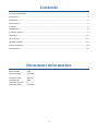
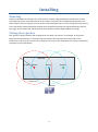
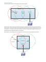
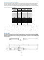
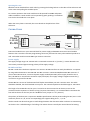
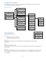
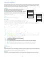
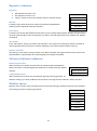
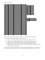
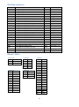
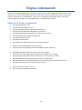
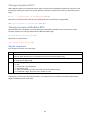
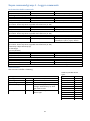
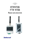
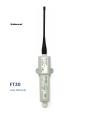
Nokeval FT20 User Manual Contents Document information ...................................................................................................................................... 2 Introduction ....................................................................................................................................................... 3 Trademarks ........................................................................................................................................................ 3 Manufacturer .................................................................................................................................................... 3 Installing ............................................................................................................................................................ 4 Maintenance...................................................................................................................................................... 8 Firmware settings .............................................................................................................................................. 9 Operation......................................................................................................................................................... 13 SCL protocol ..................................................................................................................................................... 14 Modbus protocol ............................................................................................................................................. 15 Nopsa commands ............................................................................................................................................ 18 Specifications ................................................................................................................................................... 22 Document information Device Scope: Device Versions: FT20 1.0 to 1.0 Document Type: Document ID: Document Version: Document Date: manual 2873 8 3.11.2011 2 Introduction FT20 is a radio data receiver and repeater for Nokeval MTR, FTR and KMR series wireless transmitters. Type FT20-RTC433-RECEIVER means the device is pre-set as receiver only. Type FT20-RTC433-REPEATER means the device is pre-set as repeater and is supplied with a power supply. FT20 receives and buffers the data packets that wireless transmitters have sent. It can also relay the data packets so that large areas can be covered using only one receiver. It automatically recognizes the types of the transmitters, so different kinds of transmitters can be used simultaneously. Transmitters can also have different transmission intervals. FT20 uses license-free 433.92 MHz frequency band (ISM) so it can be freely used, for example, almost in whole Europe. FT20 is housed in a watertight (IP 66) and impact resistant plastic enclosure. The joint between the two modules is sealed with two rubber O-rings. The receiver is connected to a computer using RS-485 bus and it requires e.g. PromoLog data acquisition application that reads the data from the device. Nokeval SCL or Modbus RTU protocol is used for data transmission between the receiver and the computer. Multiple receivers can be connected in parallel to an RS-485 bus to increase the coverage area. FT20 has one diagnostic LED and it requires 8..30 VDC power supply. Trademarks This device uses the FreeRTOS real-time operating system version 6.0.5. The source code of the RTOS is available on request – contact [email protected]. Manufacturer Nokeval Oy Yrittäjäkatu 12 FI-37100 Nokia Finland Tel +358 3 3424800 (Mo-Fr 8:30-16:00 EET) WWW http://www.nokeval.com/ email [email protected], [email protected] 3 Installing Mounting The best installation environment for a radio receiver is above a big grounded horizontal metal surface surrounded by as few as possible vertical metal surfaces. Antenna is to be installed perpendicular to the metal surface. The best range for the transmitter is achieved when there is a line-of-sight from the receiver to the transmitter. Walls and objects between the transmitters attenuate the signal and thereby shorten the range. On the other hand, metal surfaces cause reflections which might lengthen the range. Placing the repeaters The repeater must be placed in the coverage area of at least one receiver. For example, in the picture below the whole warehouse is covered using two repeaters that are placed near both ends of the warehouse. In this way the receiver that is placed in the center of the warehouse can receive transmissions anywhere from the warehouse. Warehouse 50..200 m Repeater Receiver Coverage area RS-485 4 Repeater Using two repeaters The picture below shows how two repeaters can be daisy chained. Warehouse 50..200 m Repeater Repeater Receiver Coverage area RS-485 The downside of daisy chaining is that now both repeaters relay also the data that they receive from the other repeater. This increases radio traffic and therefore decreases the maximum allowed number of radio transmitters in a coverage area. See the transmitter’s manual or example table on page 6 how the use of repeaters affects the maximum number of transmitters. Both repeaters can be placed in the coverage area of one receiver like in the example picture below. 50..200 m Warehouse Coverage area Repeater Repeater Receiver RS-485 5 The maximum number of transmitters The maximum number of radio transmitters in a coverage area is limited by radio standards. The use of repeaters reduces the maximum number of transmitters because repeaters use the same frequency channel as transmitters. The following example table shows the allowed maximum number of Nokeval radio transmitters in a coverage area. Receiver and Receiver and 1 repeater 1 repeater Transmission Receiver Interval (s) Maximum number of transmitters 5 22 11 7 10 43 22 14 20 87 43* 29 30 130 65 43 40 174 87 58 50 217 109 72 60 261 130 87 70 304 152 101 80 348 174 116 90 391 196 130 120 522 261 174 240 1043 522 348 For example, if you have transmission interval of 20 seconds and one repeater, the maximum number of transmitters is 43*. Note: ID filter can be used to reduce the radio traffic caused by the repeaters. Using ID filter, only the desired transmitter data packets is repeated (see the section "Firmware settings" sections Repeater/ID filter and Channels/Repeater). Enclosure FT20 consists of a radio transceiver module (FT20-RTC433) and a processor/serial module (FT20-RS485). Before use, please make sure that the modules are pushed together all the way so that the locking latches snap into position. 6 Opening the case Modules can be detached from each other by pressing the locking latches on the sides of the enclosure and at the same time pulling the modules apart. For receiver operation the serial module must be opened for RS485 and power cables installation. Serial module can be opened by gently pushing a screwdriver into the slot that holds the cover plate. When the cover plate is removed, the circuit board can be pulled out of the enclosure. Connections + - D1 D0 Power 8...30 VDC RS-485 1 2 3 4 POL Diag. LED Jumpers Repeater Default RS485 settings RS485 AC term. Transmit. LED FT20 serial module has a 4-pin terminal block for power supply and RS-485 connection. Serial module features also a round 3.5 mm POL programming connector jack found on many other Nokeval products as well. FT20 radio module contains BNC type antenna connector. Power supply The supply voltage range is 8...30 VDC and is connected to terminals 1 (+) and 2 (-). Power demand is 50 mA. FT20 is protected against wrong polarity of the supply voltage. RS-485 serial bus RS-485 is used when the device operates as a receiver. RS-485 interface can easily be added to a computer by using Nokeval DCS770 or DC771B USB - RS-485 converter or RCS770 USB/RS-232-RS-485 converter. If you use DC771B converter, no external power supply needed (DC771B's power supply should be set to 10V). RS-485 bus is connected to terminals 3 (D1) and 4 (D0). The supply voltage's negative terminal 2 (-) can also use as ground for RS-485. The RS-485 bus consists of a bidirectional half-duplex twisted data pair and a common wire. The cable should be shielded, the shield earthed at one point. The nominal impedance should be approx. 100-120 Ω. The length of an RS-485 bus can be up to 1 km and it can be connected to 32 devices, more can be connected via bus repeaters. If the bus is long (say more than 100 m), it is recommended to terminate the first and last device on the bus (set the ”RS485 AC term” jumper to ”on” position). The polarity of the data pair is important. Modbus specifications call the positive idling line D1, but it is also commonly known as +, B, and A. Correspondingly the negative idling line is -, A, or B. The bus needs one device that gives a small voltage between the data wires when no device is transmitting on the bus. This is called biasing or fail-safing. The master device is usually the natural choice for biasing. 7 POL connector The POL connector is convenient for configuring when the device operates as a repeater. This connector can be used when the modules are disconnected from each other. Note that when the POL plug is connected the RS-485 bus is disabled. Two types of programming cables are available: POL-RS232 for the RS-232 port of the computer. DCS772 for the USB port of the computer (recommended). Antenna Antenna is connected to the transceiver modules’s BNC connector. Antenna is first pushed into the BNC connector by aligning it with two guide posts after which it is turned 90 degrees clockwise. Antenna can be removed by turning it counterclockwise after which the antenna can be pulled off. Jumpers FT20 has three jumpers in the serial module: ”RS485 AC term” RS-485 termination jumper, default serial settings jumper and jumper which turns repeater on or off (if enabled in firmware settings). If the device is the last device on the RS485 bus and the bus is long (say more than 100 m), it is recommended to set the ”RS485 AC term” jumper to ”on” position. When this jumper is set, AC termination is used which means that 1 nF capacitor and 110 ohm resistor are connected in series between the bus wires. Maintenance Cleaning The plastic parts can be cleaned with a soft cloth and soap water. The cloth must be damp but not wet. Cleaning with isopropyl alcohol is also allowed. 8 Firmware settings Repeater mode User does not normally need to setup the device. By default, the device type FT20-RTC433-REPEATER is setup as repeater (repeater jumper is on) and it repeats all the received data packets. In some special cases, for example, when there is lot of transmitters, ID filtering may be needed. Receiver mode If you use PromoLog data acquisition software, then there is generally no need to configure the device. Just check that the repeater jumper is off because the repeater mode is not needed and thus prevent the extra radio traffic. Mekuwin MekuWin can be used to change settings on various Nokeval products. It has a unique feature: it loads the structure and the contents of the configuration menu from the target device, so the same MekuWin version can be used with past and forthcoming products. There is no need to update this software every time a new product or product version is released. You can download Mekuwin from Nokevals web site for free. Mekuwin has its own instruction manual. It is also possible to change the configuration settings remotely by writing to the appropriate Modbus Holding registers. With a POL programming cable The communications parameters for POL are always: Protocol Baud Parity Address SCL 9600 8N1 0 Over the RS-485 serial bus The Mekuwin communications parameters must match the selections made in the device (Serial menu). Resetting RS-485 serial communication settings In case RS-485 serial settings are for some reason not known, they can be temporarily set to defaults by the “default RS485 settings” jumper (shown in the figure on page 7) when the device is powered up. Default communication parameter settings: Protocol Baud Parity Address SCL 9600 8N1 0 9 Configuration settings The configuration settings are arranged as a hierarchical tree: The Conf menu has submenus, and these contain settings and possibly more submenus, etc. Menu of the FT20: Serial Protocol Baud rate Bits Conf Serial Address Channels Channels Repeater Timeout[min] Count Repeater Advanced Options Repeater Ch1 Ch1 ID filter Ch2 ID Extra bytes Ch3 Value Max jumps Ch4 Reading Replace with RSL Ch5 Info Ch6 Repeater Advanced Options Ch7 Weak repeater filter ... Compatibility mode Ch32 Serial Serial submenu Protocol Serial communication settings. Baud rate Protocol SCL: Nokeval SCL protocol. Default. Modbus RTU: Modbus RTU protocol Bits Address Baud rate Baud rate selection: 300, 600, 1200, 2400, 4800, 9600, 19200, 38400, 57600, 115200, 230400. Default 9600. Bits Bit selection: 8N1, 8N2, 8E1, 8O1. Note! SCL protocol uses always 8N1 (this item does not appear when the protocol is SCL). Modbus RTU uses commonly 8E1. Address Serial communications address selection. Since several devices can be attached to a bus, each device needs to be configured to a different Address. Valid SCL-addresses are 0...123. Valid Modbus RTU-addresses are 1...247. Default 0. 10 Channels submenu Up to 32 channels can be set up in the radio receiver. These channels can be set up to contain any data received from the radio transmitters. The values of these channels can then be queried over the serial interface. This menu contains settings for configuring these channels. Timeout The number of how many minutes have to pass since last reception until it is determined that the device is not transmitting anymore and its value is set to NaN (Not a Number). For example if Timeout = 10 min then channel value is set to NaN when more than 10 minutes but less than 11 minutes have passed since last reception. Count Sets how many channels are used (0...32). Channels Timeout[min] Count Ch1 Ch1 ... ID Ch32 Value Reading Info Ch1 ... Ch32 32 MTR series transmitters (for example MTR260 and FT10) can Repeater be defined to act as certain channels. For example, when the device receives ”MEA CH 1?” command it sends latest received data from the transmitter that has been assigned to channel one. To assign a device to channel one, set the transmitter's ID to Ch1 ID value. Other channels can be assigned in the same way. ID Identification (ID) number of the transmitter (1…65535). Value Defines where the contents (reading) of the channel comes from: Input: Measurement result from the wireless transmitter. TcB, TcC, TcD, TcE, TcG, TcJ, TcK, TcL, TcN, TcR, TcS or, TcT: Used thermocouple linearization if transmitter in question can measure temperature with thermocouples but cannot perform the necessary thermocouple linearization by itself. Batt: Battery voltage of the transmitter. CJ: Cold junction temperature of the transmitter. RSL: Received signal level. Interval: Tells how many seconds between successive receptions from the transmitter. Age: Tells how many seconds have passed since last reception from the transmitter. Jumps: The number of repeaters the data from the transmitter has passed through. Reading Channel reading. Info Shows information on the corresponding transmitter. Signal level, battery voltage, seconds elapsed from the last reception, transmitter type and number of repetitions. Repeater If “ID filter” is checked in Repeater submenu, only those IDs will be repeated that have this setting on. 11 Repeater submenu Repeater Off: Repeater function is off. On: Repeater function is on. Jumper: Jumper controls the repeater function. Default setting. ID filter If checked, only those IDs that are checked in Channels/ChX/Repeater submenu will be repeated. Default unchecked. Repeater Repeater ID filter Extra bytes Max jumps Replace with RSL Extra bytes If checked, the device adds additional information to the repeated data packets: Number of hops and the received signal strength. Group of repeaters can deliver received signal level of the weakest link. Default unchecked. Max jumps If the “Extra bytes” setting is checked in all repeaters in the system, this setting can limit the number of repeats (jumps) and thus prevent an endless repeating cycle of data packets. Default value 15. Replace with RSL This setting is reserved for testing purposes only. When checked, the original measurement value of the repeated data is replaced with the received signal level. Default unchecked. Advanced Options submenu Weak repeater filter When checked, the repeater function will not repeat already repeated data packets that have a received signal level weaker than already received. Default checked. Advanced Options Weak repeater filter Compatibility mode Compatibility mode When checked, the receiver uses an alternate signal processing algorithm. Try different setting if you have problems with reception in low signal level conditions. Default checked. Monitor menu Monitor menu contains some information that can be useful during installation and which may facilitate monitoring the system's operating condition. Mon Uptime[h] LastID LastType Last RSL[dBm] RSL[dBm] Switches 12 Operation FT20 has one diagnostic LED that shines through the case of the device. This LED blinks slowly when the unit is operational but not receiving any radio data packets at the moment, and blinks rapidly when radio data packets are being received. Receiver operation Promolog data acquisition software PromoLog is a modular data acquisition software allowing you to design customized data collection and monitoring applications matching your needs. Applications are created by dragging suitable modules from library onto the screen. Both wireless and wired transmitters are supported practically without channel limits. You can also place photos or drawings on the background. Serial commands In case PromoLog data acquisition software is not used for reading data from the device, then following protocols can be used to read data from the device: Nokeval SCL protocol (page 14). o Reading with SCL commands. o Reading with Nopsa commands over SCL protocol (page 18). Modbus RTU protocol (page 15). o Reading Modbus registers. o Reading with Nopsa commands over Modbus protocol (page 18). 13 SCL protocol A full specification of the Nokeval SCL protocol can be downloaded from Nokeval WWW site. In short, the command frame consists of an address byte (bus address+128), a human-readable command, an ETX character (ASCII 3) and an XOR checksum of all bytes excluding the address byte. A normal response consists of an ACK (ASCII 6), a human-readable response, an ETX and an XOR checksum of all the bytes including the ACK. An error response is similar, but the ACK is replaced by a NAK (ASCII 21). Nokeval SCL always uses 8N1 parity. SCL Commands This device supports the following SCL commands: TYPE ? Returns the model name and software version of the device. SN ? Returns the device's serial number, for example ”A123456”. MEA CH <ch> ? Returns the last received value from the channel <ch>. The response may contain digits 0-9, minus sign, and a decimal point. The scientific representation 1.00E-3 is not used. If the channels result is NaN (Not A Number), device returns ------. MEA SCAN <first> <last> Returns the last received values of channels <first> to <last> separated with a space. E.g. MEA SCAN 1 3 will return the values of channels 1, 2, and 3. An example response: 25.6 29.1 0. If the channels result is NaN (Not A Number), device returns -----DBG 1 ? Returns the oldest unread data packet from the ring buffer. DBR 1 <xx> ? Returns a data packet from the ring buffer at location <xx>. DBX Clears the ring buffer (marks all data packets as read). DBS 1 ? Returns the size of the ring buffer. N <hexadecimal data> Encapsulating a Nopsa command in SCL. The Nopsa command is converted to hexadecimal characters without spaces. E.g. querying the serial number: N 0102. The device responds with hexadecimal characters carrying a Nopsa response. See section “Nopsa commands”. MN <hexadecimal data> A legacy command for encapsulating Meku configuration commands in SCL protocol. Using Nopsa is recommended. 14 Modbus protocol Supported Modbus RTU commands: • 3 Read Holding Registers: Read settings. • 4 Read Input Registers: Read result values. • 6 Write Single Register: Change settings. • 16 Write Multiple registers: Change multiple settings at once. • 17 Report Slave ID: Device type information. • 109 Meku: This is used by Mekuwin configuration software. • 110 Nopsa: This is used to transport Nopsa protocol on Modbus. Command 17 returns 0x11 <byte count> 0x00 0xFF, followed by for example “FT20 V1.0 A123456” Maximum Modbus packet length is 240 bytes. This affects the maximum possible register count that can be accessed simultaneously with commands 3, 4 and 16. When settings are changed, the device will save the settings instantly into the configuration EEPROM memory. If serial settings are changed, new settings will take effect only after cycling the device power, it works this way so that all serial settings can be done at once without breaking the serial connection. Data types: • BOOL: On/off value. 0=off, 1=on, in lower (right hand side) byte. • BYTE: 8-bit value. Only lower (right hand side) byte used. • WORD: 16-bit value. • ENUM: List of alternatives. • FLOAT: 32-bit float IEEE 754. Least significant word first, inside word most significant byte first. • STRINGZ: Zero terminated string. In one Modbus register data is presented as most significant byte first. 15 Input registers 0..1 2..3 … 62..63 Ch1\Reading FLOAT (LSW, MSB) Ch2\Reading FLOAT (LSW, MSB) … Ch32\Reading FLOAT (LSW, MSB) 200..201 202..203 … 262..263 Ch1\Reading FLOAT (MSW, MSB) Signed Ch2\Reading FLOAT (MSW, MSB) Signed … Ch32\Reading FLOAT (MSW, MSB) Signed 400..401 402..403 … 462..463 Ch1\Reading FLOAT (LSW, LSB) Ch2\Reading FLOAT (LSW, LSB) … Ch32\Reading FLOAT (LSW, LSB) Signed Signed 600..601 602..603 … 662..663 Ch1\Reading FLOAT (MSW, LSB) Ch2\Reading FLOAT (MSW, LSB) … Ch32\Reading FLOAT (MSW, LSB) Signed Signed 1000 1001 … 1031 Ch1\Reading WORD Ch2\Reading WORD … Ch32\Reading WORD Signed Signed 2000 2001 2002 2003 2004 … Ch1\ID Ch1\Type Ch1\Battery Ch1\Signal Ch1\Flags Unsigned See Table E1 Unsigned Unsigned See Table E2 WORD ENUM WORD WORD WORD Signed Signed Signed Signed Table E1 Value Type 0 MTR260 1 MTR262 2 MTR264 3 MTR265 4 MTR165 5 FTR860 6 CSR260 7 Unknown Table E2 Bits Bits 0..6 Age counter [min] 7 Data changed Signed Signed Measured values are available in 4 different word/byte order formats in registers below 1000. All floats are 32-bit floating point numbers according to IEEE 754. In registers 0...63: Least significant word first, inside word most significant byte first. In registers 200…263: Most significant word first, inside word most significant byte first. In registers 400...463: Least significant word first, inside word least significant byte first. In registers 600...663: Most significant word first, inside word least significant byte first. In registers 1000...1031 results of channels are presented using fixed point notation with 1 decimal. In example integer 150 means 15.0. Note! In case the reading is too old (older than the timeout parameter configured in the menu specifies) or there is no reading for a channel then float value is Quiet NaN ( 0x7FC00000 ) and word value is 0x7FFF. 16 Holding registers Address 2000 2001 2002 2003 2004 2005 2006 2007 2008...2009 2010...2025 2026 2027 2028 2029...2030 2031...2046 2047 … 2678 2679 2680 2681 2682 2683 2684 Name Conf\Serial\Protocol Conf\Serial\Baud rate Conf\Serial\Bits Conf\Serial\Address Conf\Channels\Timeout[min] Conf\Channels\Count Conf\Channels\Ch1\ID Conf\Channels\Ch1\Value Conf\Channels\Ch1\Reading Conf\Channels\Ch1\Info Conf\Channels\Ch1\Repeater Conf\Channels\Ch2\ID Conf\Channels\Ch2\Value Conf\Channels\Ch2\Reading Conf\Channels\Ch2\Info Conf\Channels\Ch2\Repeater Type ENUM ENUM ENUM BYTE BYTE BYTE WORD ENUM FLOAT STRINGZ BOOL WORD ENUM FLOAT STRINGZ BOOL Values See table E3 See table E4 See table E5 Unsigned 0...247 Unsigned 1...255 Unsigned 0...32 Unsigned See table E6 Signed Len=32 Conf\Repeater\Repeater Conf\Repeater\ID filter Conf\Repeater\Extra bytes Conf\Repeater\Max jumps Conf\Repeater\Replace with RSL Conf\Advanced Options\Weak repeater filter Conf\Advanced Options\Compatibility mode ENUM BOOL BOOL BYTE BOOL BOOL BOOL See table E7 Enum values Table E3 Value Protocol 0 SCL 1 ModbusRTU Table E5 Value Bits 0 8N1 1 8N2 2 8E1 3 8O1 Table E4 Value Baud rate 0 300 1 600 2 1200 3 2400 4 4800 5 9600 6 19200 7 38400 8 57600 9 115200 10 230400 Table E7 Value Repeater 0 Off 1 On 2 Jumper Table E6 Value Value 0 Input 1 TcB 2 TcC 3 TcD 4 TcE 5 TcG 6 TcJ 7 TcK 8 TcL 9 TcN 10 TcR 11 TcS 12 TcT 13 Batt 14 CJ 15 RSL 16 Interval 17 Age 18 Jumps 17 Unsigned See table E6 Signed Len=32 Unsigned 1...15 Nopsa commands Nopsa is a command language which enables measurement data and configuration data transfer. Nopsa can be used to transfer data between devices or from host to device. Nopsa needs some transfer layer protocol, which takes care of addresses, transfer error management and packet length. This device supports Nopsa commands over either Nokeval SCL or Modbus RTU protocols. Supported Nopsa commands 1/0 (Type) Read device type 1/1 (Version) Read device version 1/2 (Serial number) Read serial number of the device 1/3 (Description) Read short description of the device 1/4 (Command set) Read command set number for the device 1/5 (Serial buffer size) Read serial buffer size 1/7 (Radio ID) Read radio ID 1/16 (Reset) Reset device 1/32 (Meku) Pass Meku configuration commands to device 2/0 (Out value request) Read channel reading 2/1 (Out resource request) Read channel metadata (name, data type) 4/0 (Buffer info) Read buffer size and current write position 4/1 (Find oldest from buffer) Move read position to oldest entry in buffer 4/2 (Find newest from buffer) Move read position to newest entry in buffer 4/3 (Read buffer with index) Read specific data entry from buffer 4/4 (Read next from buffer) Read data entry from buffer and move read position to next 4/5 (Reread last) Returns last read operation contents 7/10 (Carrier) Turn carrier on or off. 7/11 (Test packet) Send RF test packet 18 Transport protocol SCL When Nopsa packets are transported on SCL data is converted to hexadecimal notation (0-9 and A-F). One Nopsa byte will become 2 bytes. No spaces between characters. Packet starts with SCL command N and a space. ID ’N’ ’ ’ Nopsa-packet in hexadecimal ETX BCC Response is transferred also same way in hexadecimal, but N command is not appended. ACK Nopsa-response in hexadecimal ETX BCC Transport protocol Modbus RTU Command function 110 (0x6E) is reserved for Nopsa commands in Modbus free command area. After function code there is one byte which informs Nopsa packet length. ID 0x6E Length Nopsa-packet CRC Response is in same format. 0x6E Length Nopsa-packet CRC Nopsa response Each response contains first status byte. Bit .7 .6 .2-.0 Description Internal error. Device has detected some internal malfunction. In example flash memory don’t respond. More detailed error information need to be request by Meku Diag. External error. Device has detected some external error. More detailed error information need to be requested by Meku Diag. Command progress: * 0 = OK * 1 = Command is not supported * 2 = Parameter error * 3 = Device is unable to process the command at the moment (busy) * 4 = Command is legal, but some error caused it to fail If response is not OK, then the response data is not response for the command. Command specific data begins immediately after status byte. 19 Nopsa command group 1 – Basic commands Command 1/0 (Type) 0x01 | 0x00 string: Device type as string -> FT20 Response status | string Command 1/1 (Version) 0x01 | 0x01 string: Device version as string -> V1.0 Response status | string Command 1/2 (Serial number) 0x01 | 0x02 string: Device serial number as string -> A123456 Response status | string Command Response 1/3 (Description) 0x01 | 0x03 status | string string: Device description as string -> “Wireless data receiver and repeater” Command Response 1/4 (Command set) 0x01 | 0x04 status | set*4 *(*4 means 4 bytes) Set: Informs which Nopsa command set device implements. Command sets are described in another document. Command 1/5 (Serial buffer size) 0x01 | 0x05 size: Informs serial buffer size of the device Response status | size Command Response 1/16 (Reset) 0x01 | 0x10 No response Device resets immediately after command and don’t response for it. Command 1/32 (Meku) 0x01 | 0x20 | Meku command Command used by Mekuwin configuration software 1/7 (Radio ID) id: Device radio ID. Command 0x01 | 0x07 Response status | Meku response Response status | id*2 Nopsa command group 2 – Data commands Command Response 2/0 (value request) 0x02 | 0x00 | number status | type | data*4 number: Channel number 0..31, type: 4 (FLOAT), data: float IEEE754 Command Response 2/1 (resource request) 0x02 | 0x01 | number status | types | flags | name*n number: Channel number 0..31, types: 4 (FLOAT), flags:0, name: Ch1..Ch32 20 Nopsa command group 4 – Logger commands Real-time data buffer commands Command Response 4/0 (Buffer info) 0x04 | 0x00 status | size*2 | write position*2 size: Ring buffer size (96), write position: position next to be written Command 4/1 (Find oldest) 0x04 | 0x01 read position: position where is oldest data, lap counter: how many times ring buffer has rolled over (0..255) Response status | read position*2 | lap counter Command 4/2 (Find newest) 0x04 | 0x02 read position: position where is newest data, lap counter: how many times ring buffer has rolled over (0..255) Response status | read position*2 | lap counter 4/3 (Read buffer with index) Command 0x04 | 0x03 | index*2 Response status | index*2 | lap counter | timestamp*4 | id*2 | type | data*n index: buffer read position lap counter: how many times ring buffer has rolled over (0..255) timestamp: 4-byte timestamp (0) id: data origin type: 32 (STRUCT) Command 4/4 (Read next) 0x04 | 0x04 In case of no new data return only status byte Response As in command 4/3 Command Response 4/5 (Reread last) 0x04 | 0x05 As in command 4/3 Return data which was read last. This has its uses when serial communication error happens. Data structure Data structure in buffer is following Data type STRUCT Struct type Device type Signal strength Bytes + battery 0 1 byte 1 byte 1 byte Data bytes 0-7 bytes Raw radio data packet Subtract 127 to get result in dBm. 3 msb data bytes, 5 lsb battery voltage. Divide battery by 10 to get result in volts. Information is dependent on device type. 21 Table for possible device types Type Value MTR260 0 MTR262/FTR262 2 MTR264 4 MTR265 5 MTR165 6 FTR860 7 CSR264S 8 CSR264L 9 CSR264A 10 CSR260 11 KMR260 12 Specifications Radio Antenna Connector Antenna Max input power Frequency band Ring buffer memory LEDs 50 Ω BNC female connector Whip antenna +10 dBm license free 433.92MHz ERC/REC 70-03 sub channel f (sub channel e in older specs) 96 latest transmissions Internal LED Glows through the case Settings Connection Protocol Software RS-485 serial connection Connector Protocol Baud rates Modbus parity 4-pin terminal block combined with power supply, terminal 3 D1, terminal 4 D0. Maximum cable length is 1000 m Nokeval SCL, Modbus RTU, Nopsa 300, 600, 1200, 2400, 4800, 9600, 19200, 38400, 57600, 115200, 230400 bits/s 8N1, 8N2, 8E1, 8O1 Voltage Current Operating temperature Storage temperature Humidity Protection class -30…+60 °C -40…+70 °C max 90 %RH non-condensing IP66 Dimensions Length Width Height Weight 379.6 mm, inc. antenna 60.2 mm 32.5 mm 123 g Regulations EMC immunity EMC emissions 4-pin terminal block combined with RS-485, terminal 1 +, terminal 2 -. 8…30 VDC 50 mA R&TTE directive EN 300 220 class 3 EN 300 489 EN 300 339 External Power supply for FT20-RTC433-REPEATER Input voltage Input frequency Max. input current Insulation class AC power plug Enclosure RS-485 or POL Nokeval SCL-Meku 1 Mekuwin for Windows Environmental Power supply Connector Transmission activity. Blinks slowly: Ready for operation Blinks rapidly: Reception activity 100…250 VAC 50…60 Hz 150 mA Class II Europlug The power supply is only designed for indoor use and should not come into contact with water or dust. 22 EN 61326 EN 61326 class B