1
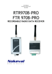
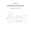
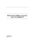
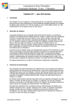
User manual
22.1.2007
V2.0
7470
Serial to analog converter
INTRODUCTION
7470 is a serial-bus controlled analog output unit. It
provides four mA or V outputs, that can be
controlled via an RS-232 or RS-485 bus. As a
slave, it supports Nokeval SCL, Modbus RTU, and
Ascii protocols. Alternatively, it can function as a
SCL Master querying other devices.
Analog output ranges include 0-20mA, 4-20mA, 05V, and 0-10V.
7470 needs 24 VDC supply voltage. The analog
outputs are not galvanically isolated from the
power supply or each other. They share the
common negative wire. However the serial bus is
galvanically isolated.
How to use this manual
The chapter General shows how to mount and
connect this device. It also tells how to access the
configuration settings. The settings itself are
described in chapter Configuration menu. Each of
the available serial modes are described in the
chapters of their own.
Table of contents
Introduction.........................................................................................................................................................2
General...............................................................................................................................................................3
Configuration menu............................................................................................................................................5
SCL protocol.......................................................................................................................................................7
Modbus protocol.................................................................................................................................................8
Ascii mode........................................................................................................................................................10
SCL Master.......................................................................................................................................................12
Metso Hart........................................................................................................................................................14
Nopsa................................................................................................................................................................15
Specifications....................................................................................................................................................16
Manufacturer
Tel +358 3 3424800
Fax +358 3 3422066
WWW: www.nokeval.com
Nokeval Oy
Yrittäjäkatu 12
FIN-37100 Nokia
Finland
2
GENERAL
Mounting
This transmitter is intended to be mounted on a 35
mm DIN rail.
Connections
RS-485
RS-232
Supply voltage
24 VDC
D1 (A+)
D0 (B-)
Com
RX
Com
TX
+
1
2
3
4
5
6
7
8
9
10
11
12
13
+ mA
14
- Com
15
+V
16
+ mA
17
18
- Com
+V
19
+ mA
20
21
- Com
+V
22
+ mA
23
- Com
24
+V
Output 1 (Ch1)
Output 2 (Ch2)
Output 3 (Ch3)
Output 4 (Ch4)
The green connector blocks are detachable to make connecting easier. They accept up to 2.5mm2 wires.
Jumpers
J1
J1
J2
Jumper J1 should be normally open. It is closed
when the 7470 baud rate is not known, to force
9600 baud.
J2
Baud rate configured
on menu settings
Baudrate fixed to
9600baud
RS-485 Non-terminated
RS-485 Terminated
To access the jumpers, the enclosure has to be
opened. Detach the converter from the DIN rail and
insert a small flat-bladed screwdriver between the
top (grey) and bottom (black) parts of the
enclosure at each side and pull the top part off.
Jumper J2 engages the RS-485 termination. It
should be closed if this device is the last on the
bus, otherwise open.
3
Configuring
The 7470 can be configured with a PC or with a
hand-held programmer.
will also change the baud rate to 9600 and make
the 7470 to respond in any bus address. The plug
may be the plug of the programming cable, or any
3.5mm mono plug. When the plug is pulled off,
7470 will start using the protocol defined in the
configuration menu.
PC configuration
The configuration settings are accessed with a
software called MekuWin, available free of charge.
The configuration menu contents are described in
the chapter Configuration menu. How to use
MekuWin, see its manual.
The configuration settings may be accessed via
the RS-232 or RS-485 buses or via the 3.5mm
"POL" connector on the front panel.
Hand-held programmer
To use the POL connector, use a POL-RS232
cable or DCS772 USB-to-POL cable.
An alternative to the PC programming is to use a
hand-held programmer 6790. It is plugged to the
POL connector on the 7470 front panel. The menu
contents are described in the chapter Configuration
menu. How to use 6790, see its manual.
When the 7470 is configured for SCL (slave)
mode, it can be accessed via any port straight
away. This is the factory default.
In other modes than SCL (slave), a plug has to be
plugged to the POL connector on the front panel to
revert the 7470 to the SCL (slave) mode. The plug
Note: 6790 is not able to edit string type settings,
so it can not be used to edit the custom Ascii
parser configuration string.
4
CONFIGURATION MENU
Conf
Ch 1
Fetch
Ch 1
From
Groups
Ch 2
Range
1
Ch 3
Lo
2
Addr
Ch 4
Hi
3
First
Limit
4
Num
Ser
Ser
Mode
5
Baud
6
Parity
7
Addr
8
Parser
Put
String
Groups
Stime
1
DelayResp
Master
1
Master
Fetch
Put
1
2
From
3
Addr
4
First
5
Num
6
7
8
The menu is arranged hierarchically. The first level contains four submenus, one for each analog output, and
a serial communications submenu. Some of the settings are hidden when they are not used.
Ch submenus
Serial bus
OUT CH 1 100
Analog output
Internal channels
4-20mA
From=1
1 = 100
2 = 23.4
3 = -10.9
4 = 0.0
Each analog output is configured independently.
Range
The analog output range selection. Options are:
• 0-20mA
• 4-20mA
• 0-5V
• 0-10V
From
7470 contains 32 internal channels storing the
variable values sent via a serial bus. The channels
are numbered 1…32. The From setting is used to
select, which internal channel is used to control
this analog output.
Lo, Hi
Most often the values are sent to internal channels
1…4, and the first analog output channel follows
the first internal channel etc. However, some times
it may be useful to be able to have several analog
outputs following the same internal channel.
Analog output scaling. When the channel value
controlling the analog output corresponds to the Lo
setting, the output will give its low end signal (e.g.
5
4 mA if the range is 4-20mA). Likewise, the value
of Hi will give the high end signal.
points, e.g. the 4-20mA output will not go below
4 mA nor above 20 mA even if requested to.
Limit
If the safety timer expires, the output will go to
0 mA or 0 V despite of this setting.
Limits the analog output within the nominal range.
If enabled, the analog output will not exceed its end
Ser submenu
• In Modbus mode, legal values are 1…247.
• In HART mode, legal values are 0…127.
Mode
Serial bus protocol and mode.
• SCL (slave): Nokeval SCL protocol. 7470 may
be controlled using SCL commands, like OUT
CH and OUT SCAN. See chapter SCL protocol.
• Modbus: Modbus RTU protocol. 7470 may be
controlled using "write holding register" and
"write multiple registers" functions. All the
configuration settings are also accessible. See
chapter Modbus protocol.
• Ascii: 7470 accepts simple messages with no
proprietary protocol. The messages has to end
with cr, lf, or both. See chapter Ascii mode.
• SCL Master: 7470 acts as a serial bus master,
sending commands to the other devices on the
bus. Only one device should be a master on a
single bus. In this mode, 7470 can read serial
bus transmitters and Nokeval RTR970PRO
radio receiver without a PC or another master.
See chapter SCL Master.
• Metso HART: Hart-style protocol. See chapter
Metso HART.
Parser
Parser selection in Ascii mode. Options are:
• Classic: Non-configurable parser, equivalent to
7470 firmware versions 1.x.
• Custom: Configurable parser.
See chapter Ascii mode.
String
Parser configuration string in Ascii mode, when
Custom parser is selected. See chapter Ascii
mode.
Stime
Baud
Safety timer. Defines a safety time in seconds. If
some of the internal channels (see Ch\From on
page 5) is not refreshed within this time, the safety
timer will expire on that channel. An analog output
configured to follow that channel will then go low (0
V or mA). This works in every mode.
Baud rate 300…19200. All the devices on the bus
must have the same baud rate. Factory default is
9600.
The time can be selected from 1 to 60 seconds in
1 second steps. To disable the safety timers, set
value of 0 here.
Parity
DelayResp
Applicable for Modbus only. Options:
• 8N2
• 8E1 (recommended, factory default)
• 8O1
Applies to SCL (slave) mode only. When some
other device sends a SCL command to the 7470, it
will process the command and send a response as
soon as possible, but not earlier than 3.5
characters time from the end of the command. At
9600 baud, this minimum time corresponds to
3.6 ms.
Addr
Serial bus address of this device in SCL (slave),
Modbus, and Metso HART modes.
• In SCL mode, legal values are 0…123.
Inaddition to the selected address, 7470 will
always respond in address 126. When the POL
plug is inserted in the front panel, 7470 will
respond in any address.
If DelayResp is engaged, the interval between the
command and response is increased to 25 ms.
Master
The submenu used to configure how this device
acts as a SCL Master. See chapter SCL Master.
6
SCL PROTOCOL
A more detailed description of the Nokeval SCL
protocol can be downloaded from Nokeval WWW
site.
Acceptable characters are 0…9, minus, decimal
point, and leading or trailing spaces. A deliberately
invalid value (NaN) can be expressed as ----(several minus chars) to steer the analog output to
0 V or 0 mA to indicate something is wrong.
This unit understands the following SCL
commands:
OUT SCAN 1 4 10 20 30 40
TYPE ?
Sends several values to the internal channels 1 to
4 (give the first and the last). Maximum of 8 values
can be sent with one command; channels 1…9
can be accessed this way. The values are
separated with one or more spaces.
Returns the model name and software version
”7470 V2.0” without the quotation marks.
SN ?
Returns the serial number, e.g. ”A123456”.
MN xxxxx
OUT CH 1 100.0
Commands used by the Mekuwin configuration
software.
Sends a value of 100 to the internal channel 1.
Channels 1…9 are writable this way, although
normally up to four of them are used since 7470
has four analog outputs. About internal channels,
see the From setting on page 5.
N xxxxx
Nopsa commands encapsulated in SCL. See
chapter Nopsa.
7470 will return an empty response (ACK, ETX,
BCC).
7
MODBUS PROTOCOL
Commands
1001
Ch2
WORD
Signed
1002
Ch3
WORD
Signed
1003
Ch4
WORD
Signed
2000
Conf\Ch 1\From
BYTE
Unsigned 1...32
2001
Conf\Ch 1\Range
ENUM
See table E1
2002..2003 Conf\Ch 1\Lo
FLOAT
Signed
2004..2005 Conf\Ch 1\Hi
FLOAT
Signed
2006
Conf\Ch 1\Limit
BOOL
2007
Conf\Ch 2\From
BYTE
Unsigned 1...32
2008
Conf\Ch 2\Range
ENUM
See table E1
2009..2010 Conf\Ch 2\Lo
FLOAT
Signed
2011..2012 Conf\Ch 2\Hi
FLOAT
Signed
2013
Conf\Ch 2\Limit
BOOL
Maximum Modbus frame is 100 bytes.
2014
Conf\Ch 3\From
BYTE
Unsigned 1...32
Command 17 returns 0x11 <bytecount> 0x00
0xFF, and then ”7470 V2.0 A123456”, for example.
2015
Conf\Ch 3\Range
ENUM
See table E1
2016..2017 Conf\Ch 3\Lo
FLOAT
Signed
2018..2019 Conf\Ch 3\Hi
FLOAT
Signed
2020
Conf\Ch 3\Limit
BOOL
2021
Conf\Ch 4\From
BYTE
Unsigned 1...32
2022
Conf\Ch 4\Range
ENUM
See table E1
2023..2024 Conf\Ch 4\Lo
FLOAT
Signed
2025..2026 Conf\Ch 4\Hi
FLOAT
Signed
2027
Conf\Ch 4\Limit
BOOL
2028
Conf\Ser\Mode
ENUM
See table E2
2029
Conf\Ser\Baud
ENUM
See table E3
2030
Conf\Ser\Parity
ENUM
See table E4
2031
Conf\Ser\Addr
BYTE
Unsigned 0...127
2032
Conf\Ser\Parser
ENUM
See table E5
• 3 Read Holding Registers: read current
configuration
• 6 Write Single Register: change the
configuration and control the outputs
• 16 Write Multiple registers: change several
registers.
• 17 Report Slave ID: device type query.
• 109 Meku: Mekuwin uses this.
• 110 Nopsa: Nopsa commands.
Data types
• BOOL: Off/On setting. 0=off, 1=on on the lower
byte.
• BYTE: Single byte value. Only the lower (least
significant) byte used.
• WORD: 16-bit value. Most significant byte first.
• ENUM: List of options.
• FLOAT: 32-bit floating point IEEE 754. Least
significant word first. Inside the word, most
significant byte first.
Holding registers
The analog outputs can be controlled via registers
0..7 in IEEE-754 format, or alternatively via
registers 1000..1003 in regular 16-bit signed
integer format. These correspond to the internal
registers 1…4, see page 5.
The configuration settings are accessible in
register 2000 onwards. When the configuration is
changed, the changes are automatically stored in
the EEPROM. If the serial configuration is changed
via Modbus, the new settings do not affect until
powered down.
2033..2048 Conf\Ser\String
STRINGZ Len=32
2049
Conf\Ser\Stime
BYTE
2050
Conf\Ser\DelayResp
BOOL
2051
Conf\Ser\Master\Fetch\Groups BYTE
Unsigned 0...8
2052
Conf\Ser\Master\Fetch\1\Addr BYTE
Unsigned 0...255
2053
Conf\Ser\Master\Fetch\1\First BYTE
Unsigned 0...255
2054
Conf\Ser\Master\Fetch\1\Num BYTE
Unsigned 0...8
2055
Conf\Ser\Master\Fetch\2\Addr BYTE
Unsigned 0...255
2056
Conf\Ser\Master\Fetch\2\First BYTE
Unsigned 0...255
2057
Conf\Ser\Master\Fetch\2\Num BYTE
Unsigned 0...8
2058
Conf\Ser\Master\Fetch\3\Addr BYTE
Unsigned 0...255
2059
Conf\Ser\Master\Fetch\3\First BYTE
Unsigned 0...255
2060
Conf\Ser\Master\Fetch\3\Num BYTE
Unsigned 0...8
2061
Conf\Ser\Master\Fetch\4\Addr BYTE
Unsigned 0...255
2062
Conf\Ser\Master\Fetch\4\First BYTE
Unsigned 0...255
2063
Conf\Ser\Master\Fetch\4\Num BYTE
Unsigned 0...8
2064
Conf\Ser\Master\Fetch\5\Addr BYTE
Unsigned 0...255
2065
Conf\Ser\Master\Fetch\5\First BYTE
Unsigned 0...255
2066
Conf\Ser\Master\Fetch\5\Num BYTE
Unsigned 0...8
2067
Conf\Ser\Master\Fetch\6\Addr BYTE
Unsigned 0...255
2068
Conf\Ser\Master\Fetch\6\First BYTE
Unsigned 0...255
2069
Conf\Ser\Master\Fetch\6\Num BYTE
Unsigned 0...8
Unsigned 0...60
Register
Name
Type
Values
2070
Conf\Ser\Master\Fetch\7\Addr BYTE
Unsigned 0...255
0..1
Ch1
FLOAT
Signed
2071
Conf\Ser\Master\Fetch\7\First BYTE
Unsigned 0...255
2..3
Ch2
FLOAT
Signed
2072
Conf\Ser\Master\Fetch\7\Num BYTE
Unsigned 0...8
4..5
Ch3
FLOAT
Signed
2073
Conf\Ser\Master\Fetch\8\Addr BYTE
Unsigned 0...255
6..7
Ch4
FLOAT
Signed
2074
Conf\Ser\Master\Fetch\8\First BYTE
Unsigned 0...255
1000
Ch1
WORD
Signed
2075
Conf\Ser\Master\Fetch\8\Num BYTE
Unsigned 0...8
8
Table E1
2076
Conf\Ser\Master\Put\Groups
BYTE
Unsigned 0...8
2077
Conf\Ser\Master\Put\1\From
BYTE
Unsigned 1...32
2078
Conf\Ser\Master\Put\1\Addr
BYTE
Unsigned 0...255
2079
Conf\Ser\Master\Put\1\First
BYTE
Unsigned 0...255
2080
Conf\Ser\Master\Put\1\Num
BYTE
Unsigned 0...8
2081
Conf\Ser\Master\Put\2\From
BYTE
Unsigned 1...32
2082
Conf\Ser\Master\Put\2\Addr
BYTE
Unsigned 0...255
2083
Conf\Ser\Master\Put\2\First
BYTE
Unsigned 0...255
2084
Conf\Ser\Master\Put\2\Num
BYTE
Unsigned 0...8
Table E2
2085
Conf\Ser\Master\Put\3\From
BYTE
Unsigned 1...32
Value
Mode
2086
Conf\Ser\Master\Put\3\Addr
BYTE
Unsigned 0...255
2087
Conf\Ser\Master\Put\3\First
BYTE
Unsigned 0...255
0
SCL
2088
Conf\Ser\Master\Put\3\Num
BYTE
Unsigned 0...8
1
Modbus
2089
Conf\Ser\Master\Put\4\From
BYTE
Unsigned 1...32
2
Ascii
2090
Conf\Ser\Master\Put\4\Addr
BYTE
Unsigned 0...255
3
SCL Master
2091
Conf\Ser\Master\Put\4\First
BYTE
Unsigned 0...255
4
Metso Hart
2092
Conf\Ser\Master\Put\4\Num
BYTE
Unsigned 0...8
2093
Conf\Ser\Master\Put\5\From
BYTE
Unsigned 1...32
2094
Conf\Ser\Master\Put\5\Addr
BYTE
Unsigned 0...255
Value
Baud
2095
Conf\Ser\Master\Put\5\First
BYTE
Unsigned 0...255
0
300
2096
Conf\Ser\Master\Put\5\Num
BYTE
Unsigned 0...8
1
600
2097
Conf\Ser\Master\Put\6\From
BYTE
Unsigned 1...32
2
1200
2098
Conf\Ser\Master\Put\6\Addr
BYTE
Unsigned 0...255
3
2400
2099
Conf\Ser\Master\Put\6\First
BYTE
Unsigned 0...255
4
4800
2100
Conf\Ser\Master\Put\6\Num
BYTE
Unsigned 0...8
5
9600
2101
Conf\Ser\Master\Put\7\From
BYTE
Unsigned 1...32
6
19200
2102
Conf\Ser\Master\Put\7\Addr
BYTE
Unsigned 0...255
2103
Conf\Ser\Master\Put\7\First
BYTE
Unsigned 0...255
2104
Conf\Ser\Master\Put\7\Num
BYTE
Unsigned 0...8
2105
Conf\Ser\Master\Put\8\From
BYTE
Unsigned 1...32
2106
Conf\Ser\Master\Put\8\Addr
BYTE
Unsigned 0...255
2107
Conf\Ser\Master\Put\8\First
BYTE
Unsigned 0...255
2108
Conf\Ser\Master\Put\8\Num
BYTE
Unsigned 0...8
Value
Range
0
0-5V
1
0-10V
2
0-20mA
3
4-20mA
Table E3
Table E4
Value
Parity
0
8E1
1
8O1
2
8N2
Table E5
9
Value
Parser
0
Classic
1
Custom
ASCII MODE
Some weighs and weather transmitters are able to
output their readings in "Ascii", which means
human-readable data terminated by a cr or lf or
both. 7470 can receive and interpret most of this
kind messages. The transmitter has to be
configured to send its readings automatically –
7470 does not send query commands. 7470 will
not respond to Ascii packets.
Ascii packets can be sent with any terminal
software, e.g. HyperTerminal supplied with
Windows.
7470 expects 8 data bits and none parity (8N1), but
it discards the most significant bit. So it accepts
7E1 and 7O1 too but does not check the parity.
There is two parsers (algorithms that split the Ascii
message to fields and tries to find numerical
values there): "classic" and "custom".
Several 7470's can be parallel-connected to a RS485 bus to receive the Ascii messages. Each one
can be configured to handle a different part of the
message. Ascii mode does not use any addressing
nor checksum. However some addressing may be
realized with the custom parser, see below.
The classic parser does not allow any
configuration, but it is simple to use. It can be used
when the message contains values separated by
spaces, commas, semicolons, or tabulators. When
more control is needed, the custom parser gives
more freedom.
Classic parser
If the message is simple like this:
A=100.0, B=200.0, C=300kg, D=400m2, E=0
100.0,200.0,300.0,400.0<cr><lf>
Reading of 100.0 is read to the internal channel 1,
200.0 to channel 2, etc. m2 is ignored because one
numeric portion has been already found in that
comma-separated field.
7470 is able to handle it with the classic parser.
The fields may be separated with one comma, one
semicolon, one tabulator, or one or more spaces.
The maximum length of a message is 100
characters. Up to 32 fields may be read in to the
internal registers. The analog outputs can be
programmed to follow any of these internal
registers.
If there is non-numerical characters within the field,
7470 will ignore them until a numerical character
(0…9, minus, decimal point) is encountered. It will
then read in the figure until a field separator or any
other non-numerical character is encountered. So,
7470 is able to read this message:
Custom parser
If the message is not field-separated (delimited) by
a comma, space, semicolon, or tabulator, the
custom parser has to be used. Also, if the
transmitter sends several different types of packets
and only one of them is to be picked by a certain
7470, the custom parser is needed.
the message. The parser string consists of the
following parts:
The custom parser is configured with one string,
that contains instructions to 7470 how to handle
10
Part
Name
Description
*
Replace string
Any number of characters in the message will be ignored until a character
following the * is encountered in the message. E.g. *+ will ignore all
characters in the message until a + is found. The + will be ignored too.
?
Replace character One character will be ignored in the message. Several ?'s may be used
contiguously to ignore more characters.
%1
Pick
Picks a value to the internal channel 1 from the message. Will pick until a
character following the %1 is encountered in the message. E.g. %1, will
pick characters until a comma is found in the message. The comma will
be ignored then.
The channel number may be 1…32.
If the message contains non-numerical characters when the picking
starts, they will be ignored until a numerical character is encountered.
any other
Match
If the parser string contains other characters, the input string must have
equivalent characters, or the parser will exit. This feature can be used to
pick a certain type of packet, if the transmitter sends several different
packets.
When the parser exits, all the fields handled before exiting will be still
used.
Some examples will clarify things up.
*,*,%1,*,%2
Simple message
Ignoring characters
Consider a message like:
Consider a message:
10,20,30,40
W=10,H=22,L=50
To read this in, enter a parser string:
To ignore the letters and the equivalent signs, this
kind of parser string can be used:
%1,%2,%3,%4
??%1,??%2,??%3
(A comma-separated message could be handled
by the classic parser too.)
Or, if we want to be sure the letters and equivalent
signs are there and they are correct:
Custom delimiter
W=%1,H=%2,L=%3
If the message is separated (delimited) with e.g.
slashes like this:
Note: since 7470 is able to ignore the nonnumerical characters within the field, the message
can be read in with this simple parser string:
10/20/30/40<cr>
%1,%2,%3
The parser string that can interpret this to the four
first channels:
Addressing
%1/%2/%3/%4
If the transmitter sends several different types of
messages, and we want to accept only one of
them, we have to insert some "fixed" characters in
the beginning of the parser string.
If the delimiter is * or ? or %, it can't be mentioned
directly in the parser string, because those
characters have a special meaning to the parser.
They must be escaped by preceding them with a
%. A message separated by *'s would be handled
by a parser string like this:
An example: the transmitter sends alternately two
packets:
%1%*%2%*%3%*%4%*
0;10,20
1;30,40
Ignoring fields
If we want to accept the latter message only, we
enter the parser string this way:
If we have a message like:
1;%1,%2
10,20,30,40,50,60,70,80
Now, when the transmitter sends a message
0;10,20, the parser will reject it because it does not
match 1; mentioned in the parser string.
And want to read in the third and fifth field only,
enter the following parser string:
11
SCL MASTER
When there is no PC or any other device available
that could "master" the bus (i.e. command the bus
devices), one 7470 can be configured to act as a
master. It can read values from other devices on
the bus and redirect them to another devices. The
four analog outputs of the mastering 7470 are
available too.
There must always be exactly one master on the
bus. If there is no master at all, all the devices
listen only. If there is two or more masters, they will
collide.
The master does not have an address of its own.
Only the slaves use an address. Every slave must
be configured to a different address.
Fetching
Fetching means
querying values from
other devices on the
bus. These devices are
most often transmitters
measuring temperature,
voltage, current etc.
Also Nokeval
RTR970PRO radio
receiver can be read.
Conf
Ser
Fetch
Ch 1
Mode
Groups
Ch 2
Baud
1
Ch 3
Parity
2
Addr
Ch 4
Addr
3
First
Ser
Parser
4
Num
String
Master
5
Stime
Fetch
6
Put
7
The fetch operations
DelayResp
are configured in the
Master
menu
Ser\Master\Fetch.
There may be up to eight fetch groups. One group
corresponds to one serial command sent to
another bus device, and it may fetch up to eight
values.
The first setting, Groups, is used to select how
many fetch groups are needed.
Within each group, there is three settings. Addr
defines the serial bus address of the other device.
First tells from which channel to read on the other
device, and Num tells how many channels to read.
1
8
and group 2 fetches another 4, the values will be
placed in internal channels 1…4 and 5…8,
respectively.
The fetches may be configured freely. It is allowed
to do several fetches from the same bus device
(e.g. to fetch more than 8 values from a 16channel transmitter).
Every time a fetch is done successfully, the safety
timers of the updated internal channels are reset. If
some channel is not updated for a time specified in
Stime setting in the Ser submenu, that channel will
be considered expired. If an analog output is
following that channel, it will be pulled to 0 mA or 0
V.
The values fetched with group 1 are stored in the
internal channels 1 onwards. The values fetched
with group 2 are stored in the next "free" internal
channels etc. E.g. if group 1 fetches 4 channels
Putting
7470 is able to send or put the fetched values to
other devices on the bus. E.g. one 7470 can read
16 channels from a temperature transmitter and
then deploy the values to other 7470's to have
more than 4 analog outputs.
The first setting, Groups, is used to define how
many put groups are needed.
Within each group, there is four settings. Addr
defines the bus address of the other device. First
tells the first channel on the other device that the
valueas are sent to. Num tells how many values to
send.
Up to eight put groups may be defined. Each group
corresponds to one serial command sending up to
eight values to another device on the bus.
12
From defines the
Conf
Ser
internal channel of this
Ch 1
Mode
7470 that provides the
Ch 2
Baud
first value to be sent.
For example, if
Ch 3
Parity
configured as follows:
Ch 4
Addr
• From = 5
Ser
Parser
• Addr = 2
String
• First = 1
Stime
• Num = 4
DelayResp
The mastering 7470
will send values from
Master
its internal channels
5…8 to the channels 1…4 of the device on bus
address 2.
13
Put
Groups
1
1
2
From
3
Addr
4
First
Master
5
Num
Fetch
6
Put
7
8
If some internal channel has expired, dashes ----will be sent to indicate fault.
METSO HART
7470 can be controlled using the Hart protocol on RS-485 bus. Supported command set is minimalistic:
commands 0 and 206. As always with Hart, odd parity 8O1 is used.
7470 accepts only the long address, not the ”polling address”. Manufacturer ID is 47d or 2Fh (Valmet/Metso).
Device type byte is 01h. The two most significant bytes of the address are zero, and the least significant is
selectable on the configuration menu Ser\Addr, selectable 0..127d.
This device needs 2 preambles and sends 5.
Command 0: Read Unique Identifier
This command is useful to see the device exists on the bus.
Command 206: Controlling the outputs
The analog outputs are controlled with this command. After the command byte 206d or CEh comes one byte
indicating the number of data bytes. It may have the following values:
• 04h: control the output 1 only
• 08h: control the outputs 1..2
• 0Ch: control the outputs 1..3
• 10h: control the outputs 1..4
After that comes 32-bit floating point numbers in IEEE754 format the most significant or exponent byte first.
An example of the whole frame (in hexadecimal):
FF FF 82 AF 01 00 00 00
Pream D Mf T
ID
•
•
•
•
•
•
CE 10 40 00 00 00 40 C0 00 00 41 40 00 00 41 C0 00 00 B2
C Bc
Out1 = 2
Out2 = 4
Out3 = 8
Out4 = 16
LP
Mf = six lowest bits of manufacturer id, and most significant bit set for primary master
T = device type, always 01h
ID = 000000h + the address selected in the configuration
C = command
Bc = byte count
LP = longitudinal parity
The device will respond:
5xFF
Pream
86
D
AF
Mf
01
T
00
00
ID
00
CE
C
02
Bc
00
St1
00
St2
E4
LP
Possible errors are:
• Longitudinal parity error, status bytes 88 00 (in hexadecimal)
• Command not implemented 40 00
If the analog outputs are requested to go outside their range, they will go as far they can (Limit=off) or tho the
end of the range (Limit=on). No error is given.
14
NOPSA
Nopsa is a simple language intended for data interchange between devices. The data is transferred in binary
format, making it ideal for machine-to-machine communications. 7470 allows Nopsa commands to be sent
over SCL and Modbus protocols.
Nopsa is specified in a separate document, available on request.
This device supports the following Nopsa commands:
•
•
•
•
•
•
•
1/0: Type query, returns ”7470”.
1/1: Software version query, returns ”V2.0”.
1/2: Serial number query, returns ”A123456”.
1/3: Description query, returns ”Analog output unit”.
1/32: Meku configuration commands over Nopsa.
2/2: Control the analog outputs. Floating point format only supported.
2/3: Information on the outputs.
15
SPECIFICATIONS
Outputs
Channels
Isolation
4 outputs
Non-isolated from each other
and power. Common negative
wire.
Accuracy at 25°C
Operating range
Maximum load
Shortcircuit protect
mA output
0.1% of range
0..11.1V typ
5 kilo-ohms
yes (~15mA)
Response time
Ranges
Accuracy at 25°C
Operating range
Maximum load
0-20mA and 4-20mA
0.1% of range
0..22mA typ
600 ohms
Output reaction time 0-40ms
Output timing
4.7ms +reaction 0-40ms (67%
of end value)
12.5ms +reaction 0-40ms
(93% of end value)
150ms +reaction 0-40ms
(100% of end value)
V output:
Ranges
0-5V and 0-10V
Serial ports
Buses
Protocol
Baud rates
RS-232, RS-485
Nokeval SCL, Ascii, Modbus
RTU
300…19200 bauds
Response time
Termination
1-5 ms
Externally with a resistor or
internally with a jumper
50ppm/°C of range
12 bits (resolution 4096)
18…28VDC
30mA…110mA
Oper temperature
Protection
Attachment
Weight
0…55 °C
IP20
35 mm DIN rail
140g
General
Temp stablility
DA conversion
Supply voltage
Curr consumption
Dimensions
58
86
106
70
16