1
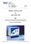
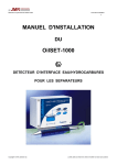
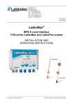
OY LABKOTEC AB
Labkotie 1
FIN-36240 KANGASALA
FINLAND
Tel.int. +358-3-2855 111
Fax int +358-3-2855 320
For software V1.3
7.4.1998 ArKa
D30013Be
Q
LABKO ME-3
Intelligent
Interface
Installation and
user manual
ME-3 Installation and User Manual
1
D30013Be
Q
The contents, descriptions and specifications within this manual is subject to
change without notice. Oy LABKOTEC Ab accepts no responsibility for any errors
that may appear in this manual.
ME-3 Installation and User Manual
2
D30013Be
Q
SOFTWARE REQUIREMENTS FOR PROBES
The LABKO 2000 level probes must have software version V3.2 or newer.
ELECTRICAL INSTALLATION
The cabling between the LABKO 2000 probes and the barrier units PS-12 is
described in the $LABK0-2000 SYSTEM DESCRIPTION#-manual.
The cabling of the PS-12's to ME-3 is described in the figure $ME-3 CONNECTION
TO PS-12#.
The digital outputs are used for alarm indication. The outputs are $open collector#type and each can drive 0.2A. The output drivers need a power supply: 15...30V
DC. The current consumption is < 100 mA. The same power supply is also used for
the loads. See figure $ME-3 OPTIONAL I/O".
CONFIGURING THE ME-3
The ME-3 can be configured by two ways: a simple configuration by ME-3
keyboard or a full configuration with ME3 configuration software (included in
delivery).
Simple configuration
A simple configuration can be carried out by ME-3 keyboard using the following
options in the Settings menu (described later in this manual): Setting number of
probes, Setting the alarm limits and Setting date and time. This configuration
method requires that the probes are numbered 01, 02, ... and that they are
connected to current loop 1. The name of the procuct to be shown in the display is
left blank.
Full configuration
The ME3 configuration software is used to make a full configuration to the ME-3.
The software runs on a normal DOS PC and communicates with ME-3 through
serial port.
The serial port (1 or 2) of the PC is connected to the serial port 1 of the ME-3
according to figure $ME-3 OPTIONAL I/O".
The software can be used from diskette or it can be copied to hard disk and be
used from there. The software is started by typing ME3.
ME-3 Installation and User Manual
3
D30013Be
Q
Key functions
TAB
>?
F10
>?<=
ENTER
Move between Device settings window and Tank data windows
Move between fields
Activate menu
Menu movement
Activate menu choice
Menuchoice: Settings
Necessary settings are:
Serial port
Baud rate
PC’s communication port to ME-3 (COM1 or
COM2)
300 (default, must be set to the same value as
the serial port 1 speed in ME-3)
Optional settings are:
Language
Color
English or Finnish
b/w or color
ME-3 Installation and User Manual
4
D30013Be
Q
Printer port
LPT1...3
Menuchoice: Configuration
Configuration File Commands
New
Open
Save
Save As...
Open the default configuration file
(NORMAL.CFG)
Opens a selection list of configuration files
Saves the current configuration to file
Saves the current configuration to file with new
name
Parameter read/write Commands
Read from ME3
Write to ME3
ME3 Time Set
Reads the configuration parameters from ME3
Writes the current configuration to ME3
Sets the time and date to ME3
ME-3 Initialization Commands
ME3 Reset
ME3 Ram init.
Reboots ME-3 (hardware reset)
Initializes the data memory in ME-3 (clears
alarms etc.)
Other commands
Print
Quit
Print the current configuration file to printer
connected to PC
Exits the software
Setting the parameters
When making the configuration for the first time, the next steps must be carried out:
1.
Read the parameters from ME-3 (Configuration, Read from ME3).
2.
Change the parameters in Device Settings and Tank data windows.
Take care to set the correct probe number and correct current loop
number (the probes are normally all connected to loop 1). There are
some parameters that are not used in this software version of ME-3.
ME-3 Installation and User Manual
5
D30013Be
Q
3.
Write the configuration back to ME-3 (Configuration, Write to ME3).
4.
Set the date and time to ME-3 (Configuration, ME3 Time Set).
5.
Initialize ME-3 data (Configuration, ME3 Ram init.).
6.
Reset ME-3 (Configuration, ME3 Reset).
7.
Save the configuration to a file for later use (Configuration, Save As...).
The parameters can later be changed, but the step 5 is not needed.
ME-3 Installation and User Manual
6
D30013Be
Q
USING ME-3
Tank display
In the first row there are the tank contents and the volume of the product. The value
displayed on the lower row can be changed by pressing the CHG-key. The
character at the lower right corner indicates the displayed value: L=product level,
T=temperature, W=water level. T01 means tank number 1.
The alarms are indicated by characters after the tank number: L=low volume alarm,
H=high volume alarm and W=water high level alarm. If there is a probe
communication error, the values in the upper and lower row are replaced with dash
lines. When the level probe exceeds it’s measuring range, the level and the volume
values are replaced with stars (******).
The displays for each tank can be browsed with PLUS- and MINUS-keys.
If no key is pressed within 2 minutes, the display goes back to the first tank display
and the backlight of the display goes off. In this state the first key press activates
the backlight and only the second key press activates the function.
Main menu
The main menu is activated by pressing the OK-key. Menu items are browsed with
PLUS- and MINUS-keys. The main menu functions are ALARM BROWSING,
SETTINGS, RETURN TO TANK BROWS. The function is activated by pressing the
OK-key. To get back to tank browsing, the OK-key must be pressed on the
RETURN TO TANK BROWS item.
Alarm browsing
The information of the last alarm is displayed first: alarm type, date, time, tank
number and tank contents. The alarm types are: LOW=low volume alarm, HI=high
volume alarm, WTR=water high level alarm, OVR=level over range alarm and
COM=probe communication error. There is an asterisk (*) after the tank number, if
the alarm is not acknowledged. The alarm is acknowledged by pressing the OKkey. The alarms can be browsed by PLUS- and MINUS-keys. To get back to main
menu, the OK-key must be pressed on the RETURN TO MAIN MENU item.
ME-3 Installation and User Manual
7
D30013Be
Q
Settings
In the settings menu there are the following functions: ALARM LIMITS, DATE /
TIME, LEVEL SETTING, LEVEL RESOLUTION, SERIAL PORT 1 SPEED,
DIRECT CONNECTION, NUMBER OF PROBES and RETURN TO MAIN MENU.
The functions are browsed with PLUS- and MINUS-keys and activated by pressing
OK-key.
Setting the alarm limits
In this display are shown the values for different alarm limits (one display per tank).
Tank number 1 is displayed first. The tank can be selected by pressing the PLUSor MINUS-keys.
The limit values are WTR=water high level, HI=high volume, LOW=low volume. The
value to be changed is selected by pressing the CHG-key. To change the value,
OK must be pressed. The digit is selected by pressing CHG, incremented by PLUS
and decremented by MINUS. The value is accepted by pressing the OK-key. To go
to next/previous tank, press PLUS/MINUS. Pressing OK on the RETURN TO
SETTINGS item returns to settings menu.
Setting date and time
In this display the date is shown in the first row (day.month.year) and the time in the
second row (hours:minutes). The value to be changed is selected by pressing the
CHG-key. The value is incremented by the PLUS-key and decremented by the
MINUS-key. When all values are correct, the date/time is accepted by pressing the
OK-key.
Level setting
In this display the level value of a tank can be adjusted. On the lower row there are
the number of the tank and the level value in mm. Tank number 1 is displayed first.
The tank can be selected by pressing the PLUS- or MINUS-keys. To exit press
CHG.
To change the value press OK. The digit is selected by pressing CHG, incremented
by PLUS and decremented by MINUS. The changed value is accepted by pressing
the OK-key. The device asks for confirmation: SET THE LEVEL?. The setting is
accepted by pressing OK or discarded by pressing CHG.
Pressing OK on the RETURN TO SETTINGS item returns to settings menu.
Setting level resolution
In this display the level display resolution can be set to 0.1 or 1 mm. The resolution
is changed by pressing the PLUS-key and is accepted by pressing OK.
ME-3 Installation and User Manual
8
D30013Be
Q
Setting serial port 1 speed
In this display the communication speed of the serial port 1 can be changed. The
speed is changed by the PLUS-key and accepted by the OK-key. The selectable
communication speeds are 300, 1200, 2400, 4800 and 9600 bauds.
Direct connection
With this function the serial port 1 of the ME-3 is directly connected to current loop
1. By this way a PC connected to serial port 1 can be used to carry out setup and
other commands to the probes (by LABKO 2000 Installation software or a
terminal software).
To exit from direct connection mode press OK. After that ME-3 resets itself. A reset
is also done automatically, if there is no communications within five minutes.
Setting the number of probes
The number of probes connected to ME-3 can be changed in this display. The
number of probes can be from 1 to 8. The probes are supposed to be connected in
the current loop 1 and their numbers are 01, 02, etc. To exit press CHG.
The number of probes can be changed by the PLUS- and MINUS-keys and it is
accepted by OK. The device asks for confirmation: SET NUMBER OF PROBES?.
The setup is accepted by the OK-key and discarded by the CHG-key. After making
the setup the ME-3 resets itself.
LED INDICATORS
CURRENT LOOP X TRANSMISSION
Flashes when a command is sent to a probe in this current loop
CURRENT LOOP X RECEIVE
Flashes when a probe in this loop answers
RESET
ALARM
POWER
Flashes once when ME-3 is resetting the hardware (after connecting
the mains supply)
Flashes when new alarm(s), constantly on when active (and
acknowledged) alarm(s)
Lit when mains supply is connected
ME-3 Installation and User Manual
9
D30013Be
Q
SERIAL PORTS
The serial port 1 is used for configuring the ME-3, as described before. The serial
ports 1 and 2 can also be used to communicate with the LABKO-2000 probes,
because the ME-3 acts like direct connection to the probes when using the normal
ILS-protocol, which is described in the user manual of the probe. The
communication parameters for port 2 are: 300 bauds, 8 data bits, 1 stop bit, no
parity, no handshake (3-wire interface: RxD, TxD, Gnd). The parameters for port 1
are the same, but the speed can be changed as described in Setting serial port 1
speed.
The serial ports can be used for different purposes, for example:
- probe settings with LABKO 2000 Installation software or with a
terminal software (ProComm etc.)
- local monitoring of the fuel tanks with LMS8 software
- remote monitoring with LMS800 software
Addition to ILS-protocol
The alarm state of each probe can be read with the command:
MLn1n2<CR>
Response:
#sss<CR>
where sss is the sum of the corresponding value of the active alarm (in decimal
numbers, always three digits):
1 low volume alarm
2 high volume alarm
4 water high level alarm
16 communication alarm
32 over range alarm
For example: high volume and water high level alarms are active, sss is 006.
OY LABKOTEC AB
1
3
5
7
9
11
13
15
17
19
21
23
25
27
29
31
33
35
37
39
DI0
DI2
DI4
DI6
24V+ (ext)
DO4
DO2
DO0
RGND
R+
FITXD1
RTS
TXD2
GND
CL+1
CL+2
CL+3
+24V (out)
24V GND (out)
OY LABKOTEC AB
Labkotie 1
FIN 36240 KANGASALA
Tel. +358-3-2855 111
Fax +358-3-2855 320
DI1
DI3
DI5
DI7
DO7
DO6
DO5
DO3
DO1
FI+
SGND
RXD1
CTS
RXD2
GND (ext)
CL1
CL2
CL3
+24V (out)
24V GND (out)
LABK0
2
4
6
8
10
12
14
16
18
20
22
24
26
28
30
32
34
36
38
40
X3
X4
X5
X6
X7 X8
...
to LABKO 2000
probe
CL CL
+ - S S + -
8.
PS-12A
L1 N PE
SHIELD
C2 C1 S
SHIELD
ME-3 CONNECTION TO PS-12A
to LABKO 2000
probe
CL CL
+ - S S + -
1.
PS-12A
L1 N PE
SHIELD
C2 C1 S
(31)
1 3 5 7 9 11 13 15 17 19 21 23 25 27 29 31 33 35 37 39
2 4 6 8 10 12 14 16 18 20 22 24 26 28 30 32 34 36 38 40
X2
ME-3
(32)
L1
N
PE
B30014AE 17.12.1996 AK
Max. 8 probes per ME-3 !
X9
OY LABKOTEC AB
LABK0
OY LABKOTEC AB
Labkotie 1
FIN 36240 KANGASALA
Tel. +358-3-2855 111
Fax +358-3-2855 320
5 (7)
2 (3)
3 (2)
RxD
TxD
GND
15
18
13
16
11
14
12
10
19
17
DO0
DO1
DO2
DO3
DO4
DO5
DO6
DO7
R+
RGND
alarm light
relay
Loads (max. 0.2A):
Imax 100 mA
load
load
load
load
load
Output driver supply voltage
Output driver ground
Communication error
Over range alarm
Low volume alarm
High volume alarm
Water level high alarm
27 TxD2
28 RxD2 Serial port 2
29 GND
22 GND
23 TxD1 Serial port 1
24 RxD1
ME-3 OPTIONAL I/O
15...28V DC +
-
PC or
modem
Pin numbers for DB9
(DB25) connectors
GND
RxD
TxD
PC serial port
B30015AE
24.3.1998 AK