1
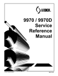
CHAPTER 9 BRAKES Specifications/Torques . . . . . . . . . . . . . . . . . . . . . . . . . . . Brake System Service Notes . . . . . . . . . . . . . . . . . . . . . . Brake Pad Kits . . . . . . . . . . . . . . . . . . . . . . . . . . . . . . . . . . Brake Noise Troubleshooting . . . . . . . . . . . . . . . . . . . . . . Hydraulic Brake System Operation . . . . . . . . . . . . . . . . . Fluid Replacement/Bleeding Procedure . . . . . . . . . . . . Master Cylinder Disassembly . . . . . . . . . . . . . . . . . . . . . Master Cylinder Inspection . . . . . . . . . . . . . . . . . . . . . . . . Master Cylinder Assembly . . . . . . . . . . . . . . . . . . . . . . . . Master Cylinder Installation . . . . . . . . . . . . . . . . . . . . . . . Front Pad Removal . . . . . . . . . . . . . . . . . . . . . . . . . . . . . . Front Pad Assembly . . . . . . . . . . . . . . . . . . . . . . . . . . . . . Front Disc Inspection . . . . . . . . . . . . . . . . . . . . . . . . . . . . . Front Disc Removal/Replacement . . . . . . . . . . . . . . . . . Front Caliper Removal . . . . . . . . . . . . . . . . . . . . . . . . . . . Front Caliper Disassembly . . . . . . . . . . . . . . . . . . . . . . . . Front Caliper Inspection . . . . . . . . . . . . . . . . . . . . . . . . . . Front Caliper Assembly . . . . . . . . . . . . . . . . . . . . . . . . . . . Front Caliper Installation . . . . . . . . . . . . . . . . . . . . . . . . . . Front Caliper Exploded View . . . . . . . . . . . . . . . . . . . . . . Rear Brake Caliper Disassembly . . . . . . . . . . . . . . . . . . Rear Brake Caliper Assembly . . . . . . . . . . . . . . . . . . . . . Rear Brake Caliper Installation . . . . . . . . . . . . . . . . . . . . Rear Brake Caliper Exploded View . . . . . . . . . . . . . . . . Rear Brake Caliper Mounting . . . . . . . . . . . . . . . . . . . . . Troubleshooting . . . . . . . . . . . . . . . . . . . . . . . . . . . . . . . . . 9.1 9.2 9.2 9.3 9.4 9.5-9.6 9.7-9.8 9.9 9.9-9.10 9.11 9.12 9.13-9.14 9.14 9.15 9.16 9.16-9.17 9.17 9.18 9.19 9.20 9.21 9.22 9.23 9.24 9.25 9.26 9 BRAKES SPECIFICATIONS Front Brake Caliper Item Standard Service Limit Brake Pad Thickness .275 / 7.0mm .150 / 3.81mm Brake Disc Thickness .150-.164 / 3.810-4.166mm .140 / 3.556mm Brake Disc Thickness Variance Between Measurements - .002 / .051mm Brake Disc Runout - .020 / .50mm Rear Brake Caliper Item Standard Service Limit Brake Pad Thickness .38 / 9.67mm .150 / 3.81mm Brake Disc Thickness .177-.187 /4.496-4.750mm .167 / 4.242mm Brake Disc Thickness Variance Between Measurements - .002 / .051mm Brake Disc Runout - .010 / .25mm Master Cylinder I.D. .750 TORQUE SPECIFICATIONS Item Torque (ft. lbs. except where noted*) Torque (Nm) Front Caliper Mounting Bolts 18.0 25 Rear Caliper Mounting Bolts 15.0 21 Master Cylinder Mounting Bolts *55 in. lbs. 6.0 Master Cylinder Reservoir Cover Bolt *45 in. lbs. 5.0 Brake Line Banjo Bolt 15.0 21 Front Brake Disc 18.0 25 Rear Brake Disc 24.0 33 Front Wheel Mounting Nuts 15.0 21 9.1 BRAKES BRAKE SYSTEM SERVICE NOTES Disc brake systems are light weight, low maintenance, and perform well in the conditions ATVs routinely encounter. There are a few things to remember when replacing disc brake pads or performing brake system service to ensure proper system function and maximum pad service life. S Optional pads are available to suit conditions in your area. Select a pad to fit riding style and environment. S Do not over-fill the master cylinder fluid reservoirs. S Make sure the brake levers return freely and completely. S Adjust stop pin on front caliper after pad service. S Check and adjust master cylinder reservoir fluid levels after pad service. S Make sure atmospheric vent on reservoirs are unobstructed. S Test for brake drag after any brake system service and investigate cause if brake drag is evident. S Make sure caliper moves freely on guide pins. S Inspect caliper piston seals for foreign material that could prevent caliper pistons from returning freely. S Perform a brake burnishing procedure after installing new pads to maximize service life. BRAKE PAD KITS NOTE: Brake pad part numbers are stamped on the back of the pad for identification purposes. This part number cannot be ordered -- it is included in the chart for reference only. Part numbers on the following chart may change or supercede to a new number. Always refer to the current parts manual for part numbers. Part No. Type Description Application FRONT BRAKE PAD KITS 2201149 - Kit Soft Front brake pad kit. (Contains 4 pads PN 1930731) For dry, dusty conditions. 2200465 - Kit Medium Front brake pad kit. (Contains 4 pads PN 1930815) Production pad (For average use) 2200901 - Kit Severe Duty Front brake pad kit. (Contains 4 pads PN 1930811) For muddy conditions. REAR BRAKE PAD KITS 2201150 - Kit Soft Rear brake pad kit. For dry, dusty conditions. 2200464 - Kit Medium Rear brake pad kit. Production pad (For average use) 2200899 - Kit Severe Rear brake pad kit. For muddy conditions. 9.2 BRAKES BRAKE NOISE TROUBLESHOOTING Dirt or dust buildup on the brake pads and disc is the most common cause of brake noise (squeal caused by vibration). If cleaning does not reduce the occurrence of brake noise, Permatext Disc Brake Quiet (available from most auto parts stores) can be applied to the back of the pads. Follow directions on the package. This will keep pads in contact with caliper piston(s) to reduce the chance of squeaks caused by dirt or dust. Brake Noise Troubleshooting Possible Cause Dirt, dust, or imbedded material on pads or disc Remedy Spray disc and pads with CRC Brakeleent or an equivalent non-flammable aerosol brake cleaner. Remove pads and/or disc hub to clean imbedded material from disc or pads. Pad(s) dragging on disc (noise or premature pad wear) Improper adjustment Insufficient lever or pedal clearance Master cylinder reservoir overfilled Master cylinder compensating port restricted Master cylinder piston not returning completely Caliper piston(s) not returning Operator error (riding the brake / park brake applied) Adjust pad stop (front calipers) Check position of controls & switches. Set to proper level Clean compensating port Inspect. Repair as necessary Clean piston(s) seal Educate operator Loose wheel hub or bearings Brake disc warped or excessively worn Brake disc misaligned or loose Noise is from other source (chain, axle, hub, disc or wheel) Wrong pad for conditions Check wheel and hub for abnormal movement. Replace disc Inspect and repair as necessary If noise does not change when brake is applied check other sources. Inspect and repair as necessary Change to a softer or harder pad 9.3 BRAKES HYDRAULIC BRAKE SYSTEM OPERATION Typical Hydraulic Brake System Must be clear to allow proper diaphragm movement Compensating port compensates for temperature changes by allowing fluid back to master cylinder E C F B A Moveable Brake Pad G D The Polaris brake system consists of the following components or assemblies: brake lever; master cylinder; hydraulic hose; brake calipers (slave cylinder); brake pads; and brake discs, which are secured to the drive line. When the hand activated brake lever (A) is applied it contacts a piston (B) within the master cylinder. As the master cylinder piston moves inward it closes a small opening (compensating port) (C) within the cylinder and starts to build pressure within the brake system. As the pressure within the system is increased, the piston (D) located in the brake caliper moves outward and applies pressure to the moveable brake pad. This pad contacts the brake disc and moves the caliper in its floating bracket, pulling the stationary side pad into the brake disc. The resulting friction reduces brake disc and vehicle speed. As the lever pressure is increased, the braking affect is also increased. The friction applied to the brake pads will cause the pads to wear. As these pads wear, the piston within the caliper moves further outward and becomes self adjusting. Fluid from the reservoir fills the additional area created when the caliper piston moves outward. Brake fluid level is critical to proper system operation. Too little fluid will allow air to enter the system and cause the brakes to feel spongy. Too much fluid could cause brakes to drag due to fluid expansion. Located within the master cylinder is the compensating port (C) which is opened and closed by the master cylinder piston assembly. The port is open when the lever is released and the master cylinder piston is outward. As the temperature within the hydraulic system changes, this port compensates for fluid expansion (heated fluid) or contraction (cooled fluid). During system service, be sure this port is open. Due to the high temperatures created within the system during heavy braking, it is very important that the master cylinder reservoir have adequate space to allow for fluid expansion. Never overfill the reservoir! Fill to 1/4 - 5/16 (.64 - .80 cm) from top of the cylinder. This system also incorporates a diaphragm (E) as part of the cover gasket; and a vent port (F) located between the gasket and the cover. The combination diaphragm and vent allow for the air above the fluid to equalize pressure as the fluid expands or contracts. Make sure the vent is open and allowed to function. If the reservoir is over filled or the diaphragm vent is plugged the expanding fluid may build pressure in the brake system leading to brake failure. When servicing Polaris ATV brake systems use only Polaris DOT 3 high temperature brake fluid (PN 2870990). Polaris brake fluid is sold in 5.5 oz. bottles. WARNING: Once a bottle is opened, use what is necessary and discard the rest in accordance with local laws. Do not store or use a partial bottle of brake fluid. Brake fluid is hygroscopic, meaning it rapidly absorbs moisture. This causes the boiling temperature of the brake fluid to drop, which can lead to early brake fade and the possibility of serious injury. 9.4 BRAKES FLUID REPLACEMENT/BLEEDING PROCEDURE NOTE: When bleeding the brakes or replacing the fluid always start with the caliper farthest from the master cylinder. CAUTION: Always wear safety glasses. CAUTION: Brake fluid will damage finished surfaces. Do not allow brake fluid to come in contact with finished surfaces. BRAKE BLEEDING - FLUID CHANGE This procedure should be used to change fluid or bleed brakes during regular maintenance. 1. Clean reservoir cover thoroughly. C 2. Remove screws, cover, and diaphragm (C) from reservoir. 3. Inspect vent slots (A) in cover and remove any debris or blockage. B A 4. If changing fluid, remove old fluid from reservoir with a Mity Vac pump or similar tool. NOTE: Do not remove brake lever when reservoir fluid level is low. D Mity Vac PN 2870975 5. Add brake fluid to the upper level mark on reservoir. MAX MIN Polaris DOT 3 Brake Fluid PN 2870990 6. Begin bleeding procedure with the caliper that is farthest from the master cylinder. Install a box end wrench on caliper bleeder screw. Attach a clean, clear hose to fitting and place the other end in a clean container. Be sure the hose fits tightly on fitting. NOTE:Fluid may be forced from compensation port (B) when brake lever is pumped. Place diaphragm (C) in reservoir to prevent spills. Do not install cover. 9.5 BRAKES BRAKE BLEEDING - FLUID CHANGE CONT. 7. Slowly pump brake lever (D) until pressure builds and holds. 8. While maintaining lever pressure, open bleeder screw. Close bleeder screw and release brake lever. NOTE: Do not release lever before bleeder screw is tight or air may be drawn into caliper. 9. Repeat procedure until clean fluid appears in bleeder hose and all air has been purged. Add fluid as necessary to maintain level in reservoir. CAUTION: Maintain at least 1/2 (1.27 cm) of brake fluid in the reservoir to prevent air from entering the master cylinder. 10. Tighten bleeder screw securely and remove bleeder hose. 11. Repeat procedure steps 5-9 for the remaining caliper(s). 12. Add brake fluid to the proper level. Master Cylinder Fluid Level Between MIN and MAX lines 13. Install diaphragm, cover, and screws. Tighten screws to specification. Reservoir Cover Torque 45 in. lbs. (5 Nm) 14. Field test machine at low speed before putting into service. Check for proper braking action and lever reserve. With lever firmly applied, lever reserve should be no less than 1/2 (1.3 cm) from handlebar. 15. Check brake system for fluid leaks and inspect all hoses and lines for wear or abrasion. Replace hose if wear or abrasion is found. 9.6 BRAKES MASTER CYLINDER DISASSEMBLY 1. Clean master cylinder and reservoir assembly. Make sure you have a clean work area to disassemble brake components. 2. Place a shop towel under brake line connection at master cylinder. Loosen banjo bolt; remove bolt and sealing washers. CAUTION: Brake fluid will damage finished surfaces. Do not allow brake fluid to come in contact with finished surfaces. 3. Remove master cylinder from handlebars. Cover Diaphragm Banjo Bolt Master Cylinder Piston Assy 4. Remove cover and diaphragm from master cylinder and dispose of the fluid properly. Vent Slots 5. Be sure vents in cover are clean and unobstructed. 6. Remove brake lever. Diaphragm Cover 9.7 BRAKES MASTER CYLINDER DISASSEMBLY CONT. 7. Remove reservoir screws and reservoir. Reservoir Bolts 8. Inspect reservoir seal and replace if worn or damaged. Clean surfaces of the reservoir and master cylinder body. Be sure compensating port (A) and supply port (B) are clean before reassembly. Supply B Comp A 9. Remove outer dust seal. Be ready to catch piston assembly. NOTE: The return spring may force piston out when dust seal has been removed. 10. Remove piston assembly and return spring from master cylinder. Replace piston assembly and spring. Outer Dust Seal 9.8 BRAKES MASTER CYLINDER INSPECTION 1. Clean the master cylinder assembly with clean Dot 3 brake fluid, brake parts cleaner, or denatured alcohol. Dry thoroughly. Inspect the bore for nicks, scratches or wear. Replace if damage is evident or if worn. 2. Inspect parking brake for wear. If teeth or locking cam are worn, replace lever. MASTER CYLINDER ASSEMBLY 1. Install new primary and secondary seals on the piston. Outer Dust Seal Primary Seal Secondary Seal 2. Select the appropriate master cylinder piston installation tool and insert into master cylinder bore. Return Spring Components of Kit 2200879 Type IV Master Cylinder (Hand Brake) .750 (19mm) Installation Tool #2200879 9.9 BRAKES MASTER CYLINDER ASSEMBLY, CONT. 3. Dip piston in clean DOT 3 brake fluid, attach spring to piston, and install assembly into installation tool. CAUTION: Do not attempt to install the piston without the required installation tool. Do not allow the lip of the seals to turn inside out or fold. 4. Push the piston assembly through the installation tool using the plunger handle. Continue pushing until plunger is solid against installation tool. 5. Hold piston assembly inward while removing both tools. Install a new dust seal. Be sure dust seal is completely seated in the groove. NOTE: The piston assembly should move freely in the bore, and spring back against the seal when released. 6. Install reservoir with new seal. Be careful to install and torque screws evenly. 7. Apply a light film of grease to the lever bolt. Install lever and tighten bolt securely. 8. Install parking brake lever assembly. 9.10 Seal BRAKES MASTER CYLINDER INSTALLATION 1. Install master cylinder on handlebars. mounting bolts to 55 in. lbs. (6 Nm). Torque NOTE: To speed up the brake bleeding procedure the master cylinder can be purged of air before the brake line is installed. Fill reservoir with DOT3 brake fluid and pump lever slowly two to three times with finger over the outlet end. 2. Place new sealing washers on each side of banjo line and torque banjo bolt to specification. Master Cylinder Mounting Bolt Torque 55 in. lbs. (6 Nm) Brake Line Banjo Bolt Torque 15 ft. lbs. (21 Nm) Torque to 15 ft./lbs. (21 Nm) Banjo Bolt Sealing Washers Brake Line 3. Fill reservoir with DOT 3 fluid. 4. Follow bleeding procedure on pages 9.5-9.6. Check all connections for leaks and repair if necessary. Polaris DOT 3 Brake Fluid PN 2870990 9.11 BRAKES FRONT PAD REMOVAL 1. Elevate and support front of machine. CAUTION: Use care when supporting vehicle so that it does not tip or fall. Severe injury may occur if machine tips or falls. 2. Remove the front wheel. Loosen pad adjuster screw 2-3 turns. 3. Remove caliper from mounting bracket. 4. Push caliper piston into caliper bore slowly using a C-clamp or locking pliers with pads installed. NOTE:Brake fluid will be forced through compensating port into master cylinder fluid reservoir when piston is pushed back into caliper. Remove excess fluid from reservoir as required. 5. Push mounting bracket inward and slip outer brake pad past edge. Remove inner pad. 6. Measure the thickness of the pad material. Replace pads if worn beyond the service limit. Front Brake Pad Thickness New .275/7.0 mm Service Limit .150 / 3.81 mm 9.12 Measure Thickness BRAKES FRONT PAD ASSEMBLY 1. Lubricate mounting bracket pins with a light film of Polaris Premium All Season Grease, and install rubber dust boots. Polaris Premium All Season Grease PN 2871423 2. Compress mounting bracket and make sure dust boots are fully seated. Install pads with friction material facing each other. Be sure pads and disc are free of dirt or grease. 3. Install caliper on hub strut, and torque mounting bolts. Front Caliper Mounting Bolts Torque 18 ft. lbs. (25 Nm) 4. Slowly pump the brake lever until pressure has been built up. Maintain at least 1/2 (12.7 mm) of brake fluid in the reservoir to prevent air from entering the brake system. PAD ADJUSTMENT 5. Install the adjuster screw and turn clockwise until stationary pad contacts disc, then back off 1/2 turn (counterclockwise). 6. Be sure fluid level in reservoir is between MIN and MAX lines and install reservoir cap. Master Cylinder Fluid Between MIN and MAX lines 9.13 BRAKES FRONT PAD ASSEMBLY, CONT. 7. Install wheels and torque wheel nuts. 8. It is recommended that a burnishing procedure be performed after installation of new brake pads to extend service life and reduce noise. Start machine and slowly increase speed to 30 mph. Gradually apply brakes to stop machine. Repeat procedure 10 times. Front Wheel Nut Torque 15 ft. lbs. (21 Nm) FRONT DISC INSPECTION 1. Visually inspect the brake disc for nicks, scratches, or damage. 2. Measure the disc thickness at 8 different points around the pad contact surface using a 0-1 micrometer. Replace disc if worn beyond service limit. Brake Disc Thickness New .150-.164 (3.810-4.166 mm) Service Limit .140 / 3.556 mm Brake Disc Thickness Variance Service Limit .002 (.051 mm) difference between measurements. 3. Mount dial indicator as shown to measure disc runout. Slowly rotate the disc and read total runout on the dial indicator. Replace the disc if runout exceeds specifications. Brake Disc Runout Service Limit .020 (.50 mm) 9.14 BRAKES FRONT BRAKE DISC REMOVAL / REPLACEMENT 1. Apply heat to the hub in the area of the brake disc mounting bolts to soften the bolt locking agent. 2. Remove bolts and disc. 3. Clean mating surface of disc and hub. 4. Install disc on hub. 5. Install new bolts and tighten to specified torque. CAUTION: Always use new brake disc mounting bolts. The bolts have a pre-applied locking agent which is destroyed upon removal. 18 ft. lbs. (25 Nm) Use new bolts with pre-applied locking agent. Front Brake Disc Mounting Bolt Torque 18 ft. lbs. (25 Nm) 9.15 BRAKES FRONT CALIPER REMOVAL CAUTION: Use care when supporting vehicle so that it does not tip or fall. Severe injury may occur if machine tips or falls. 1. Remove brake pads. See page 9.12. 2. Using a line wrench, loosen and remove brake line to caliper. Place a container under caliper to catch fluid draining from brake line. 3. Remove brake caliper and drain fluid into container. FRONT CALIPER DISASSEMBLY 1. Remove brake pad adjuster screw. 2. Push upper pad retainer pin inward and slip brake pads past edge. 3. Remove mounting bracket, pin assembly and dust boot. Remove Mounting Bracket 9.16 BRAKES FRONT CALIPER DISASSEMBLY, CONT. 4. Remove piston, dust seal and piston seal. 5. Clean the caliper body, piston, and retaining bracket with brake cleaner or alcohol. NOTE: Be sure to clean seal grooves in caliper body. FRONT CALIPER INSPECTION 1. Inspect caliper body for nicks, scratches or wear. Measure bore size and compare to specifications. Replace if damage is evident or if worn beyond service limit. Front Caliper Piston Bore I.D. Std. 1.191-1.192 (30.25-30.28 mm) Service Limit 1.193 (30.30 mm) 2. Inspect piston for nicks, scratches, wear or damage. Measure diameter and replace if damaged or worn beyond service limit. Front Caliper Piston O.D. Std. 1.186-1.1875 (30.13-30.16 mm) Service Limit 1.1855 (30.11 mm) 3. Inspect the brake disc and pads as outlined for brake pad replacement this section. See pages 9.12 and 9.14. 9.17 BRAKES FRONT CALIPER ASSEMBLY 1. Install new O-rings in the caliper body. Be sure groove is clean and free of residue or brakes may drag. 2. Coat piston with clean DOT 3 brake fluid. Install piston with a twisting motion while pushing inward. Piston should slide in and out of bore smoothly, with light resistance. 3. Lubricate the mounting bracket pins with Polaris Premium All Season Grease, and install the rubber dust seal boots. Polaris Premium All Season Grease PN 2871423 4. Compress the mounting bracket and make sure the dust seals are fully seated. Install the pads as shown on page 9.13. Clean the disc and pads with brake parts cleaner or denatured alcohol to remove any dirt, oil or grease. 9.18 BRAKES FRONT CALIPER INSTALLATION 1. Install caliper on hub strut, and torque mounting bolts. Front Caliper Mounting Bolt Torque 18 ft. lbs. (25 Nm) 2. Install brake line and tighten securely with a line wrench. 3. Install the adjuster screw and turn until stationary pad contacts disc, then back off 1/2 turn. 4. Follow brake bleeding procedure outlined on pages 9.5-9.6. 5. Install wheels and torque wheel nuts to specification. Front Wheel Nut Torque 15 ft. lbs. (21 Nm). NOTE: If new brake pads are installed, it is recommended that a burnishing procedure be performed to extend pad service life and reduce noise. Start machine and slowly increase speed to 30 mph. Gradually apply brakes to stop machine. Repeat procedure 10 times. 9.19 BRAKES FRONT BRAKE CALIPER EXPLODED VIEW Adjuster Screw Square O--Rings Piston Pin Boot Pads Caliper Mount 9.20 BRAKES REAR BRAKE CALIPER DISASSEMBLY 1. Make alignment marks on stationary ramp and caliper housing as shown in Ill.1. 2. Remove cotter pin and washer from actuator rod at brake arm. D Adjuster Screw 3. Remove stationary ramp attaching screws (C). 4. Remove ramp assembly (D). It is not necessary to remove rear brake arm unless brake arm or piston pin are being replaced. NOTE: To remove rear brake arm or pin, turn the adjuster screw clockwise with a 3/16 Allen wrench until the piston pin falls out. To remove brake arm, insert a deep well socket into moveable cam to hold lock nut while backing out the adjuster screw. Suggested area to make alignment marks C Auxiliary Brake Arm Ill. 1 5. Apply downward pressure on brake pads directly over retaining pin, releasing pin pressure. Shake pin out of caliper or use a needle nose pliers to remove pin. NOTE: If pins are corroded it may be necessary to spray penetrating oil on pins. 6. Remove pins and brake pads. 7. Insert a drift punch in piston pin hole and tap with a soft face hammer. This will drive out the caliper piston. See Ill. 3. 8. By hand, walk caliper piston back and forth until it can be pulled out of caliper or remove with a caliper piston pliers (internal expanding). Ill. 2 9. Straighten a large paper clip and form a small hook on one end. Polish the end of the clip so there are no sharp edges. CAUTION: Extreme care must be used to avoid scratching the cylinder bore seal ring groove surfaces. 10. Position clip in cylinder bore. With a pushing, twisting action remove large inside seal and small outer dust seal and two small O-ring seals from brake caliper pin hole. 11. Important: Flush cylinder bore with brake fluid and clean with compressed air. Insert Drift Punch Ill. 3 Inspection 1. Inspect cylinder bore for scoring, pitting, or corrosion. A corroded or scored casting should be replaced; light scores and stains may be removed by polishing. Polish any discolored or stained area with crocus cloth only. CAUTION: If you are cleaning the cylinder bore, use finger pressure and rotate the cloth. Do not slide the cloth in or out of bore while applying pressure as scratches may result. Do not use any other type of abrasive or abrasive cloth. 2. Inspect piston. Ill. 4 9.21 BRAKES REAR BRAKE CALIPER ASSEMBLY NOTE: Clean and inspect all components before reassembling. 1. Lubricate new O-rings (A) with brake fluid and install into caliper pin bore. A 2. Lubricate new seals (B) with brake fluid and install into caliper. 3. If piston pin or axillary brake arm were removed, lubricate all sliding surfaces of stationary and moveable brake ramps with a thin coat of Polaris high temp grease. B 4. Align mark of stationary and moveable cam so long side of lobe is in the up position and just to the right of mark on stationary. Alignment marks must be matched and cam positioned correctly, as there are six possible combinations. Polaris High Temp Grease PN 2870616 5. Reassemble adjuster screw through arm and moveable cam. Install washer on screw inside of cam. Reinstall lock nut and tighten until seated, then turn an additional 1/2 turn tighter. 6. Using a new gasket, assemble ramp to brake caliper. NOTE: Align marks of stationary and caliper made in step 1. Torque bolts to 5-6 ft. lbs. 7. Hold caliper so that the brake line fitting hole can be covered with your finger. Close bleeder fitting and add approximately 1/4 ounce of brake fluid to piston bore. CAUTION: Brake fluid will cause damage to painted surfaces. Wipe up any spills at once. Suggested area to make alignment marks Stationary Ramp Long Side of Moveable Ramp Lobe 8. Lubricate piston with brake fluid and install in caliper piston bore, flat beveled end first. 9. Compress piston until seated in caliper and wipe off excess brake fluid from piston area. 10. Attach brake line to caliper assembly and tighten fitting with a flare nut wrench. CAUTION: Brake fluid will cause damage to painted surfaces. Wipe up any spills at once. 11. Reinstall spring plate, brake pads and pad pins to caliper. 12. Pump the handle 10 to 15 times to purge any fluid which may have accumulated between the seals during assembly. 13. Thoroughly wipe the piston and caliper dry. 14. Pressurize the brake system for approximately one minute. NOTE: The parking brake may be used to hold the pressure. 15. Check for “low pressure” leaks by lightly pumping the handle 5 to 10 times. 16. Compress piston into caliper until seated. NOTE: The brake pads will need to be spread enough to accept the brake disc when reinstalling the caliper assembly. 9.22 BRAKES REAR BRAKE CALIPER INSTALLATION 1. Reinstall caliper assembly onto brake disc. 2. Install upper and lower caliper bolts, lock washers, and flat washers (G) to caliper shield (H) and secure caliper assembly to its mounting. 3. Torque caliper specification. mount bolts H to G 4. Install brake line to specified torque. 5. Reinstall the middle chain guard (D) with rear most bolt, lock washer, flat washer (A) and spacer (B). Bolt the forward end of chain guard to the mounting brackets with hardware (C). A B D C 6. Reinstall right front and rear mud flap bolt in footrest. 7. Refill master cylinder with DOT 3 brake fluid and reinstall cover and diaphragm. Caliper Mount Bolt Torque 10 - 12 ft. lbs. (1.4 - 1.7 kg-m) Polaris DOT 3 Brake Fluid PN 2870990 Master Cylinder Fluid Level 1/4 - 5/16 (6 - 8 mm) below top of master cylinder 8. Refer to brake bleeding instructions in this chapter and bleed system. 9. Field test unit for proper braking action before putting into service. Inspect for fluid leaks and firm brakes. Make sure the brake is not dragging when lever/pedal is released. If the brake drags, re-check assembly, installation and adjustment. 10. Machine should be stopped at least ten (10) times from at least 30 miles per hour using the auxiliary brake pedal only. 9.23 BRAKES REAR BRAKE CALIPER Brake Caliper Torque: Seat then tighten an additional 1/2 turn See step 5, page 9.22 Auxiliary Brake Pads Ramp (Moveable) Ramp (Stationary) Auxiliary Caliper Arm (Detail A) 9.24 Torque 5--6 ft./lbs. .69-.83 Kg-m BRAKES REAR BRAKE CALIPER MOUNTING Torque 12 ft./lbs. 1.65 Kg-m Auxiliary Caliper Spacer 9.25 BRAKES TROUBLESHOOTING Brakes Squeal S Dirty/contaminated friction pads S Improper alignment S Worn disc S Worn disc splines Poor Brake Performance S Air in system S Water in system (brake fluid contaminated) S Caliper/disc misaligned S Caliper dirty or damaged S Brake line damaged or lining ruptured S Worn disc and/or friction pads S Incorrectly adjusted lever S Incorrectly adjusted stationary pad S Worn or damaged master cylinder or components S Improper clearance between lever and switch Lever Vibration S Disc damaged S Disc worn (runout or thickness variance exceeds service limit) Caliper Overheats (Brakes Drag) S Compensating port plugged S Pad clearance set incorrectly S Auxiliary brake pedal incorrectly adjusted S Brake lever or pedal binding or unable to return fully S Parking brake left on S Residue build up under caliper seals S Operator riding brakes Brakes Lock S Alignment of caliper to disc. 9.26