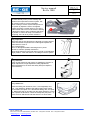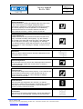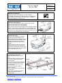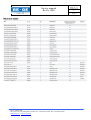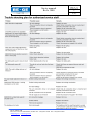
1
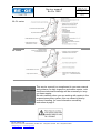
Service manual
Be-Ge 3000
Datum/Date
2008-11-14
Utgåva/Issue
2
Sida/Page
1(11)
30-/31 series
34- series
This service manual is a complement to your user manual
and guidance for daily inspection and easier repairs, note
that some technical knowledge will be necessary to carry
out these repairs.
Be extra carefully when you are working with repairs in the
suspensions scissor system, this can cause injuries by
incorrect handling, for more information see safety
instruction at page 3.
Be-Ge Industri AB
Box 912 S-572 29 Oskarshamn, Sweden Tel. +46(0)491-761800. Fax +46(0)491-81900.
[email protected] www.be-ge.com
Datum/Date
2008-11-14
Utgåva/Issue
2
Sida/Page
2(11)
Service manual
Be-Ge 3000
Contents
Instruction
Safety instruction – Read this
Page
3
1. Inspection & service interval
1.1 Daily inspection
1.2 125 hour service
1.3 1000 hour service
3
3
3
2. Control devices
2.1
2.2
2.3
2.4
2.5
2.6
2.7
Height adjustment
Length adjustment
Attachment
Backrest adjustment
Tilting function
Shock absorber
Connections
4
4
4
4
4
4
4
3. Service & repair instructions
3.1 Lubricate of slide rails
3.2 Dismount of seat cushion
3.3 Dismount of side cover
3.4 Replacement of slide rails
3.5 Replacement of gas springs for tilt
3.6 Replacement of shock absorber
3.7 Replacement of air spring
3.8 Replacement of controls
3.9 Replacement of air valve in controls
3.10 Replacemant of seat trim
3.11 Replacemant of back trim
5
5
5
5
6
6
6
7
7
8
8
4. Assembly of accessories
4.1 Assembly of armrests
9
5. Technical data
5.1 Tolerances in scissor system
5.2 Moment table
5.3 Trouble shooting
9
10
11
Be-Ge Industri AB
Box 912 S-572 29 Oskarshamn, Sweden Tel. +46(0)491-761800. Fax +46(0)491-81900.
[email protected] www.be-ge.com
Service manual
Be-Ge 3000
Safety instruction – Read this
Be extra carefully when you are working with
repairs in the suspensions scissor system, this
can cause injuries by incorrect handling.
When working in scissor system always secure
the system by adjust the seat to it’s highest
position and place a robust object in one of the
bottom frame rails in front of the scissors bearing
to block the scissors, this to make the seat keep
it’s position in case of air drop out or failure in
gas spring, see red dot in picture marked “x”.
X
1.1
Daily inspection
Make sure that no seat functions are blocked by foreign objects.
Check that all belt components are undamaged. Replace the
whole belt kit in case of:
• cut or frayed strap
• worn or damaged hardware including anchor points
• buckle or retractor (if fitted) malfunction
• loose strap stitchings If the seat does not retain in the adjusted
height position, check that there is no leakage in the air system.
1.2
Every 125th hour:
Check all seat functions with respect to satisfactory function of:
Length adjustment, height adjustment, tilting adjustment,
backrest adjustment, air valve and safety belt (see chapter 2,
control devices).
1.3
Every 1000th hour:
Check the sliding rail clearance; max. 1 mm lengthways and
max. 1 mm sideways. Replace the sliding rails if these values
are exceeded, see point 3.4. Lubricate the sliding rails, see point
3.1. Make sure that no oil leaks from the shock absorber. In such
case, replace the absorber. Check the safety belt (see point 1.1).
Check the floor attachment and that there are no loose bolts.
Be-Ge Industri AB
Box 912 S-572 29 Oskarshamn, Sweden Tel. +46(0)491-761800. Fax +46(0)491-81900.
[email protected] www.be-ge.com
Datum/Date
2008-11-14
Utgåva/Issue
2
Sida/Page
3(11)
Service manual
Be-Ge 3000
2.1
Height adjustment
Check the function of raising and lowering the seat. Also check
that the seat remains in the height setting and that the
suspension is satisfactory. If the raising and lowering functions
do not work properly or if the suspension is not satisfactory,
check that the inlet air is in function and does not leak. In
case of defective function, contact a service technician.
2.2
Length adjustment
Push the seat into its end positions and make sure that it runs
freely. Lubricate the sliding rails regularly, e.g. with Texando
20 or similar. First clean with a lint free cloth. If the sliding rails
have a clearance exceeding 1 mm lengthways or sideways,
they shall be replaced. Check that the inlet air is in function and
does not leak. In case of damage or leakage, contact a service
technician.
2.3
Attachment
Make sure that no bolts are loose. Check the attachment of the
seat against floor or frame.
2.4
Backrest adjustment
Check that the back rest controls are undamaged and not defect.
In case of damage, replace the control device or contact a
service technician.
2.5
Tilting function
Check that the tilting function works properly, i.e. the seat can be
tilted forwards and backwards. Check that the inlet air is in
function and does not leak. In case of damage or leakage
contact a service technician.
2.6
Shock absorber
Check that the seat suspension is in function, i.e. that the
suspension is harder when moving the console button upwards
and softer when moving it downwards. In case of defective
function, contact a service technician.
2.7
Connections
Check that no connections (air/electricity), hoses and cables are
defect. In case of visual damage, contact a service technician.
Be-Ge Industri AB
Box 912 S-572 29 Oskarshamn, Sweden Tel. +46(0)491-761800. Fax +46(0)491-81900.
[email protected] www.be-ge.com
Datum/Date
2008-11-14
Utgåva/Issue
2
Sida/Page
4(11)
Service manual
Be-Ge 3000
Datum/Date
2008-11-14
Utgåva/Issue
2
Sida/Page
5(11)
3.1
Lubrication of slide rails
Lubricate the sliding rails regularly, e.g. with Texando
20 or similar. First clean with a lint free cloth. If the sliding rails
have a clearance exceeding 1 mm lengthways or sideways,
they shall be replaced.. See point 3.4.
3.2
Dismount of seat cushion
Losen vecro tape between the seat cushions back and the
backrest, this is easiest done from behind.
Adjust the seat cushion to it’s front position.
Locate the lock under the seat cushion on it’s left side in driving
direction, see the arrow, and push the lock up against the seat
cushion. Pull the cushion one bit more to the front and lift it up.
Note that it in the right position is easy to lift the cushion, if there
is friction the seat plate will risk to be damaged.
3.3
Dismount side cover
Dismount seat cushion as in point 3.2.
Dismount the release handle for the
backrest adjustment by carefully remove
the centre cap with for example a small
screwdriver and pull out the handle.
Dismount the torx screw at the covers
backside.
Dismount plastic rivet by removing the
rivets centre locking (early version) or
dismount the screws (later version), 2pcs
at the covers upper side, and 2pcs under
the cover. Remove the cover.
3.4
Replacement of slide rails
Detach the seat from floor or seat
base.
Dismount protection bellow by sliding
the fastenings against the oblong
holes openings.
Secure the bottom frame by mounting
4 screws in the open holes as shown
in the picture, otherwise the frame
risk to separate.
Dismount the release handle by
stretch it together.
Dismount the screws to the slide rails,
3 at each side.
Reassemble the slide rails, release
handle and protection bellow in
reversed order.
Be-Ge Industri AB
Box 912 S-572 29 Oskarshamn, Sweden Tel. +46(0)491-761800. Fax +46(0)491-81900.
[email protected] www.be-ge.com
Handles
centre cap
Datum/Date
2008-11-14
Utgåva/Issue
2
Sida/Page
6(11)
Service manual
Be-Ge 3000
3.5
Replacement of gas springs for tilt
Dismount seat cushion as in point 3.2.
Adjust the seat to it’s highest position and tilt the seat maximum
backwards.
Loosen the protection bellow as in point 3.4, so you can reach
the lower fastening taps.
Only change one gas spring at the time so the seat is keeping
it’s position.
Dismount the upper locking tap by removing the locking washer.
Release the wire from it’s bracket or the air hose by pushing in
the plastic ring at the connector.
For later versions; loosen lower assembly screw and replace gas
spring.
For earlier wire released gas spring; remove the starloc washer
at the lower fastening tap and replace gas spring.
For earlier air controlled gas spring; thread the gas springs
piston stem out of the release head and replace gas spring,
when reassembling, thread in the piston stem until you feel
friction, then tread out one half turn again. If the gas springs
release head has to be replaced, please contact Be-Ge for
replacing.
Reassemble in reversed order.
Upper lock tap
Lower fastening tap
Early versions
Lower bracket
Late versions
3.6
Replacement of shock absorber
Dismount seat cushion as in point 3.2
For main shock absorber; loosen the wire cover from the
bracket at the absorber by carefully bending up the notch
until you can slide the wire out, then loosen the the wire end
from the adjustment lever.
For DPS absorber; dismount the air hose by pushing in the
plastic ring at the connector and pull out the hose.
When wire / air hose is removed, dismount the upper and
lower fastening bolt and replace the absorber.
Montering sker i omvänd ordning.
Reassemble in reversed order.
3.7
Replacement of air spring
Detach the seat from floor or seat base.
Dismount seat cushion as in point 3.2.
If the seat is equipped with DPS function, disassemble
the main shock absorber by dismounting the upper and
lower fastening bolts and put the absorber aside to get
some free space.
Tilt the seat maximum backwards.
Adjust the seat to it’s highest position and place a
robust object in one of the bottom frame rails in front of
the scissors bearing to block the scissors, this to make
the seat keep it’s position when the air is released.
Air connector
Air spring
Continuation on next page
Be-Ge Industri AB
Box 912 S-572 29 Oskarshamn, Sweden Tel. +46(0)491-761800. Fax +46(0)491-81900.
[email protected] www.be-ge.com
Datum/Date
2008-11-14
Utgåva/Issue
2
Sida/Page
7(11)
Service manual
Be-Ge 3000
Continuation. 3.7 Replacement of air spring
Release the air out of the spring by activating the quick
evacuation, or for the Push-Pull system, press the
button for lowering the seat.
Check so the scissors are stable locked in it’s position.
Dismount the air hose by pushing in the plastic ring at
the connector and pull out the hose, then screw out the
connector of the air spring.
Dismount the upper and lower fastening screw of the air
spring and pull out the air spring in front of the
transverse tube in the upper scissor.
Reassemble in reversed order, note that it’s required to
apply blue Loctite 243 at the connectors treads before
reassembling it.
Air connector
Air spring
3.8
Replacement of controls
Dismount seat cushion as in point 3.2.
Dismount the side cover as in point 3.3.
Dismount the two upper screws and angle the panel
out, when the brackets upper part has passed the seat
frame, press the down the panel so the lower
attachments are released.
Loosen the air hoses from the valves dismount the
wires.
Wire for mechanical tilting is dismounted by loosen the
wire from the handle and pressing together the covers
plastic lockers.
Other wires are dismounted by loosen the wire from the
handle and sliding the covers fastening against the
oblong holes openings.
3.9
Replacement of valve in controls
Dismount seat cushion as in point 3.2.
Dismount the side cover as in point 3.3.
Dismount the controls as in point 3.8, loosen wires and
air hoses is normally not required.
Loosen the air hose to the valve that is to be replaced
and disassemble by dismounting fastening screws.
(Picture shows the panel from behind).
Be-Ge Industri AB
Box 912 S-572 29 Oskarshamn, Sweden Tel. +46(0)491-761800. Fax +46(0)491-81900.
[email protected] www.be-ge.com
Valve
Fastening screw
Datum/Date
2008-11-14
Utgåva/Issue
2
Sida/Page
8(11)
Service manual
Be-Ge 3000
3.10
Replacement of seat trim
Dismount seat cushion as in point 3.2.
Drill rivets at the front handles cover and remove the cover.
The trim is assembled by the sewed plastic ledge around
the seat plates underside.
Start in the back at the ledges ends, see arrow fig 1,to bend
out the ledge from the groove. As the ledge is locked by
barbs in the seat plates outside, see arrow fig 3, press the
ledge inward to avoid destructing the barbs.
When the whole ledge is released, pull the trim off the foam.
The trim also has a sewed in ledge in the seams at the seat
area, this has to be carefully pulled out off the plastic clips in
the foam.
Before you start reassembling the trim, check so the barbs
have the correct shape, see arrow fig 3, otherwise adjust
carefully with pliers or a screw driver.
Reassemble in reversed order.
After reassembling of trim, check so the barbs are locking
the ledge.
Rivet the handle cover with two new rivets 3,2*6mm
(art.no.653004).
3.11
Replacement of back trim
Dismount seat cushion as in point 3.2.
Dismount any armrests and d-loop for seat belt.
For low back; Disassemble any headrest and headrest
socket.
Lean the backrest maximum forward and unzip the trim at
the back.
Separate the locking ledge at the trims underside, see
black arrow.
For backrest with shoulder support; Loosen the schoulder
supports two elastic ribbons by dismounting the metal
hooks in the back of the frame. Lean out the shoulder
support manually and lift it up as soon as it has passed the
ambient foam and trim.
Loosen the metal thread from the plastic clips, see blue
arrows. Pull up the metal thread from the holes in the
backframe, note how the upper thread is locking the lower.
Dismount the trim and pull out the ledges that is sewed
into the seems from it’s plastic clips in the foams front side.
Reassemble in reversed order.
Be-Ge Industri AB
Box 912 S-572 29 Oskarshamn, Sweden Tel. +46(0)491-761800. Fax +46(0)491-81900.
[email protected] www.be-ge.com
Fig 1
Fig 2
Fig 3
Service manual
Be-Ge 3000
Datum/Date
2008-11-14
Utgåva/Issue
2
Sida/Page
9(11)
4.1
Assembly of armrests
The backrest is always prepared for assembling armrests
with three holes and welded nuts at each side of the
backrest.
The lowest hole is placed about 50mm from the side covers
upper edge.
Locate the holes by feeling trough the trim. Armrests will be
assembled by three screws that are screwed trough the
trim, it simplifies to make some small holes in the trim with,
for an example, small screwdriver to not loose the positions.
5.1
Tolerances in scissor system
Tolerance
Gas spring tilt
Max play
0,4mm
Instruction for measure
Measure is to be taken between lower
fastening for gas spring and transversal
tube at the upper fastening.
Scissor system vertically
0,4mm
Measure is to be taken between
transversal tube for upper bearing in the
front and seat frames upper edge.
Scissor system horizontal
0,3mm
Measure is to be taken between upper
fastening for gas spring and for tilting and
seat frames inner edge.
Be-Ge Industri AB
Box 912 S-572 29 Oskarshamn, Sweden Tel. +46(0)491-761800. Fax +46(0)491-81900.
[email protected] www.be-ge.com
Service manual
Be-Ge 3000
Be-Ge Industri AB
Box 912 S-572 29 Oskarshamn, Sweden Tel. +46(0)491-761800. Fax +46(0)491-81900.
[email protected] www.be-ge.com
Datum/Date
2008-11-14
Utgåva/Issue
2
Sida/Page
10(11)
Service manual
Be-Ge 3000
Be-Ge Industri AB
Box 912 S-572 29 Oskarshamn, Sweden Tel. +46(0)491-761800. Fax +46(0)491-81900.
[email protected] www.be-ge.com
Datum/Date
2008-11-14
Utgåva/Issue
2
Sida/Page
11(11)