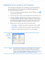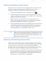
1
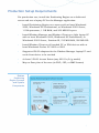
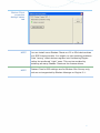
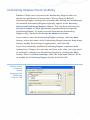
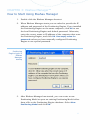
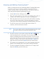
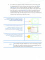
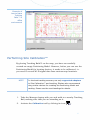
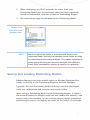
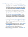
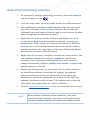
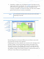
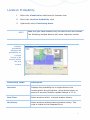
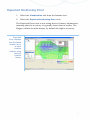
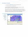
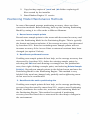
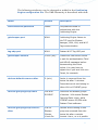
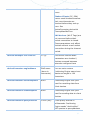
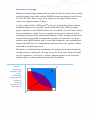
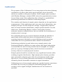
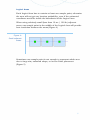
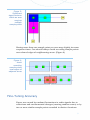
Ekahau
Positioning
Engine 3.1
User Guide
Contents
GETTING STARTED............................................................................ 1
AWARD-WINNING POSITIONING CONCEPT ...................................................
POSITIONING ENGINE COMPONENTS ..........................................................
EVALUATION SETUP REQUIREMENTS ..........................................................
PRODUCTION SETUP REQUIREMENTS .........................................................
INSTALLING EKAHAU POSITIONING ENGINE™...............................................
INSTALLING EKAHAU CLIENT ...................................................................
ACCESSING EKAHAU TECHNICAL SUPPORT ...................................................
1
1
2
3
4
4
5
CHAPTER 1: WI-FI HARDWARE SETUP .............................................. 6
SUPPORTED WI-FI ADAPTERS ................................................................. 6
ACCESS POINT AND POSITIONING ACCURACY GUIDELINES................................ 7
CHAPTER 2: EKAHAU CLIENT™.......................................................... 9
USING EKAHAU CLIENT ......................................................................... 9
CONTROLLING EKAHAU CLIENT VISIBILITY..................................................11
CHAPTER 3: EKAHAU MANAGER™ ................................................... 12
HOW TO START USING EKAHAU MANAGER ..................................................12
LOADING AND CONFIGURING YOUR MAP ....................................................14
PERFORMING SITE SURVEY WITH EKAHAU MANAGER ......................................15
DRAWING AND EDITING TRACKING RAILS™................................................17
PERFORMING SITE CALIBRATION™ ..........................................................19
USING REMOTE CALIBRATION CLIENT FOR HIGHER ACCURACY ..........................21
MITIGATING ADAPTER DIFFERENCES WITH ADAPTER MODELS ...........................22
DISPLAYING DEVICE LOCATIONS AND PROPERTIES ........................................23
DRAWING AND EDITING LOGICAL AREAS....................................................24
SELECTING CONTRIBUTING ACCESS POINTS................................................24
SAVING AND LOADING POSITIONING MODELS .............................................25
SHARING WORK BY MERGING POSITIONING MODELS .....................................26
ANALYZING POSITIONING ACCURACY ........................................................27
CHAPTER 4: EKAHAU MANAGER VISUALIZATIONS.......................... 28
SIGNAL STRENGTHS ............................................................................28
LOCATION PROBABILITY........................................................................30
EXPECTED POSITIONING ERROR ..............................................................31
ACCURACY ANALYSIS ...........................................................................32
CHAPTER 5: MAINTENANCE ............................................................ 33
PERIODIC ACCURACY TEST ....................................................................33
DISASTER AND RECOVERY .....................................................................33
POSITIONING MODEL MAINTENANCE METHODS ............................................34
CHAPTER 6: CONFIGURING POSITIONING ENGINE™...................... 35
WHEN TO CONFIGURE POSITIONING ENGINE, MANAGER, AND SDK ...................35
TCP AND UDP PORTS USED BY EKAHAU PRODUCTS ......................................36
WORKING WITH CONFIGURATION FILES .....................................................37
WORKING WITH POSITIONING ENGINE LOG FILES .........................................42
CHAPTER 7: INTRODUCTION TO EKAHAU SDK™ AND YAX™............ 43
CHAPTER 8: LICENSE UPGRADE ...................................................... 44
HOW TO UPGRADE THE LICENSE ..............................................................44
i
APPENDIX A: ACHIEVING BETTER ACCURACY................................. 45
GENERAL .........................................................................................45
ACCESS POINT PLACEMENT ....................................................................45
CALIBRATION ....................................................................................49
FINE-TUNING ACCURACY ......................................................................51
ii
GETTING STARTED
Award-Winning Positioning Concept
The award-winning concept of Ekahau Positioning Engine™ is to
create a unique Positioning Model for the positioning site, such as a
hospital, office, or warehouse, by recording Wi-Fi network signals
from various locations. This patented process is called Ekahau Site
Calibration™ and it provides significantly higher positioning accuracy
than any other method, such as predicted signal propagation or
triangulation that does not consider the actual radio environment.
Positioning Engine Components
Component
Description
Supported
Platforms
Ekahau
Java-based server that calculates and
Windows® 2000, XP
Positioning
provides the Wi-Fi device locations via
Professional, and
Engine™
Ekahau API
2003 Server
Ekahau SDK™
Ekahau APIs include the SDK Java package,
Windows® 2000, XP
Javadoc, and code examples for reading
Professional, and
location information. Programmers using
2003 Server
other than Java language can alternatively
use the Ekahau YAX™ protocol to read the
location information via TCP socket
Ekahau
Application for creating Positioning Models,
Windows® 2000, XP
Manager™
saving them in the Positioning Engine,
Professional, and
drawing Logical Areas, testing live
2003 Server
positioning, and analyzing accuracy
(requires a laptop)
Ekahau
Ekahau Client must be installed and
Windows® XP,
Client™
running on each PC or PDA that is to be
2000, Pocket PC
tracked. Also required by Ekahau Manager
2002 and 2003
1
Evaluation Setup Requirements
For quick evaluation, install all EPE components on a light laptop PC.
You will need the following items for the evaluation setup:
y
Light laptop PC with at least Windows® 2000, Windows® XP
Professional, or Windows® 2003 Server, 1 GHz processor, 512
MB RAM, and 200 MB HD space
y
Ekahau Positioning Engine™ – Full Install
y
A supported Wi-Fi adapter and driver – see
http://www.ekahau.com/devices/ for supported versions
y
At least 3 standard Wi-Fi Access Points – any 802.11a/b/g
models. The positioning area should have at least 3, preferably 5
or more Access Point signals at each location
y
Map or floor plan of the area (in PNG, JPG, or BMP format)
NOTE
Please see the Positioning Engine Quick Guide to locate your
own laptop using Ekahau Manager.
2
Production Setup Requirements
For production use, install the Positioning Engine on a dedicated
server and use a laptop PC for the Manager application.
y
Install Positioning Engine on a server with at least Windows®
2000, Windows® XP Professional, or Windows® 2003 Server,
1 GHz processor, 1 GB RAM, and 200 MB HD space
y
Install Ekahau Manager and Ekahau Client on a light laptop PC
with at least Windows® 2000, Windows® XP Professional, or
Windows® 2003 Server, Pentium III, 512 MB RAM, 200 MB HD
y
Install Ekahau Client on all tracked PC or PDA devices with at
least Windows® Pocket PC 2002 or 2003
y
Supported Wi-Fi adapters for the Ekahau Manager laptop PC and
each client device to be tracked
y
At least 3 Wi-Fi Access Points (any 802.11a/b/g model)
y
Map or floor plan of the area (in PNG, JPG, or BMP format)
Ekahau
Positioning
Engine Concept
and System
Components
3
Installing Ekahau Positioning Engine™
1.
Double-click Install_Engine_win32.exe. In case of CD
installation, place the CD in the drive.
2.
If the installation does not start automatically, double-click
Install_Engine_win32.exe on the CD.
3. Follow the on-screen instructions and select the components you
wish to install on the target computer (typically Full Install).
Installing Ekahau Client
To locate a wireless PC or PDA, you need to install the Ekahau Client
service on the device, and keep the Client running.
1.
Fully install a supported Wi-Fi adapter on the device. See
http://www.ekahau.com/devices/ for supported adapters.
2.
In case of Windows® 2000, Windows® XP Professional, or
Windows® 2003 Server computer, use the Positioning Engine
installer or CD as described above, but only install Ekahau
Client and the included Wi-Fi drivers.
3.
In case of PDA installation (Pocket PC), first install Ekahau
Client completely on a PC, and synchronize your PDA with
Microsoft® ActiveSync® to install the Pocket PC version of
Ekahau Client.
4
Accessing Ekahau Technical Support
If you encounter problems while evaluating Ekahau software, or if
you have improvement ideas, contact [email protected]. The
Ekahau technical support will respond within 24 hours on business
days (Monday through Friday). Please include the following
information in your e-mail:
y
Detailed description of the problem
y
Log files from Engine, Manager, and Ekahau Client
y
Operating system in use
y
Amount of physical memory (RAM) and processor type
y
Wi-Fi adapter manufacturer, model, and driver version
y
Access point manufacturer and models
Ekahau technical support is free during the evaluation and for 30
days after purchasing a commercial license. After this initial period, a
support package is required for further support and software
updates. Support packages can be purchased from Ekahau.
5
CHAPTER 1: Wi-Fi Hardware Setup
An old driver version of a Wi-Fi adapter is the most common reason
for not receiving signal data from Ekahau Client. Please update your
Wi-Fi adapter driver after installing the adapter:
1.
Insert your Wi-Fi adapter to the PC card slot and refer to its user
manual to properly install the included drivers and utilities.
2.
After installing the Wi-Fi adapter driver, open any adapter utility
or diagnostics tool to display the driver version.
3.
If the driver version number is lower than the one supported, you
need to update the driver. For update instructions, see Start >
Programs > Ekahau > Drivers > Readme.
4.
After installation, open any adapter utility or diagnostics tool to
confirm that the driver was updated properly. If you have trouble
updating the driver, please refer to the adapter and driver
documentation before contacting Ekahau support.
Supported Wi-Fi Adapters
Ekahau Client and Positioning Engine have been tested on Windows®
2000, Windows® XP Professional, and Windows® 2003 Server with
more than 40 leading Wi-Fi adapters, drivers, and PDA devices from
Agere, Avaya, Buffalo, Cisco, D-Link, Enterasys, IBM, Nortel
Networks, Proxim, and other manufacturers.
Click Start > Programs > Ekahau > Client > Device Support or visit
http://www.ekahau.com/devices/ for the latest list of supported WiFi adapters, drivers, and devices.
If you find out that an untested adapter works, please send its model
and driver version to [email protected].
6
Access Point and Positioning Accuracy Guidelines
Ekahau Positioning Engine supports all 802.11a/b/g Wi-Fi Access
Points. Follow these steps for good positioning results.
1.
2.
Provide at least 3 Access Point signals at each location
y
EPE can locate a device with only one AP signal, but a
minimum of 3 signals must be detected by the client device in
each location for better than 5 meter (15 ft) average accuracy
y
Increasing the number of AP signals increases accuracy. The
preferred number of signals per location is 5-10
Install “dummy” Access Points for additional signals
y
3.
4.
To increase the number of AP signals per location, you may
install additional “dummy” Access Points without network
connection. Just power up the dummies. Channel
configuration is not very important as the dummies are not
sending data and will not interference with data networks.
Disable automatic power management features
y
Disable optional power management and self-healing features
for reliable positioning results
y
Enable SSID broadcasting / probe responses to locate Wi-Fi
adapters that do not support passive scanning
Access point placement tips
y
Start from the corners of the intended coverage area.
y
With 3 Access Points the test area size can be, for example,
20x20 m (obstructed) – 40x40 m (open).
y
If the area has low-height obstructions, such as office
cubicles, attach the Access Points (using indoor antennas) to
ceilings or walls above the height of the obstructions.
y
Do not place the Access Points (or antennas) in straight lines
or near one another (less than 5 meters). Use adhesive tape to
secure the antennas for a site survey and testing before
installing them permanently.
7
5.
y
Depending on the desired coverage area, refer to your Access
Point manual to adjust the output power levels.
y
Directional antennas are recommended.
Minimized interference (noise)
y
6.
7.
Strong but diversified AP signals
y
Stronger AP signals provide better resolution and vary less
than weaker signals. This is why the best positioning accuracy
is usually achieved closer to Access Points, whereas areas with
fewer and weaker signals provide lower accuracy.
y
Stronger is better, but moving APs or using directional
antennas to provide different RSSI for areas in close proximity
will help differentiating the areas and improving accuracy.
Site survey
y
8.
High interference may decrease data throughput and
positioning accuracy. Noise can be minimized by proper
channel configuration, for example using 802.11b channels 1,
4, 8, and 11 (for 4 adjacent Access Points), to keep the
channels as separated as possible. Also try to minimize radio
interference from other Wi-Fi networks and radio sources
To ensure that your Access Point placement provides the
maximum coverage, perform a site survey with Ekahau
Manager or Site Survey. Refer to Chapter 3 of this guide
Quick positioning demos with Ekahau Manager laptop
y
To quickly test positioning accuracy, use “dummy” Access
Points only. Record a Positioning Model with Ekahau Manager
and click the Ekahau icon in the upper right corner to display
your laptop’s location. Walk around to test the accuracy
8
NOTE
If you need to move an Access Point after recording Positioning
Model, refer to Chapter 3 to disable the moved Access Points
from the Positioning Model, or re-calibrate the affected area.
CHAPTER 2: Ekahau Client™
Using Ekahau Client
Ekahau Client allows Ekahau Manager to retrieve signal data for Site
Calibration™ (typically from a Wi-Fi adapter installed on a local
computer), and allows the Positioning Engine to retrieve signal data
from client devices for positioning. This is why Ekahau Client must be
installed and running on the Ekahau Manager laptop and on each
client device that is to be tracked.
The Windows® 2000, Windows® XP Professional, and Windows®
2003 Server version of Ekahau Client provides Ekahau Client
Controller / Properties dialog that can be used for:
y
Viewing the Client status
y
Starting and stopping the Ekahau Client service
y
Configuring the allowed or restricted Positioning Engines
y
Enabling or disabling the writing of an Ekahau Client log file
To access Ekahau Client Properties dialog, click the Ekahau icon
in Windows system tray. If the icon is not displayed, start the
Client Controller by selecting Start > Programs > Ekahau > Client >
Ekahau Client Controller.
If you need to view, start, or stop Windows services manually, click
Start > Control Panel > Administrative Tools > Services.
NOTE
Red Client icon (
) on system tray means the Client service
is not running. A yellow exclamation mark (
) means an
error. Click the icon to view error status.
9
Ekahau Client
properties
dialog’s status
tab
NOTE
You can install more Ekahau Clients on PC or PDA devices than
your EPE license permits. You might run into tracking problems
if the “wrong” client devices register into Positioning Engine
before the preferred “right” ones. This can be avoided by
installing as many Ekahau Clients as the license allows.
NOTE
Ekahau Client’s GPS settings are for Ekahau Site Survey only,
and are not supported by Ekahau Manager or Engine 3.1.
10
Controlling Ekahau Client Visibility
Ekahau Client users can select the Positioning Engines that are
allowed or disallowed to locate them. When using the default
Positioning Engine settings (set automatically during the installation),
all available Positioning Engines typically appear in the Recently
Discovered Positioning Engines listbox. You can then uncheck the
Accept checkbox to block positioning requests from that specific
Positioning Engine. To allow requests from known Positioning
Engines only, uncheck the Accept by default checkbox.
If you want to save the Positioning Engine settings, click the Add…
button, select the name of the Positioning Engine from the drop-down
listbox, modify the settings as appropriate, and click OK.
If you have manually modified Positioning Engine communication
settings (see Chapter 6 to see why and how to do this), you may need
to manually configure the Positioning Engine by clicking the Add…
button. Select <custom settings> from the drop-down listbox, fill in
or modify the Positioning Engine details, and click OK.
Ekahau Client
Properties
dialog
displaying the
Positioning
Engines Tab
11
CHAPTER 3: Ekahau Manager™
How to Start Using Ekahau Manager
1.
Double-click the Ekahau Manager shortcut.
2.
When Ekahau Manager starts you are asked to provide the IP
address and password of the Positioning Engine. If you installed
the Positioning Engine on the same computer, click OK to use
the local Positioning Engine and default password. Otherwise,
enter the correct name or IP address of the computer that runs
the Positioning Engine, and click OK. Use empty value for
password unless you have manually configured Positioning
Engine to use special password.
Positioning
Engine Login in
Ekahau
Manager
startup
3.
After Ekahau Manager has started, you can create a new
Positioning Model or open an existing Positioning Model either
from a file or the Positioning Engine database. Select New
Positioning Model and click OK.
12
Ekahau
Manager
Startup options
NOTE
When opening a saved Positioning Model from the Positioning
Engine, make sure that the Positioning Engine is running.
4.
Select View > Signal Strengths. You should see blue bars
indicating signal strength (RSSI) values from active Access
Points. You may also see gray bars indicating the last signal
strengths of Access Points which are no longer detected.
5.
If you do not see any RSSI bars, ensure that your Wi-Fi adapter
and driver version are supported (see Chapter 1 for details).
Update the driver if necessary and restart the computer. If you
still experience problems, contact [email protected].
6.
If you want to change the unit system between Metric and
Imperial, select File > Preferences…
13
Loading and Configuring Your Map
You need a map image for creating the Positioning Model. Supported
map formats are PNG, JPG, and BMP.
1.
To import a map, select New Map… from the File menu.
Alternatively, you can right-click the Maps folder in the left
window, and select New Map… from the context menu.
2.
Click Browse to select a suitable map image.
3.
To ensure that Ekahau Positioning Engine functions accurately,
you must define the correct map scale for each map image. If you
already know how many map pixels equal the map’s selected
distance unit (meter/foot), you can type the value in the Map
Scale field and click OK.
4.
If you do not know the pixels/map unit ratio of the map, leave
the field as zero and click OK. The map should shortly appear.
5.
Click the blinking Measure tool (
) and click a point on the
map – for example the corner of a wall or another measurable
object. Then click another point on the map, at least 3 meters
(10 feet) apart from the starting point. Next, walk to the marked
location on site and measure the real-world distance between the
two points with a measuring tape. Type the real-world distance
in the lower text field, and click Set Map Scale.
Use Measure tool for
setting map scale. After
setting the scale, you
can use the Measure
tool for measuring
distances
on the map
14
Performing Site Survey with Ekahau Manager
When setting up a Wi-Fi network, the Access Point and antenna
locations are typically selected for maximum coverage and data
throughput before installing the Access Points and antennas
permanently. This process is called site survey, and it is also
recommended before recording data for a Positioning Model.
When performing a site survey for positioning, you should observe the
most important positioning attributes:
y
Number of detected Access Point signals at each location.
Accurate positioning requires at least 3, preferably 5-10
y
Signal strength (RSSI) of each AP signal. Stronger is better in
general, however, adjusting APs or using directional antennas to
provide different RSSI for different areas may help differentiating
the areas and improving accuracy
y
Noise level (available separately in Ekahau Site Survey).
Significant radio noise will decrease positioning accuracy. Avoid
noise with standard channel planning (see Chapter 1)
Performing site survey for positioning use with Ekahau Manager:
1.
Display signal strength information in the bottom view by
selecting View > Signal Strengths.
2.
Take your laptop with you and walk around the area while
observing the number of detected signals and their signal
strengths (RSSI) in Ekahau Manager. If necessary, move existing
or add “dummy” Access Points to have at least 3, preferably 4 or
more Access Point signals (blue bars) available in each location.
3.
Once you have at least 3 Access Point signals everywhere, open a
map and draw Tracking Rails as described later in this chapter.
15
4.
Take your laptop with you and walk again around the area,
stopping on the nearest tracking rail every 5-10m (15-30 ft), and
clicking the rail with calibration tool (
) selected. This will
associate received Access Point signals with your physical
location on the map.
5.
After covering most of the important areas, click Ekahau
Manager’s Visualization Tab and select Signal Strength view.
This allows you to observe the 5 strongest Access Point signals at
each location, typically helping network planning. At least the 3
strongest signals should provide average or strong signal
strength for good accuracy.
For complete visualization instructions, see Chapter 4.
Ekahau
Manager with
Signal Strength
(RSSI) display
16
Drawing and Editing Tracking Rails™
Before recording data for the Positioning Model, Tracking Rails must
be placed on the map to indicate possible travel paths between
rooms, corridors, floors, and other locations. The rails are quick to
draw and provide improved positioning accuracy.
1.
Activate Rail tool by clicking its icon (
2.
Place the mouse pointer in the center of a walking path, room, or
corridor, and click the map once to create a starting point.
3.
Move the pointer as far as you can on the path without crossing
any wall or other obstruction. Click the map again to create a
curve point, and continue drawing all essential paths in the area.
4.
To end the current rail, click the right mouse button. To
continue, click the left mouse button.
NOTE
).
You do not need to work on-site while drawing the rails, unless
you want to observe the area when placing the rails.
5.
To select a rail or a curve point, activate the Edit tool
and
click the desired rail or curve point. You can select several
objects by holding down the left mouse button. To move a rail,
press down the left mouse button and drag the rail to another
location. To delete a rail, select it and select Edit > Delete, or
right-click the rail and select Delete from the context menu.
6.
To continue on an existing rail, or to create junctions, place the
pointer on an existing rail or curve point, and left-click once.
7.
To draw rectangular rails that are always in a 45° angle, hold
down the Shift key and left-click once.
17
8.
To connect two adjacent maps or floors, draw a rail curve point
for example in front of an elevator door or staircase, but do not
end the rail. Select another map by clicking it in the Browser
View. When you move the mouse pointer back on the other map,
you will notice a round map link icon with a thumbnail map of
the starting point. Move the cursor in front of the other floor’s
elevator doors and click the map to create a two-way tracking rail
between the two floors or adjacent maps.
1. Starting point of a map link in front
of an elevator. Do not end the tracking
rail but select another map
2. Select another map (another floor or
adjacent map) by clicking it in the
Browser View. Move the mouse pointer
back on map to see a thumbnail of the
first map
3. Click the correct location to place the
map link’s end point. Continue the rail
normally from the end point
NOTE
The location estimates depend much on the rails that you place
on maps. Be careful in marking only the correct paths that are
accessible and used by the tracked devices.
18
Example of
how to place
Tracking
Rails™ in
office
environment
Performing Site Calibration™
By placing Tracking Rails™ on the map, you have successfully
created an empty Positioning Model. However, before you can use the
Positioning Model for locating devices, it needs to be calibrated, i.e.
you need to record Wi-Fi signal data from various map locations.
NOTE
For the best tracking accuracy use only supported adapters
for Site Calibration™ and tracking. Ekahau also recommends
using similar devices for creating the Positioning Model and
tracking. Please see the next headings for details.
1.
Take the Manager laptop with you and walk to a nearby Tracking
Rail, making sure that you are standing on it.
2.
Activate the Calibration tool by clicking its icon (
).
19
3.
Move the mouse pointer to your current location on the rail and
click the map to record a sample point (SP). Do not move away
from your current location until the record dialog disappears (in
10–20 s). While you remain in your current location, turn around
slowly a full 360° to record the signals from all directions.
NOTE
Turning around is important to collect signals from all
directions without your body affecting the readings.
4.
5.
Walk about 3–5 meters along the rail and repeat Step 3 until you
have calibrated the entire area. Please follow the recommended
sample point recording principles for maximum positioning
accuracy:
y
Record a SP every 3–5 meters
y
Record a SP in all Tracking Rail intersections
y
Record a SP in all Tracking Rail ends
y
Record a SP in all locations where the radio environment
suddenly changes. For example, record one SP from both sides
of a door (typically from a room and corridor).
y
In case of open areas, draw a grid of Tracking Rails and record
a SP in the corners of each square. To reach high accuracy,
draw and calibrate at least 5x5 – 3x3 meter grid.
To remove sample points, select Edit > Undo, or alternatively
select the Edit tool (
), right-click the unwanted sample point
and select Delete Sample Point from the context or Edit menu.
6.
To save the calibrated Positioning Model in the Positioning
Engine, select File > Save to Positioning Engine. Type a filename
and click OK. If the Positioning Engine is not running or cannot
be connected, you will receive an error message.
20
Using Remote Calibration Client for Higher Accuracy
For the best tracking accuracy, Ekahau recommends using similar
devices for creating Positioning Model and tracking.
For example, to locate Ekahau Wi-Fi Tags or certain PDA devices
only, you should record the data for your Positioning Model using a
Tag or the PDA, not just any Wi-Fi adapter. Ekahau Card Models will
automatically minimize the differences between any supported Wi-Fi
adapters and devices, but using similar adapter or device for
calibration and tracking phases is always the best option.
1.
Make sure the Tag, PDA, or other device can communicate with
the Wi-Fi network.
2.
In case of a PDA, make sure you are using a supported Wi-Fi
adapter and driver (see http://www.ekahau.com/devices/ for the
list).
3.
In case of a PDA, install Ekahau Client software and make sure it
is running properly.
4.
In case of a Ekahau Wi-Fi Tag, open a terminal program and
connect to the Tag via your laptop’s terminal program (see the
Tag’s user guide for instructions), then type in calibrate<Enter>.
This makes the Tag send data as fast as possible for Site
Calibration™ use. If you hit ESC or the Tag drops off from the
calibration mode for some reason (you will see this if the status
LED is not blinking constantly anymore), just repeat the calibrate
command and continue.
5.
Open Ekahau Manager, select File > Preferences > Calibration
Client, and choose the IP address or friendly name of the device.
This allows Ekahau Manager to retrieve signal data from the
selected remote device for creating the Positioning Model.
6.
Attach or hold the Tag or PDA similarly to the most typical user,
for example using the Tag’s belt clip.
7.
Take your laptop and perform the Site Calibration™ (record data
for your Positioning Model) as described in the previous sections.
21
Mitigating Adapter Differences with Adapter Models
Wi-Fi adapter manufacturers use different radio hardware and
software in Wi-Fi adapters. Even individual adapters from same
manufacturer typically have slightly incompatible scales for observing
the RSSI values. This can cause positioning inaccuracy if the
calibration and tracking steps are performed using different Wi-Fi
adapters. The positioning inaccuracy caused by different adapter
scales is typically 1-5 meters (3-15 ft) depending on the adapter,
without using any mitigation technology.
Ekahau’s patented technology minimizes the positioning inaccuracy
caused by RSSI measurement differences. Ekahau Client and
Manager use method called Ekahau Adapter Models to automatically
apply the correct adapter model to mitigate the differences.
The card models can be found from functions.cfg under Ekahau
Manager’s conf directory.
NOTE
In case of low accuracy for a specific device, open the Devices
tab, right-click on the problematic device, and select
Properties… from its context menu. Make sure the device’s
Wi-Fi adapter and driver are supported. The conversion
function for the specific technology should display OK.
22
Displaying Device Locations and Properties
After drawing Tracking Rails and calibrating the Positioning Model,
you can easily locate client devices by using Ekahau Manager’s
internal positioning test feature.
1.
To locate the Ekahau Manager laptop, click the Ekahau icon
in the upper right corner.
2.
To locate any other device, select Devices tab in the bottom view.
3.
Click the Tracking checkbox for each device on the list to test
tracking in Ekahau Manager. Make sure Ekahau Client software
is installed and running on each PC or PDA to be located. Only
devices running Ekahau Client will appear on the device list.
4.
Right-click on a device and select from context menu:
y
Properties… to display many device properties such as MAC
y
Show RSSI… to display the device-specific signal strengths
y
Follow to automatically keep the device in map display
Device
Properties
dialog for a
tracked
device
NOTE
The device list is retrieved from the Engine. This is why the
Engine must be running to let Ekahau Manager display the
device list. Ekahau Manager however uses its local model
and location test feature for locating the devices.
23
Drawing and Editing Logical Areas
Logical areas are user-drawn areas (polygons) that can have a name
and other location-based properties. Logical areas are used to
determine whether a client device is within a given area.
1.
Activate the Logical Area tool by clicking the icon (
2.
Click the map, move the mouse, and click again until you have
drawn the desired area. Double-click or right-click to connect the
polygon ends and quit drawing.
3.
Right-click the area in Browser View to name the area or to
define custom properties for the area, available for application
developers via Ekahau Java SDK or YAX protocol.
4.
The most probable Logical Area is displayed for each client device
in the Devices Tab when the Tracking checkbox is selected for
the device. Logical area information can also be read from the
Positioning Engine by using Ekahau SDK or YAX.
NOTE
).
Make sure that you place at least one Tracking Rail and record
at least one sample point inside each Logical Area – the
shape of the area does not affect finding it accurately but the
sample points inside the area do.
Selecting Contributing Access Points
All detected Access Points do not necessarily belong to the network
under your control. For example, another company nearby may begin
to use Wi-Fi Access Points that can be observed with Ekahau
Manager. This causes problems if you use all detected Access Points
for calibration, and your neighbors change their AP locations.
1.
Prevent unwanted or unreliable Access Points from being used for
positioning by de-selecting them in Access Point View below the
Browser View, and clicking Apply. Clicking Reset will undo any
changes that were made before clicking Apply.
24
2.
When changing your Wi-Fi network, de-select from your
Positioning Model any Access Points that have been physically
moved or uninstalled, and save it back to Positioning Engine.
3.
The restrictions apply for all maps in the Positioning Model.
Access Point
View below the
Browser View.
NOTE
Data from all Access Points is processed and saved in the
Positioning Model, but only the selected Access Points are used
for positioning and accuracy analyses. This makes it possible to
quickly test positioning and accuracy analyses with different
Access Point combinations without a need for re-calibration.
Saving and Loading Positioning Models
Ekahau Manager can save models either as Ekahau Database files
(.edb), or directly in the Positioning Engine’s internal database.
Typically, the best Positioning Model is always saved in the Engine,
while test calibrations and exercises are saved as files.
After saving a Positioning Model in the Positioning Engine, it takes a
few seconds before the Engine reads the new model into memory, and
starts using it for tracking. As the tracking history queue is emptied,
positioning accuracy can slightly decrease for the next 5–20 seconds.
25
Sharing Work by Merging Positioning Models
1.
Open Ekahau Manager and create a Positioning Model with at
least one map image, then click File > Save to Positioning Engine
2.
IMPORTANT – instruct your team to open the Positioning Model
from the same Positioning Engine before adding maps or making
any changes in their local copies. Merging will not work unless
all team members open the model from the same Engine.
3.
After opening the Positioning Model, add the new map(s) that
were designated to your responsibility, and go calibrate the areas.
It is recommended to save local backups while you proceed.
Select File > Save As… to save the model as a local backup.
4.
When a team member has calibrated his designated area, ask
him to select File > Merge from Positioning Engine. This will
merge the current Positioning Model in the Engine to the local
model in Manager. Nothing is changed in Positioning Engine’s
database or saved at this point. You should now see your changes
with everything the others may have saved in the Engine.
5.
The merge function will add any new maps, rails, sample points,
and Logical Areas into your Positioning Model in Ekahau
Manager. If the same item(s) exist in the Engine and your local
Manager model during the merge operation, your local changes
will not be changed.
6.
After seeing that the merging was successful, click File > Save to
Positioning Engine to save the merged model – now including
your changes – in the Positioning Engine.
7.
Add map links between new adjacent maps or floors.
8.
Repeat steps 4-7 with each team member, and click File > Save
to Positioning Engine.
26
Analyzing Positioning Accuracy
1.
To statistically analyze positioning accuracy, select the Analysis
tool by clicking its icon (
).
2.
Open the map where you are located (inside the calibrated area).
3.
Start walking at a constant restful speed across the areas that
you wish to include in the accuracy analysis. Stay inside the
calibrated area and always click the map in your current location
when changing your direction or speed.
4.
Right-click the map to end the analysis and display the error
vectors in the Map View and statistical analysis on Accuracy
Analysis Tab. Each “arrow” on the map describes the difference
between the actual (clicked) location and a calculated estimate
(constructed from the signal data in the open Positioning Model,
recorded for the same clicked location).
5.
Right-click the accuracy analysis to access its context menu. You
can rename or delete the analysis, update the analysis (to
visualize it after opening an existing model or after you have
changed Positioning Options), display error charts, or export the
analysis data as a text file.
6.
Should the average error be worse than 5m, the likely reason is
an insufficient number of available AP signals, suboptimal
placement of Access Points (or antennas), or too high radio
interference. Please see Appendix A to modify Access Point (or
antenna) locations so that at least 3 AP signals can be detected
throughout the positioning area, and re-calibrate.
7.
Contact [email protected] in case of consistent low accuracy.
NOTE
When opening a previously saved model file (.edb) that
includes Accuracy Analyses, right-click on the analysis name
and select Update Analysis to visualize the analysis results.
27
CHAPTER 4: Ekahau Manager Visualizations
To display the visualizations, you first need to draw Tracking Rails on
a map and record some sample points. Note that the selected/deselected Access Points for each map will affect the visualizations.
Signal Strengths
1.
Select the Visualization tab from the bottom view.
2.
Select the Signal Strength view.
3.
Optionally, select Viewed Signal.
Viewed Signal
Description
Strongest
Displays the RSSI of the strongest Access Point (of all
recorded) at each map location. This can be any
(selected) Access Point that has the strongest signal at
that map location
2nd Strongest
Displays the 2nd strongest RSSI at each map location.
Useful to see what happened if the strongest Access
Point would crash: Is there a backup and how would it
cover the area?
3rd Strongest
Displays the 3rd strongest RSSI at each map location.
Useful to see what happened if the 2nd strongest
(typically a backup) would crash: Is there another
backup Access Point and how would it cover the area?
4th Strongest
See above
5th Strongest
See above
4.
Optionally, select the preferred color scale from the drop-down
color listbox.
28
5.
Optionally, configure the visualization’s grid. Grid affects to the
edge length of the visualization. Use coarser setting when you do
not have much sample points, but want to display as wide
coverage as possible. Use finer level when you have more sample
points and need more accurate visualization.
NOTE
The visualization settings such as the grid size do not affect
positioning in any way.
Signal
Strength
displays the
coverage area
of all
(enabled)
Access Points
in the
Positioning
Model
By switching the view between different Access Points, areas with
poor network coverage can be spotted.
Displaying the accuracy analysis error vectors on the coverage areas
provides insight to network planning problems that might cause
decreased accuracy. For example, poor network coverage typically
correlates with decreased positioning accuracy in the area. To solve
the problem, change Access Point locations or antenna directions, or
add more Access Points in the problematic area.
29
Location Probability
1.
Select the Visualization tab from the bottom view.
2.
Select the Location Probability view.
3.
Optionally select Positioning Mode.
NOTE
Make sure you have selected only one device from the Devices
Tab. Selecting multiple devices will cause imprecise results.
Location
probability
displays the
probability for
a single
device to be
located within
the grid
square
Positioning Mode
Description
Accurate
Displays the probability for a single device to be
located within the grid square, using device history of
around 5 seconds (location update interval x 2.5 s)
Real Time
Same as above with 1 s device location history.
No History
Same as above without device location history. This
view is similar to the Expected Error.
30
Expected Positioning Error
1.
Select the Visualization tab from the bottom view.
2.
Select the Expected Positioning Error view.
The Expected Error view is not using devices’ history information,
meaning that the accuracy is typically lower than in reality. The
Engine utilizes location history by default for higher accuracy.
Expected
Error displays
the estimated
location error
at each
location
without using
device’s
location
history
31
Accuracy Analysis
1.
Select the Visualization tab from the bottom view.
2.
Select the Accuracy Analysis view.
Accuracy Analysis view displays the recorded statistical average
positioning error in colors for each location.
You must have at least one analysis case visible and calculated to
display the visualization. Click the Accuracy Analysis tab, right-click
the analysis case, and select Update from the context menu, after
opening an existing model from a file or Positioning Engine.
Accuracy
analysis
displays the
recorded
average
error in
colors for
each
location
32
CHAPTER 5: Maintenance
Periodic Accuracy Test
Positioning model inconsistency – the difference between recorded
calibration data and actual radio environment – increases with
changes in the environment, such as new walls, cubicle changes,
large containers or furniture, and so on.
Extensive tests in various dynamically changing environments have
proved that during a continuous 30-day field testing the average
positioning accuracy may decrease up to:
y 5-10% in areas with dynamic changes (manufacturing area)
y 10-20% in areas with significant dynamic changes
(shipping & receiving area)
Despite of the good robustness, Ekahau recommends testing active
Positioning Models 3 times a year. Periodic testing can be performed
quickly by opening the Positioning Model from the Positioning Engine,
activating the tracking feature, and walking around while comparing
the actual location to location estimate.
A more accurate and recommended method is to record new sample
points (5–10 % of the number of points in the Positioning Model) to be
analyzed against the original Positioning Model in Ekahau Manager.
For detailed instructions on how to use Ekahau Manager for
positioning accuracy analysis, see Chapter 4.
Disaster and Recovery
Ekahau recommends making backup copies of positioning model and
configuration file(s) in production use. These files are located in
Ekahau Positioning installation folders \EPE3.1\conf and
\EPE3.1\db. If Positioning Engine server data is lost due to hardware
failure, install Positioning Engine after recovering file and operating
systems:
1.
Stop Ekahau Engine 3.1 service through Start > Control
Panel > Administrative Tools > Services
33
2.
Copy backup copies of \conf and \db folders replacing all
files created by the installer
3.
Start Ekahau Engine 3.1 service
Positioning Model Maintenance Methods
In case of decreased average positioning accuracy, there are three
correction methods. Before starting, back up the existing Positioning
Model by saving it in a file under a different filename.
1. Record more sample points
Record more sample points in the areas with decreased accuracy and
save the Positioning Model in the Positioning Engine. This is typically
the fastest and easiest solution, if the average accuracy has decreased
by less than 20%. Note that recording more sample points will not
increase accuracy if the Access Point or antenna locations have been
changed (see option 2 below).
2. Recalibrate problematic areas
If adding new sample points did not help, or the average accuracy has
decreased by less than 30%, delete the existing sample points by
selecting the Edit tool and drawing a rectangle over the problematic
area, then right-clicking a sample point, and selecting Delete Sample
Point(s). Record new sample points in the deleted areas and save the
Positioning Model in the Positioning Engine. This method is very
helpful if the area has changed only partially and neighboring areas
do not need to be recalibrated.
3. Recalibrate the entire positioning site
If adding new sample points did not help, or the average positioning
accuracy has decreased by more than 50%, create a new Positioning
Model, recalibrate the entire site, and save the Positioning Model to
the Positioning Engine. This method is required if positioning
accuracy has decreased due to structural or other major changes in
the environment.
34
CHAPTER 6: Configuring Positioning Engine™
Ekahau Positioning Engine runs as a Windows® NT Service. All you
need to do is keep the service running, thus allowing Ekahau
Manager to save Positioning Models in the Positioning Engine, and
location-based applications to query client location coordinates and
other information from the Positioning Engine.
1.
Ekahau Positioning Engine service starts automatically during
the Windows startup.
2.
If you need to manually start or stop the Positioning Engine
service on Windows® 2000, Windows® XP Professional, or
Windows® 2003 Server, click Start > Control Panel >
Administrative Tools > Services.
3.
To save a Positioning Model in the Positioning Engine, select
File > Save to Positioning Engine in Ekahau Manager. It takes
about 10 seconds after saving to initialize and start using the
new Positioning Model.
4.
After saving a Positioning Model to the Positioning Engine, refer
to Chapter 3 to see how to locate devices on map using Ekahau
Manager. Refer to the Developer Guide to find out how to use
Ekahau SDK or YAX™ protocol to retrieve the location
information to your application.
When to Configure Positioning Engine,
Manager, and SDK
In most cases, the Positioning Engine default installation works well
out-of-the-box. There are times however when you may need to
configure some of the Positioning Engine properties. For example, you
may need to configure Positioning Engine to use another TCP/UDP
port in case another application has already reserved the default port.
35
TCP and UDP Ports Used by Ekahau Products
The table below shows the TCP and UDP ports reserved for Ekahau
Positioning Engine and accompanying products. These ports should
be opened from firewalls if they exist between Ekahau products.
Type
Port
Configuration entry
Description
UDP
8545
Engine.conf: udp.protocol.port
Ekahau Client software uses
(“YAX2”)
UDP
8546
8547
Ekahau Client listens to this
manager.conf:
port to reply to Positioning
deviceConnector.clientUdpPort
Engine broadcasts, to find all
8548
Ekahau Clients in a subnet,
and for positioning requests
Manager.conf:
Ekahau Clients use this port
udp.protocol.port
to send signal data to
(“EkahauClientProtocol”)
TCP
to the Positioning Engine
Engine.conf and
(“EkahauClientProtocol”)
UDP
this port to send signal data
Engine.conf: gatekeeper.port
Ekahau Manager
Java SDK, YAX, Wi-Fi Tags,
Applications, and Manager
use this port to connect to
the Positioning Engine
UDP
8549
Engine.conf: udp.protocol.port
Ekahau Wi-Fi Tags use this
port to send signal data to
the Positioning Engine
NOTE
When using Ekahau Client with Network Address Translation
(NAT), the implementation needs to support 1:1 translation.
Address translations between many to one are not supported.
36
Working with Configuration Files
Positioning Engine, Ekahau Manager, and Java SDK can be
configured by modifying the engine.conf and manager.conf files with
a text editor. The configuration files are located in the conf directories
under the Positioning Engine, Manager, and SDK installation folders.
Save a backup copy of the original file before making changes, and
remember to restart Positioning Engine, Ekahau Manager, or SDK
application to apply the new settings.
The Positioning Engine and Manager Configuration files are in
hierarchical XML format. For example, Ekahau Client’s UDP port
setting is defined in hierarchy conf > deviceConnector >
clientUdpPort. You can see what the hierarchy looks like in the
engine.conf sample below.
If a configuration file does not exist, or contains incorrect values, the
system default values are automatically applied.
If you modify the UDP communication settings between Ekahau
Manager, Positioning Engine and Ekahau Client in the configuration
files, you will also have to change those accordingly in Ekahau Client.
engine.conf and manager.conf files can be found under the conf
folders in the Positioning Engine installation directory.
NOTE
Always save a backup copy of the configuration files before
making changes, and remember to restart Positioning Engine
after making the changes.
37
The following attributes can be changed or added in the Positioning
Engine configuration file. The XML hierarchy is described with dots:
Name
Default
Description
authentication.password
Llama
The password used to
authenticate with the
Positioning Engine
gatekeeper.port
8548
Positioning Engine listens to
this TCP port for Ekahau
Manager, SDK, YAX, and Wi-Fi
Tag communication
tag.udp.port
8549
gatekeeper.timeout
10000 (ms)
Ekahau Wi-Fi Tag UDP port
Timeout for the server socket
to wait for authentication TALK
and HELLO messages before
disconnecting the client
socket. You may have to
adjust this if you test YAX over
Telnet, for example
devices.default remove-after
2 (min)
Device is removed from the
device list after 2 minutes.
These devices do not belong to
either YAX or ECLIENT group
devices.groups.group name
YAX and
These are the default groups
ECLIENT
of devices. YAX means Ekahau
Tags and Palm client, while
ECLIENT means PC/PDA with
Ekahau Client software
devices.groups.group remove-
10s for
Devices which belong to this
after
Ekahau
group are removed from the
Clients,
device list after a certain
10min for
timeout. Use s, m or h postfix.
38
YAX devices
For example 20h means 20
hours
Ekahau Clients (PC, PDA)
have a small timeout because
their own timeouts are
checked before they end up
here. See
deviceConnector.deviceList
CleanupMaxIdleTime
YAX devices (Wi-Fi Tags) are
not removed before their
socket connection is closed.
These parameters only affect
devices without a new socket
connection during the timeout
period.
devices.sweeper run-interval
10 (s)
The former remove-afterparameters are checked /
devices removed between
intervals configured here
deviceConnector.engineName
DNS name
You can set a custom
(leave in
Positioning Engine name here.
comments)
Maximum length is 128
characters
deviceConnector.serverUdpPort
8545
Positioning Engine UDP port
used for receiving data from
client devices
deviceConnector.clientUdpPort
8546
Positioning Engine UDP port
used for sending data to client
devices
deviceConnector.queryInterval
10000 (ms)
Client query interval in
milliseconds. Positioning
Engine sends “AreYouAlive”
UDP queries to queryAddress
39
every n milliseconds
deviceConnector.queryAddress
deviceConnector.deviceList
255.255.255
Engine sends “AreYouAlive”
.255
UDP queries to this address
10000 (ms)
Positioning Engine’s device list
gets cleaned up from old/not
CleanupSweepInterval
responding clients every n
milliseconds
deviceConnector.deviceList
30000 (ms)
If the device has been idle n
milliseconds, the next device
CleanupMaxIdleTime
list cleanup will mark Ekahau
Client device for removal
database.db
db
technologies.XX and
-
The engine database path
Used to format and identify
data, for example BSIDs.
deviceIdentity.XX
Usually there is no need to
edit these
errorCodeTranslations.XXX
-
Internal parameters, no need
to edit
access-rights.XX
-
By default, all Ekahau
Managers with correct
password can update the
model database. Here you can
create read-only managers
which can only browse the
model and track devices. Take
app-id from your manager’s
license.xml, for example
“manager-42”, and change:
<attr name="app-id"
value="manager*"/>
to:
<attr name="app-id"
40
value="manager-42"/>
After this modification (and
restarting Engine) only Ekahau
Manager with app-id
“manager-42” can save a
model in the Engine
productionParameters.XX
-
The production parameters are
described in the Developer
Guide. These production
parameters in engine.conf
override the system defaults,
but any YAX protocol or
Ekahau SDK user can override
these with their own values
(check the developer guide to
see how).
41
Below are the definitions for attributes in manager.conf that differ
from engine.conf:
Name
Default
Description
master.address
127.0.0.1
Positioning Engine’s address
master.port
8548
Positioning Engine’s port. This must be same
as engine.conf file’s gatekeeper.port
Working with Positioning Engine Log Files
Positioning Engine logging can be configured by modifying
log4j.properties file in conf folder under the Positioning Engine
installation folder.
The log files are by default stored in the log folder under the
installation folder. To change the default folder, edit this line:
log4j.appender.file.File = log/Ekahau${logfilesuffix}.log
For example, if you want the log files to be stored under c:\logdirectory, the line should look like this:
log4j.appender.file.File = c:/log/Ekahau${logfilesuffix}.log
Other important logging parameters are the maximum file size and
maximum backup index:
y
The maximum file size means that when the log file has reached
a certain size, it will be backed up to another file and a new log
file is created.
y
The maximum backup index is the maximum amount of the
backup log files. When this number is reached, the oldest file is
deleted and replaced with the second oldest.
In the example below, we have changed the maximum file size to 2
MB and backup index to 7:
log4j.appender.file.MaxFileSize = 2048KB
log4j.appender.file.MaxBackupIndex = 7
42
If you decide not to include general INFO level messages in your logs
at all, change the level to WARN, ERROR or FATAL as follows:
log4j.rootLogger=FATAL, file
CHAPTER 7: Introduction to Ekahau SDK™ and YAX™
Ekahau Positioning Engine (EPE) 3.1 offers two ways for serving
location information to local or remote applications:
y
Ekahau SDK™ Java API for Java developers
y
Character-based TCP protocol Ekahau YAX™ for any
programming language that supports TCP sockets
Both options utilize TCP sockets to connect to the Positioning Engine.
The SDK is just an easy-to-use Java front end for the YAX protocol.
After recording a Positioning Model and saving it in the Positioning
Engine with Ekahau Manager, use Ekahau SDK or YAX Protocol to
read client coordinates, Logical Areas, speed, heading, and other
information from Positioning Engine into your application.
For instructions on how to create location-based applications with
Ekahau SDK and YAX, see the Developer Guide.
43
CHAPTER 8: License Upgrade
How to Upgrade the License
The limited Evaluation version of EPE expires after 30 days.
To track up to hundreds of devices without restrictions, contact
Ekahau Sales to purchase your full license.
After purchasing your license, you need to upgrade each Manager,
Positioning Engine, and SDK installation separately:
y
To upgrade Ekahau Manager, click Start > Programs >
Ekahau > Manager 3.1 > License Upgrade. You may
alternatively click Help > About > Upgrade License, if you are
already running Ekahau Manager. Browse for the license.zip
file and click OK. The About window should now display full
license information.
y
To upgrade the Positioning Engine, select Start > Programs >
Ekahau > Engine 3.1 > License Upgrade. Browse for the
license.zip file and click OK. The Positioning Engine license is
now upgraded.
y
To upgrade Ekahau SDK, select Start > Programs > Ekahau >
SDK 3.1 > License Upgrade. Browse for the license.zip file and
click OK. The SDK license is now upgraded.
44
APPENDIX A: Achieving Better Accuracy
General
This Appendix provides information and guidelines for increasing
positioning resolution using Ekahau Positioning Engine.
Ekahau’s positioning technology is based on probabilistic positioning
framework, which utilizes the latest advances in decision theory,
probabilistic modeling and information theory.
Access Point Placement chapter describes advantages and
disadvantages of various network topologies in respect to potential
positioning resolution. Calibration Chapter examines this issue
further from application’s requirement perspective. The last chapter
describes methods for improving resolution once the hardware
infrastructure is in place.
Access Point Placement
Access point density and antenna placement / orientation are the
most important factors regarding overall positioning resolution. To
achieve repeatable and consistent positioning resolution, Access
Points should be placed to provide unique signal strength and Access
Point combination for each significant location. Every site is unique in
terms of actual network coverage; this section merely describes
Access Point / antenna placement and respective coverage in a
simplified way. Actual signal propagation is a very complex issue due
to environmental factors like reflecting and absorbing materials
(walls, furniture), people or large moving object, etc.
45
Symmetric Coverage
Ekahau’s positioning framework is based on the fact that the received
signal strength indicator values (RSSI) for surrounding Access Points
in a Wi-Fi client device vary with respect to the physical location
where the measurement is done.
As the result of Site CalibrationTM process, positioning framework is
initialized with a site-specific set of calibration data. Each sample
point contains a set of RSSI values for each Wi-Fi Access Point, which
has responded to client’s scan requests at the given location. Every
sample point should be somewhat different. If two sample points that
have not been recorded in immediate vicinity of each other contain
similar data (RSSI values and Access Points match), the probabilistic
framework will have to compromise between these two points, which
can lead to positioning error.
Therefore to eliminate the possibility of having two or more identical
sample points, combined coverage areas for all Access Points should
not be symmetric. In Figure 1 below, sample points in top-left and
bottom-right corners would presumably be similar.
Figure 1:
Symmetric
coverage, two
omnidirectional
antennas are
located in
opposite
corners or an
open space.
46
Asymmetric Coverage
Access points should be placed in corners, preferably in a way, which
minimizes random fluctuations in signal strength caused by people
moving around, opening / closing doors or large objects which may
be moved during operation. In addition one should try to avoid the
above scenario (Figure 1) by covering open areas with more than two
Access Points. Please note that walls and large objects help creating
unique signal / Access Point combinations and therefore may
enhance the resolution. Directional antennas are recommended, if
application requires good resolution in open areas (Figures 2 and 3).
Figures 2 and
3: Omnidirectional and
directional
antennas
Although Ekahau’s probabilistic positioning framework can estimate
device’s location even based on RSSI for one Access Point, it is
recommended that at least three overlapping Access Points were used
throughout the positioning area. In relatively open areas less than
three overlapping channels may lead to degraded location resolution
(two or more sample points have very similar Access Point / signal
strength combinations). More overlapping Access Points provide
better resolution, although overall accuracy will not increase
significantly after exceeding six overlapping Access Points.
47
Adding Access Points
Due to the nature of high-frequency radio signals (2.4 GHz) and
limited signal strength resolution in 802.11 devices, the positioning
resolution and stability tends to be better near Access Points. Ekahau
recommends placing an Access Point in each area where high
resolution is required. It may also be possible to re-arrange the
existing APs in a way which increases resolution in significant areas.
If APs (or antennas) are moved after calibration, their coverage areas
have to be recalibrated. All sample points, which are within original
and new coverage area of the moved Access Point(s), have to be
selected, deleted, and recorded again.
Sometimes removing Access Points from Positioning Model may
improve accuracy. After calibration, Ekahau Manager allows user to
see coverage area contours for each Access Point, from which
calibration device has received signals. If Access Point’s coverage
looks flat or if it has more than one peak, it probably degrades
accuracy (several distant sample points have similar signal values). In
addition APs which are administered by outside parties should not be
used since location, antenna placement, or transmit power may be
changed without notice. The Accuracy Analysis tool can also be used
to select the optimal Access Point combination.
Adding “Dummy Access Points”
The APs used only to improve positioning accuracy do not have to be
connected to the backbone network as long as the client devices are
able to communicate with the Positioning Engine. When placing these
so called dummy APs, make sure they do not share the same SSID as
the AP’s that are used for transferring data. To avoid confusion
caused by some drivers, use only one SSID for the dummies as well.
In addition it is recommended to use a different channel for the
dummies – this is a security measure even though the dummies are
only used for transferring beacons and probes. In addition, the
Wireless Zero Configuration option found in recent Windows®
versions is recommended to be disabled to remove automatic roaming
to unwanted networks.
48
Calibration
The purpose of Site Calibration™ is to map physical locations (bitmap
coordinates of a floor plan) with signal strength values from APs,
which are audible at the given location. Each sample point recorded
with Ekahau Manager contains RSSI values for approximately twenty
Access Point scans. Site calibration data is fitted to a probabilistic
positioning framework in Ekahau Positioning Engine.
The number and density of sample points depends on the application
requirements. If the application only uses area level information, one
sample point per are area might be enough. If application requires
more accurate location information, sample points should cover the
whole area. Positioning Engine is able to interpolate location
estimates between sample points, but not outside the boundaries of
sample points’ coverage.
The calibration device (or external antenna) should be held like it
most likely will be while the device is being tracked. If device’s
receiving antenna is blocked or covered during actual operation,
calibration has to be performed under similar circumstances.
Positioning resolution is good when every sample point in the
Positioning Model is different to some extent and signal information
received from the device being tracked can be mapped to a sample
point (or a group of sample points), which has been recorded in
vicinity of device’s actual physical location.
Sample points should be recorded at every significant location while
avoiding irregular distribution. High sample point density provides
more potential resolution given that the environment (walls, large
objects etc), Access Point placement and number of overlapping
channels provide favourable variation in signal intensities.
Calibrating two or three sample points per specific location sometimes
increases the accuracy by giving the Positioning Engine more
certainty of the signal strength combinations in the location in
question.
49
Logical Areas
Each Logical Area has to contain at least one sample point; otherwise
the area will not get any location probability, even if the estimated
coordinate would be inside the boundaries of the Logical Area.
When using relatively small (less than 10 m2 / 100 ft2) adjacent
areas, one sample point in the middle of the Logical Area will provide
best resolution between the areas (Figure 4)
Figure 4:
Small adjacent
areas.
Sometimes one sample point is not enough to represent whole area
due to large size, awkward shape, or Access Point placement.
(Figure 5)
50
Figure 5:
Significant
signal variance
within an area
requires
multiple
sample points
Having more than one sample point per area may slightly increase
response times. One should always avoid recording sample points
near shared edges of neighbouring areas. (Figure 6)
Figure 6:
Avoid
recording
sample points
near edges of
adjacent areas
Fine-Tuning Accuracy
Errors are caused by random fluctuations in radio signals due to
reflections and environmental changes (causing random errors) or by
two or more similar sample points recorded in distinct locations
51
(causing constant errors). RSSI values can also vary depending on
antenna sensitivity in client devices.
Ekahau Manager provides a tool for statistical accuracy analysis. By
performing several accuracy analysis tests, it is possible to identify
areas where Positioning Engine fails to locate devices systematically.
52
Random Errors
Random errors are caused by constant changes in radio signals. Due
to the nature of high frequency radio signals and limited RSSI
resolution in Wi-Fi devices, it is very difficult to eliminate random
errors completely. One should concentrate on placing APs and
antennas in places where random environmental changes have
minimal effect.
Constant Errors
Constant errors are usually caused by excessive correlation between
two or more sample points. In this scenario it may not be possible for
the positioning engine to estimate an exact location and therefore the
location estimate is a compromise between several locations. Another
cause can be a significant change in the environment.
To correct this kind of errors, first try replacing or adding sample
points in problematic locations. If problems persist throughout the
area, the only solution is to recalibrate the whole area.
If recording or replacing sample points does not help, the problem
resides in the Access Point topology. The only solution for this
problem is adding APs near the problematic areas.
Latency
The coordinate information produced by Ekahau Positioning Engine
is not based on just one RSSI sample. Stabile and accurate tracking
is achieved by combining latest RSSI observation with previous
observations. This is why accurate location estimate is produced with
a few seconds delay.
High sample point density provides better potential resolution, but it
may increase latency particularly in open areas. If the devices are
moving quickly, sample point density should be lower for optimal
latency/accuracy ratio.
53
Ekahau, Inc.
West coast 12930 Saratoga Avenue, Suite B-9
Saratoga, CA 95070
Tel: 1-866-4EKAHAU
Fax: 1-408-725 8405
East coast 620 Herndon Parkway, Suite 200
Herndon, VA 20170
Tel: 1-866-4EKAHAU
Fax: 1-703-481 9834
Europe
Tammasaarenlaituri 3
00180 Helsinki, Finland
Tel: +358 20 743 5910
Fax: +358 20 743 5919
Asia
Suite 1002, Chuang´s Tower
30-32 Connaught Road Central, Hong Kong
Tel: +852 3426 4770
Fax: +852 3426 4061
www.ekahau.com
[email protected]
[email protected]
Legal Notice
Ekahau, the Ekahau logo, Ekahau Site Survey, Ekahau Positioning
Engine, Ekahau Manager, Ekahau T201 and Ekahau Client are
trademarks or registered trademarks of Ekahau.
Other product and company names may be trademarks or trade
names of their respective owners.
The enclosed software contains implementations of Ekahau´s
patent pending inventions.
Under no circumstances shall Ekahau or Ekahau be responsible
for any loss of data, income, or any direct, special, incidental,
consequential or indirect damages howsoever caused.
Copyright© Ekahau, Inc. 2000-2005. All rights reserved.