1
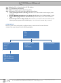
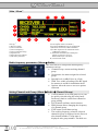
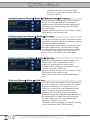
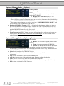
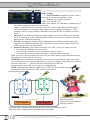
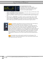
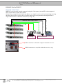
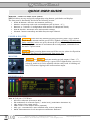
QUICK USER GUIDE MRK 960 - FRONT PANEL FUNCTIONS MRK960 allows an easy and quick configuration using buttons, push knobs and displays. The front panel is functionally divided in the following section: Power & Booster: Receiver and antenna powering; Monitor: monitoring audio with on headphone jack (6.3mm - ¼”); Receiver 1: “receiver 1” configuration and monitor of radio/audio levels; Receiver 2: “receiver 2” configuration and monitor of radio/audio levels; Scan & Squelch: automatic scan and squelch settings; Infrared: remote controlling and MIC setup through infrared. POWER & BOOSTER BOOSTER switch activates antenna powering (boosters) with 12VDC/200mA MAX for each antenna and the green LED is lighted (a blinking LED indicates a faulty condition; in this case power down the device and check for short circuits). Booster supply for antenna A and antenna B are independent, switchable from the radio->options menu. ON/OFF square powering button turns on/off the receiver (when in off position both power line phases are disconnected from power line). MONITOR Monitor 1 and Monitor 2 activates monitor on jack output (6.3mm - ¼”) for receiver 1 and 2, respectively (a green LED is lighted when a receiver is selected). Audio level can be adjusted with the rotary knob. A blinking red led (CLIP) means clipping in the audio monitor output. RECEIVER 1 & 2 Area A: Left part a 3 LED bars: RF level in dBVolt (diversity A & B) FM modulation of received signal (~ audio level) (modulation deviation %) LIN: audio in line output active COM: audio in com output active (optional) GPI: g.p.i. command thru opto-isolated relay, active (optional) DATA: data subcarrier from microphone transmitter detected Wisycom Srl - Via Spin, 156 - I-36060 Romano d’Ezzelino (VI) - Italy tel. +39 0424 382605 fax. +39 0424 382733 http:// www.wisycom.com - e-mail: [email protected] Subject to change without notice Area B: display (256 x 64 pixels yellow OLED display) Area C: 3 Push buttons (membrane) Area D: Push rotary knob (rotate and push to select) Area E: Warning (YELLOW) and Alarm (RED) light indicator: Yellow Fixed light indicator (Warning) when there is no audio in both the audio outputs (COM and LINE) Red Slow Blinking light indicator (Low Alarm) when the battery level of the transmitter is ≤25% Red Fast Blinking light indicator (Medium Alarm) when the battery level of the transmitter is ≤12% Red Fixed light indicator (High Alarm) when a booster (A or B) has a short circuit. Moreover the following message appears on the OLED display: “Over Current on antenna A/B gs restored” OLED DISPLAY Receiver can be easily and quickly configured using a context menu for main function. A draft of the menu structure in the following diagram: MENU: RADIO AUDIO SYNC RADIO: AUDIO: - NOISE REDUCTION SYSTEM - TONE SQUELCH - OUT LEVEL - CALIBRATION TONE - FREQUENCY DIVERSITY - GROUP/CHANNEL - GROUP NAME - SQUELCH - WALK TEST SYNC: - SYNC A TX TO RX FREQUENCY - OPTIONS OPTIONS: - NAME - DISPLAY BRIGHTNESS - DISPLAY LOW: TIMEOUT (sec) -DISPPLAY OFF:TIMEOUT (min) - BOOST ACTIVE ON ANTENNA - INFO - FACTORY PRESET Wisycom Srl - Via Spin, 156 - I-36060 Romano d’Ezzelino (VI) - Italy tel. +39 0424 382605 fax. +39 0424 382733 http:// www.wisycom.com - e-mail: [email protected] Subject to change without notice Main “Menu” 1 7 3 8 D 2 C 4 6 9 5 10 12 11 Following info areas of main “menu” (displayed at device start-up): 1) Receiver Name 2) Current Channel 3) Current Frequency 4) Current Channel Group 5) Squelch level 6) Equivalent TV Channel 7) TX battery status bar 8) TX battery % indication 9) Tone squelch status (on/off/adv.) 10) LOCAL/REMOTE receiver management 11) Remote connection (USB or Ethernet) 12) Audio output level at nominal deviation (6dB before clipping) C) Selectable sub menu (use related push button): it allows to access to Radio/Audio/Sync sub-menus. D) Current menu name Radio frequency parameters (Menu Radio) This menu allows to setup main radiofrequency parameters such as: Channel/Group: current working channel/ group Group name: the name assigned to selected group Squelch level (in dBVolt or in Volt) Walk Test: enable recording of the RF signal for antenna A and B for installation check Options: allow the user to access to options sub menu Setting Channel and Group (Menu Radio Channel/Group) Current channel (0-59) and group (0-39) can be quickly selected using the rotary knob. Push rotary knob to switch from channel to group editing. SAVE button confirms actual selection. FREQ button allows changing the frequency of a channel/group. EXIT button exit without saving. The working frequency related to selected channel & group is displayed on the first row after channel number. Group name is displayed after group number. The third row Wisycom Srl - Via Spin, 156 - I-36060 Romano d’Ezzelino (VI) - Italy tel. +39 0424 382605 fax. +39 0424 382733 http:// www.wisycom.com - e-mail: [email protected] Subject to change without notice (dotted on the picture) is for a user group description; can be edited using the Wisycom Manager software. Setting Frequency (Menu Radio Channel/Group Frequency) Current frequency can be quickly selected using the rotary knob. Push enter button or rotary knob to confirm current field editing and start modifying the following field (frequency integer part decimal part, units=MHz). The new selection can be saved (save button) or push EXIT button to exit without saving. Setting Group Name (Menu Radio Gr name) Each group of frequencies can be associated to a short name and a description. The short name can be edited from the front panel of MRK960. After choosing the group number with the knob, push the knob to edit the name. Turn the knob to change the selected character and push the knob to switch to next character of the name (or use the buttons). Use buttons to save/exit from the name editor menu. Setting Squelch Level (Menu Radio Squelch) Rotate the knob to modify the squelch value in the allowed range (OFF to 1000 Volt or OFF to 60dBVolt, depending on the selected unit). Push the knob to switch between squelch level and squelch unit (Volt or dBVolt). The new selection can be saved (save button) or push EXIT button to exit without saving. NEXT button has the same function as pushing the knob. Walk test (Menu Radio Walk test) The WALK TEST menu allows a 90 sec recording of the received signal for A and B antennas; the result is displayed on the display. The sample rate is one sample per second but the value displayed in mode A&B, A, B (chosen with the first button) is the minimum level of the RF signal received on each antenna. Selecting MAX AB (pushing the first button), the maximum level of signal received is displayed. The unit for RF level is the same chosen for the squelch level (dBVolt or Volt). Change the mode (first button) to restart the recording or just exit from the WALK TEST function. Wisycom Srl - Via Spin, 156 - I-36060 Romano d’Ezzelino (VI) - Italy tel. +39 0424 382605 fax. +39 0424 382733 http:// www.wisycom.com - e-mail: [email protected] Subject to change without notice Options (Menu Radio Options) Options menu: Name: give access to editing the receiver name. Display brightness: to change the brightness of the OLED display. Display low: TIMEOUT (sec) [0÷120 sec]:this setup controls display behaviour as follow: - After a first timer timeout without any input on the receiver (buttons or wheel) the display gost on “REDUCED BRIGHTNESS MODE” - After another timer timeout, the receiver goes into “LOW BRIGHTNESS MODE”, and leaves current menu to be back on TOP MENU. Display off: TIMEOUT (min): [OFF, 5÷240 min]after the timeout without any input on the receiver (buttons or wheel) the display switches off. (OFF=display always power on.) Boost active on antenna: allows to select which antenna input has to be powered on by pressing BOOSTER button from the front panel. Info: push the knob to enter the INFO menu. See below menu. Factory preset: push EXEC button, to restore all functions of the selected receiver as per factory preset. GROUPS and CHANNELS will be unchanged. Use EXIT button to exit without changing. Options (Menu Radio Options Info) Info menu: Range: info about the frequency limits of the receiver. Temp: internal temperature of MRK960. Ant. A and Ant. B: the measure of the output current for powering the boosters connected on antenna input A e B connectors. The current measurement is active only when boosters are switched on. The booster supply voltage is 12 Volts. Serial: serial number of the MRK960 receiver. Errors: number of internal errors detected by the receiver, useful for service or maintenance. App: release version of the main application firmware. App bl: release version of the main application firmware updater (bootloader). Netw: release version of the network communication firmware. Netw bl: release version of the network communication firmware updater (bootloader). DSP: release version of the DSP firmware. Wisycom Srl - Via Spin, 156 - I-36060 Romano d’Ezzelino (VI) - Italy tel. +39 0424 382605 fax. +39 0424 382733 http:// www.wisycom.com - e-mail: [email protected] Subject to change without notice Audio parameters (Menu Audio) Audio settings: Noise reduction (compander system): allows choosing the preferred compander system. Tone sq.: tone squelch selection: <Off>, tone squelch is off. <On>, tone squelch is on and audio is enabled only if the remote management sub-carrier is detected. <Adv>, in advanced mode it is possible to use PTT (push to talk) function and manage a remote commutation on secondary audio output or more complex commands (ex. GPI, selectable with the config submenu, first button, active when ADV is selected; see picture below). Out level: It is possible to attenuate the audio output level at 0/6/12 dB from the nominal level. A switch for a further 30dB attenuation for MIC level output is located on the back panel near the XLR audio connector. Cal tone: activating this option a 1KHz calibration tone is enabled on audio output. The output level is 6dB below clipping and it is possible to activate audio output on LINE out, COM out (optional) or in both outputs. Frequency diversity: This option is normally set to OFF. Set to YES when you need: to increase the reliability in case of failure to increase the reliability in case of transmitter batteries empty to increase the security against fading due to reflections on the radio link When a receiver is set to frequency diversity YES, the audio output is calculated from the best RF signal received from the two receivers. WARNING: two transmitters tuned with the two receivers must be placed on the same audio source and must have the same configuration (ex. gain, tone squelch setting, RF power, distance from the audio source….). NOTE: the Noise reduction can be different. Frequency diversity in each receiver can be set independently. NOTE: With frequency diversity enabled (set to YES), the Tone Squelch menu allows only the setting options ON and OFF (the ADV option is not allowed). Frequency diversity example: RX1 A B A B f1 f1 f2 f2 Freq. Diversity YES Noise Red. ENR Audio output RX1 RX2 TX2 f2 Freq. Diversity NO Noise Red. ENC Audio output RX2 TX1 f1 RX1 tuned on f1 with Frequency Diversity set to YES. RX2 tuned on f2 with Frequency Diversity set to NO. Audio output RX1 is calculated from the best RF signal received from the two receivers. Audio output RX2 is calculated from the RF signal received from RX2. Wisycom Srl - Via Spin, 156 - I-36060 Romano d’Ezzelino (VI) - Italy tel. +39 0424 382605 fax. +39 0424 382733 http:// www.wisycom.com - e-mail: [email protected] Subject to change without notice Tone squelch advanced config: This submenu allows access to the matrix configuration of audio outputs and GPI command (COM and GPI are optional) depending on the subcarrier tone from the transmitter. On the row TSQ OFF it is possible to activate or not the audio output on LINE and/or COM outputs with or without subcarrier signal present. On the row TSQ ON it is possible to activate or not the audio output on LINE and/or COM outputs only when the subcarrier signal is present. Without subcarrier signal all outputs are off. On the first row of TSQ ADV it is possible to activate or not the audio output on LINE and/or COM outputs plus GPI command only when the subcarrier signal is not present. On the second row of TSQ ADV it is possible to activate or not the audio output on LINE and/or COM outputs plus GPI command only when the subcarrier signal is present. AUTO-SET SCAN is an automatic scan function for all active frequencies of the selected group. This is a quick way to find the lowest noise frequency to work with. Once pushed, you need to select the group of frequencies to scan and an optional voltage level line on the graph, just for your reference. Pushing START the receiver (after one message) starts to scan all the frequencies and shows the result on the display. Push the knob to change the x-axis of the graph between channel number and rank; this second choice displays the less noisy channels on the left part of the graph. Rotate the knob to switch between all the channels. Select the squelch to off to hear the received signal even if it’s RF signal is lower than the squelch of the receiver. Pushing SELECT button the receiver will be tuned on the selected channel thru the knob. SQ is an automatic way to quick setup the squelch for current frequency. The transmitter must be off, then push SQ button to let the system find the optimal value. This setup can be saved or not saved. Wisycom Srl - Via Spin, 156 - I-36060 Romano d’Ezzelino (VI) - Italy tel. +39 0424 382605 fax. +39 0424 382733 http:// www.wisycom.com - e-mail: [email protected] Subject to change without notice REMOTE MANAGEMENT Network connections MRK960’s can be easily cascade connected using the 2 usb ports ((current SW version support 4 racks cascade max for each daisy chain). On the below example the unit on the top behave as a single 8 receiver rack (concentrating remoting data from the below receivers); this way all the units can be easily monitored/configured thru a single USB interface or Ethernet connection (a single IP). Analogue audio cables (XLR) Ethernet 10/100 Base Tx (RJ45) USB Monitoring D i g i t a l D i g i t a l A n a l o g u e Audio distribution USB-A interface to link with computer and other receiver. USB-B connector to cross link with other receiver, only Wisycom Srl - Via Spin, 156 - I-36060 Romano d’Ezzelino (VI) - Italy tel. +39 0424 382605 fax. +39 0424 382733 http:// www.wisycom.com - e-mail: [email protected] Subject to change without notice Wisycom Srl - Via Spin, 156 - I-36060 Romano d’Ezzelino (VI) - Italy tel. +39 0424 382605 fax. +39 0424 382733 http:// www.wisycom.com - e-mail: [email protected] Subject to change without notice