1
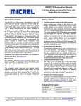
THIS USER GUIDE IS APPLY FROM SOFTWARE VERSION 3.X User Guide for Bed and Door Guard PIR900 KNOP ELEKTRONIK A/S Fabriksvej 20DK-7600 StruerMail: [email protected]Web: www.knop.dkTlf.: +45 9784 0444Fax.: +45 9784 0666 Content: Intended use of PIR900 page 3 Placing page 3 Placing of PIR900 as bed guard page 3 Placing of PIR900 as door guard page 4 Change between bed and door guard page 4 Operation page 4 Operation with ByPass page 4 Programming guide page 5 Settings page 5 ByPass/Delay settings page 6 Battery alarm page 6 Battery change page 6 Control of coverage area page 6 Cleaning page 7 Disposal page 7 Relay output page 7 Activation range page 7 Technical data page 8 Accessories page 8 -2- Intended use of PIR900: PIR900 is a transmitter designed to transmit codes to a wireless receiver in KNOP’s 900series Transmission takes place when a person moves over the edge of the bed, or when the person walks on the floor. Please notice that the covering range has been described under ”Control of coverage area”. PIR900 can also register opening and closing of a door by means of the accompanying magnet. Placing: PIR900 must be tested when it has been installed,. Position yourself outside the activation range. Move into the activation range and note whether the diode ”DET.” flashes on the front of PIR900, every time it is activated. Bed Bed PIR900 PIR900 Activation area Activation area Placing PIR900 as bed guard: Place PIR900 on the wall with the accompanying velcro tape, or put it in the plinth if it shall be placed on the floor. Please notice that PIR900 is an infra-red detector which reacts to changes in temperature, therefore do not place it in direct sunlight, in draft from open doors and windows, or other things that may cause considerable changes in temperature. -3- Placing PIR900 as door guard: Mount PIR900 on the door frame with the accompanying velcro tape. Mount the accompanying magnet on the door beside PIR900 so that the upper edges are in alignment. Distance between PIR900 and magnet should be max. 10 mm. The magnet can be placed on the right as well as left side of PIR900. Change between bed and door guard: The factory always delivers PIR900 in bed guard mode. By pressing for app. 5 sec. PIR900 shifts between bed and door guard. When PIR900 has changed mode, it will acknowledge with a sound. The display will show or for either bed or door guard. Operation: NB: Operation is identical for both bed and door guard. Press for app. 2 sec. to turn PIR900 on. Light will now be lit in ON or OFF, and PIR900 will acknowledge with a sound. After that PIR900 can be operated. By pushing PIR900 shifts between ON and OFF. When PIR900 is turned on, please check that it is in the desired mode. (see section ”Change between bed and door guard”). Operating with ByPass: NB: Operation is identical for both bed and door guard. If is ON in the programming menu (see section ”Programming guide”), this function offers the possibility to start with delay. Thereby it is possible to get out of PIR900’s activation range, before it monitors a movement. The delay is 10 sec. If PIR900 is activated, it does not transmit the alarm until the delay This enabled the nurse to cancel the alarm by pressing -4- has passed. briefly or turn PIR900 off with Programming guide: NB.: If no selection has been made within 15 sec., it will exit programming. If PIR900 exits the programming menu, possible changes will not be saved • Press • The display flashes • After that PIR900 shifts to programming menu. • The display now shows • When pressing the ON and OFF indicators change status. • When pressing you shift between the possible settings (They will be and at the same time for 5 seconds (start with F1). and light is now on in the ON or OFF indicator. mentioned later in the section ”Settings”). • After the software version exit the programming menu. • Possible changes have been saved. is shown and after pressing again you • If you have advanced one step too far, you will have to step all the way through and start all over again. PIR900 remembers the changes you have made in the setup. Settings: ByPass: Select delay ON or OFF. (ByPass has been set for OFF from the factory) (see section ”ByPass/Delay settings”) Delay: Indicates the time it shall take from one alarm to the possible occurrence of the next alarm. 0-9 min. (From the factory Delay is set at 1) (see section ”ByPass/Delay settings”) Pulse: Indicates how many activations it takes within 4 sec. to release an alarm. (From the factory Pulse is set at 2) Led Enable: Select indecator status to be ON or OFF. (From the factory LedEnable is set ON) Unit / Seperate Transmission codes (For future use). (From the factory Unit is set ON) DoorClose: Indicates whether an alarm or a status shall be transmitted when the door is being closed. (From the factory DoorClose is set OFF, which means a status will be sent) Software version: Indicates which software version is installed in the product. -5- ByPass/Delay Settings: You can set the ByPass and Delay times in various ways in PIR900. In this section we shall try to explain two examples of settings. In the first example ByPass is set at on and Delay is set at d1 When ByPass is set at ON, PIR900 will begin countdown from 9 to 1, after which it will begin transmitting an alarm. If Delay is set at d1, PIR900 cannot transmit again until after one minute’s silence in front of the PIR-element. In the other example ByPass is set at off and Delay is set at d0 When ByPass is set at OFF, PIR900 will begin transmitting an alarm when it is activated. If Delay is set at d0, PIR900 can transmit when it has been activated in front of the PIRelement. Battery alarm: The battery is been checked every time an alarm has been transmitted. At low battery voltage there will be a beep every 7-10. sec. When an alarm is transmitted the display will show ”LO BA”. At the same time a low battery status is sent to the receiver e.g. RX900-LED. Battery change: • • • • Remove the battery cover on the back of the product. Insert 2 new alkaline LR-6 batteries. Remember to position them correctly. See the marking at the bottom of the battery box. Check that the product works properly. Control of coverage area: One person will activate PIR900 at short intervals, while another person systematically walks around in the area and marks the coverage on a sketch of the building and the area. The sketch is kept in the office so that everybody who shall operate the system can see the covering range. Alarms cannot be received outside the covering range. The covering area may be extended by using a repeater system from Knop Electronics. Contact your dealer for further information. -6- Cleaning: The product may be cleaned with a damp cloth or alcohol tissue. Disposal: The product must not be disposed of together with general household garbage. Relay output: Pin 1: GND Pin 2: +3V Pin 3: NC Pin 4: NC Pin 5: NC Pin 6: NC Pin 7: COM. Pin 8: Normal Open. (black) (red) (green) (yellow) Activation range: PIR900’s infra-red activation range is ±52° on the horizontal plane and ±15° on the vertical plane. Straight forward-looking, 5-10 meters, falling periphery. Technical data PIR900: -7- Technical data PIR900: Frequency: Transmitter protocol: Range: 869.212 MHz (FM) KNOP900 >50m depending on the conditions Battery type: Operating voltage: Operating time (expected): Low battery alarm/indicator: 2 pcs. 1.5V LR6/AA/E91 ProAlkaline (2700mA/h) 3.3V 12 months at 10 transmissions per day. app. 1/3 remaining capacity. Power consumption stand by: Power consumption inactive: Power consumption active: <150μA. <230μA. <50mA average on one transmission. Ambient environment: Ambient temperature: Indoor use. <90 % humidity non-condensing. 0-40° C Cabinet type: Cabinet dimensions: White ABS W: 65mm, H: 120mm, D: 22mm. Tightness: IP20 Connections: 8 pole modular plug: Potential free relay output pins 7 & 8 max. 24V/100mA. Pin 1 & 2 DC supply, other pins must not be used. Weight incl. batteries: 145g Accessories: Product: Article number: Product: Article number: Product: Article number: Inter-connecting cable. MK-201. Plinth. Sokkel-PIR2003. Magnet. 2301. -8KNOP Electronics reserves the right to change the user manual without notice. PIR900 Userguide - v10ENG