1
INSTRINSICALLY SAFE CALIBRATOR User Guide version 3 Manual revision a Dear user, We have made every effort to ensure the accuracy of the contents of this manual. Should any errors be detected, we would greatly appreciate to receive suggestions to improve the quality of the contents of this manual. The above not withstanding, we can assume no responsibility for any errors in this manual or their eventual consequences. We reserve rights to make modifications to this manual without any further notice. For more detailed technical data about the MC2-IS Intrinsically Safe Calibrator, please contact the manufacturer. © Copyright 2008-2009 BEAMEX OY AB Ristisuonraitti 10 FIN-68600 Pietarsaari FINLAND Tel +358 - 10 - 5505000 Fax +358 - 10 - 5505404 E-mail: [email protected] Internet: http://www.beamex.com 8813000 / UEMC2-IS / 001239 Trademarks and Statements QCAL® is a registered trademark owned by Beamex Oy Ab. Other trademarks are property of their respective owners. MC2-IS contains licensed software which requires that the source code is available for You. Please contact Beamex to obtain it. MC2-IS is based in part on the work of the FLTK project (http://www.fltk.org). Contents Contents Part A, General Introduction ......................................................................................... 2 About This Manual ................................................................................... 2 Typographical Conventions ............................................................... 3 Unpacking and Inspection ........................................................................ 3 MC2-IS Hardware................................................................................. 4 Connections ............................................................................................. 5 Pressure Modules .............................................................................. 6 Connectors on the Left Side of MC2-IS ............................................. 7 Terminals ........................................................................................... 7 Support for Table Top Use ....................................................................... 8 Memory .................................................................................................... 8 Display...................................................................................................... 8 Keyboard .................................................................................................. 9 Batteries ................................................................................................. 10 About the Charger and the Charging Procedure ............................. 11 Removing/Replacing the Batteries................................................... 12 PC Communication .......................................................................... 13 MC2-IS Firmware ............................................................................... 14 General Description................................................................................ 14 Startup Procedure ............................................................................ 14 Basic Mode and Higher Level Functions ......................................... 14 Basic Mode's User Interface .................................................................. 15 The Status Bar ................................................................................. 15 Windows 1 and 2 ............................................................................. 15 The Function Key Bar ...................................................................... 16 Menu ................................................................................................ 16 Configuration Windows .......................................................................... 17 Field Types Available for Editing Data ............................................. 18 MC2-IS User Guide Contents MC2-IS Options ................................................................................. 22 Hardware Modules/Options .................................................................... 22 Other Devices .................................................................................. 23 Safety ................................................................................................. 24 Symbols Used ........................................................................................ 24 Ex Information and Approvals ................................................................ 25 Safety Precautions and Warnings .......................................................... 25 General Warnings ............................................................................ 26 Warnings Concerning Electrical Measurement and Generation ....................................................................................... 26 General Warnings Concerning Pressure Measurement .................. 27 Warnings Concerning High Pressure .............................................. 28 Disposal of Waste Electrical and Electronic Equipment............... 29 Service ............................................................................................... 30 Firmware Update .................................................................................... 30 The Battery Charger ............................................................................... 30 Resetting MC2-IS ................................................................................... 30 Recalibrating MC2-IS ............................................................................. 31 Cleaning MC2-IS .................................................................................... 31 Part B, Startup and Basic Operation Starting MC2-IS ................................................................................. 34 Startup Procedure .................................................................................. 34 Basic Mode, Defined .............................................................................. 35 Measuring .......................................................................................... 37 Current Measurement ............................................................................ 39 Frequency Measurement ....................................................................... 40 Pressure Measurement .......................................................................... 41 Connecting and Disconnecting External Pressure Modules ............ 42 Zeroing a Pressure Module.............................................................. 43 Pulse Counting ....................................................................................... 44 Resistance Measurement ...................................................................... 45 Switch State Sensing ............................................................................. 46 Temperature Measurement (RTD) ......................................................... 48 Temperature Measurement (Thermocouple) ......................................... 49 Voltage Measurement ............................................................................ 50 MC2-IS User Guide Contents Generating/Simulating ...................................................................... 51 Changing the Generated/Simulated Value............................................. 52 Spinning and Manual Stepping ........................................................ 52 Current Sink ........................................................................................... 54 Frequency Generation ........................................................................... 55 Pulse Generation.................................................................................... 56 Resistance Simulation ............................................................................ 57 RTD Sensor Simulation .......................................................................... 58 Thermocouple Simulation ...................................................................... 60 Voltage Generation ................................................................................ 62 Tools Menu ........................................................................................ 63 Function Info........................................................................................... 64 Alarms .................................................................................................... 65 Damping ................................................................................................. 66 Leak/Stability Test .................................................................................. 67 Stepping ................................................................................................. 69 Ramping ................................................................................................. 72 Manual Stepping .................................................................................... 74 Display Mode and Special Measurements ............................................. 77 Error % ............................................................................................. 78 Error in Input Units ........................................................................... 79 Error in Output Units ........................................................................ 80 Percentage ....................................................................................... 81 Scaling ............................................................................................. 82 Deviation .......................................................................................... 83 Showing Data on the Additional Info Row .............................................. 84 Resetting and Clearing Additional Info Row / Calculations.............. 87 Part C, Advanced Operation and Configurations Utilities Menu ..................................................................................... 90 About MC2-IS ......................................................................................... 90 User Setups for n & o .......................................................................... 91 Date/Time ............................................................................................... 92 General Settings..................................................................................... 93 Calibrator Adjustment ............................................................................. 94 MC2-IS User Guide Contents Custom Test Point Sets ................................................................... 95 Custom Transfer Functions ............................................................. 97 Custom Pressure Units .................................................................. 100 Related Information ........................................................................ 101 Things to Consider when Measuring Pressure .................................... 102 General .......................................................................................... 102 Pressure Type................................................................................ 102 Pressure Modules and their Naming Conventions ........................ 103 Square Rooting .............................................................................. 104 Thermocouple Measurement/Simulation, Connections and Troubleshooting ................................................................................... 105 Internal Reference Junction ........................................................... 105 External Reference Junction .......................................................... 106 Error situations ............................................................................... 109 Resistance and RTD Measurement, Connections ............................... 110 4-wire System ................................................................................ 110 3-wire System ................................................................................ 110 Using a Compensation Loop ......................................................... 111 2-wire System ................................................................................ 111 Current Measurement Parallel to a Test Diode, Connections .............. 112 Parallel Functions in MC2-IS ................................................................ 113 Part D, Calibration General ............................................................................................ 116 Phases of Instrument Calibration ......................................................... 117 As Found Calibration ..................................................................... 118 Adjustment ..................................................................................... 118 As Left Calibration.......................................................................... 119 Calibrating an Instrument .............................................................. 120 A Calibration Procedure Using MC2-IS................................................ 120 Examples of Instrument Calibration ..................................................... 121 Pressure Transmitters.................................................................... 122 Temperature Indicators and Recorders ......................................... 124 Electrical Limit Switches ................................................................ 126 Temperature Sensors .................................................................... 128 MC2-IS User Guide Contents Appendixes Appendix 1, Technical Data ........................................................... 132 MC2-IS General Specifications ............................................................ 132 Electrical Measurements ...................................................................... 133 Voltage Measurement .................................................................... 133 Current Measurement .................................................................... 133 Frequency Measurement ............................................................... 134 Pulse Counting............................................................................... 134 Switch Test .................................................................................... 134 Electrical Generation, Sensor Measurement and Simulation .............. 135 mV Measurement (T/C-Terminals) ................................................ 135 mV Generation (T/C-Terminals)..................................................... 135 Voltage Generation ........................................................................ 136 mA Generation (Source/Sink) ........................................................ 136 Resistance Measurement .............................................................. 137 Resistance Simulation ................................................................... 137 Frequency Generation ................................................................... 138 Pulse Generation ........................................................................... 138 Temperature Measurement and Simulation ......................................... 139 RTD Measurement and Simulation ................................................ 139 Thermocouple Measurement and Simulation ................................ 141 Pressure Modules ................................................................................ 145 Internal Barometric Pressure Module ............................................ 145 External Pressure Modules (EXT-IS and EXT), High Accuracy ........................................................................................ 146 External Pressure Modules (EXT-s-IS and EXT-s), Standard Accuracy ........................................................................................ 148 Appendix 2, Safety Information ..................................................... 149 Input Parameters .................................................................................. 149 Output Parameters ............................................................................... 150 Connections Using Temperature / Generate Section Terminals Only ............................................................................... 150 Connections Using Measure Section Terminals Only ................ 150 Other Type of Front Panel Connections ........................................ 150 Ex Approvals ........................................................................................ 151 Special Conditions for Safe Use .......................................................... 151 Appendix 3, Index ........................................................................... 153 MC2-IS User Guide Feedback Feedback We want to improve our products and services constantly. Therefore we’d like to know Your opinion of the product You use. Please spend a moment of Your valuable time in filling this form. All respondents will receive a surprise gift in return. Certain questions can be answered immediately after receiving the product. Others require some use of the product before You are able to answer them. The best way to fill the form is to answer the items as it applies, and send the form to us when all items are answered. There are however no definite restrictions; fill in the form when you feel like it (all items need not be answered). Then send it to Beamex using one of the possibilities listed below. Mail: Beamex Oy Ab Quality Feedback Ristisuonraitti 10 68600 Pietarsaari FINLAND Fax +358 - 10 - 5505404 Only the next page need to be faxed to us. Internet: http://www.beamex.com A similar form is available as a web page E-mail: MC2-IS User Guide [email protected] Refer to the numbered items on the next page in Your e-mail message. Feedback 1. Name of the product you give feedback of: _____________ 2. Serial number and software version number (if applicable) _____________ _____________ 3. Any comments when receiving the product. Did the package contain all required items and was it as expected? ___________________________________________________________ ___________________________________________________________ 4. For how long have you been using the product? _____________ 5. How helpful was the manual in using the product? (Tick a box in the percentage scale below) 0 % 1 0 % 2 0 % 3 0 % 4 0 % 5 0 % 6 0 % 7 0 % 8 0 % 9 0 % 1 0 0 % 5 0 % 6 0 % 7 0 % 8 0 % 9 0 % 1 0 0 % 5 0 % 6 0 % 7 0 % 8 0 % 9 0 % 1 0 0 % 6. How well did the product suit your needs? 0 % 1 0 % 2 0 % 3 0 % 4 0 % 7. How satisfied are you with the product? 0 % 1 0 % 2 0 % 3 0 % 4 0 % 8. Did anything in the product exceed your expectations? In that case, what was it? ___________________________________________________________ ___________________________________________________________ 9. Did anything in the product disappoint you? In that case, please specify. ___________________________________________________________ ___________________________________________________________ 10. Any ideas You want to propose to Beamex so that we can improve our products, operations and/or services. ___________________________________________________________ ___________________________________________________________ Please fill in these fields in order to receive your surprise gift. Title & Name: _____________________ Address: _____________________ _____________________ _____________________ _____________________ Please contact me concerning the Feedback I have given. I want to receive more information on Beamex products. Size (tick one) XS S M L XL XXL MC2-IS User Guide General Things discussed in Part A: • An introduction to what MC2-IS is and what the parts of this User Guide concentrate on. • A general description of MC2-IS' hardware. • A general description of MC2-IS' firmware. • The modularity and options of MC2-IS. • Safety precautions and warnings. • Briefly about how to service MC2-IS. Introduction Introduction MC2-IS Intrinsically Safe Multifunction Calibrator is a practical tool for calibration in hazardous environments. MC2-IS has an easy to use graphical user interface and is capable of calibrating temperature, electrical and frequency instruments. By using external pressure modules, it is also capable of calibrating pressure instruments. Being a Beamex calibrator, MC2-IS represents the high, uncompromised quality standards evident in other Beamex calibration equipment. It is another MC calibrator you can rely on and a calibrator that completes your range of MC calibrators. About This Manual This User Guide is divided in four parts: A, B, C and D. • • • • Part A discusses general matters. There is also a chapter about safety. Part B describes the basic use of MC2-IS such as measuring signals and setting up Display Modes and Special Measurements. Part C handles configuration level usage and also offers more information concerning measurements/simulations. Part D concentrates on the calibration of instruments. Use the information provided in the headers as a quick guide when searching for a particular subject: • • • 2 The even page header displays the current main topic (e.g. "Introduction"). The odd page header displays the secondary level topic (e.g. "About this Manual"). The header of each page also indicates the active part as shown in the adjacent picture (with Part B active). MC2-IS User Guide Unpacking and Inspection Typographical Conventions All examples of user interface texts are printed using Arial Black, e.g. Field: Trigger Level All front panel texts (fixed texts on MC2-IS's cover) are printed using Eurostile, e.g. Function Key F1 Function and Menu keys are often referred to using both the key name in Eurostile and the corresponding text (function) displayed on the screen in Arial Black, e.g. Function Key F3/Menu Unpacking and Inspection At the factory each new MC2-IS passes a careful inspection. It should be free of scrapes and scratches and in proper operation order upon receipt. The receiver should, however, inspect the unit for any damage that may have occurred during transit. If there are signs of obvious mechanical damage, package contents are incomplete, or the instrument does not operate according to specifications, contact the purchasing sales office as soon as possible. The standard accessories are as follows: • • • • • • • • • • Calibration certificate, a warranty card, a Declaration of Conformity, this User Guide, a separate multi-lingual booklet entitled “MC2-IS Safety Information” computer communication cable (USB), battery pack, RB-48-IS, battery eliminator/charger for the batteries, BC09-IS, test leads and clips and a Cu-Cu adapter for millivolt measurement For a description of available options, see MC2-IS Options on page 22. If you have to return the instrument to the factory for any reason, use the original packing whenever possible. Include a detailed description of the reason for the return. MC2-IS User Guide 3 MC2-IS Hardware MC2-IS Hardware General features: • • • • • • Integrated impact protectors A support for using the calibrator on the table Weight 1070 ... 1080 g (2.37 ... 2.38 lbs) depending on if the internal barometric option is installed or not. Operating temperature: -10 … +50 °C (14 … 122 °F). 0 … +35 °C (32 … 95 °F) when charging the batteries. Storage temperature: -20 … +60 °C (-4 … 140 °F). Note: The stickers and the batteries may be affected when storing longer periods in extreme conditions. Humidity: 0 … 80 % R.H. non condensing More comprehensive specifications are available in Appendix 1. 4 MC2-IS User Guide Connections Connections E X T fo r E P re s M o d c o n n e c to r x te rn a l s u re u le s In te r n B a ro m P re s s M o d u a l e tr ic u re le (O p tio n ) O P T IO N c o n n e c to r fo r fu tu re n e e d s U S B c o n n e c to r fo r c o m p u te r c o m m u n ic a tio n P O W E R c o n n e c to r fo r c h a rg e r R u b b e r c o v e r to p ro te c t th e c o n n e c to rs T h e r m o c o u p le M e a s u re m e n t & S im u la tio n MC2-IS User Guide R T S im E le G e D M e a s . & u la tio n a n d c tr ic a l n e r a tio n E le c tr ic a l M e a s u re m e n ts 5 MC2-IS Hardware Pressure Modules Internal Barometric Pressure Module An Internal Barometric Pressure Module may be included in MC2-IS. The Internal Barometric Module measures the barometric pressure through a connection found on the back side of MC2-IS. Normally nothing needs to be connected to the barometric pressure module's connector. External Pressure Modules MC2-IS has a connector for External Pressure Modules (EXTs). The connector is located on the left side of MC2-IS. If an External Pressure Module is connected or removed, MC2-IS notices it automatically. More of pressure measurement in part B of this manual. Remember to be cautious when working with pressure and pressure modules. See also chapters Safety on page 24 and Safety Precautions and Warnings on page 25. Warning! Standard EXT modules may be used in safe area only. Use EXT-IS modules in hazardous area. 6 MC2-IS User Guide Connections Connectors on the Left Side of MC2-IS The left side of MC2-IS (front view) has four connectors as follows: EXT External Pressure Modules are discussed in chapter External Pressure Modules on page 6 and in Part B of this manual. OPTION Reserved for future needs USB For computer communication, e.g. when updating the firmware. For USB driver information, see chapter PC Communication on page 13. Warning! Use USB Computer Connetor in safe area only. POWER Charger connector Warning! Use charger in safe area only. Note There is no galvanic isolation between the connectors on the left side as well as the internal barometric pressure module connector. Terminals The lower part of the front panel has terminals for measuring, generating and simulating signals. Measuring capabilities of Measure section: • • • • • Voltage, Current, Frequency, Pulse Counting and Switch state sensing. Measuring capabilities of Temperature/Generate section: • • • • MC2-IS User Guide Low Voltage measurement using either the Low Voltage connectors or the internal reference junction, T/C (thermocouple) measurement using either the internal reference junction or the Low Voltage connectors, RTD measurement and Resistance measurement. 7 MC2-IS Hardware Generation/simulation section: • • • • • capabilities of Temperature/Generate Low Voltage generation using either the Low Voltage connectors or the internal reference junction, T/C simulation using either the internal reference junction or the Low Voltage connectors, RTD simulation, Resistance simulation and Current Sink, i.e. controlling the current flow sourced by an external supply. Support for Table Top Use The support gives you a good viewing angle when MC2-IS is placed on a table top. Memory MC2-IS maintains data very much like personal computers. Data is saved on a solid state memory that does not need any power to maintain its state. Solid state memory is shock proof so the data is not lost when the calibrator is transported. Also: all available storage can be used for anything that requires it (e.g. custom test points, custom transfer functions etc.). Display MC2-IS has an LCD display. The resolution of the display is 160 x 160 pixels. To tune the contrast of the display: • Press F1/Contrast when either viewing the welcome screen or the General Settings screen. • Use the up contrast. and down arrow keys to change the The changed settings are automatically saved as default settings. 8 MC2-IS User Guide Keyboard Keyboard Function Keys The Function Keys are located below the display. The meaning of each Function Key varies depending on the situation. The lower part of the display indicates what the Function Key stands for at the moment. Numeric Keys A B C D E F 2 3 1 G H I J K L 4 M N O 5 P Q R S 7 6 T U V 8 The Number keys are used when entering numbers in numeric fields and letters in text fields (as in cellular phones). W X Y Z 9 0 Pressing the +/- key toggles the sign of the entered numeric value. In text fields, this key contains a set of symbols and Greek letters. The Decimal key adds the decimal point to the numeric value that is currently edited. In text fields, this key contains additional symbols such as punctuation marks as well as super and subscript numbers. Arrow Keys and Enter Key The arrow keys are used when moving the cursor on the screen. They also have several special functions in certain situations, e.g. when tuning the contrast of the display. The Enter key both starts and finishes the editing of all types of fields. On/Off Key The On/Off key switches MC2-IS on and off. Press the On/Off key for about half-a-second to switch on/off. This delayed function prevents accidental on/off switching of MC2-IS. MC2-IS User Guide 9 MC2-IS Hardware Batteries MC2-IS uses rechargeable batteries. MC2-IS may be used while the Battery Pack is being charged, but then in safe area only. If the batteries are fully charged and the charger is connected to MC2-IS, the charger acts as a Battery eliminator. The average operating time without recharging is approximately 12 hours. The time depends on how MC2-IS is used. Simulation functions require more power than measurement functions. Full batteries: Empty batteries: The upper left corner of MC2-IS' display shows a picture of a battery. The whiter the picture is, the more acute is the need for recharging (or changing of the alkaline batteries). Notes. MC2-IS' internal clock/calendar uses a small amount of power although the calibrator is switched off. Even when MC2-IS is not in use, you should charge the batteries approximately every second week. Warning! Open/change the Battery Pack in safe area only. 10 MC2-IS User Guide Batteries About the Charger and the Charging Procedure The charger for rechargeable batteries operates in the following environments: - Voltage: 100 … 240 VAC - Frequency: 50/60 Hz The charging time is 16 hours. When taking MC2-IS into use for the first time, "teach" the capacity of the batteries to MC2-IS' charging electronics by doing as follows: 1. Fully charge the batteries (16 hours). 2. Use the calibrator until the batteries are empty, i.e. MC2-IS automatically shuts itself down. 3. Recharge the batteries for use. When charging the batteries, the battery symbol and a plug symbol alternates on the status bar. When charging is ready, only the plug symbol is shown. If MC2-IS is shut off and the charger is connected, a battery status bar appears. After a while an estimate of the remaining charge time appears below the battery status bar (see leftmost picture below). 0 3 .1 2 .2 0 0 7 1 0 :1 0 :2 2 C H A R G IN G B a tte ry s ta tu s 0 3 .1 2 .2 0 0 7 1 2 :2 2 :2 2 C H A R G IN G R E A D Y B a tte ry s ta tu s E s tim a te d tim e le ft: 2 h 1 2 m in -- -- When charging while MC2-IS displays the charging window, MC2-IS beeps when the batteries are fully charged. Then the display looks like rightmost picture above. Warnings! USE CHARGER IN SAFE AREA ONLY. If you use MC2-IS' carrying case, remove the charger from it when moving into hazardous area. The casing of the charger is not IS-compliant. USE ONLY THE CHARGER PROVIDED WITH THE CALIBRATOR. The charger should only be used indoors and when charging, the environment temperature should be between 0 … +35 °C (32 … 95 °F). MC2-IS User Guide 11 MC2-IS Hardware Removing/Replacing the Batteries To remove or replace the batteries, perform the following procedure: 1. Turn MC2-IS upside down (the display facing the table top) and lift the support. 2. Unscrew the two screws holding the cover (see the picture above). 3. Bend the clip holding the battery pack connector and gently pull the connector out. 4. To replace the battery pack, click the connector of the new battery pack on its place (noting the polarity) and put the battery pack in its slot. 12 MC2-IS User Guide Batteries PC Communication The first time you connect MC2-IS to a computer (using the USB cable provided), Windows' Found New Hardware Wizard initializes. In Windows XP: Select option Install from a list or specific location. In the next window, select Don't search. I will choose the driver to install. Next browse to the location where you have the driver available. The rest is automatic. The driver can be found at Beamex's web site (http://www.beamex.com). Look for MC2/MC2-IS downloads. The driver is part of the software update package. Notes. The driver has been tested on Windows XP, Windows 2000 and in Windows Vista, 32 bit version. Windows 95, 98, NT4, ME nor any 64 bit versions of operating systems are not supported. Windows may warn that the driver is not digitally signed. Please ignore this warning and proceed with the installation. If your system administrator has not allowed using drivers without digital signature you must ask him to allow it. This procedure is needed when connecting MC2-IS for the first time to a particular USB port in a PC. After the driver is installed, communication initializes automatically, if MC2-IS is connected to the same USB port in a PC. MC2-IS User Guide 13 MC2-IS Firmware MC2-IS Firmware MC2-IS' firmware is saved in FLASH memory. Therefore it is relatively easy to update the firmware whenever a new version with fresh capabilities is released. See Firmware Update on page 30 for more information on updating the firmware in your MC2-IS. General Description The following chapters briefly describe each main function. Startup Procedure When starting MC2-IS the startup procedure ends up in a welcome screen. From there it proceeds to Basic Mode and you are ready to start using the calibrator. A more comprehensive description of the Startup Procedure is in the beginning of Part B of this manual. Basic Mode and Higher Level Functions In Basic Mode you can measure, generate and simulate signals. There are two separately configurable windows available. All main functions of Basic Mode are described in part B of this manual. Part C concentrates on higher level functions and additional information. 14 MC2-IS User Guide Basic Mode's User Interface Basic Mode's User Interface The main elements of the Basic Mode can be seen in the following picture: S ta tu s B a r W in d o w 1 0 5 .1 0 .2 0 0 7 k P a M a in m e a s u re m e n t 1 0 W in d o w 2 M a in m e a s u re m e n t 2 1 0 m A 1 2 :5 7 :2 2 G a u g e 1 5 .8 2 0 A la r m s EI N X T T 3 0 S u p p ly : O n 1 2 .3 3 0 4 1 6 .4 5 8 3 S e tu p S e tu p 8 .0 1 3 2 M e n u 4 0 A d d itio n a l In fo R o w : B a r G ra p h U n s ta b le r e a d in g A d d In fo M in M a x it R a V io n a l o w : n d a lu e s F u n c tio n K e y b a r Other elements can be found in other windows. They are presented in the subsequent chapters. The Status Bar The Status Bar at the top of the display is divided into two sections. The first (leftmost) section displays the charge level of the battery and a plug symbol when the charger/battery eliminator is connected. The second section displays the date and the third the time. Windows 1 and 2 MC2-IS has two windows in Basic Mode. Both windows can independently be configured to display a measurement value. They can also be assigned to more data on the extra info row as seen in the previous picture. Part of the window is reserved for alarm symbols as well as an unstable reading symbol (i.e. the measured value is not steady at the moment). MC2-IS User Guide 15 MC2-IS Firmware The Function Key Bar The Function Key Bar at the bottom of the display is visible all the time. The meaning of the Function Keys varies depending on the situation. A grayed Function Key text means that the function is disabled at the moment. Menu The Function Keys often open menus, i.e. lists of available items. . 2 1 .0 8 .2 0 0 8 1 5 :1 0 :2 2 S u p p ly : O n m A 2 1 .0 8 .2 0 0 8 1 5 :1 0 :2 2 S u p p ly : O n m A 5 .4 9 7 5 k P a S e tu p G a u g e 1 2 .3 S e tu p E X T M e n u A b U s D k P a a G e C a A c S C A e a v t u nb p cr y e K t l 5 .4 9 7 5 o u e r te n e lib c e t th is C a lib r a S e tu p s fo r / T im e G a u r a l S e ttin g s r a to r A d ju s tm s s o r ie s to r & g e E X T N S B e o d t ut e t po r s m L t a S M V e e äl e n l jc u t 1 2 .3 e n t The pair of screenshots above is an example of an opening menu. This one opens from Basic Mode when F3 Function Key is pressed. A menu with a longer list has small arrows at the top/bottom of the list to point out that the list is longer that what is shown. ) to move between menu options. Use the arrow keys ( and The F2 Function Key helps you to scroll longer menu list. It allows you to quickly jump to the end (Bottom) and beginning (Top) depending on where in the list you are. Select an item with the Enter key ( ) or use the F3/Select Function Key. Selecting a menu option results in one of the following events: 1. The menu closes and a window opens for viewing additional information or for configuring the selected task. This happens, e.g. when selecting the About this Calibrator menu option in the picture above. 2. A tick is added/removed from the selected menu item. It means that the menu item is selected/deselected for a duty. This happens, e.g. when selecting which items are to be shown on the Additional Info row. 3. A sub menu opens allowing you to select one of available sub menu items. 16 MC2-IS User Guide Configuration Windows Configuration Windows There are several types of configuration windows. The examples below contain a selection of user editable fields. D A T E / T IM E k P a D a te F o rm a t d d .m m .y y y y d a y 1 0 m o n th 8 y e a r 2 0 0 4 m in 4 5 A le r t w h e n th e m e a s u r e m e n t > 1 .5 0 0 < s e c 2 2 0 .0 6 E X T A la r m s A c tiv e T im e F o r m a t h h .m m .s s 2 4 h h o u r (2 4 h ) 1 3 A L A R M S G a u g e 0 .1 0 0 A le r t w h e n th e r a te o f c h a n g e O k - S to p C a p tu re O k - The view of the date/time configuration window contains selection lists and numeric fields. The view of the alarms configuration window contains check boxes and numeric fields. Closer description of all fields are discussed in the subsequent chapters. MC2-IS User Guide 17 MC2-IS Firmware Field Types Available for Editing Data Use the arrow keys ( and ) to move between fields. Start and stop editing a field with the Enter key ( ). Fields typically have three modes: 1. The field is displayed, but the cursor is not highlighting that particular field. 2. The cursor is highlighting a field. 3. The field is in edit mode. All field presentations include a list of how the field looks in different states. Some fields do not exactly follow the above mentioned list of states. The differences are described where applicable. Numeric Fields N u m e r ic F ie ld Not highlighted: 1 0 Highlighted: 1 0 Edit Mode: 1 5 Beside the Enter key ( ), all Numeric keys sets the highlighted Numeric field to edit mode. The Enter key leaves the previous number available for editing and the Numeric keys replace the old value. and ), the During edit mode, you can use the arrow keys ( F3/Clear and F2/ Í (= backspace) Function Keys to edit the field. Accept the new value by pressing the Enter key ( ). To discard changes, use the F1/Cancel Function Key. See also Part B for special features concerning numeric fields when generating a signal. Notes. Certain numeric fields have an extra tool for inserting a value: When the field is highlighted, an F2/Capture Function Key appears. This allows you to capture and save the measured value in the Numeric field. Numeric field used for generating/simulating signals include additional editing possibilities: Spinning and Manual Stepping. More of them in part B, page 52. 18 MC2-IS User Guide Configuration Windows Text Fields Not highlighted: T e x t F ie ld J u s t T e s tin g Highlighted, empty: Highlighted, non-empty: Edit Mode: J u s t T e s tin g B o n a F id e Beside the Enter key ( ), all Numeric keys set the highlighted Text field to edit mode. The Enter key leaves the previous text available for editing and the Numeric keys replace the old text. During edit mode, you can use the arrow keys ( F2/ Í (= backspace) Function Key to edit the field. and ) and Use numeric keys to add characters. Adding characters is done as follows: • • • First keypress opens a list of available characters with the first item highlighted. Repeated keypresses alter the highlighted characters. Press the Enter key ( ) or the F3/Select Function Key to select a character. Additional functionality while the list of available characters is open: • If no key is pressed for a certain time, the Automatic Adding utility selects the highlighted character (not used in the list of symbols opening from the decimal key). • Pressing F3/Cancel closes the list of available characters and no character is selected. The F3/Menu Function Key allows you to do the following tasks: • • • • Select whether the added characters are: Upper Case, Lower Case or Numbers. Select whether the Automatic Adding of characters is: Fast or Slow. Clear the field. Ok for accepting the edited text. Accept the new text by pressing the Enter key ( ) or use the previously mentioned menu option. To discard changes, use the F1/Cancel Function Key. MC2-IS User Guide 19 MC2-IS Firmware Selection Lists Not highlighted: S e le c tio n L is t d d .m m .y y y y Highlighted: d d .m m .y y y y Edit Mode: d d .m m .y y y y m m .d d .y y y y y y y y .m m .d d The Enter key ( ) changes a selection list to edit mode. A list of available options appears. If the list can not display all available items at the same time (not enough room), the list has small arrows at the top/bottom. This indicates that the list is longer that what is shown. Use the arrow keys ( and ) to move between options. The F2 Function Key helps you to scroll longer menu list. It allows you to quickly jump to the end (Bottom) and beginning (Top) depending on where in the list you are. Select one of the options with either the Enter key ( ) or the F3/Select Function Key. To discard changes, use the F1/Cancel Function Key. Some of the selection lists have "favorites" i.e. recently selected items are moved to the top of the list. This feature is typically available in longer lists. Hint. To quickly jump to an option, use the Numeric keys. The first press jumps to the closest option starting with the first letter stated above the Numeric key. Repeated key presses jump to options starting with subsequent letters stated above the Numeric key. 20 MC2-IS User Guide Configuration Windows Check Boxes Highlighted: Checked: Unchecked: C h e c k B o x A check box has no edit mode. Once it is highlighted (thicker borders), the value of the check box can be altered using one of the following possibilities: MC2-IS User Guide The Enter key ( ) toggles the value of the check box. The Sign key ( ) also toggles the value of the check box. The Zero key ( ) clears the check box. The One key ( ) sets the check box. 21 MC2-IS Options MC2-IS Options MC2-IS includes optional hardware modules. This makes it possible to buy a calibrator with capabilities according your requirements. Hardware Modules/Options Internal Pressure Module A Barometric Pressure Module option is available for MC2-IS. Optional Soft Carrying Case MC2-IS' soft carrying case, type 8042904, is practical when moving between locations. The carrying case can also be used for transporting utilities, like: • • • • Test hoses, test leads and clips External Pressure Module A pressure pump Charger and its cable The carrying case is suited for use in normal industrial environment. Since the case is made of antistatic textile, it may also be used in hazardous area. Optional Connection Cable for External Pressure Modules Needed when connecting External Pressure Modules to MC2-IS. Optional Thermocouple Mini Plugs For connecting thermocouples to MC2-IS' T/C, mV connector. 22 MC2-IS User Guide Hardware Modules/Options Other Devices There are an increasing number of devices that can be used together with MC2-IS. The following list includes devices that are already available (valid when this manual was printed): MC2-IS User Guide • Intrinsically Safe External Pressure Modules (EXT-IS and EXT-s-IS). May be used in hazardous area. • External Pressure Modules (EXT and EXT-s). May be used in safe area only. • Calibration hand pump that may be used in hazardous area: - PGM high pressure pump. • Calibration hand pumps that may be used in safe area only: - PGV vacuum pump and - PGXH extra high pressure pump. 23 Safety Safety The materials of MC2-IS' case withstand normal industrial conditions. MC2-IS endures shocks with the help of the built in impact protectors. Symbols Used The following symbols concerning electrical safety are used in MC2IS. Alternating current, AC Direct current, DC Caution! See manual for further information 24 MC2-IS User Guide Ex Information and Approvals Ex Information and Approvals Please read the separate leaflet entiled (in English) MC2-IS Safety Information. The leaflet includes the same safety information in several languages. Ex Approvals: ATEX 0537 II 1 G IEC Ex ia IIC T4 Ga (Ta = -10 … +50 °C) IECEx VTT 08.0002X Ex ia IIC T4 Ga (Ta = -10 … +50 °C) VTT 08 ATEX 033X Safety Precautions and Warnings MC2-IS calibrator is a precision calibration tool that should be used by skilled people who have read and understood this User Guide. Working with MC2-IS involves the usage of pressure and/or electrical instruments. Be sure to know how to work with these instruments and how to safely connect/disconnect pressure hoses as well as electrical test leads clips, etc. Use MC2-IS only if you are certain of that it can be used safely. Safe use of MC2-IS is no longer possible if one or more of the following cases are true: • • • • When the case of MC2-IS is evidently damaged When MC2-IS is not functioning as expected After prolonged storage in unfavorable conditions After serious damage during transport Sometimes it is necessary to use a portable radio transceiver while working with the calibrator. To prevent calibration errors caused by the radio frequency interference, keep the radio far (at least 1 meter) from the calibrator and the circuit under calibration, while sending. MC2-IS User Guide 25 Safety General Warnings Do not use MC2-IS in any other way than as described in this User Guide. Use the MC2-IS' battery charger in a non-hazardous indoor location only and only with Beamex MC2-IS calibrators. When charging, the environment temperature should be between 0 … +35 °C (32 … 95 °F). If MC2-IS' battery charger is broken, dispose it according to local waste regulations and order a new charger from Beamex. Do not connect a broken charger to MC2IS. MC2-IS uses a rechargeable Battery Pack. It is considered as hazardous waste. Dispose used batteries properly according to local regulations. Avoid short circuiting the batteries. The short circuit current may cause burns to you, damage to the device or even fire. Notice, that also new replacement batteries are shipped in charged state. Rechargeable batteries may vent small amounts of gas during recharge. The vented gas mixture may be highly explosive, but normally it diffuses rapidly into the atmosphere. To avoid danger, use only the original charger and never recharge in a gas-tight container. Warnings Concerning Electrical Measurement and Generation The measurement and generation terminals of MC2-IS are protected against over voltage and over current as far as it has been possible without affecting the accuracy. Do not however connect signals that are above the measurement range of the selected Function. There is no galvanic isolation between the connectors on the left side, the internal pressure module connector and the terminals of the Temperature/Generate section. Although there is a galvanic isolation between MC2-IS' Measure and Temperature/Generate sections, it is for functional purposes only. The circuits are designed so, that you can connect a voltage source 30VDC / 215 mA or max. 1 W between any terminals without damaging the device. However, long exposure to this kind of stress may affect the accuracy. Maximum output voltage from MC2-IS' terminals is below 30 V. If you, however, connect together voltages from the Measure and Temperature/Generate sections or if you connect external voltages to MC2-IS, the resulting voltage may be high enough to be hazardous. 26 MC2-IS User Guide Safety Precautions and Warnings General Warnings Concerning Pressure Measurement The pressure T-hose is rated to the maximum pressure of 20 bar at 21°C (290 psi at 70°F). Applying higher pressure can be hazardous. We recommend the use of the pressure hose set. When using other hoses and connectors, make sure they are high quality products that withstand the used pressure. To avoid damaging the pressure module, use hand tightening only (max. torque 5 Nm) when connecting the pressure measurement hose to the pressure module. If the use of tools is required to secure the connection (typically a pressure module with a pressure range of 20 bar / 300 psi), apply the counterforce with a spanner on the connector body's hexagonal part. Always depressurize the system before opening or connecting any pressure fittings or connectors. Use proper valves for venting the system. Ensure that all connections are made correctly and that the hose and the connectors are intact. The allowed pressure media for internal pressure modules is inert, non- toxic, non-explosive media. External modules have the allowed media printed on the module's sticker. Using unsuitable pressure media may destroy the pressure module/calibrator. Never exceed the maximum pressure of a pressure module. The internal pressure module's maximum pressure is stated on calibrator's sticker. The maximum pressure of external modules is stated on module's sticker and mentioned in the Instruction Booklet that is provided with the external module. Never plug a hose with your hands or put hands in front of a gas spray coming from a leakage. A gas bubble in the blood circulation can cause death. MC2-IS User Guide 27 Safety Warnings Concerning High Pressure High pressure is always dangerous. Only personnel with good experience and knowledge of high pressure liquid, air and nitrogen operations are allowed to work with the module. Read carefully all these instructions and familiarize yourself with local safety instructions for high pressure operations before starting the use. When using gas, the system must not contain any liquid, especially if you do not know how they may react under pressure. Use of clean air or nitrogen is recommended as gaseous pressure media. Liquid pressure media should be preferred when using modules with a pressure range of 60 bar (30000 psi) or more. If you use nitrogen, minimize the leak to the atmosphere and take care of sufficient ventilation. Close the valve of the nitrogen cylinder, when the system is not in use. Increase in the percentage of nitrogen in the ambient air may cause unconsciousness and death without warning. Read carefully the safety instructions for nitrogen and make sure that the other people in the same space are aware of the danger. Use of liquid pressure medium is recommended with pressure measurement modules at higher pressure range. Use water or suitable hydraulic oil. Check that the used liquid is not aggressive against the materials used in the transducer or tubing. When using liquid, minimize the amount of air in the system. So you can minimize the amount of spilled liquid in case of leakage. Do not use the same tubing with different liquids or gases. Check what the local regulations say about construction and use of pressurized vessels. The regulations normally control construction and use of systems where the product of the pressure and volume exceeds a certain limit. The volume of this system depends on the instrument connected to it. High pressure gas is dangerous because it can break the container and the flying splinters may cause injury. Also small leaks of gas may be dangerous because the high velocity of the leaking gas jet enables penetration through skin. If a gas bubble gets into the blood circulation, it can cause death. The leak jet is particularly penetrative, if some liquid is coming with the gas. 28 MC2-IS User Guide Safety Precautions and Warnings Disposal of Waste Electrical and Electronic Equipment Beamex is an environmentally conscious company developing products with a view to ensure that they are easy to recycle and do not introduce hazardous materials into the environment. In the European Union (EU) and other countries with separate collection systems, waste from electrical and electronic equipment (WEEE) is subject to regulations. EU WEEE Directive 2002/96/EC (the WEEE Directive) requires that producers of electronic equipment are responsible for the collection, reuse, recycling and treatment of WEEE which the Producer places on the EU market after August 13, 2005. The objective of this regulation is to preserve, protect and improve the quality of the environment, protect human health, and conserve natural resources. The symbol on the left is also printed on the product's sticker. It indicates that this product should be handed over to applicable collection point for the recycling of electrical and electronic equipment. For more detailed information about recycling of this product, please contact your local representative or your waste disposal service. MC2-IS User Guide 29 Service Service Only qualified service personnel may perform higher level maintenance for MC2-IS. Never open the case unless have explicit instructions from Beamex or a local representative. There are, however a few things that anyone using MC2-IS may do. Firmware Update The quickest way to see if a new firmware version is available is checking out Beamex's web site (http://www.beamex.com). Go to the “Downloads” page and see what it says about MC2-IS firmware versions and downloads. All you need is a Personal Computer and the Computer communication cable that connects MC2-IS to one of the USB ports in your PC. For USB driver info, see chapter PC Communication on page 13 of this manual. Also check for possible release notes accompanying the updated file. The Battery Charger The charger is not intended to be serviced. When unusable it can be thrown away according to local waste disposal regulations. Resetting MC2-IS Sometimes you may want to reset the calibrator. To do that, press and hold the Enter key ( ) and the On/Off key ( ) for 5 seconds. Then press the On/Off key again. Resetting MC2-IS resets the clock to midnight, January the 1st 1970. Remember to enter the correct date and time. 30 MC2-IS User Guide Recalibrating MC2-IS Recalibrating MC2-IS Please contact Beamex for a details on recalibrating MC2-IS. Cleaning MC2-IS If MC2-IS needs cleaning, use cloth soaked with a mild solution of tall oil soap (pine soap). Wait a few minutes and then clean using a cloth moistened with pure water. Never use any strong detergents. MC2-IS User Guide 31 Service (Empty) 32 MC2-IS User Guide Startup and Basic Operation Things discussed in Part B: • What happens during the startup procedure. • Measuring signals. • Generating/simulating signals. • Presenting the utilities available in a window's Tools menu. Starting MC2-IS Starting MC2-IS Startup Procedure When MC2-IS is started, a startup picture appears. After a self test, a welcome screen appears displaying some basic information of the calibrator at hand. 2 2 .0 1 .2 0 0 8 0 9 :3 6 :2 2 W E L C O M E M o d e l S N : V e r s io n M C 2 -IS 2 0 0 8 0 2 5 2 3 .0 2 Illu m in a tio n s In c ., W o r k s h o p 2 C a lib r a tio n d u e in 2 9 d a y s . C o n tra s t W a it C o n tin u e . If you want to view the calibrator information for a longer period, press the F2/Wait Function Key. Then the calibrator information is visible until you press the F3/Continue Function Key. The lowermost row displays the days until (or since) MC2-IS' due date for recalibration. If the calibration is overdue, or in the near future, MC2-IS stops at the welcome screen to remind you of the need for recalibration. Otherwise it continues to Basic Mode after a while (or when you press the F3/Continue Function Key). 34 MC2-IS User Guide Basic Mode, Defined Basic Mode, Defined All measurements/generations/simulations are performed in the Basic Mode. When returning from MC2-IS' higher level operations (e.g. calibrator and window configurations), you always return to the Basic Mode. In Basic Mode, the two available measurement/generation/simulation windows have default settings based either on factory settings or settings defined when MC2-IS was previously used. The Function Keys at the bottom of the window allow you to change the settings of the two windows or open a menu for higher level operations etc. Below is an example picture of a MC2-IS screen with the following settings. Window n: Pressure measurement using an external pressure module. Minimum and maximum value display on the additional info row. High limit alarm in use, but not active ( ). Low limit alarm in use and active ( ). Window o: Current measurement using an external power supply. Bar graph active on the on the additional info row. 0 3 .1 2 .2 0 0 7 b a r 0 .1 0 1 m A 4 8 S e tu p MC2-IS User Guide 1 1 :1 0 :2 2 G a u g e 1 .3 4 5 E X T 2 .5 7 4 S u p p ly : O ff 1 0 .3 4 5 1 2 S e tu p 1 6 2 0 M e n u 35 Starting MC2-IS What can be done in Basic Mode • • • • • • • Measure signals Generate signals Simulate signals Set alarm limits Start special measurements (min/max value etc.) Use the ramping function Use the stepping function Next… Measuring on page 37 Generating/Simulating on page 51 Tools Menu on page 63 Alarms on page 65 36 MC2-IS User Guide Basic Mode, Defined Measuring MC2-IS is capable of performing the following measurement functions: • • • • • • • • • Current measurement Frequency measurement Pressure measurement (using an external pressure module) Pulse counting Switch state sensing Voltage measurement Resistance measurement RTD temperature measurement T/C temperature measurement To start measuring a certain quantity, configure one of the Basic State's windows (select F1/Setup n or F2/Setup o). Use the Enter key to open to the list of Functions (uppermost field in the configuration window) and select what you want to measure. All other fields refine the measurement characteristics. When presenting measurements in this manual, the first paragraph describes the measurement followed by the Function setting needed to start that particular measurement. Notes. In this manual, MC2-IS' measurement Functions are presented in alphabetic order. The order the Functions appear on your MC2-IS depends on which Functions have been used most recently. A Function, or a set of Functions, using the same terminals can not be selected for several windows simultaneously. MC2-IS limits the list of available Functions based on Functions already in use. To free terminals, select No Function for appropriate window. MC2-IS User Guide 37 Measuring Measurement settings including all alarms and other special measurements may be saved and retrieved. Use the utility found in the F3/Menu Function Key for saving and retrieving settings. This is described in Part C of this manual. Read the warnings found in chapter Safety subchapters in Part A, page 24 and onwards. 38 and its MC2-IS User Guide Current Measurement Current Measurement MC2-IS measures current in a loop with an external power supply. Function: Current Meas., Supply Off Make sure the polarity of your connections is correct. The following picture presents the correct connections: T e m p e r a t u r e / II 1 G e n e r a t e M e a s u r e G R , R T D V , I, R V , I, m e a s s e n s e T / C m V U i: 3 0 V , Ii: 2 1 5 m A , P i: 1 W P o w e r S u p p ly In s tru m e n t to b e c a lib r a te d Information concerning current measurement parallel to a test diode can be found in part C, chapter Current Measurement Parallel to a Test Diode, Connections on page 112. Next… Current Sink on page 54. Tools Menu on page 63. Alarms on page 65. Calibration, see Part D. MC2-IS User Guide 39 Measuring Frequency Measurement MC2-IS measures frequencies between 0.0027 Hz (10 cph) to 50 kHz. Function: Frequency Measurement Also check the Trigger Level setting. There you can specify the trigger level and whether to use a test voltage during the frequency measurement. The following picture displays the active terminals: T e m p e r a t u r e / II 1 G e n e r a t e M e a s u r e G R , R T D V , I, R V , I, m e a s s e n s e T / C m V U i: 3 0 V , Ii: 2 1 5 m A , P i: 1 W Next… Frequency Generation on page 55 Switch State Sensing on page 46 Pulse Counting on page 44 Calibration, see Part D. 40 MC2-IS User Guide Pressure Measurement Pressure Measurement MC2-IS is able to measure absolute pressure using its optional internal barometric pressure module. Using external pressure modules allows measuring gauge pressures or absolute pressures. Absolute pressure measurement with external gauge pressure modules is possible in the following situations: • • For all external pressure modules: Always, provided the optional internal barometric pressure module is present. Additionally, for high pressure modules: By manually entering the barometric pressure. When connecting an external pressure module to MC2-IS, it is automatically detected and there is a possibility to immediately put the connected external pressure module to use. Function: Pressure External or, Internal Barometer Also check the Pressure Type setting. For more information concerning pressure types, see chapter Pressure Type on page 102. P re s s u re E x te rn a l MC2-IS User Guide 41 Measuring Notes. For more information on pressure measurement and pressure modules, see chapter Things to Consider when Measuring Pressure on page 102. For information on creating custom pressure units, see Part C, chapter Custom Pressure Units on page 100. Connecting and Disconnecting External Pressure Modules An external pressure module may be connected and disconnected at any time. If a removed module was part of an active measurement, MC2-IS emits a "bleep" to inform you of the fact that the external pressure module used for pressure measurement was removed. The window where the external pressure measurement was configured reverts to "None/No Function". External Barometric Module Specifics If MC2-IS includes an internal barometric pressure module and an external barometric module is connected, the following rules apply: Connecting: When the external barometric module is connected to MC2-IS, it supersedes the internal barometric module. Disconnecting: When the external barometric module is removed, any measurements utilizing it are stopped. Restarting the measurement takes the (possible) internal barometric module in use. Warning! IS compliant external pressure modules (EXT-IS and EXT-s-IS) are the only external pressure modules to be used in hazardous area. However, in safe area, non-IS EXT modules may also be used. 42 MC2-IS User Guide Pressure Measurement Zeroing a Pressure Module If the selected gauge pressure module does not display zero gauge pressure when the applied pressure is zero, the module has to be zeroed. Open the appropriate window setup menu (F1/Setup n or F2/Setup o) and select F1/Zero Pressure. NOTE! Zeroing a pressure module is especially important when the operating position of MC2-IS is changed or the location of MC2-IS is changed in the vertical direction. Both of the above mentioned factors affect notably on the pressure measurement modules. Measuring pressure below 100 mbar (approx. 40 iwc) should be done with a firmly mounted MC2-IS / EXT Module (e.g. placed on a table top). Next… Tools Menu on page 63 Alarms on page 65 Calibration, see Part D. MC2-IS User Guide 43 Measuring Pulse Counting Function: Pulse Counting Check the Trigger Level setting to specify the trigger level and whether to use a test voltage during the pulse counting. Also check the Trigger Edge (Rising or Falling) setting so it suits your need. The following picture displays the active terminals: T e m p e r a t u r e / II 1 G e n e r a t e M e a s u r e G R , R T D V , I, R V , I, m e a s s e n s e T / C m V U i: 3 0 V , Ii: 2 1 5 m A , P i: 1 W The counter may be cleared (zeroed) by selecting F1/Setup n or F2/Setup o (depending on which window is used for pulse counting) and F1/Clear Pulses. Next… Pulse Generation on page 56 Frequency Generation on page 55 Frequency Measurement on page 40 Switch State Sensing on page 46 Calibration, see Part D. 44 MC2-IS User Guide Resistance Measurement Resistance Measurement Function: Resistance Measurement The following picture displays the active terminals: T e m p e r a t u r e / II 1 G e n e r a t e M e a s u r e G R , R T D V , I, R V , I, m e a s s e n s e T / C m V U i: 3 0 V , Ii: 2 1 5 m A , P i: 1 W The two leftmost terminals are used in 2-wire systems. MC2-IS automatically checks the connection and displays the found wiring system (2-wire, 3-wire or 4-wire) in the upper right corner of the measuring window. For more information concerning wiring options, see Resistance and RTD Measurement, Connections on page 110. Note. If the measured resistance value is infinite or very high (> 4000 ohm), the text "+OVER" is displayed in the measuring window. This means that the circuit is broken or the connection is wrong. Wrong connection may also cause erroneous reading, typically too low. If necessary, use the 2-wire ohm measurement to check the wiring before final connection. Next… Resistance Simulation on page 57 Temperature Measurement (RTD) on page 48 Tools Menu on page 63 Alarms on page 65 Calibration, see Part D. MC2-IS User Guide 45 Measuring Switch State Sensing MC2-IS is capable of detecting switch's state both when the switch is free of external potential and switches with DC voltages within the range -1 V to +30 V. Function: Switch Also check the Trigger Level setting. There you can specify whether to use only a trigger voltage level or do you also want MC2IS to include a test voltage to detect switches with no external potential. All voltages below the trigger level are treated as a closed contact and all voltages above the trigger level are treated as an open contact. The following picture displays the active terminals: T e m p e r a t u r e / II 1 G e n e r a t e M e a s u r e G R , R T D V , I, R V , I, m e a s s e n s e T / C m V U i: 3 0 V , Ii: 2 1 5 When switch state sensing is selected, the extra row info of the window with the Switch Function is capturing measurement values of the other window every time the switch changes its state. In the adjoining screen shot, the switch's current state is "open" (the big switch symbol). The last time the switch opened, the pressure was 3.058 bar and the last time the switch closed, the pressure was 1.983 bar. m A , P i: 1 W 0 8 .1 0 .2 0 0 7 b a r 0 9 :5 5 :2 2 G a u g e 3 .3 4 5 E I NX T S w itc h 3 .0 5 8 . S e tu p S e tu p 1 .9 8 3 M e n u . Notes. The accuracies of the captured values depend greatly on the change rate of the switch's input signal. Hint! Switch state detection may also be used for binary signal detection. An open switch equals "1" or true" and a closed switch equals "0" or "false". 46 MC2-IS User Guide Switch State Sensing Use Switch Sound field to assign an "alarm" to a switch. Then you can use switch test for conductivity/continuity tests with no need to look at the display. You can invert the switch's open/closed state indication using the check box available in the measurement window's setup window. This can be used to show real switch state when switch state sensing is connected to relay coil instead of relay contacts. Next… Tools Menu on page 63 Alarms on page 65 Calibration, see Part D. MC2-IS User Guide 47 Measuring Temperature Measurement (RTD) Function: RTD Sensor Measurement Also check the Sensor setting. Make sure you select the same sensor type than what is connected to MC2-IS. Otherwise your measurement results are unreliable. The picture below displays the active terminals. The two leftmost terminals are used in 2-wire systems. MC2-IS automatically checks the connection and displays the found wiring system (2-wire, 3-wire or 4wire) in the upper right corner of the measuring window. T e m p e r a t u r e / II 1 G e n e r a t e M e a s u r e G R , R T D V , I, R V , I, m e a s s e n s e T / C m V U i: 3 0 V , Ii: 2 1 5 m A , P i: 1 W For more information concerning wiring options, see Resistance and RTD Measurement, Connections on page 110. By default the additional info row at the bottom of the window displays the measured RTD resistance. More of additional info row on page 84. Note. If the measured resistance value is infinite or very high (> 4000 ohm), the text "+OVER" is displayed in the measuring window. This means that the circuit is broken or the connection is wrong. Wrong connection may also cause erroneous reading, typically too low. If necessary, use the 2-wire ohm measurement to check the wiring before final connection. Next… RTD Sensor Simulation on page 58 Resistance Simulation on page 57 Temperature Measurement (Thermocouple) on page 49 Resistance Measurement on page 45 Tools Menu on page 63 Alarms on page 65 Calibration, see Part D. 48 MC2-IS User Guide Temperature Measurement (Thermocouple) Temperature Measurement (Thermocouple) Function: T/C Sensor Measurement Make sure a temperature unit is selected from the Unit list. Otherwise the measurement displays voltages, not temperatures. Check the Sensor setting. Make sure you select the same sensor type than what is connected to MC2-IS. Otherwise your measurement results are unreliable. Also select a suitable Reference Junction compensation method from the RJ Mode list. Wrong reference junction setting results in useless measurement results. Additional information about Reference Junction compensation methods can be found in chapters Internal Reference Junction on page 105 and External Reference Junction on page 106. T e m p e r a t u r e / II 1 G e n e r a t e M e a s u r e G R , R T D V , I, R V , I, m e a s s e n s e T / C m V U i: 3 0 V , Ii: 2 1 5 m A , P i: 1 W The picture above displays the active terminals. By default the additional info row at the bottom of the window displays either the thermovoltage corresponding to Reference Junction temperature 0°C (when Unit field is set to temperature) or the thermovoltage with Reference Junction compensation taken into account (when Unit field is set to "Voltage + RJ"). In both cases also the Reference Junction temperature is shown. More of additional info row on page 84. Warning! If you connect an RTD sensor to the RTD connectors, there is no galvanic isolation between the thermocouple and the RTD sensor. Next… Thermocouple Simulation on page 60 Temperature Measurement (RTD) on page 48 Voltage Measurement on page 50 Tools Menu on page 63 Alarms on page 65 Calibration, see Part D. Problems with thermovoltage measurement? See Error situations on page 109. MC2-IS User Guide 49 Measuring Voltage Measurement MC2-IS has two voltage measurement ranges: Measurement range: -1 to +30 VDC Function: Voltage Measurement The active terminals for this measurement range are highlighted in the adjacent picture. T e m p e r a t u r e / II 1 G e n e r a t e M e a s u r e G R , R T D V , I, R V , I, m e a s s e n s e T / C m V U i: 3 0 V , Ii: 2 1 5 m A , P i: 1 W Measurement range: -25 to 150 mVDC Function: Low-Voltage Measurement The active terminals for this measurement range are highlighted in the adjacent picture. T e m p e r a t u r e / II 1 G e n e r a t e M e a s u r e G R , R T D V , I, R V , I, m e a s s e n s e T / C m V U i: 3 0 V , Ii: 2 1 5 m A , P i: 1 W Warning! Do not apply hazardous voltages to MC2-IS' terminals. Read the warnings found in chapter Safety and its subchapters in Part A, page 24 and onwards. Next… Voltage Generation on page 62. Temperature Measurement (Thermocouple) on page 49. Tools Menu on page 63. Alarms on page 65. Calibration, see Part D. 50 MC2-IS User Guide Voltage Measurement Generating/Simulating MC2-IS is capable to perform the following generation/simulation Functions: • • • • • • • Current generation (sink) Frequency generation Pulse generation Resistance simulation RTD sensor simulation Thermocouple simulation Voltage generation To start generating/simulating a certain quantity, configure one of the Basic State's windows (select F1/Setup n or F2/Setup o). Use the Enter key to open to the list of Functions (uppermost field in the configuration window) and select what you want to generate/simulate. All other fields refine the generation/simulation characteristics. When presenting generations/simulations in this manual, the first paragraph describes the measurement followed by the Function setting needed to start that particular generation/simulation. Notes. In this manual, MC2-IS' generation/simulation Functions are presented in alphabetic order. The order the Functions appear on your MC2-IS depends on which Functions have been used most recently. A Function or a set of Functions using the same terminals can not be selected for several windows simultaneously. MC2-IS limits the list of available Functions based on Functions already in use. To free terminals, select No Function for appropriate window. Read the warnings found in chapter Safety subchapters in Part A, page 24 and onwards. MC2-IS User Guide and its 51 Generating/Simulating Changing the Generated/Simulated Value The simplest way of changing a generated/simulated value is entering a new value using the numeric keys. Finish entering the new value by pressing the Enter ( ) key. When entering the value, the Function Keys allow you to clear the value ( ), remove a character to the left of the cursor ( ) or cancel the entering of a new value ( ). V 2 1 .0 9 .2 0 0 5 0 9 :5 3 :2 2 6 .5 N o n e C a n c e l C le a r Spinning and Manual Stepping Spinning and Manual Stepping are two easily available methods for changing the generated/simulated value. To start Spinning, press the Enter ( ) key when generating/simulating and viewing the Basic Mode windows. Then one of the generation/simulation digits is inverted. To spin the inverted digit, use the up and down arrow keys ( ). To change the digit to be spinned, press either or Function Key. V 2 1 .0 9 .2 0 0 5 6 .5 1 0 0 N o n e To stop spinning, press the Enter ( ) key. Manual Stepping is an additional functionality available while Spinning. To start Manual Stepping, you first need to start the Spinning utility and then press the F2/Step Function Key. To step through the defined steps, use the up and down arrow keys ( ). To toggle between the minimum and maximum value, press the Function Key. 52 0 9 :5 8 :2 2 S te p V 2 9 .0 8 .2 0 0 5 1 4 :5 8 :2 2 9 .0 0 0 0 N o n e C lo s e 0 % S e ttin g s MC2-IS User Guide Changing the Generated/Simulated Value Function Key opens a Manual Step configuration window. Its functionality is described in chapter Manual Stepping on page 74. To stop Stepping and return to Spinning, press the Enter ( ) key. To stop Stepping and return to Basic Mode, press the F1/Close Function Key. Notes. You cannot exceed the minimum/maximum limits of a Function when Spinning/Stepping. The spinned/stepped value follows the resolution properties of the generated/simulated Function. MC2-IS remembers the Manual Step configuration settings for each generation/simulation Function. MC2-IS User Guide 53 Generating/Simulating Current Sink MC2-IS has a possibility to sink current, i.e. MC2-IS acts as a device controlling the flow of current while an external device generates the supply voltage for the loop. The maximum current is 25 mA. Function: Current Generation The picture below presents the connections and the active terminals in MC2-IS: T e m p e r a t u r e / II 1 G e n e r a t e M e a s u r e G R , R T D V , I, R V , I, m e a s s e n s e T / C m V U i: 3 0 V , Ii: 2 1 5 P o w e r S u p p ly m A , P i: 1 W In s tru m e n t to b e c a lib r a te d Note. If the loop resistance of the external circuit is too high or infinite, the message "Overload" is displayed until the load is reasonable. Warnings! Make sure that you don't exceed the maximum current allowed by the instrument under test. If you open the current generation loop, the calibrator still tries to maintain the current. If you then close the loop again, the current is first too high, but returns quickly to the correct level. If this current peak could damage the components of the loop, make sure that the loop will not open or protect it against overcurrent. For the same reason, always enter 0 mA output before connecting the loop. Next… Current Measurement on page 39. Tools Menu on page 63. Stepping on page 69 Ramping on page 72. Calibration, see Part D. 54 MC2-IS User Guide Frequency Generation Frequency Generation The generated frequency is either a positive or an amplitude symmetric square wave. Function: Frequency Generation Check the Waveform setting. The percentage value is the Duty Cycle setting (the ratio of the output high time to the total cycle time). Also check the Amplitude setting. The adjacent picture displays the active terminals: T e m p e r a t u r e / II 1 G e n e r a t e M e a s u r e G R , R T D V , I, R V , I, m e a s s e n s e T / C m V U i: 3 0 V , Ii: 2 1 5 m A , P i: 1 W Note. Due to technical reasons, the entered Duty Cycle setting is not always realized. This happens with relatively high and low frequencies. The true Duty Cycle percentage is shown in the appropriate Basic Mode window. See Appendix 1, Technical Data for more specific info of Duty Cycle limitations. Next… Pulse Generation on page 56. Frequency Measurement on page 40. Tools Menu on page 63. Stepping on page 69 Ramping on page 72. Calibration, see Part D. MC2-IS User Guide 55 Generating/Simulating Pulse Generation The generated pulses are either positive or amplitude symmetric square waves. Function: Pulse Generation The Repetition Frequency (Hz) setting defines the frequency to be used when generating the pulses. The Waveform and Amplitude settings are similar to the settings found in Frequency Generation on page 55. The adjacent picture displays the active terminals: T e m p e r a t u r e / II 1 G e n e r a t e M e a s u r e G R , R T D V , I, R V , I, m e a s s e n s e T / C m V U i: 3 0 V , Ii: 2 1 5 m A , P i: 1 W In the Basic Mode window: Enter the amount of pulses MC2-IS should generate. The pulse generation starts immediately after the amount is entered. By default the additional info row at the bottom of the window displays pulses done and pulses left (icons: and respectively). More of additional info row on page 84. Note. Due to technical reasons, the entered Duty Cycle setting is not always realized. This happens with relatively high and low frequencies. The true Duty Cycle percentage is shown in the appropriate Basic Mode window. See Appendix 1, Technical Data for more specific info of Duty Cycle limitations. Next… Frequency Generation on page 55. Pulse Counting on page 44. Tools Menu on page 63. Stepping on page 69 Ramping on page 72. Calibration, see Part D. 56 MC2-IS User Guide Resistance Simulation Resistance Simulation In resistance simulation MC2-IS mimics a resistor. The instrument under test generates the current for the resistance measurement. MC2-IS controls the voltage across its terminals so that the resistance (voltage to current ratio) corresponds to the resistance. Function: Resistance Simulation The correct resistance value is between the resistance simulation terminals of the calibrator. Use only the two leftmost R, RTD terminals with every wiring option. Connect the possible third and fourth wire according to the requirements of the connected instrument. T e m p e r a t u r e / II 1 G e n e r a t e M e a s u r e G R , R T D V , I, R V , I, m e a s s e n s e T / C m V U i: 3 0 V , Ii: 2 1 5 m A , P i: 1 W Notes. In resistance simulation MC2-IS monitors the resistance measurement current. If the current is too high, it cannot simulate the right resistance value. In that case it shows the message "High Cur". Accurate operation of the simulation electronics requires that the current supplied by the instrument under test does not vary rapidly. The simulation result is not accurate if the instrument under test uses AC current. If the instrument under test uses pulsed measurement current, it should wait a few milliseconds before starting the measurement after setting the current. Next… Resistance Measurement on page 45. RTD Sensor Simulation on page 58. Tools Menu on page 63. Stepping on page 69 Ramping on page 72. Calibration, see Part D. MC2-IS User Guide 57 Generating/Simulating RTD Sensor Simulation In RTD sensor simulation MC2-IS mimics an RTD. The instrument under test generates the current for the RTD measurement. MC2-IS controls the voltage across its terminals so that the resistance (voltage to current ratio) corresponds to the simulated temperature. Function: RTD Sensor Simulation Also check the Sensor setting. Make sure you select the same sensor type than the connected instrument requires. Otherwise your simulation is useless. The correct resistance value is between the resistance simulation terminals of the calibrator. Use only the two leftmost R, RTD terminals with every wiring option. Connect the possible third and fourth wire according to the requirements of the connected instrument. T e m p e r a t u r e / II 1 G e n e r a t e M e a s u r e G R , R T D V , I, R V , I, m e a s s e n s e T / C m V U i: 3 0 V , Ii: 2 1 5 m A , P i: 1 W By default the additional info row at the bottom of the window displays the resistance MC2-IS is simulating while performing RTD simulation. More of additional info row on page 84. 58 MC2-IS User Guide RTD Sensor Simulation Notes. In RTD simulation MC2-IS monitors the resistance measurement current. If the current is too high, it cannot simulate the right resistance value. In that case it shows the message "High Cur". Accurate operation of the simulation electronics requires that the current supplied by the instrument under test does not vary rapidly. The simulation result is not accurate if the instrument under test uses AC current. If the instrument under test uses pulsed measurement current, it should wait a few milliseconds before starting the measurement after setting the current. Next… Temperature Measurement (RTD) on page 48. Thermocouple Simulation on page 60. Resistance Simulation on page 57. Tools Menu on page 63. Stepping on page 69 Ramping on page 72. Calibration, see Part D. MC2-IS User Guide 59 Generating/Simulating Thermocouple Simulation In thermocouple simulation the original thermocouple is disconnected from the instrument under test and replaced with MC2IS. MC2-IS mimics a thermocouple at given temperatures. To the instrument under test MC2-IS appears as a thermocouple at the given temperature. Function: T/C Sensor Simulation Check the Sensor setting. Make sure you select the same sensor type than what is required by the instrument under test. Otherwise your measurement results are unreliable. Also select a suitable Reference Junction compensation method from the RJ Mode list. Wrong reference junction setting results in useless measurement results. Additional information about Reference Junction compensation methods can be found in chapters Internal Reference Junction on page 105 and External Reference Junction on page 106. The adjacent picture displays the active terminals: T e m p e r a t u r e / II 1 G e n e r a t e M e a s u r e G R , R T D V , I, R V , I, m e a s s e n s e T / C m V U i: 3 0 V , Ii: 2 1 5 m A , P i: 1 W By default the additional info row at the bottom of the window displays either the thermovoltage corresponding to Reference Junction temperature 0°C (when Unit field is set to temperature) or the thermovoltage with Reference Junction compensation taken into account (when Unit field is set to "Voltage + RJ"). In both cases also the Reference Junction temperature is shown. More of additional info row on page 84. Notes. If the resistance of the external circuit in thermocouple simulation is very low (obvious short circuit), the message "Overload" is displayed until the load is reasonable. If the thermocouple to be simulated is not available MC2-IS' sensor list, select one of the "Voltage + Reference Junction" units and convert from temperature to millivolts manually. Also select a thermocouple type from the Sensor list that approximately matches your sensor (in used Reference Junction range). This allows MC2-IS to perform Reference Junction compensation as accurately as 60 MC2-IS User Guide Thermocouple Simulation possible. In this situation, the accuracy depends on the similarity of the selected sensor in MC2-IS and the used sensor. Wire-wound thermocouple temperature indicators and recorders are calibrated with known loop resistance, commonly ten or twenty ohms. The required resistance of the conductors is usually marked on the device. When calibrating such a device, tune the loop resistance to the nominal value with an additional resistor. Use MC2-IS' 2-wire resistance measurement to tune the loop resistance of a wire wound device. Short circuit the measuring device for the time of resistance measurement. The resistance measurement may damage the device, if you do not install the short circuit. For more information on resistance measurement, see chapter Resistance Measurement on page 45. Warnings! If you short circuit the thermocouple simulation output, MC2-IS tries to maintain the voltage by increasing the output current. If you then open the output again, the voltage is first too high, but returns quickly to the correct level. If this voltage peak could damage the components of the circuit, make sure that the circuit can not be shorted or protect the circuit against overvoltage. For the same reason, always enter 0°C output before connecting the circuit. If you connect an RTD sensor to the R, RTD connectors, there is no galvanic isolation between the thermocouple and the RTD sensor. Next… Temperature Measurement (Thermocouple) on page 49. RTD Sensor Simulation on page 58. Tools Menu on page 63. Stepping on page 69 Ramping on page 72. Calibration, see Part D. Problems with thermovoltage simulation? See Error situations on page 109. MC2-IS User Guide 61 Generating/Simulating Voltage Generation MC2-IS has two voltage generation ranges as presented here. Generation range: -3 to 11 V Function: Voltage Generation The active terminals for this generation range are highlighted in the adjacent picture. T e m p e r a t u r e / II 1 G e n e r a t e M e a s u r e G R V , I, m e a s s e n s e R , R T D V , I, T / C m V U i: 3 0 V , Ii: 2 1 5 m A , P i: 1 W Generation range: -25 to 150 mV Function: Low-Voltage Generation T e m p e r a t u r e / II 1 The active terminals for this generation range are highlighted in the adjacent picture. G e n e r a t e M e a s u r e G R , R T D V , I, R V , I, m e a s s e n s e T / C m V U i: 3 0 V , Ii: 2 1 5 m A , P i: 1 W Warning! If you short circuit the voltage output, MC2-IS tries to maintain the voltage by increasing the output current. If you then remove the short circuit, the voltage is first too high, but returns quickly to the correct level. If this voltage peak could damage the components of the circuit, make sure that the circuit can not be shorted or protect the circuit against over voltage. For the same reason, always enter 0 V output before connecting the circuit. Next… Voltage Measurement on page 50. Thermocouple Simulation on page 60. Tools Menu on page 63. Stepping on page 69 Ramping on page 72. Calibration, see Part D. 62 MC2-IS User Guide Voltage Generation Tools Menu MC2-IS' Basic Mode windows have utilities that add extra features to your measurements/generation/simulations. They are available in a window's Tools menu. The contents of the Tools menu varies depending on which Function is selected. This is because measurement Functions require different tools than generation/simulation Functions. Tools menu for a measurement Function: W IN D O W F u n c tio n S E T U P W IN D O W F u n c tio n P re s s u re E x te rn a l U n it b a r P re s s u re T y p e G a u g e Z e ro P re s s u re T o o ls O k S E T U P P re s s u re E x te rn F u n c tio n In fo ... U n it A la r m s ... k P a D a m p in g ... P re s s u re T y p e L e a k / S ta b ility A D b i ss op ll ua ty e M o d e / S h o w A d d itio n a Z e ro P C r e a s n s c u e r le a l T e s t... S p e c ia ls ... l In fo ... T o o ls B o tto m O k S e le c t Tools menu for a generation/simulation Function: W IN D O W F u n c tio n S E T U P W IN D O W F u n c tio n R T D S e n s o r S im u la tio n U n it °C S e n s o r P t1 0 0 a 3 8 5 T o o ls MC2-IS User Guide O k S E T U P R T D S e n s o r S im u la tio n F u n c tio n In fo ... U n it S te p ... k P a R a m p ... P re s s u re T y p e M a n u a l S te p ( )... A D b i ss op ll ua ty e M o d e / S p e c i a l s . . . S h o w A d d itio n a l In fo ... Z e ro P C r e a s n s c u e r le T o o ls B o tto m O k S e le c t 63 Tools Menu The following subchapters present each utility available in the Tools menu. Function Info Function Info option is always available in the Tools menu. This option is "enhancing your measurement" by presenting some useful information of the selected quantity, e.g. the measurement range and calibration info. Function Info is divided into two pages. Use F2/More Function Key to move from page to page. To see Function Info, enter the following menu commands: F1/Setup n or F2/Setup o (depending on which window you want to view Function Info for), F2/Tools and Function Info from the opened menu. 64 MC2-IS User Guide Alarms Alarms Each main measurement in a window may have alarm limit settings. MC2-IS supports "higher than", "lower than", "high rate" and "low rate" alarms. To set the alarm limits, enter the following menu commands: F1/Setup n or F2/Setup o (depending on which window you want to configure alarms to), F2/Tools and Alarms from the opened menu. Make sure the Alarms Active field is checked. Then the other settings are available. Table of alarm symbols used: High alarm limit Low alarm limit High change rate alarm limit Low change rate alarm limit Individual alarm limit values may also be activated/deactivated using the check box preceding the alarm limit value. The alarms chosen for use are shown in the measurement window using the same symbols as in the table above. When an alarm limit is exceeded, MC2-IS emits an audible alarm and the alarm symbol is shown with inverted colors. To acknowledge the alarm, open the window's setup window and from it the Tools menu. Just below the menu's Alarm option is an item that is shown only when alarms are activated: Acknowledge this Alarm. The active alarm limit is inverted in the measurement window as long as the alarm limit is exceeded. Note. Rate alarm limits are not "symmetrical". E.g. high rate alarm 0.5 bar/min emits an alarm when the pressure increases faster that the limit but does not emit an alarm when the pressure decreases faster than -0.5 bar/min. MC2-IS User Guide 65 Tools Menu Hint. If you want to set an alarm that utilizes the change rate alarm limit but don't know which limit value to use, display the change rate on the additional info row (see chapter Display Mode and Special Measurements on page 77). Observe what happens to the change rate during the event that need an alarm. Then set the change rate alarm limit accordingly. Acknowledging Alarms When an alarm is active, the Tools menu of the window with the active alarm includes an option to acknowledge alarms. Resetting Alarms and Alarm Limits To stop using alarm limits, uncheck the Alarms Active field. To stop using and clear all alarm limits, select another Function or reselect the same Function. Damping Damping is useful when a measurement signal contains unwanted noise. MC2-IS includes a set of damping tools. Average filters the data using the average of recent measurements. Adaptive average uses the measurement's change rate to choose the amount of recent measurements used in the average calculation. The next group of options are 1st order digital filters with a damping time as stated in their names. To set the damping value, enter the following menu commands: F1/Setup n or F2/Setup o (depending on which window you want to configure damping to), F2/Tools and Damping from the opened menu. The damping settings apply to all main and secondary measurements active in the window when damping was started. 66 MC2-IS User Guide Leak/Stability Test Leak/Stability Test Leak/stability test is a tool for testing the leak or stability of, e.g. a pressure measurement system. Generally: the test tells you both the absolute decrease and the average decrease per minute of any measurement during the test period. To open the test window, enter the following menu commands: F1/Setup n or F2/Setup o (depending on which window you want to configure the test to), F2/Tools and Leak / Stability Test from the opened menu. See the leftmost picture below to see how the test window appears. The window where the test was invoked in is moved to top and enlarged to include the test data and the other window is minimized showing only the essential measurement data. Any data selected to be shown on the additional info row is temporarily hidden. 0 8 .1 0 .2 0 0 7 1 3 :0 5 :2 2 0 8 .1 0 .2 0 0 7 L E A K / S T A B IL IT Y T E S T G a u g e E X T k P a 4 9 .3 m A . C lo s e 1 0 .8 6 + 3 0 s L E A K / S T A B IL IT Y T E S T G a u g e E X T k P a 4 9 .2 s 3 0 2 4 V S ta rt 1 3 :0 6 :2 2 s 0 .1 3 0 0 .2 /m in d u r in g 3 0 s m A C lo s e 1 0 .8 6 + 3 0 s 2 4 V S to p . To start the test, first check the test time to be used. Either accept the default value or enter another time period in seconds. Entering zero as the test time means the test will continue until manually stopped. Select F1/Start and see how the test advances. The rightmost picture above is an example of an MC2-IS display during a test. The absolute decrease is shown beside the triangle and the average decrease per minute below. MC2-IS User Guide 67 Tools Menu Notes. You may increase the test time in 30 second steps using the F2/+30 s Function Key. This can be done both before the test is started and also while the test is in progress. MC2-IS uses numbers that have more decimals than are available on the display. In some cases these extra digits may cause rounding that differs from values that are shown on display. Notable differences between shown and manually calculated values usually mean that MC2-IS' accuracy is not suitable for the given task. If applicable, disable MC2-IS' auto-off functionality during the test. If the test lasts longer than the auto-off delay, MC2-IS is shut down while the test is still incomplete. An external pressure module (EXT) connected to MC2-IS during a leak/stability test cannot be taken into use in the window were the leak/stability test is under progress. Hint. If you have a pressure transmitter connected to a pressure measurement system and you want to check the pressure decrease without altering the pressure connections, do as follows: Connect the electrical output of the pressure transmitter to MC2-IS. Use MC2-IS' scaling utility to scale the output signal back to pressure units. Start the leak/stability test for the scaled measurement and there you can see the leak in pressure units. More info on scaling in chapter Scaling on page 82. 68 MC2-IS User Guide Stepping Stepping Stepping utility is one of three tools allowing you to create generation/simulation signals that vary with time. This one could be called "automatic stepping" since one of the other tools is a manual stepping utility. Other similar tools: Ramping on page 72 Manual Stepping on page 74. To open the stepping configuration window, enter the following menu commands: F1/Setup n or F2/Setup o (depending on which window you want to configure the stepping to), F2/Tools and Step from the opened menu. The leftmost picture below shows the configuration window and the rightmost picture the stepping utility in use. S T E P V IN T V 2 9 .0 8 .2 0 0 5 3 .0 0 0 0 R a n g e (0 % 0 .0 0 0 0 ... 1 0 0 % ) ... 9 .0 0 0 0 5 S te p T im e , s 0 R e p e a ts (0 = ¥ ) 1 4 :5 8 :2 2 6 .0 0 0 0 N o n e R e p e a t F o rm a t . C l o s e 5 . 9 C 6 a p O t u u r te p u t S t a r t . S e tu p S e tu p M e n u Start stepping by selecting the F3/Start Function Key in the configuration window. To stop a stepping that is in progress, open the stepping configuration window and press F3/Stop Function Key. When stepping is ready, or stopped, you may restart it as follows: F1/Setup n or F2/Setup o (depending on which window you want to configure the stepping to), F1/Start Step. This possibility is available until a new Function is selected for the window where stepping was used or MC2-IS is shut down. MC2-IS User Guide 69 Tools Menu The following table presents the fields of the configuration window. FIELD DESCRIPTION/OPTIONS Range * The minimum and maximum value for the stepping range. Step Time Enter the time for a single step. Use only full seconds, no decimals. Repeats Defines how many times the steps are repeated. Value "zero" equals continuous stepping. Repeat Format How the stepping should be done. Available options: ( Up / Down Down / Up Up Down Step Definition Defines how the stepping is done Available options (with no custom sets): By: 'Step Size' By: 'Number of Steps' 3: 50 % 5: 25 % 6: 20% 11: 10 % 0%>10>25>50>75>90>100 0%>2>4>50>96>98>100 0%>5>40>100 -2%>0>2>4>50>96>98>100>102 Create New… The two first options require additional data that is entered in the two following fields. The group of sets starting with a number and colon are sets with fixed step sizes. The first number is the amount of step levels and the percentage value is the step size. The group of sets starting with a number and percentage symbol are sets with varying step sizes (suitable for, e.g. valve tests). Each number is a step level. The last item in the list allows you to make your own custom step definition. Custom steps are presented in chapter Custom Test Point Sets on page 95. Continues on next page… 70 MC2-IS User Guide Stepping FIELD (cont.) DESCRIPTION/OPTIONS Step Size Active only if Step Definition field is set to "By: 'Step Size'". If applicable, set the fixed step size here. Number of Steps Active only if Step Definition field is set to "By: 'Number of Steps'". If applicable, set the number of steps here. Transfer Function Defines the input/output correlation. Available options: Linear √x √x3 √x5 x2 Create New… The last item in the list allows you to make your own custom Transfer Function. Custom Transfer Functions are presented in chapter Custom Transfer Functions on page 97. *)Warning! Do not configure the range settings so that they exceed the allowed input range of the connected instrument. MC2-IS determines the limits of the range settings based on the selected quantity and port, not the connected instrument. MC2-IS User Guide 71 Tools Menu Ramping Ramping utility is one of three tools allowing you to create generation/simulation signals that vary with time. Other similar tools: Stepping on page 69 Manual Stepping on page 74 To open the ramping configuration window, enter the following menu commands: F1/Setup n or F2/Setup o (depending on which window you want to configure the ramping to), F2/Tools and Ramp from the opened menu. Note that ramping is available for generation/simulation Functions only. The leftmost picture below shows the configuration window and the rightmost picture the ramping utility in use. R A M P V IN T V 2 9 .0 8 .2 0 0 5 9 .0 0 0 0 R a n g e (0 % 0 .0 0 0 0 ... 1 0 0 % ) ... 9 .0 0 0 0 . W a it in 0 % 0 .0 0 0 R is e T im e u t S ta rt C l o s e 5 . 9 C 6 a p O t u u r te p 4 .5 3 2 0 N o n e R e p e a t F o rm a t 0 .0 0 0 1 5 :2 5 :2 2 . S e tu p S e tu p M e n u Start ramping by selecting the F3/Start Function Key in the configuration window. To stop a ramp that is in progress, open the ramping configuration window and press F3/Stop Function Key. When ramping is ready, or stopped, you may restart it as follows: F1/Setup n or F2/Setup o (depending on which window you want to configure the ramping to), F1/Start Ramp. This possibility is available until a new Function is selected for the window where ramping was used or MC2-IS is shut down. 72 MC2-IS User Guide Ramping The following table presents the fields of the configuration window. FIELD DESCRIPTION/OPTIONS Range * The minimum and maximum value for the ramping range. Repeat Format Wait in 0% Rise Time Wait in 100% Fall Time How the ramp should be carried out. Use only full seconds, no decimals. Repeats Defines how many times all four phases of the ramp are repeated. Value "zero" equals continuous ramping. ( *)Warning! Do not configure the range settings so that they exceed the allowed input range of the connected instrument. MC2-IS determines the limits of the range settings based on the selected quantity and port, not the connected instrument. Note. MC2-IS actually makes the ramp in small steps. The steps are as small as possible, slower ramps use smaller steps. MC2-IS User Guide 73 Tools Menu Manual Stepping Manual stepping differs from the other two tools allowing you to create varying generation/simulation signals in that the signal does not automatically change. Instead it advances according to the defined steps when you press the up or down arrow keys ( ), one step at a time. Other similar tools: Stepping on page 69 Ramping on page 72 To open the manual stepping configuration window, enter the following menu commands: F1/Setup n or F2/Setup o (depending on which window you want to configure the stepping to), F2/Tools and Manual Stepping from the opened menu. Note that manual stepping is available for generation/simulation Functions only. The leftmost picture below shows the configuration window and the rightmost picture the stepping utility in use. M A N U A L S T E P ( ) V IN T V 2 6 .0 9 .2 0 0 5 3 .0 0 0 0 R a n g e (0 % 0 .0 0 0 0 ... 1 0 0 % ) ... 9 .0 0 0 0 1 4 :0 4 :2 2 6 .0 0 0 0 N o n e S te p D e fin itio n B y "N u m b e r o f S te p s " 3 .0 0 0 0 . C lo s e S te p S iz e C a p O t u u r te p u t S ta rt . C lo s e 1 0 0 % S e ttin g s Start manual stepping by selecting the F3/Start Function Key in the configuration window. To stop it, press F1/Close Function Key (in Basic Mode). 74 MC2-IS User Guide Manual Stepping The following table presents the fields of the configuration window. FIELD DESCRIPTION/OPTIONS Range * The minimum and maximum value for the stepping range. Step Definition Defines how the stepping is done Available options (with no custom sets): ( By 'Step Size' By 'Number of Steps' 3: 50 % 5: 25 % 6: 20% 11: 10 % 0%>10>25>50>75>90>100 0%>2>4>50>96>98>100 0%>5>40>100 -2%>0>2>4>50>96>98>100>102 Create New… The two first options require additional data that is entered in the two following fields. The group of sets starting with a number and colon are sets with fixed step sizes. The first number is the amount of step levels and the percentage value is the step size. The group of sets starting with a number and percentage symbol are sets with varying step sizes (suitable for, e.g. valve tests). Each number is a step level. The last item in the list allows you to make your own custom step definition. See Custom Test Point Sets on page 95. Step Size Active only if Step Definition field is set to "By: 'Step Size'". If applicable, set the fixed step size here. Number of Steps Active only if Step Definition field is set to "By: 'Number of Steps'". If applicable, set the number of steps here. Continues on next page… MC2-IS User Guide 75 Tools Menu FIELD (cont.) DESCRIPTION/OPTIONS Transfer Function Defines the input/output correlation. Available options: Linear √x √x3 √x5 x2 Create New… The last item in the list allows you to make your own custom Transfer Function. See Custom Transfer Functions on page 97. *)Warning! Do not configure the range settings so that they exceed the allowed input range of the connected instrument. MC2-IS determines the limits of the range settings based on the selected quantity and port, not the connected instrument. See also: Spinning and Manual Stepping on page 52. 76 MC2-IS User Guide Display Mode and Special Measurements Display Mode and Special Measurements The Display Mode and Special Measurements utility is always available, but the available options vary depending on the selected Function. All Display Mode settings are in: F1/Setup n or F2/Setup o (depending on which window you want to change the display mode for), F2/Tools. Select Display Mode / Specials from the opened menu. When a Display Mode or a Special Measurement is active, the measurement window display a warning ( ) to indicate that the reading is not the actual measured value. Depending on the selected Display Mode or Special Measurement, some additional text is also shown. All Display Mode and Special Measurement settings revert to Normal display mode if you select another quantity. Additionally, the same menu were a Display Mode or a Special Measurement was invoked also includes a possibility to revert back to Normal Display Mode. Note applying to all display modes and special measurements. While performing display mode and/or special measurement calculations, MC2-IS uses numbers that have more decimals than are available on the display. In some cases these extra digits may cause rounding that differs from values that are shown on display. Notable differences between shown and manually calculated values usually mean that MC2-IS' accuracy is not suitable for the given task. MC2-IS User Guide 77 Tools Menu Error % Error Percentage display compares the measurements of the two windows based on entered measurement range values. The window the Error Percentage display was invoked from is considered the "output" of the instrument and the other window the "input". The Error Percentage value is shown in the "output" window and the actual "output" signal is by default shown on the additional info row as seen in the rightmost picture. k P a 0 E R R O R % G a u g e .9 8 In p u t In p u t R a n g e (0 % 0 .0 0 0 ... 0 8 .1 0 .2 0 0 7 b a r 1 3 :2 0 :2 2 G a u g e E rro r % 2 4 V : O F F E IXN T T ... 1 0 0 % ) 1 0 0 .0 0 0 T r a n s fe r F u n c tio n 0 .4 4 8 L in e a r m A . S to p 5 . 2 4 V O u t p u 9C 6 a p t u r e t O k 1 0 .8 6 S e tu p E I NX T -1 .9 2 A S e tu p M e n u . When Error Percentage display is active, the words "Error %" is displayed after the warning triangle. To configure the error percentage display (and also the other types of error displays) you need to enter input and output range values to both windows. In addition to the range you may also set the Transfer Function (Input/Output relationship). Default value is: Linear. The display resolution may also be edited, if needed. Notes. If anything else was selected for display on the additional info row, the main measurement of the Error percentage window replaces the previous additional info data. Also: if you select two other items to be displayed on the additional info row while an error display is active, the second item replaces the windows' main measurement data. Beware of the problems that may result in not seeing the true measurement value. For help on making Custom Transfer Functions, see Part C, chapter Custom Transfer Functions on page 97. 78 MC2-IS User Guide Display Mode and Special Measurements Error in Input Units Error In Input Units display compares the measurements of the two windows based on entered measurement range values. The window the Error display was invoked from is considered the "output" of the instrument and the other window the "input". The Error In Input Units value is shown in the "output" window and the actual "output" signal is shown on the additional info row as seen in the rightmost picture. E R R O R IN IN P U T U N IT S G a u g e E IXN T T k P a 0 .9 8 In p u t In p u t R a n g e (0 % 0 .0 0 0 ... 1 0 0 % ) 1 0 0 .0 0 0 T r a n s fe r F u n c tio n 0 8 .1 0 .2 0 0 7 b a r 1 3 :2 1 :2 2 G a u g e 0 .4 4 8 b a r E rr / In L in e a r m A . S to p 5 . 2 4 V 9 C 6 a p O t u u r te p u t O k 1 0 .8 6 S e tu p E I NX T A 0 .0 2 S e tu p M e n u . When Error In Input Units display is active, the warning triangle is shown together with the input unit and the text "Err / In" is shown above the Error value. Error displayed in input units is in all other ways similar to error displayed in error percentage. The only difference is in how the calculated error is displayed. For configuration details, refer to Error % on page 78. MC2-IS User Guide 79 Tools Menu Error in Output Units Error In Output Units display compares the measurements of the two windows based on entered measurement range values. The window the Error display was invoked from is considered the "output" of the instrument and the other window the "input". The Error In Output Units value is shown in the "output" window and the actual "output" signal is shown on the additional info row as seen in the rightmost picture. E R R O R IN O U T P U T U N IT S G a u g e E IXN T T k P a 0 .9 8 In p u t In p u t R a n g e (0 % 0 .0 0 0 ... 1 0 0 % ) 1 0 0 .0 0 0 T r a n s fe r F u n c tio n 0 8 .1 0 .2 0 0 7 b a r 0 .4 4 8 m A . S to p 5 . 2 4 V 9 C 6 a p O t u u r te p u t O k E X T E rr / O u t L in e a r m A 1 3 :2 2 :2 2 G a u g e 1 0 .8 6 S e tu p -0 .3 1 A S e tu p M e n u . When Error In Output Units display is active, the warning triangle is shown together with the input unit and the text "Err / Out" is shown above the Error value. Error displayed in input units is in all other ways similar to error displayed in error percentage. The only difference is in how the calculated error is displayed. For configuration details, refer to Error % on page 78. 80 MC2-IS User Guide Display Mode and Special Measurements Percentage Percentage display compares the measured/generated/simulated value against an entered range (0 % and 100 %). When measuring, the measured value is replaced by the Percentage value. The measurement value in engineering units is shown on the additional info row as seen in the rightmost picture. When generating/simulating, the Percentage is the editable value and the generated/simulated value in engineering units is shown on the additional info row. P E R C E N T D IS P L A Y G a u g e m A IN T 1 0 .8 6 In p u t R a n g e (0 % 4 .0 0 0 2 1 .0 9 .2 0 0 4 N o n e ... 1 0 0 % ) 2 0 .0 0 0 T r a n s fe r F u n c tio n 0 .4 4 8 % S to p C a p tu re 1 0 .8 6 O k IN T S c a le d L in e a r D is p la y R e s o lu tio n 1 1 :1 5 :2 2 G a u g e S e tu p 4 2 .8 8 A S e tu p M e n u When Percentage display is active, the letter "%" is displayed after the warning triangle and the text "Scaled" is shown above the Percentage value. To configure the percentage display, enter input range values for the selected quantity. In addition to the range you may also set the Transfer Function (Input/Output relationship). The display resolution may also be edited, if needed. Notes. If anything else was selected for display on the additional info row, the main measurement of the window with percentage display replaces the previous additional info data. Also: if you select two other items to be displayed on the additional info row while Percentage display is active, the second item replaces the windows' main measurement data. Beware of the problems that may result in not seeing the true measurement value. For help on making Custom Transfer Functions, see Part C, chapter Custom Transfer Functions on page 97. MC2-IS User Guide 81 Tools Menu Scaling In Scaling a measured/generated/simulated value may be converted to whatever "quantity" is needed, provided the conversion information is known. When measuring, the measured value is replaced by the scaled value. The actual measurement value in engineering units is shown on the additional info row as seen in the rightmost picture. When generating/simulating, the scaled value is the editable one and the generated/simulated value in engineering units is shown on the additional info row. m A S C A L IN G G a u g e IN T 1 0 .8 6 In p u t R a n g e (0 % 4 .0 0 0 2 1 .0 9 .2 0 0 4 N o n e ... 1 0 0 % ) 2 0 .0 0 0 T r a n s fe r F u n c tio n G a llo n s /m in S to p C a p tu re ... 1 0 0 % ) O k S c a le d 1 2 3 .6 7 L in e a r S c a le d R a n g e ( 0 % 1 1 :1 6 :2 2 1 0 .8 6 S e tu p A S e tu p M e n u When Scaling display is active, the entered unit (or the text "scaled unit" if the unit was not entered) is displayed after the warning triangle and the text "Scaled" is shown above the Scaled value. To configure Scaling, enter Input Range values for the selected quantity, set the Transfer Function, enter the Scaled Range and the Unit of the scaled range. The display resolution may also be edited, if needed. Notes. If anything else was selected for display on the additional info row, the main measurement of the window replaces the previous additional info data. Also: if you select two other items to be displayed on the additional info row while Scaling display is active, the second item replaces the windows' main measurement data. Beware of the problems that may result in not seeing the true measurement value. For help on making Custom Transfer Functions, see Part C, chapter Custom Transfer Functions on page 97. 82 MC2-IS User Guide Display Mode and Special Measurements Deviation Deviation measurement compares a measured value against an entered reference value. The reference value is subtracted from the reading of the measured value. The difference replaces the measurement value. Both the reference value (indicated with a triangle) as well as the actual measurement value (indicated with a circled A) are shown on the additional info row as seen in the picture. D E V IA T IO N M E A S U R E M E N T G a u g e IN T m A M e a s u r e D e v ia tio n fr o m 1 0 .0 0 0 1 0 .8 6 2 1 .0 9 .2 0 0 4 N o n e m A C a p tu re O k S e tu p D e v ia tio n 0 .8 6 0 0 1 0 .0 0 0 0 S to p 1 1 :1 7 :2 2 S e tu p 1 0 .8 6 A M e n u When Deviation measurement is active, text "Deviation" is shown above the Deviation value. Hint. Use the F2/Capture Function Key to add a measured "tare" as the reference value. Notes. If anything else was selected for display on the additional info row, the main measurement of the window replaces the previous additional info data. Also: if you select two other items to be displayed on the additional info row while Deviation measurement is active, the second item replaces the windows' main measurement data. Beware of the problems that may result in not seeing the true measurement value. Warning. Keep in mind that when the displayed deviation reading is small compared to the actual reading, a significant part of the deviation value may be measurement error. See the specifications for measurement errors at the actual measurement level. MC2-IS User Guide 83 Tools Menu Showing Data on the Additional Info Row As presented in section A's User Interface chapter, both Basic Mode windows have an Additional Info row for showing additional data. Each window may have two values shown on their respective Additional Info rows. The only exception is the bar graph option. It reserves the whole Additional Info row alone. All Additional Info Row settings are in: F1/Setup n or F2/Setup o (depending on which window you want to change the display mode for), F2/Tools. Select Show Additional Info from the opened menu. The data available to be shown on the Additional Info row can be divided into following groups: Data that is Always Available. Can be selected to be shown at any time. Display Mode and Special Measurement Related Data. Data that is available to be shown depending on Display Mode and Special Measurement settings. Function Dependent Data. Data that is available for certain Functions, e.g. barometric pressure when it is needed. The following chapters present the data available to be shown on the Additional Info row. Any limitations as to when the data is available are mentioned where applicable. Below each heading is the icon or unit displayed on the Additional Info row when that particular Additional info is shown. 84 MC2-IS User Guide Showing Data on the Additional Info Row Maximum value Displays the found maximum value after a measurement was started or it was reset. Minimum value Displays the found minimum value after a measurement was started or it was reset. Rate of Change Value (unit 1/min) Displays the calculated rate of change value (units/min) found after a measurement was started or the calculation was reset. Maximum - Minimum ± Calculates the difference between the maximum and minimum measurement value found after a measurement was started or it was reset. Cumulative Average x Calculates the cumulative average of measurements after a measurement was started or it was reset. Cumulative average means that, after the calculation is started, every new measurement is included in the average calculation. Thus the amount of measurements included in the cumulative average increases all the time and the average value's change rate typically gets smaller with time. Internal Temperature °C, °F or K When an internal or an external pressure module is used in a window, the internal temperature of the pressure module can be selected to be shown. Normal Reading A Normal Reading refers to the window's main measurement. It is available when the following Special Measurements reserve window's main value: All Error Display Modes as well as Percentage, Scaling and Deviation measurement. Deviation Reference Available when deviation measurement is active. This is the entered reference value MC2-IS uses to calculate the measurement's deviation from. MC2-IS User Guide 85 Tools Menu Barometric Pressure PB Displays the barometric pressure value that is used for measurement’s pressure type conversion. This value comes usually from built-in barometer, but some high-pressure modules may allow using manually entered barometer value. Feedback Measurement V, mV, µV, mA, µA, °C, °F or K Available for the following generation/simulation Functions: (same unit as main value) Voltage Generation Low-Voltage Generation T/C Sensor Simulation Current Source or Sink When MC2-IS generates voltages or current, it uses its own measurement Functions to control the generated value. This feedback measurement may be displayed on the Additional Info row. Thermovoltage, RJ = 0°C ㎷0 Displays the thermovoltage for reference junction temperature 0°C. Suitable for referring to thermovoltage table values. Available for T/C Sensor Measurement and T/C Sensor Simulation Functions with temperature unit selected. Thermovoltage ㎷ Displays the actual measured thermovoltage for reference junction temperature. Available for T/C Sensor Measurement and T/C Sensor Simulation Functions. RJ Temperature °C, °F or K Displays the temperature of the reference junction in use. Available for T/C Sensor Measurement and T/C Sensor Simulation Functions. Sensor Resistance Ω Displays the real resistance MC2-IS is measuring or simulating for an RTD sensor Function. 86 MC2-IS User Guide Showing Data on the Additional Info Row Pulses Done Displays the pulses currently done during Pulse Generation. Pulses Left Displays the pulses currently left to be done during Pulse Generation. Bar Graph 0 1 0 2 0 3 0 4 0 -5 -2 .5 0 2 .5 5 A Bar Graph is always available in the list of Additional Info row data, but the type of Bar Graph depends on the Display Mode and Special Measurement settings. The bar graph is always related to the main value (big numbers) and its units, so configure the Bar Graph's range accordingly. If any of the Error Display Modes is active, the Bar Graph displays a graphical presentation of the error value. The middle of the graph represent zero error and the symmetrical "width" of the graph is user configurable Resetting and Clearing Additional Info Row / Calculations Active minimum, maximum, rate of change, maximum – minimum and cumulative average calculations may be reset using the additional option found in the window's Tools menu: Reset Min / Max / Rate. Changing the Function for a window sets all Additional Info data to default values (usually nothing). Activating a Display Mode or a Special Measurement often replaces them with data related to the activated Display Mode or Special Measurement. Any previously activated minimum, maximum or rate of change calculations are still working, but are no longer shown (until selected to be shown again). MC2-IS User Guide 87 Tools Menu (Empty) 88 MC2-IS User Guide Advanced Operation and Configurations Things discussed in Part C: • Advanced tools found in the Utilities Menu. • Help on how to create customized test point sets and transfer functions. • Related information: Useful during pressure measurement, thermocouple measurement/simulation and resistance/RTD measurement/simulation. Utilities Menu Utilities Menu This chapter and its subchapters present items available in the utilities menu that opens from Basic Mode by pressing F3/Menu. About MC2-IS Opens a window presenting basic information of MC2-IS. A B O U T T H IS C A L IB R A T O R M o d e l S N : V e r s io n F re e M e m o ry B a tte ry L e ft M C 2 -IS 2 0 0 8 0 2 5 2 3 .0 2 9 7 .6 6 % 3 h 4 4 m in In t. B a ro m e te r B O p tio n s . 2 O k . Battery Left is an estimate of remaining usage time. Pressure module, if installed, is mentioned below the usage time estimate. 90 MC4 User Guide User Setups for ( & ( User Setups for n & o MC2-IS supports saving user settings for window n and window o. The available free memory defines how many user settings may be saved. 0 8 .1 0 .2 0 0 7 m A S a v e k R P ea s t o P re s s S c a lin T a re & S C A e a v t u nb p cr y e K t l 1 3 :4 6 :2 2 2 4 V 5 .4 9 7 5 / R e m o v re P re -O u re X M T g fo r T a N e t u s in e S F FG R E n k 1 g D e tu p ... S a e u t g t i e n g sE X T rr % 0 2 L e v e l e v ia tio n 1 2 .3 N S B e o d t ut e t po r s m L t a S M V e e äl e n l jc u t 2 3 .0 8 .2 0 0 5 1 2 :4 5 :2 2 S A V E / R E M O V E S E T U P S e le c t Ite m C re a te N e w ... S a v e a s L e a k T e s t S e tu p fo r P T 3 2 3 .1 C a n c e l M e n u S a v e In the leftmost picture above, three User Setups are already saved. Selecting Save / Remove Setup option opens the SAVE / REMOVE SETUP window allowing you to save the current settings for window n and window o (see rightmost picture). About the second item on the list shown in the leftmost picture above: Restore Pre-OFF Settings: MC2-IS' startup is made as straight forward as possible. It does not automatically restore its more advanced functions (display mode, special measurements etc.) used when MC2-IS was shut off. By selecting the Restore Pre-OFF Settings option, it is possible to restore MC2-IS' advanced functions used before it was last shut off. MC4 User Guide 91 Utilities Menu Date/Time Allows you to select the displayed date and time formats according to your needs. This window is also used to set date and time. Use the day, month, year and hour (24), min, sec fields to set the date/time. D A T E / T IM E D a te F o rm a t d d .m m .y y y y d a y 1 0 m o n th 8 y e a r 2 0 0 4 T im e F o r m a t h h .m m .s s 2 4 h h o u r (2 4 h ) 1 3 m in 4 5 s e c 2 2 C lo s e Notes. The time must always be given in the 24 hour format no matter what the configured time format is. Date and time will be updated when you press the F3/Ok Function Key. 92 MC4 User Guide General Settings General Settings This window allows you to edit the following settings: G E N E R A L S E T T IN G S L a n g u a g e E n g lis h ( B u ilt In ) A u to - o ff D e la y ( 0 = n e v e r ) 0 C a lib r a to r [m in ] G e n e r a l T e m p e r a tu r e U n it °C T e m p e r a tu r e S c a le C o n tra s t FIELD Language MC4 User Guide O k NOTES Contains a list of User Interface languages. Auto-off Delay: Calibrator [min] Wait time before auto power off is executed. See also notes found after this table. Value 0 (zero) means the Auto-off delay is disabled. General Temperature Unit Select either °C (Centigrade) or °F (Fahrenheit) as the temperature unit. Temperature Scale Contains a list of standard temperature scales. Key Click Volume, Alarm Volume, Attention Volume, Outside Span Volume and, Error Volume Available options (apply to all volume settings): Off, Low, Medium and High. Net Frequency Options: 50 Hz and 60 Hz. Note that wrong net frequency setting affects the accuracy of MC2-IS. Owner A text field for entering owner's name etc. This data is shown in the Welcome Screen. 93 Utilities Menu Notes. All changes in general settings become valid immediately except when changing the language. To activate the new language, shut off and restart MC2-IS. Disable auto-off delay during long-time tasks (e.g. leak/stability test). Otherwise the auto-off functionality interrupts the task. When calibrator's Auto-off delay is in use (value other than zero), a warning dialog pops up 30 seconds before the auto power off executes. In the dialog the Function Keys have the following options: F1/Cancel Cancels the auto power off feature for the moment, but it stays active even during this session. F2/Stop Disables the auto power off feature for this session. It will reactivate when the calibrator is switched on the next time. F3/Ok Immediately shuts down the calibrator. Calibrator Adjustment Opens a window to start the recalibration and adjustment of MC2-IS. Please contact Beamex for a details on recalibrating MC2-IS. 0 8 .1 0 .2 0 0 7 1 3 :5 8 :2 2 C A L IB R A T O R A D J U S T M E N T E n te r p a s s w o r d to e n a b le * c a lib r a to r a d ju s tm e n ts E x t. P re s s u re (E X T 1 0 0 m ) 3 6 0 C a lib r a tio n P e r io d B e a m e x C a lib r a te d b y E l. M e a s u r e 94 (E L -M E A S U R E ) O k MC4 User Guide Calibrator Adjustment Custom Test Point Sets MC2-IS has a comprehensive set of pre-entered test point sets (steps). If however they are not suited for your needs, you can create your own test points as presented here. Start the custom test point definition from one of the following utilities found in generation/simulation functions' Tools menu: • • Stepping presented on page 69, Manual Stepping presented on page 74 and One of the utilities' configuration fields is Step Definition combo. The last option in the combo is Create New. It opens the custom test point tool. If a custom set already exists, selecting it in the Step Definition combo also opens the custom test point tool. Give a name to the Custom test point set. The Scaled Range initially has the same range as defined for the Stepping or Manual Stepping from where the custom test step definition was invoked. You may edit the Scaled Range according to you own needs during step definition, e.g. scale the steps to percentage values. Enter the point values. Press down arrow ( ) to add a point below the last point. MC4 User Guide E D IT T E S T P O IN T S E T S e t N a m e IN T J u s t T e s t S e t S c a le d R a n g e ( 0 % ... 1 0 0 % ) 4 .0 0 0 0 ... 2 0 .0 0 0 0 1 . 4 .0 0 0 0 0 % 2 . 6 .0 0 0 0 1 3 % 3 . 7 .5 0 0 0 C l o s e 5 . 9 6M e O n uu 2 2 % tp u t S a v e 95 Custom Test Point Sets The F2/Menu Function Key opens a menu for editing the test point rows or the whole set. Options: • • • Insert Row Delete Row Delete All Rows • Copy Set • Delete Set The Insert Row option adds a point above the current point. The F3/Ok Function Key saves the custom test point set and adds it to the Define Steps combo list. It is located after all pre-entered test point sets, before the Create New option. To separate custom point sets from pre entered ones, custom point sets are prefixed "User:" and the row ends with a chevron pointing right " ". This indicates that the point set may be edited. Hints! The point values need not be in ascending order or even inside the range limits. To force MC2-IS to stay in one point for a longer time, enter the same point value to several successive points. Notes. The step values are saved as floating point number percentage values so the steps may be used for any Function and range. The percentage values are proportioned to the current Stepping / Manual Stepping range. The percentage values shown to the right of the test points are whole number near values of the entered values. They are for information only. The available free memory defines how many custom test points may be saved. If there is not enough memory left to save a custom test point set, MC2-IS displays an error message suggesting that you first free some memory and then retry adding a custom test point set. 96 MC4 User Guide Calibrator Adjustment Custom Transfer Functions MC2-IS has a pre-entered set of standard transfer functions. If however they do not suit your needs, you can create your own transfer functions as presented here. The custom transfer function definition can be started from the following Display Modes (found in the Tools menu of measurement functions): • • • Error % presented on page 78, Error in Input Units presented on page 79 and Error in Output Units presented on page 80. And from the following Display Modes (always available in the Tools menu): • • Percentage presented on page 81 and Scaling presented on page 82. And also from the Tools menu of the following generation/simulation Function utilities: • • Stepping presented on page 69 and Manual Stepping presented on page 74. One of the combos in all of the above mentioned utilities is called Transfer Function. The last option in the combo is Create New. It opens the custom transfer function tool. If a custom transfer function already exists, selecting it in the Transfer Function combo also opens the custom transfer function tool. MC4 User Guide 97 Custom Transfer Functions Give a name to the custom transfer function. The Input Range and Output Range fields are scaled ranges for the custom transfer function. Default values are for percentage scaling. Enter Input/Output pair values in ascending order. Press down to add more arrow ( ) Input/Output pairs below the last Input/Output pair. E D IT T R A N S F E R F U N C T IO N T r a n s fe r F u n c tio n N a m e IN T In th e C a s e In p u t R 0 % 0 .0 0 O u tp u t 0 % 0 .0 0 a n g e 1 0 0 % 0 0 R a n g e 1 0 0 % 0 0 In p u t 0 . 0 .0 0 0 0 C lo s e 1 0 0 .0 0 0 1 0 0 .0 0 0 O u tp u t 0 .0 0 0 0 M e O n uu t p u t S a v e The F2/Menu Function Key opens a menu for editing the Input/Output pairs or the whole set. Options: Insert Row Delete Row Delete All Rows Copy Set Delete Set The Insert Row option adds an Input/Output pair above the current Input/Output pair. The new row has default values based on the Input/Output pairs above and below it (calculated using linear approximation). The F3/Ok Function Key saves the custom transfer function and adds it to the Transfer Function combo list. An inverted copy of the custom transfer function is also added to the Transfer -1 Function combo list. The inverted transfer function has a "x " symbol before its name. The custom transfer function and its inverted copy are located after all pre-entered transfer functions but before the Create New option. To separate custom transfer functions from pre entered ones, custom transfer functions are prefixed "User:" and the row ends with a chevron pointing right " ". This indicates that the point set may be edited. Hint! The maximum Input/Output pair values may be outside the ranges' maximum values. 98 MC4 User Guide Calibrator Adjustment Notes. The Input/Output pairs are saved as floating point number percentage values so the transfer function may be used for any function and range. The percentage values are proportioned to the current range. The available free memory defines how many custom transfer functions and Input/Output pairs may be saved. If there is not enough memory left to save a custom transfer function, MC2-IS displays an error message suggesting that you first free some memory and then retry adding a custom transfer function. MC2-IS approximates the values between entered input/output pairs by calculating a curve between a pair of points that connects smoothly to the adjoining curve. The entered Input/Output pairs need to be points of a strictly increasing function. MC4 User Guide 99 Custom Pressure Units Custom Pressure Units MC2-IS has a comprehensive set of pre-entered pressure units. If however they are not suited for your needs, you can create up to four custom pressure units. To define custom pressure units, configure one of the Basic State's windows (select F1/Setup n or F2/Setup o) for pressure measurement. While configuring, open the Unit combo and select one of the "User" units. They can be found at the bottom of the list of pressure units (as long as they are not in use and not selected to the "favorites" list). When selecting a user configurable unit, a window opens for configuring the unit. Saved custom pressure units can be seen in the pressure unit list. To separate them from pre entered units, they are prefixed "User:" and the row with a custom pressure unit ends with a chevron pointing right " ". This indicates that the unit may be edited. U S E R U N IT S E T T IN G S U s e r U n it N a m e F P N F a c to r 7 .1 4 R e fe r e n c e U n it P a C a n c e l O u tp u t O k Notes. Make sure you do not run any tasks found in the Tools menu (e.g Scaling) while editing a user defined unit. All Tools menu tasks utilize the user defined unit as it was when starting the task. See also Part B, chapter Scaling. 100 MC4 User Guide Calibrator Adjustment Related Information Most of the measurements, generations and simulations presented in this manual are straight forward: Just make the required window settings and connect the instrument under test to the active terminals and that's it! Some cases require additional settings and things to check before you can be certain that the measurement, generation or simulation works as expected. A typical example of this is temperature measurement using a thermocouple. It is not enough to select the correct Function in MC2-IS. The Sensor type and the Reference Junction Mode has to be set accordingly, too. Wrong settings give erroneous results. Whenever this additional information may be of use in a measurement, generation or simulation, text describing the Function refers to one of the following chapters. An experienced may skip this supplemental text, but for a beginner we highly recommend it. The subjects described here are: MC4 User Guide Things to Consider when Measuring Pressure on page 102, Pressure Type on page 102, Pressure Modules and their Naming Conventions on page 103, Square Rooting on page 104, Thermocouple Measurement/Simulation, Connections and Troubleshooting on page 105, Resistance and RTD Measurement, Connections on page 110, Current Measurement Parallel to a Test Diode, Connections on page 112 and Parallel Functions in MC2-IS on page 113. 101 Related Information Things to Consider when Measuring Pressure General MC2-IS can measure pressure with its internal pressure module or with external pressure modules. If a barometric module is present, the measurement results of other modules can be shown either as absolute pressure or as gauge pressure. Pressure Type Every pressure measurement is in fact a pressure difference measurement: a given pressure value is compared against a reference pressure. In certain cases the reference pressure has a special meaning (like the atmospheric pressure) and the pressure measurements with reference to against these points are given a special name: • • • • Absolute pressure measurement uses vacuum as the reference pressure. Barometric pressure (or atmospheric pressure) is the absolute pressure of the surrounding atmosphere. It is specially titled because of its importance. Gauge pressure measurement uses the atmospheric pressure as the reference. Gauge pressure may be zero, negative or positive. Most of MC2-IS' pressure modules actually measure gauge pressure although they may be used for measuring other pressure types too. Differential pressure measurement requires a special differential pressure module that has an input available for both the reference pressure and the given pressure. To be able to measure absolute pressure with external gauge pressure modules connected to MC2-IS, you need to have an internal barometric pressure module. Certain high pressure modules may however approximate absolute pressure measurement by adding an entered barometric pressure to the measured gauge pressure. Always ensure that the pressure type setting of your pressure measurement is what you intended it to be. The pressure type setting is crucial for getting meaningful pressure measurement results. 102 MC4 User Guide Things to Consider when Measuring Pressure Pressure Modules and their Naming Conventions MC2-IS' software refer to pressure modules as follows: EXT200mC-s-IS which means that there is an instrinsically safe standard accuracy External Pressure Module connected to MC2-IS. The module has a 200 to +200 mbar (-3 to +3 psi) pressure range. The names of pressure modules start with the letters EXT. The names also include numbers and possible additional letters as follows: • • • • • • The number defines the max. nominal pressure in the SI pressure unit bar. If the number is followed by a small "m", the given max. nominal pressure is given in mbar. An additional letter C means the pressure module is a compound module with an ability to also measure negative gauge pressures. An additional letter D means the pressure module is a differential pressure module (this letter is not shown in the example above). The small "s" means the module is a standard accuracy pressure module. High accuracy modules do not have the small "s" in their name. Finally, the letters "IS" means the module is intrinsically safe, i.e. it may be used in hazardous area. Modules without the letters "IS" may be used in safe area only. Examples: Name EXT10mD EXT20C EXT160 Measurement range 0 … 10 mbar differential -1 … 20 bar 0 … 160 bar in psi 0.15 -14.5 … 300 0 … 2400 Notes. Compound modules with a max. nominal pressure above 1 bar (e.g. EXT20C) are able to measure negative pressures down to -1 bar. Compound modules with a max. nominal pressure below 1 bar (e.g. EXT400mC) are only able to measure as deep negative pressures as positive pressures. MC4 User Guide 103 Related Information Square Rooting Pressure transmitters or converters used for flow measurement often have square rooting character. Here are a couple of examples on how you can configure MC2-IS to take into account the instrument's square rooting character: 1. Set the Display Mode of window that measures the instrument's output signal to Error Percentage and make sure the Transfer Function field is set to Square Rooting (√x). 2. Use Scaling to convert the instrument's output signal to a suitable format and again, make sure the Transfer Function field is set to Square Rooting (√x). Display Modes as well as scaling is discussed in chapter Tools Menu in part B of this User Guide. 104 MC4 User Guide Thermocouple Measurement/Simulation, Connections and Troubleshooting Thermocouple Measurement/Simulation, Connections and Troubleshooting To accurately measure the thermovoltage caused by the temperature to be measured, the second thermovoltage caused by the Reference Junction needs to be compensated. This is done using one of the Reference Junction compensation methods described in the subsequent chapters. The Reference Junction compensation method has to be chosen both when measuring and simulating thermocouples. Internal Reference Junction MC2-IS' Internal Reference Junction makes thermocouple measurement/simulation easy. No external connections are required; just connect the thermocouple or a thermovoltage receiver directly to MC2-IS' "T/C" terminals. To select this compensation method, set the window's Function to field "T/C Sensor Measurement" or "T/C Sensor Simulation", make sure the Unit is a temperature unit and set the RJ Mode field to "Internal". Connection when measuring/simulating thermocouples using Internal Reference Junction Mode: T /C m a te r ia ls ( T /C , e x te n s io n o r c o m p e n s a tio n w ir e s ) T e m p e r a t u r e / T /C s e n s o r o r a T /C s ig n a l r e c e iv e r II 1 G e n e r a t e M e a s u r e G R , R T D V , I, R V , I, m e a s s e n s e T / C m V U i: 3 0 V , Ii: 2 1 5 m A , P i: 1 W Refer to the Technical Data in Appendix 1 for specifications concerning the Internal Reference Junction. See also… External Reference Junction on page 106 MC4 User Guide 105 Related Information External Reference Junction When using an external Reference Junction, MC2-IS measures or simulates the thermovoltage using the "T/C" terminals. The following external Reference Junction compensation methods are available: External RTD: To be used when: • The Reference Junction temperature is measured using an RTD sensor connected to MC2-IS' RTD terminals. Connection when measuring/simulating thermocouples using Reference Junction compensation method "External RTD": T /C C o p p e r m a te r ia ls T re f T /C s e n s o r o r a T /C s ig n a l r e c e iv e r T e m p e r a t u r e / G e n e r a t e T e m p e r a t u r e / G e n e r a t e II 1 M e a s u r e G RR ,, RR TT DD VV ,, II ,, V , I, RR mm ee aa ss ss ee nn ss ee T / C m V U i: 3 0 V , Ii: 2 1 5 m A , P i: 1 W Warning! If you connect an RTD sensor to the RTD connectors, there is no galvanic isolation between the thermocouple and the RTD sensor. None (0 °C): To be used when: • • • • 106 The Reference Junction temperature is fixed to 0°C (using, e.g. ice) and MC2-IS is not used for measuring the Reference Junction temperature. The Reference Junction temperature is controlled with 0°C set point. A compensation box is used and the Reference Junction temperature setting is 0°C. There is no Reference Junction compensation in the measuring/simulation circuit but 0°C is a good enough approximation. MC4 User Guide Thermocouple Measurement/Simulation, Connections and Troubleshooting Manually Entered: Usable when: • • • • The Reference Junction temperature is fixed to a temperature that differs from 0°C. The Reference Junction temperature is controlled and the controller's set point is not 0°C. Note: this method is of use only if the accuracy of the controller is better than MC2-IS' own Reference Junction. A compensation box is used and the Reference Junction temperature setting is other than 0°C. There is no Reference Junction compensation in the measuring/simulation circuit, but you want to manually enter another Reference Junction temperature than 0°C. Connection when measuring/simulating thermovoltages using a temperature controller and either of the following Reference Junction compensation methods: "Manually Entered" or "None (0 °C)": T e m p e ra tu re C o n tr o lle r T re f C o p p e r T /C m a te r ia ls T /C s e n s o r o r a T /C s ig n a l r e c e iv e r T e m p e r a t u r e / II 1 M e a s u r e G R , R T D V , I, R V , I, m e a s s e n s e T / C m V U i: 3 0 MC4 User Guide G e n e r a t e V , Ii: 2 1 5 m A , P i: 1 W 107 Related Information Connection when measuring/simulating thermovoltages using a fixed temperature and either of the following Reference Junction compensation methods: "Manually Entered" or "None (0 °C)": T /C m a te r ia ls C o p p e r T re f T e m p e r a t u r e / T /C s e n s o r o r a T /C s ig n a l r e c e iv e r II 1 G e n e r a t e M e a s u r e G R , R T D V , I, R V , I, m e a s s e n s e T / C m V U i: 3 0 V , Ii: 2 1 5 m A , P i: 1 W Connection when measuring/simulating thermovoltages using a compensation box and either of the following Reference Junction compensation methods: "Manually Entered" or "None (0 °C)": T /C m a te r ia ls t C o p p e r T /C s e n s o r o r a T /C s ig n a l r e c e iv e r T e m p e r a t u r e / II 1 G e n e r a t e M e a s u r e G R , R T D V , I, R V , I, m e a s s e n s e T / C m V U i: 3 0 V , Ii: 2 1 5 m A , P i: 1 W See also… Internal Reference Junction on page 105 108 MC4 User Guide Thermocouple Measurement/Simulation, Connections and Troubleshooting Error situations The easiest way to avoid errors in thermocouple measurement and simulation is to check carefully the used wiring and the Reference Junction mode. The following table describes the typical error situations and possible causes/corrections when working with thermocouples: PROBLEM CAUSE MC2-IS (or the instrument under test when simulating thermovoltages) measures the temperature/millivolt signal, but the displayed temperature reading is all wrong. (The error may vary from 0 to about ±50°C depending on the type of the error) • The thermocouple type selected in MC2- MC2-IS (or the instrument under test) displays random readings during thermocouple measurement. • Incorrect connections. MC2-IS displays unstable readings during thermocouple simulation. • The instrument to be calibrated uses MC4 User Guide IS does not correspond with the used thermocouple. • The selected Reference Junction mode is not in accordance with the used wiring. • Extension or compensation cable type or connections are incorrect. • The polarity of the cables are incorrect. • The wiring is broken. • Interference from a mobile phone or a radio transmitter affects the measurement. voltage pulses to detect an open sensor. When MC2-IS detects these pulses, it tries to compensate for them, which causes the unstable output. Prevent these pulses for the time of calibration. Refer to the service manual of the instrument to be calibrated on how to prevent these open sensor detection pulses. 109 Related Information Resistance and RTD Measurement, Connections The two main problems in resistance and RTD measurement are the effects of wiring resistances and thermovoltages in the resistance measurement circuit. If possible, use 4-wire connection to eliminate the effect of wiring resistance. The special resistance measurement sequence of MC2-IS eliminates the thermovoltages of the resistance measurement circuit. MC2-IS continuously checks the connection type during resistance and RTD measurement. The found connection type is displayed on the resistance or RTD measurement window. 4-wire System When 4-wire system is used, MC2-IS displays the symbol shown on the left. MC2-IS sources current through the resistor from the two left side terminals. MC2-IS measures the voltage drop across the resistor from the two right side terminals. The 4-wire method gives the resistance between the terminals of the resistor, it is insensitive to the resistance of the connection wires. T e m p e r a t u r e / II 1 G e n e r a t e M e a s u r e G R , R T D V , I, R V , I, m e a s s e n s e T / C m V U i: 3 0 V , Ii: 2 1 5 m A , P i: 1 W 3-wire System When 3-wire system is used, MC2-IS displays the symbol shown on the left. MC2-IS sources current through the resistor from the two left side terminals. MC2-IS measures the voltage drop across the entire current loop and across the low side connection wire. If both left side connection wires are identical, MC2-IS can compensate for the resistance of the connection wires. 110 T e m p e r a t u r e / II 1 G e n e r a t e M e a s u r e G R , R T D V , I, R m e a s s e n s e V , I, T / C m V U i: 3 0 V , Ii: 2 1 5 m A , P i: 1 W MC4 User Guide Resistance and RTD Measurement, Connections Using a Compensation Loop When the compensation loop wiring system is used, MC2-IS displays the symbol shown on the left. MC2-IS sources current through the resistor and the compensation loop from the two left side terminals. MC2-IS measures the voltage drop across the entire current loop and across the compensation loop. T e m p e r a t u r e / II 1 G e n e r a t e M e a s u r e G R , R T D V , I, R m e a s s e n s e V , I, T / C m V U i: 3 0 V , Ii: 2 1 5 m A , P i: 1 W If the compensation loop and the connection wires of the resistor are identical, MC2-IS can compensate for the resistance of the connection wires. 2-wire System When 2-wire system is used, MC2-IS displays the symbol shown on the left. Calibrator sources current through the resistor and measures the voltage drop across the same terminals. The result is acceptable, if the resistance of the connection wires is significantly smaller than actual measured resistance. T e m p e r a t u r e / II 1 G e n e r a t e M e a s u r e G R , R T D V , I, R V , I, m e a s s e n s e T / C m V U i: 3 0 V , Ii: 2 1 5 m A , P i: 1 W Hint! To minimize the effect of connection wires in 2.-wire system measurement, use deviation measurement presented on page 83 as follows: Measure the resistance of only the connection wires. Set the measured value as the Measure Deviation from value. Then the resistance of the connection wires is subtracted from the total resistance and the displayed deviation value is closer to the resistance meant to be measured. MC4 User Guide 111 Related Information Current Measurement Parallel to a Test Diode, Connections The impedance of MC2-IS' milliampere input is low enough to enable current measurement parallel to a test diode in a 20 mA circuit. Plus Side Test Diode Connections: T e m p e r a t u r e / II 1 M G e n e r a t e e a s u r e G R , R T D V , I, R V , I, m e a s s e n s e T / C m V U i: 3 0 In p u t S ig n a l V , Ii: 2 1 5 m A , P i: 1 W X P o w e r S u p p ly Minus Side Test Diode Connections: I T e m p e r a t u r e / II 1 G e n e r a t e M e a s u r e G R , R T D V , I, R V , I, m e a s s e n s e T / C m V U i: 3 0 In p u t S ig n a l X I V , Ii: 2 1 5 m A , P i: 1 W P o w e r S u p p ly MC2-IS parallels the test diode of the transmitter and measures the externally supplied output current of the transmitter. Notes. In higher temperatures: The leakage of the diode in the instrument may affect the accuracy. 112 MC4 User Guide Parallel Functions in MC2-IS Parallel Functions in MC2-IS This chapter explains what kind of simultaneous duties MC2-IS can do. All of the following tasks may run independently, but the window settings decide what is shown: Each pressure measurement runs independently. One electrical measurement in the Measure terminals. One electrical measurement and one electrical generation/simulation in the Temperature / Generate terminals. Additionally, all of the connectors on the left side of MC2-IS may have an independent task. Note. The Barometric module can always be used for pressure type conversion, even if it is already active in any window. MC4 User Guide 113 Related Information (Empty) 114 MC4 User Guide Calibration Things discussed in Part D: • General presentation of what calibration is and the phases of a typical calibration procedure. • A description of a calibration procedure using MC2-IS. • Some application examples on how to perform the calibration of certain instruments. General General MC2-IS is a stand-alone calibrator. All calibration results are manually entered either to a paper document or to calibration software capable of making printed calibration certificates. 116 MC4 User Guide Phases of Instrument Calibration Phases of Instrument Calibration S ta rt A s F o u n d te s t R e c o rd A s F o u n d r e s u lts n o N o . o f re p e a ts d o n e ? y e s n o A d ju s tm e n t r e q u ir e d ? y e s A d ju s tm e n t n o * W ith in lim its ? y e s * If it is n o t p o s s ib le to a d ju s t th e m a x im u m e r r o r b e lo w th e r e je c t lim it, c o n s id e r r e p la c in g th e in s tr u m e n t w ith a m o re a c c u ra te o n e . A s L e ft te s t R e c o rd A s L e ft r e s u lts n o N o . o f re p e a ts d o n e ? y e s E n d The picture gives a general view of the phases in a typical calibration procedure. MC4 User Guide 117 General As Found Calibration The As Found calibration documents the state of the instrument before carrying out any adjustments. The calibration specifies the amount of drift in the instrument during the calibration period. E rro r 0 0 2 5 5 0 7 5 1 0 0 % Adjustment If the found error is outside acceptable limits (reject limits), the instrument needs adjustment. Activate one of MC2-IS' error display modes to help you minimize the error (see Tools Menu in part B). Use the instrument's ZERO adjustment at lower end of the range. Adjust the higher end of the range with the instrument's SPAN adjustment. The two adjustment points do not necessarily need to be the end points of the instrument range. You may want to use other points to optimize the calibration at the most important part of the range. Note, however, that if the points are very close to each other, the error at other points of the range may be quite big (see As Left Calibration on next page). E rro r S P A N 0 Z E R O 0 118 2 5 5 0 7 5 1 0 0 % MC4 User Guide Phases of Instrument Calibration As Left Calibration The As Left calibration document the state of the instrument after the possible adjustment. If the As Found calibration proves to be good and no adjustment is needed, you may omit the As Left calibration. E rro r E rro r 0 0 0 2 5 5 0 7 5 1 0 0 % 0 2 5 5 0 7 5 1 0 0 % The pictures above display different As Left calibration graphs after two different kinds of adjustments. In the leftmost picture, the error is minimized at the end points of the instrument range. This results in a relatively notable error in the middle of the span. If the middle of the span is the area, where the measurement is usually situated, then this method is not recommended. The rightmost picture displays the error graph when the maximum error is minimized by "lowering the graph". As a result, the error minimum is at approx. 30 % and 70 % of the span. Note that these adjustment strategies are just examples. There is an unlimited amount of "correct" ways to adjust an instrument. MC4 User Guide 119 Calibrating an Instrument Calibrating an Instrument A Calibration Procedure Using MC2-IS The most convenient way to calibrate instruments with MC2-IS is using one of the error display modes described in chapter Tools Menu presented on page 63. The adjacent picture is an example where a pressure transmitter is calibrated using error percentage display mode for the output current. The additional info row displays the actual output current of the instrument. Another useful method, especially while adjusting the instrument, is displaying the error bar graph in the additional info row. 0 8 .1 0 .2 0 0 7 b a r 1 3 :2 0 :2 2 G a u g e E rro r % 2 4 V : O F F 0 .4 4 8 1 0 .8 6 . S e tu p E I NX T -1 .9 2 A S e tu p M e n u . A typical calibration procedure using MC2-IS is as follows: 1. Make the required connections, configure MC2-IS' windows to suit the needs of the instrument 2. Test the instrument, connections and calibrator settings by altering the instrument's input signal. 3. Start the calibration run by setting the instrument's input signal to a level needed for the first calibration point. Record the input and output signals and also the error value, if applicable. Advance to next calibration point. 4. When all points are done, do another repeat if needed or if adjust the instrument, if that is required. 5. When all repeats/adjustments are done, the calibration is ready. 120 MC4 User Guide Examples of Instrument Calibration Examples of Instrument Calibration The following pages contain a few examples of how to calibrate an instrument using MC2-IS. When uncertain, consult Part B of this manual for information on how to connect instruments and configure the windows of MC2-IS to suit the instrument's needs. The following calibration examples are presented in this manual: • Pressure Transmitters on page 122, • Temperature Indicators and Recorders on page 124, • Electrical Limit Switches on page 126 and • Temperature Sensors on page 128 Warning! Working with pressure instruments can be hazardous. Only qualified personnel may use pressure instruments and pressure sources. See pressure measurement related warnings in Part A of this manual. MC4 User Guide 121 Calibrating an Instrument Pressure Transmitters This procedure suits all instruments with a pressure input and any kind of electrical output signal. Both the input and output signal range should be measurable with MC2-IS. Preparations 1. Connect the instrument's input to the selected pressure module. 2. Connect the pressure source both to the instrument's input and to the pressure module. 3. Connect the instrument's output signal to the terminals in MC2-IS. 4. Configure one of MC2-IS' windows to measure pressure and the other to measure the electrical output signal of the instrument. If the output signal is current, select whether MC2-IS provides the supply voltage or not (see Current Measurement in Part B). E X T P re s s . S o u rc e P E 5. Test the connections. 122 MC4 User Guide Examples of Instrument Calibration Calibration 1. Set the pressure using, e.g. a pressure pump. 2. Record the input and output signals and also the error value, if applicable. 3. Proceed to next calibration point (step 1) if applicable. 4. Continue by either adjusting the instrument, starting another calibration repeat or ending the calibration. Hint! These instructions can be can be adapted for any kind of transmitters. Change the input signal connections/settings according to the instruments input signal. When calibrating another kind of pressure instrument, use this example as the source for the input signal part. MC4 User Guide 123 Calibrating an Instrument Temperature Indicators and Recorders This procedure suits temperature indicators/recorders no matter if the sensor is an RTD or a thermocouple. The instruments input signal is simulated using MC2-IS. Preparations 1. Connect suitable terminals in MC2-IS to the input connectors of the indicator/recorder. 2. If the sensor to be simulated is a thermocouple, select one of the following reference junction methods: • • • • MC2-IS' internal reference junction is used. The reference junction temperature is measured externally using an RTD connected to the RTD terminals. The reference junction temperature is fixed to 0°C. The reference junction temperature is manually entered. Additional information about Reference Junction compensation methods can be found in chapters Internal Reference Junction on page 105 and External Reference Junction on page 106. 3. If the sensor to be simulated is an RTD, the used wiring system depends on the instrument to be calibrated. Remember to only use the two leftmost RTD terminals in MC2-IS. 4. Configure one of MC2-IS' windows to simulate temperature (T/C Sensor Simulation or RTD Sensor Simulation). Test the connections. 124 MC4 User Guide Examples of Instrument Calibration Calibration 1. Enter the temperature to be simulated There are two different strategies on how to set the temperature: • Adjust the simulated value until the reading of the indicator/recorder is exactly the same as the default output value for the current calibration point. This method is useful when calibrating analog indicators/recorders and the input signal can be fine adjusted. • Do not adjust the simulated value, just use the actual reading. This method suits indicators with digital display. It is also handy when calibrating other types of indicators/recorders requiring an input signal not supporting fine adjustment (e.g. pressure indicators). 2. Record the input signal and output reading/display. 3. Proceed to next calibration point (step 1) if applicable. 4. Continue by either adjusting the instrument, starting another calibration repeat or ending the calibration. Hint! These instructions can be can be adapted for any kind of indicators/recorders. Change the input signal connections/settings according to the instruments input signal. When calibrating a temperature instrument with a detachable sensor (the input signal is simulated with MC2-IS), use this example as the source for the input signal part. MC4 User Guide 125 Calibrating an Instrument Electrical Limit Switches This procedure suits limit switches with an electrical input. MC2-IS generates the switch's input signal and measures the switch's state. Preparations 1. Connect the instrument's input to MC2-IS' output terminals (see picture). 2. Connect the switch's output to the measuring terminals in MC2-IS. 3. Configure one of MC2-IS' windows to generate the electrical signal and the other to measure the switch's output. 4. Test the connections. 126 MC4 User Guide Examples of Instrument Calibration Calibration 1. Slowly increase the instrument's input signal until the switch actuates. See part B for help on how to change the generated value. The extra info row of the window configured to measure the switch's state displays the actuation point. 2. Continue by decreasing the input signal until the switch deactuates. The deactuation point is also displayed on the extra info row. 3. Record the actuation and the deactuation point. 4. Redo the test (step 1) if applicable. 5. Continue by either adjusting the instrument, starting another calibration repeat or ending the calibration. Note. The slower you raise the input signal, the more accurate the observed actuation point is. Be equally careful when decreasing the input signal in order to get as accurate deactuation point as possible. Hint! These instructions can be can be adapted for any kind of switches. Change the input signal connections/settings according to the instruments input signal. When calibrating an electrical instrument and the input signal is generated with MC2-IS, use this example as the source for the input signal part. MC4 User Guide 127 Calibrating an Instrument Temperature Sensors This procedure suits temperature sensors no matter if they are RTDs or thermocouples. The sensor's output signal is measured with MC2-IS. The reference temperature also measured with MC2-IS. Remember the following conditions: • • If the sensor to be calibrated is a thermocouple, the reference thermometer needs to be an RTD sensor. If the sensor to be calibrated is an RTD sensor, the reference thermometer needs to be a thermocouple. Preparations 1. Place the sensor of the instrument and the reference sensor into the calibration bath/dry block. Connect them to suitable terminals in MC2-IS. Select one of the available reference junction methods for the thermocouple: • • • • MC2-IS' internal reference junction is used. The reference junction temperature is fixed to 0°C. The reference junction temperature is manually entered. The reference junction temperature is measured externally using an RTD connected to the RTD terminals. See Part C for additional information concerning the reference junction methods. 2. Configure one of MC2-IS' windows to measure T/C temperature and the other to measure RTD temperature. 3. Test the connections. 128 MC4 User Guide Examples of Instrument Calibration Calibration 1. Set the temperature of the bath/dry block to the required calibration point. Wait until the temperature stabilizes. 2. Record the input and output signals and also the error value, if applicable. 3. Proceed to next calibration point (step 1) if applicable. 4. Continue by either adjusting the instrument, starting another calibration repeat or ending the calibration. Hint! If one of the sensors cannot be detached from its transmitter, connect the transmitter's output signal to MC2-IS' measuring terminals and use one of the error display modes to convert the (standard) output signal to a more usable format. See Part B for additional information concerning display modes. MC4 User Guide 129 Calibrating an Instrument (Empty) 130 MC4 User Guide Appendixes Appendix 1 Technical Data ........................ 132 Appendix 2 Safety Information .................. 149 Appendix 3 Index ........................................ 153 Appendix 1, Technical Data Appendix 1, Technical Data MC2-IS General Specifications 132 Feature Specification Display 60 mm x 60 mm (2.36" x 2.36"), 160 x 160 pixels, back lit LCD Weight Without the internal barometric module option: 1070 g (2.37 lbs). With the internal barometric module option: 1080 g (2.38 lbs). Dimensions 215 mm (8.5") x 102 mm (4") x 49 mm (1.9") (d/w/h) Keyboard Membrane keyboard Battery pack type Rechargeable NiMH, 1700 mAh, 4.8V DC Charging time 16 hours Charger supply 100...240 VAC, 50-60 Hz Battery operation 12 hours in measurement mode. 8.5 hours when sinking an average of 12 mA to loop. Operating temperature -10...50°C (14...122°F) Operating temperature while charging batteries 0 … 35°C (32...95°F) Storage temperature -20 to 60°C (-4 to 140°F) Humidity 0 to 80% R.H. non condensing Warmup time Specifications valid after a 5 minute warm-up period. Max. input voltage 30 V AC/DC Safety Directive 73/23/EEC, EN 61010-1 EMC Directive 89/336/EEC, EN 61326 MC2-IS User Guide Appendix 1, Technical Data Electrical Measurements Available in Measure section. Voltage Measurement Full Range: -1 … 30 V DC Sub Range Resolution 1 Year Uncertainty(1 ± 0.25 V 0.001mV 0.02 % RDG + 5 µV ±(0.25 .. 1 V) 0.01 mV (same as above) 1 ... 30 V 0.1 mV 0.02 % RDG + 0.25 mV Feature Specification Temperature coefficient Add 0.0015 % RDG /°C to spec. outside 18 … 28°C Add 0.0008 % RDG /°F to spec. outside 64.4 … 82.4°F Input impedance >1 Mohm Supported units V, mV, µV Display update rate 3 / second Current Measurement Full Range: ±100 mA Sub Range ±25mA 0.0001 mA ±(25..100 mA) 0.001 mA 1 Year Uncertainty(1 0.02 % RDG + 1.5 µA (same as above) Feature Specification Temperature coefficient Add 0.0015 % RDG /°C to spec. outside 18 … 28°C Add 0.0008 % RDG /°F to spec. outside 64.4 … 82.4°F Input impedance < 7.5 ohm Supported units mA, µA Display update rate 3 / second Loop Supply Specification Max. output current > 25 mA, short circuit protected Output voltage >12 V @ 20 mA 20 V ± 10% @ 0 mA 1) MC2-IS User Guide Resolution Uncertainty includes reference standard uncertainty, hysteresis, nonlinearity, repeatability and typical long term stability for mentioned period. (k=2) 133 Appendix 1, Technical Data Frequency Measurement Full Range: 0.0027 … 50 000 Hz Sub Range Resolution 1 Year Uncertainty(1 0.0027 .. 0.5 Hz 0.000001 Hz 0.01 % RDG 0.5 .. 5 Hz 0.00001 Hz (same as above) 5 .. 50 Hz 0.0001 Hz (same as above) 50 .. 500 Hz 0.001 Hz (same as above) 500 .. 5000 Hz 0.01 Hz (same as above) 5000 .. 50000 Hz 0.1 Hz (same as above) Feature Specification Temperature coefficient Specification valid from –10 … 50°C (14 … 122°F) Input impedance > 1 Mohm Trigger level -1…14 V in 1 V steps and open collector inputs Minimum signal amplitude 2 Vpp (< 10 kHz), 3 Vpp (10...50 kHz) Supported units Hz, kHz, cph, cpm, 1/Hz (s), 1/kHz (ms), 1/MHz (µs) Gate period 267 ms + 1 signal period Pulse Counting Feature Specification Range 0 to 9,999,999 pulses Input impedance > 1 Mohm Trigger level -1…14 V in 1 V steps and open collector inputs Minimum signal amplitude 2 Vpp (pulse length > 50 µs) 3 Vpp (pulse length 10...50 µs) Switch Test Potential free contacts Test Voltage (Trigger level) 3 V 0.08 mA (1 V) or 20 V 25 mA (2 V) Voltage level detection Input impedance > 1 Mohm Trigger level -1…14 V in 1 V steps 1) Uncertainty includes reference standard uncertainty, hysteresis, nonlinearity, repeatability and typical long term stability for mentioned period. (k=2) 134 MC2-IS User Guide Appendix 1, Technical Data Electrical Generation, Sensor Measurement and Simulation Available in Temperature/Generate section. mV Measurement (T/C-Terminals) Range Resolution -25 ... 150 mV 0.001mV 1 Year Uncertainty(1 0.02 % RDG + 4 µV Feature Specification Temperature coefficient Add 0.0015 % RDG /°C to spec. outside 18 … 28°C Add 0.0008 % RDG /°F to spec. outside 64.4 … 82.4°F Input impedance >10 Mohm Supported units V, mV, µV Display update rate 3 / second mV Generation (T/C-Terminals) Range -25 ... 150 mV Resolution 0.001 mV 1 Year Uncertainty(1 0.02 % RDG + 4 µV Feature Specification Temperature coefficient Add 0.0015 % RDG /°C to spec. outside 18 … 28°C Add 0.0008 % RDG /°F to spec. outside 64.4 … 82.4°F Max. load current 1 mA Load effect < 5µV/mA Supported units V, mV, µV 1) Uncertainty includes reference standard uncertainty, hysteresis, nonlinearity, repeatability and typical long term stability for mentioned period. (k=2) MC2-IS User Guide 135 Appendix 1, Technical Data Voltage Generation Full Range: –3 ... 11 V Sub Range -3 ... -0.25 V ± 0.25 V 0.25 ... 11 V Resolution 0.1 mV 1 Year Uncertainty(1 0.01 % RDG 0.01 mV (same as above) 0.1 mV (same as above) Feature Specification Temperature coefficient Add 0.0015 % RDG /°C to spec. outside 18 … 28°C Add 0.0008 % RDG /°F to spec. outside 64.4 … 82.4°F Max. load current 1 mA Load effect < 50 µV/mA Supported units V, mV, µV mA Generation (Source/Sink) Range 0... 25 mA Resolution 0.0001 mA 1 Year Uncertainty(1 0.02 % RDG + 4 µV Feature Specification Temperature coefficient Add 0.0015 % RDG /°C to spec. outside 18 … 28°C Add 0.0008 % RDG /°F to spec. outside 64.4 … 82.4°F Max loop voltage (sink) 30 V Supported units mA, µA 1) Uncertainty includes reference standard uncertainty, hysteresis, nonlinearity, repeatability and typical long term stability for mentioned period. (k=2) 136 MC2-IS User Guide Appendix 1, Technical Data Resistance Measurement Full Range: 0 ... 4000 ohm Sub Range Resolution 1 Year Uncertainty(1 4 wire connection: 0.02 % RDG + 3.5 mohm 3 wire connection: 0.02 % RDG + 13.5 mohm 0 ... 250 ohm 1 mohm 250 ... 2650 ohm 10 mohm (same as above) 2650 ... 4000 ohm 100 mohm (same as above) Feature Specification Temperature coefficient Add 0.0015 % RDG /°C to spec. outside 18 … 28°C Add 0.0008 % RDG /°F to spec. outside 64.4 … 82.4°F Measurement current Pulsed, bi-directional 1 mA (0 ... 500 ohm), 0.2 mA (>500 ohm). Supported units ohm, kohm Display update rate 3 / second Resistance Simulation Full Range: 0 ... 4000 ohm Sub Range 0 ... 400 ohm 10 mohm 400 ... 4000 ohm 100 mohm 1 Year Uncertainty(1 (2 0.04 % RDG or 30 mohm (Whichever is greater) (same as above) Feature Specification Temperature coefficient Add 0.0015 % RDG /°C to spec. outside 18 … 28°C Add 0.0008 % RDG /°F to spec. outside 64.4 … 82.4°F Max. Resistance excitation current 4 mA (0 ... 812 ohm) Iexc*Rsim < 3.25 V (812 ... 4000 ohm) Settling time (pulsed currents) 1 ms Supported units ohm, kohm 1) 2) MC2-IS User Guide Resolution Uncertainty includes reference standard uncertainty, hysteresis, nonlinearity, repeatability and typical long term stability for mentioned period. (k=2) Specification valid with an excitation current >0.2 mA (0...400 ohm), >0.1 mA (400...4000 ohm) 137 Appendix 1, Technical Data Frequency Generation Full Range: 0.0005 ... 10000 Hz Sub Range Resolution 1 Year Uncertainty(1 0.0005 ... 0.5 Hz 0.000001 Hz 0.01 % RDG 0.5 ... 5 Hz 0.00001 Hz (same as above) 5 ... 50 Hz 0.0001 Hz (same as above) 50 ... 500 Hz 0.001 Hz (same as above) 500 ... 5000 Hz 0.01 Hz (same as above) 5000 ... 10000 Hz 0.1 Hz (same as above) Feature Specification Temperature coefficient Specification valid from –10 to 50°C (14...122°F) Max. load current 1 mA Output amplitude positive square wave 0 .. 11 Vpp ±(0.2 V+5%) Output amplitude symmetric square wave 0 .. 6 Vpp ±(0.2 V+5%) Duty Cycle 1 ... 99 % (0.0009 … 500 Hz), high/low time: minimum 25µs, maximum 1165 s Jitter < 0.28 µs Supported units Hz, kHz, cph, cpm, 1/Hz (s), 1/kHz (ms), 1/MHz (µs) Pulse Generation Feature Specification Range 0 to 9 999 999 pulses Resolution 1 pulse Max. load current 1 mA Output amplitude positive pulse 0 .. 11 Vpp ±(0.2 V+5%) Output amplitude symmetric pulse 0 .. 6 Vpp ±(0.2 V+5%) Pulse frequency 0.0005 ... 10000 Hz Duty Cycle 1 ... 99 % (0.0009 … 500 Hz), high/low time: minimum 25µs, maximum 1165 s 1) Uncertainty includes reference standard uncertainty, hysteresis, nonlinearity, repeatability and typical long term stability for mentioned period. (k=2) 138 MC2-IS User Guide Appendix 1, Technical Data Temperature Measurement and Simulation Available in Temperature/Generate section. RTD Measurement and Simulation Common features for RTDs available as standard: Feature Specification Temperature coefficient < ±0.0015% of resistance / °C outside of 18...28°C < ±0.0008% of resistance / °F outside of 64.4 ...82.4°F Supported units °C, °F, K Measurement current Pulsed, 1 mA (0..500 ohm), 0.2 mA (>500 ohm). Display update rate (measurement) 3 / second Max. Resistance excitation current (simulation) 4 mA (0 ... 812 ohm) Iexc*Rsim < 3.25 V (812 ... 4000 ohm) Pt50 … Pt1000 Full Range: -200 … 850 °C Sub Range Resolution 1 Year Uncertainty(1 -200 ... 0 °C 0.01 °C 4-wire measurement: Simulation(2: 0.1 °C 0.15 °C 0 ... 600 °C 0.01 °C 4-wire measurement: Simulation: 0.2 °C 0.25 °C 600 ... 850 °C 0.01 °C 4-wire measurement: Simulation: 0.3 °C 0.35 °C Ni 100 Range -60 ... 180 C 1) 2) MC2-IS User Guide Resolution 0.01 °C 1 Year Uncertainty(1 4-wire measurement: Simulation(2: 0.1 °C 0.15 °C Uncertainty includes reference standard uncertainty, hysteresis, nonlinearity, repeatability and typical long term stability for mentioned period. (k=2) Specification valid with an excitation current >0.2 mA (0...400 ohm), >0.1 mA (400...4000 ohm) 139 Appendix 1, Technical Data Ni 120 Range -80 ... 260 C Resolution 0.01 °C 1 Year Uncertainty(1 4-wire measurement: Simulation(2: 0.1 °C 0.15 °C Cu 10 Range -200 … 260 °C Resolution 0.01 °C 1 Year Uncertainty(1 4-wire measurement: Simulation(2: 0.2 °C 0.8 °C Available RTD Types • Pt50 (385) • Pt1000 (385) • Ni100 (618) • Pt100 (385) • Pt100 (3926) • Ni120 (672) • Pt200 (385) • Pt100 (391) • Cu10 (427) • Pt400 (385) • Pt100 (375) • Pt500 (385) • Pt100 (3923) 1) 2) 140 Uncertainty includes reference standard uncertainty, hysteresis, nonlinearity, repeatability and typical long term stability for mentioned period. (k=2) Specification valid with an excitation current >0.2 mA (0...400 ohm), >0.1 mA (400...4000 ohm) MC2-IS User Guide Appendix 1, Technical Data Thermocouple Measurement and Simulation Common features for thermocouple types available as standard: Feature Specification Temperature coefficient < ±0.0015% of thermovoltage / °C outside of 18...28°C < ±0.0008% of thermovoltage / °F outside of 64.4 ...82.4°F Supported units °C, °F, K Input impedance (measurement) >10 Mohm Display update rate (measurement) 3 / second Max. load current (generation) 1 mA Load effect (generation) < 5µV/mA Type B(2 Full Range: 0 ... 1820 °C Sub Range Resolution 1 Year Uncertainty(1 (±) 0 ... 200 0.01 °C (3 200 ... 400 0.01 °C 2.0 °C 400 ... 1820 0.01 °C 1.0 °C Type R(2 Full Range: -50 ... 1768 Sub Range 1) 2) 3) MC2-IS User Guide Resolution 1 Year Uncertainty(1 (±) -50 ... 0 0.01 °C 1.0 °C 0 ... 100 0.01 °C 0.8 °C 100 ... 1768 0.01 °C 0.6 °C Uncertainty includes reference standard uncertainty, hysteresis, nonlinearity, repeatability and typical long term stability for mentioned period. (k=2). Uncertainty does not include reference junction uncertainty. IEC 584, NIST MN 175, BS 4937, ANSI MC96.1 ±0.02 % of thermovoltage + 4 µV 141 Appendix 1, Technical Data Type S(2 Full Range: -50 ... 1768 Sub Range Resolution 1 Year Uncertainty(1 (±) -50 ... 0 0.01 °C 1.0 °C 0 … 1768 0.01 °C 0.7 °C Type E(2 Full Range: -270 ... 1000 °C Sub Range Resolution 1 Year Uncertainty(1 (±) -270 ... -200 0.01 °C (3 -200 ... 1000 0.01 °C 0.25 °C Type J(2 Range Resolution -210 ... 1200 0.01 °C 1 Year Uncertainty(1 (±) 0.3 °C Type K(2 Full Range: -270 ... 1372 °C Sub Range Resolution 1 Year Uncertainty(1 (±) -270 ... -200 0.01 °C (3 -200 ... 1000 0.01 °C 0.3 °C 1000 ... 1372 0.01 °C 0.4 °C Type N(2 Full Range: -270 ... 1300 °C Sub Range 1) 2) 3) 142 Resolution 1 Year Uncertainty(1 (±) -270 ... -200 0.01 °C (3 -200 … 1300 0.01 °C 0.4 °C Uncertainty includes reference standard uncertainty, hysteresis, nonlinearity, repeatability and typical long term stability for mentioned period. (k=2). Uncertainty does not include reference junction uncertainty. IEC 584, NIST MN 175, BS 4937, ANSI MC96.1 ±0.02 % of thermovoltage + 4 µV MC2-IS User Guide Appendix 1, Technical Data Type T(2 Full Range: -270 ... 400 °C Sub Range Resolution 1 Year Uncertainty(1 (±) -270 ... -200 0.01 °C (3 -200 ... -100 0.01 °C 0.3 °C -100 ... 400 0.01 °C 0.2 °C Type U(4 Full Range: -200 ... 600 °C Sub Range Resolution 1 Year Uncertainty(1 (±) -200 ... -100 °C 0.01 °C 0.3 °C -100 ... 600 °C 0.01 °C 0.2 °C Type L(4 Range Resolution -200 ... 900 0.01 °C 1 Year Uncertainty(1 (±) 0.25 °C Type C(5 Full Range: 0 ... 2315 °C Sub Range Resolution 1 Year Uncertainty(1 (±) 0 … 1000 0.01 °C 0.4 °C 1000 … 2000 0.01 °C 0.8 °C 2000 … 2315 0.01 °C 1.2 °C Type G(6 Full Range: 0 ... 2315 °C Sub Range 1) 2) 3) 4) 5) 6) MC2-IS User Guide Resolution 1 Year Uncertainty(1 (±) 0 … 100 0.01 °C (3 100 … 2315 0.01 °C 1.0 °C Uncertainty includes reference standard uncertainty, hysteresis, nonlinearity, repeatability and typical long term stability for mentioned period. (k=2). Uncertainty does not include reference junction uncertainty. IEC 584, NIST MN 175, BS 4937, ANSI MC96.1 ±0.02 % of thermovoltage + 4 µV DIN 43710 ASTM E 988 – 96 ASTM E 1751 - 95e1 143 Appendix 1, Technical Data Type D(5 Full Range: 0 ... 2315 °C Sub Range Resolution 1 Year Uncertainty(1 (±) 0 ... 1000 °C 0.01 °C 0.4 °C 1000 ... 2000 °C 0.01 °C 0.8 °C 2000 ... 2315 °C 0.01 °C 1.2 °C Internal Reference Junction 1) 5) 144 Range 1 Year Uncertainty(1 (±) -10 ... 50 °C 0.25 °C Uncertainty includes reference standard uncertainty, hysteresis, nonlinearity, repeatability and typical long term stability for mentioned period. (k=2). Uncertainty does not include reference junction uncertainty. ASTM E 988 - 96 MC2-IS User Guide Appendix 1, Technical Data Pressure Modules Internal Barometric Pressure Module Module Unit Barometric option kPa a mbar a psi a Range(2 Resolution 80 ... 120 800 ... 1200 11.6 ... 17.4 0.01 0.1 0.001 1 Year Uncertainty(1 0.1 kPa 1 mbar 0.0146 psi Barometric option: Enables also absolute pressure measurement together with external pressure modules. With barometric option add 0.1 kPa (0.0146 psi) uncertainty for absolute pressure measurement. Feature Specification Temperature coefficient <±0.001 % Rdg/°C outside 15…35°C Maximum overpressure 1200 mbar abs Pressure port M5 (10/32") female Wetted parts AISI316 stainless steel, Nitrile rubber. Pressure media Dry clean air or other clean, inert, non-toxic, non-corrosive gases. Use of pressure media classified as dangerous is prohibited. Supported pressure units Pa, hPa, kPa, MPa, mbar, bar, lbf/ft2, psi, osi, gf/cm2, kgf/cm2, kgf/m2, kp/cm2, at, mmH2O, cmH2O, mH2O, iwc, ftH2O, mmHg, cmHg, mHg, inHg, mmHg(0°C), inHg(0°C), mmH2O(4°C), inH2O(4°C), ftH2O(4°C), inH2O(60°F), mmH2O(68°F), inH2O(68°F), ftH2O(68°F), torr, atm, + four (4) user configurable units Operating temperature -10…+50°C (14…122 °F) Storage temperature -20…+60°C (-4…140 °F) Humidity range 0…80 % R.H. non-condensing Display update rate 2.5 / second 1) 2) (59 … 95 °F) (35.4 inHg abs) Uncertainty includes reference standard uncertainty, hysteresis, non-linearity, repeatability and typical long term stability for mentioned period (k=2). External pressure module’s range may be displayed also in absolute pressure if the Internal Barometric Pressure Module is installed. MC2-IS User Guide 145 Appendix 1, Technical Data External Pressure Modules (EXT-IS and EXT), High Accuracy Module Unit Range 3) Resol. Accuracy 1) (±) 1 Year Uncertainty 2) (±) EXT B-IS & EXT B kPa a mbar a psi a 80 to 120 800 to 1200 11.6 to 17.4 0.01 0.1 0.001 0.3 mbar 0.05 kPa 0.5 mbar 0.0073 psi EXT10mD-IS & EXT10mD kPa diff mbar diff iwc diff ±1 ± 10 mbar diff ±4 0.001 0.05 % Span 0.05 % Span + 0.1 % RDG EXT100m-IS & EXT100m kPa mbar iwc 0 to 10 0 to 100 0 to 40 0.0001 0.001 0.001 0.015 % FS + 0.0125 % RDG 0.025 % FS + 0.025% RDG EXT400mC-IS & EXT400mC kPa mbar iwc ± 40 ± 400 ± 160 0.001 0.01 0.001 0.01 % FS + 0.0125 % RDG 0.02 % FS + 0.025% RDG EXT1C-IS & EXT1C kPa bar psi ± 100 ±1 -14.5 to 15 0.001 0.00001 0.0001 0.007 % FS + 0.0125 % RDG 0.015 % FS + 0.025% RDG EXT2C-IS & EXT2C kPa bar psi -100 to 200 -1 to 2 -14.5 to 30 0.001 0.00001 0.0001 0.005 % FS + 0.01 % RDG 0.01 % FS + 0.025% RDG EXT6C-IS & EXT6C kPa bar psi -100 to 600 -1 to 6 -14.5 to 90 0.01 0.0001 0.001 0.005 % FS + 0.01 % RDG 0.01 % FS + 0.025% RDG EXT20C-IS & EXT20C kPa bar psi -100 to 2000 -1 to 20 -14.5 to 300 0.01 0.0001 0.001 0.005 % FS + 0.01 % RDG 0.01 % FS + 0.025% RDG EXT60-IS & EXT60 kPa bar psi 0 to 6000 0 to 60 0 to 900 0.1 0.001 0.01 0.005 % FS + 0.0125 % RDG 0.01 % FS + 0.025% RDG EXT100-IS & EXT100 MPa bar psi 0 to 10 0 to 100 0 to 1500 0.0001 0.001 0.01 0.005 % FS + 0.0125 % RDG 0.01 % FS + 0.025% RDG EXT160-IS & EXT160 MPa bar psi 0 to 16 0 to 160 0 to 2400 0.0001 0.001 0.01 0.005 % FS + 0.0125 % RDG 0.01 % FS + 0.025% RDG EXT250-IS & EXT250 MPa bar psi 0 to 25 0 to 250 0 to 3700 0.001 0.01 0.1 0.007 % FS + 0.0125 % RDG 0.015 % FS + 0.025% RDG EXT600-IS & EXT600 MPa bar psi 0 to 60 0 to 600 0 to 9000 0.001 0.01 0.1 0.007 % FS + 0.01 % RDG 0.015 % FS + 0.025% RDG EXT1000-IS & EXT1000 MPa bar psi 0 to 100 0 to 1000 0 to 15000 0.001 0.01 0.1 0.007 % FS + 0.01 % RDG 0.015 % FS + 0.025% RDG Term ’FS’: 'FS' is the Full Scale of the positive side range. E.g. for ±200 mbar module, the Full Scale is 200 mbar. 1) 2) 3) Accuracy includes hysteresis, nonlinearity, repeatability and reference standard uncertainty (k=2). 1 Year Uncertainty includes hysteresis, nonlinearity, repeatability and typical long term stability for mentioned period (k=2). External pressure module’s range may be displayed also in absolute pressure if the Barometric Module (B) is installed. 146 MC2-IS User Guide Appendix 1, Technical Data Feature Specification Temperature coefficient EXT10mD(-IS): < ±0.002 % Span/°C outside 15 … 35 °C (59… 95 °F) All other modules: <±0.001 % Rdg/°C outside 15 … 35 °C (59… 95 °F) Maximum overpressure See table below Pressure port EXT B(-IS): M5 (10/32") female EXT10mD(-IS): Two M5 (10/32”) female threads. Hose nipples for hoses with an inner diameter of approx. 3.2 mm (1/8") included. Hose included. EXT100m(-IS), EXT400mC(-IS), EXT1C(-IS), EXT2C(-IS), EXT6C(-IS), EXT20C(-IS): G1/8” (ISO228/1) female. A conical 1/8” BSP male with 60° internal cone adapter included for Beamex hose set. EXT60(-IS) to EXT1000(-IS) G ¼” (ISO228/1) male Wetted parts AISI316 stainless steel, Hastelloy, Nitrile rubber. Pressure media EXT B(-IS) to EXT6C(-IS): Dry clean air or other clean, inert, non-toxic, non-corrosive gases EXT20(-IS) to EXT1000(-IS): Clean, inert, non-toxic, non-corrosive gases or liquids Use of pressure media classified as dangerous is prohibited. Dimensions, length / width / depth 145 mm / 45 mm / 55 mm (5.7" / 1.8" / 2.2") Weight 0.5 kg Operating temperature -10…+50°C (14…122 °F) Storage temperature -20…+60°C (-4…140 °F) Humidity range 0…80 % R.H. non-condensing (1.1 lb) Module Maximum overpressure Module Maximum overpressure EXT B(-IS) 1200 mbar abs 35.4 inHg abs EXT20C(-IS) 40 bar 600 psi EXT10mD(-IS) 200 mbar 80 iwc EXT60(-IS) 120 bar 1800 psi EXT100m(-IS) 200 mbar 80 iwc EXT100(-IS) 200 bar 3000 psi EXT400mC(-IS) 800 mbar 320 iwc EXT160(-IS) 320 bar 4800 psi EXT1C(-IS) 2 bar 30 psi EXT250(-IS) 500 bar 7400 psi EXT2C(-IS) 4 bar 60 psi EXT600(-IS) 900 bar 13000 psi EXT6C(-IS) 12 bar 180 psi EXT1000(-IS) 1000 bar 15000 psi Note. The sensor unit of EXT1000/EXT1000-IS withstands 10000 full range pressure cycles. Exceeding the maximum amount of pressure cycles may result in leakage or even explosion. MC2-IS User Guide 147 Appendix 1, Technical Data External Pressure Modules (EXT-s-IS and EXT-s), Standard Accuracy Module Unit EXT200mC-s-IS & EXT200mC-s kPa mbar iwc EXT2C-s-IS & EXT2C-s Range(2 Resolution 1 Year Uncertainty(1 ±20 ±200 ±80 0.001 0.01 0.01 kPa bar psi -100 ... 200 -1 ... 2 -14.5 ... 30 0.01 0.0001 0.001 0.05% FS EXT20C-s-IS & EXT20C-s kPa bar psi -100 ... 2000 -1 ... 20 -14.5 ... 300 0.1 0.001 0.01 0.05% FS EXT160-s-IS & EXT160-s MPa bar psi 0 ... 16 0 ... 160 0 ... 2400 0.001 0.01 0.1 0.05% FS 0.05% RDG + 0.05% FS Term ’FS’: 'FS' is the Full Scale of the positive side range. E.g. for ±200 mbar module, the Full Scale is 200 mbar. Feature Specification Temperature coefficient <±0.001 % Rdg/°C outside 15…35°C Maximum overpressure 2 × Range Pressure port EXT160-s(-IS): G 1/8” female (parallel ) All others: G1/8” (ISO228/1) female. A conical 1/8” BSP male with 60° internal cone adapter included for Beamex hose set. Wetted parts AISI316 stainless steel, Hastelloy, Nitrile rubber. Pressure media EXT200mC-s(-IS) and EXT2C-s(-IS): Dry clean air or other clean, inert, non-toxic, non-corrosive gases EXT20C-s(-IS) and EXT160-s(-IS): Clean, inert, non-toxic, non-corrosive gases or liquids Use of pressure media classified as dangerous is prohibited. Dimensions, length / width / depth 145 mm / 45 mm / 55 mm (5.7" / 1.8" / 2.2") Weight 0.5 kg Operating temperature -10…+50°C (14…122 °F) Storage temperature -20…+60°C (-4…140 °F) Humidity range 0…80 % R.H. non-condensing 1) 2) (59 … 95 °F) (1.1 lb) Uncertainty includes reference standard uncertainty, hysteresis, non-linearity, repeatability and typical long term stability for mentioned period (k=2). External pressure module’s range may be displayed also in absolute pressure if the Barometric Module (B) is installed. All standard accuracy external pressure modules are also compatible with Beamex MC5 and MC5P Calibrators (firmware version 1.90 and onwards). All specifications are subject to change without prior notice 148 MC2-IS User Guide Appendix 2, Safety Information Appendix 2, Safety Information Please read carefully the following instructions and specifications before using the calibrator and its accessories in hazardous areas. Also read the warnings available in Part A of MC2-IS User Guide. All parameter tables presented further on refer to MC2-IS terminals using the numbers shown in the picture below: T e m p e r a t u r e / II 1 G e n e r a t e M e a s u r e G R , R T D V , I, R m e a s s e n s e V , I, T / C m V U i: 3 0 V , Ii: 2 1 5 m A , P i: 1 W Input Parameters MC2-IS User Guide Terminals Ui/V Ii/mA Pi/W Ci/nF Li/mH 1–2 30 215 1 2.4 0 3–6 30 215 1 0.4 0 7–8 30 215 1 1.8 0 149 Appendix 2, Safety Information Output Parameters Connections Using Temperature / Generate Section Terminals Only Simple connections: Terminals Uo/V Io/mA Po/mW Co/nF Lo/mH 1-2 1.1 37 40 63 0.75 3-6 20.7 45 230 65 0.75 Combined connections in Temperature / Generate section. Applies to all other connections in the Temperature / Generate section than the ones mentioned in the table above. Terminals 1, 2, 3, 4, 5 & 6 Uo/V Io/mA Po/mW Co/nF Lo/mH 21.8 82 270 63 0.75 Connections Using Measure Section Terminals Only Simple connection: Terminals Uo/V Io/mA Po/W Co/nF Lo/mH 7-8 25.3 100 0.6 43.8 0.75 Other Type of Front Panel Connections For all other type of front panel connections: Add the parameters of all simple connections that are part of the intended combined connection. 150 MC2-IS User Guide Appendix 2, Safety Information Ex Approvals ATEX 0537 II 1 G IECEx Ex ia IIC T4 Ga (Ta = -10 … 50 °C) IECEx VTT 08.0002X Ex ia IIC T4 (Ta = -10 … 50 °C) VTT 08 ATEX 033X Special Conditions for Safe Use Opening MC2-IS voids safety and warranty, if it is valid. The permissible ambient temperature range is -10 °C ≤ Ta ≤ + 50 °C. The calibrator shall only be used with rechargeable battery pack type RB-48-IS. The battery pack shall not be charged on a hazardous location. Use only Beamex charger type BC09-IS for charging. The charger shall not be used in a hazardous location. The USB connection may be used in safe area only. The EXT connection shall only be connected with EXT-s-IS/EXT-IS, external pressure modules. However, in safe area, non-IS EXT modules may also be used. The calibrator may be used with auxiliary hand held mechanical pressure calibrator pump type PGM. The surface of the external pressure module and the calibrator pump contains light metal, so the user shall be aware of possible impact or friction sparks when using these auxiliary devices. The connection cable of the external pressure module as well as the pressure measurement hose are non-conducting material, so the user shall be aware of dangers of ignition due to hazardous electrostatic charges. Due to electrostatic discharge hazard, do not affix any stickers larger than 4 cm2 (0.62 in2) to the calibrator. MC2-IS User Guide 151 Appendix 2, Safety Information (Empty) 152 MC2-IS User Guide Appendix 3, Index Appendix 3, Index 2 2-wire system 111 A About MC2-IS, Window 90 About This Manual 2 Accessories Optional 22, 23 Standard 3 Acknowledging Alarms 66 Additional Info Row 84 Bar Graph 87 Barometric Pressure 86 Clearing 87 Cumulative Average 85 Deviation Reference 85 Feedback Measurement 86 Icons 84 Internal Temperature 85 Maximum value 85 Maximum-Minimum 85 Minimum value 85 Normal Reading 85 Pulses Done 87 Pulses Left 87 Rate of Change 85 Resetting Calculations 87 RJ Temperature Measurement 86 RTD Measurement 86 Sensor Resistance 86 Thermovoltage Measurement 86 MC2-IS User Guide Additional Information 101 Adjustment of Instruments 118 Alarms 65 Acknowledging 66 Resetting 66 Approvals 151 As Found calibration 118 As Left calibration 119 Auto-off Delay 93 Auto-off Delays 94 B Bag 22 Bar Graph 87 Barometric Pressure 86 Barometric Pressure Module 6, 22 Basic Mode, Defined 35 Batteries Charging 151, 11 Removing/Replacing 12 153 Appendix 3, Index Customizing C Calibration Adjustment 118 As Found 118 As Left 119 Examples 121 Phases 117 Pressure Electrical Limit Switch 126 Pressure Transmitters 122 Procedure, Defined 120 Switch 126 Temperature Indicators 124 Temperature Recorders 124 Temperature Sensor 128 Calibration Points, Custom 95 Calibrator Recalibration 94 Carrying Case 22 Case 22 Change Rate 85 Resetting 87 Changing EXT Module Basic Mode 42 Changing Generation/Simulation Values 52 Charger 151, 30 Check Boxes 21 Cleaning MC2-IS 31 Clearing the Additional Info Row 87 Communication 13 Configuration Windows 17 Connecting/Disconnecting a Pressure Module 42 Connections 5 Auto Off Delays 93 Date and Time Format 92 Language 93 Net Frequency 93 Owner Info 93 Pressure Units 100 Temperature Scale 93 Temperature Units 93 Test Point Sets 95 Transfer Functions 97 User Setups 91 Volume 93 D Damping 66 Date Format 92 Deviation Measurement 83 Deviation Reference 85 Display Contrast 8 Display Modes 77 Error % 78 Error in Input Units 79 Error in Output Units 80 Percentage 81 Scaling 82 Driver for USB 13 External Pressure Modules 6 Connectors 7 Contrast of the Display 8 Cumulative Average 85 Current Measurement 39 Current Sink 54 154 MC2-IS User Guide Appendix 3, Index E G Electrical Limit Switch Calibration 126 Entering Generation/Simulation Values 52 Error % 78 Error in Input Units 79 Error in Output Units 80 Error situations in thermocouple measurement 109 Ex Approvals 151 Ex Information 149 EXT Connector 7 EXT Module General Settings 93 Generating (see also Simulating) Changing 42 External Pressure Modules 151, 6 External Reference Junction 106 Extra Info Row 84 F Feedback Measurement 86 Fields Check Boxes 21 Numeric Fields 18 Selection Lists 20 Text Fields 19 Current Sink 54 Entering Values 52 Frequency 55, 56 General Description 51 Manual Stepping 52 Spinning 52 Voltages 62 H Hardware 4 I Icons 84 Internal Pressure Module 6, 22 Internal Reference Junction 105 Internal Temperature 85 K Keyboard Arrow Keys 9 Enter Key 9 Function Keys 9 Numeric Keys 9 On/Off Key 9 Firmware Basic Mode 14 Check Boxes 21 Configuration Windows 17 Function Keys 16 Menu 16 Numeric Fields 18 Selection Lists 20 Status Bar 15 Text Fields 19 Updating 14, 30 User Interface 15 L Language 93 Leak Test 67 Limit Switch Calibration 126 Frequency Generation 55, 56 Frequency Measurement 40 Function Info, Basic Mode 64 Function Keys 16 MC2-IS User Guide 155 Appendix 3, Index M P Manual Stepping 52, 74 Maximum value 85 Maximum Value Parallel Functions in MC2-IS 113 Parameters Resetting 87 Maximum-Minimum 85 Measurement Test Diode Connections 112 Measuring Current 39 Frequencies 40 General Description 37 Pressure 41 Pulse Counting 44 Resistance 45 Switch State Sensing 46 Temperatures (RTD) 48 Temperatures (Thermocouple) 49 Voltages 50 Memory 8, 91, 96, 99 Minimum value 85 Minimum Value Resetting 87 N Net Frequency 93 Normal Reading 85 Numeric Fields 18 Input 149 Output 150 PC Communication, Driver 13 Percentage Display 81 Power Connector 7 Pressure Module Names 103 Pressure Types 102 Square Rooting Instruments 104 Pressure Measurement 41 Pressure Module Connecting/Disconnecting 42 Zeroing 43 Pressure Modules Barometric 6, 22 External 6 Pressure Pump 151 Pressure Transmitter Calibration 122 Pressure Units, Custom 100 Pulse Counting 44 Pulses Done 87 Pulses Left 87 Pumps PGM 23 PGV 23 PGXH 23 O Option Connector 7 Options 22 Carrying Case 22 EXT Connection Cable 22 Internal Barometric Module 22 Thermocouple Mini Plugs 22 Owner 93 156 MC2-IS User Guide Appendix 3, Index R S Ramping 72 Rate of Change 85 Safety 24 Safety Information 149 Scaling 82 Selection Lists 20 Sensor Resistance 86 Service 30 Settings Resetting 87 Recalibrating MC2-IS 94 Reference Junction External 106 Internal 105 Modes 105, 106 Related Information 101 Resetting Alarms 66 Resetting MC2-IS 30 Resetting min/max/rate Calculations 87 Resistance Measurement 45 Resistance Simulation 57 RJ Temperature Measurement 86 RTD Connections 110 RTD Measurement 86 RTD Sensor Simulation 58 RTD Sensor Types Standard 140 Auto-off Delay 93 Auto-off Delays 94 Date and Time (Format) 92 Language 93 Net Frequency 93 Owner 93 Temperature Scale 93 Temperature Unit 93 User Setups 91 Volumes 93 Simulating (see also Generating) Resistance 57 RTD Sensors 58 Thermocouples 60 Simultaneous measurement/generation/simulation 113 Software 14, 30 Special Generations Manual Stepping 74 Ramping 72 Stepping 69 Special Measurements 77 Damping 66 Deviation Measurement 83 Tare 83 MC2-IS User Guide 157 Appendix 3, Index Specifications Current Generation 136 Current Measurement 133 Frequency Generation 138 Frequency Measurement 134 General 132 Internal Reference Junction 144 Milliamp Generation 136 Millivolt Generation 135 Millivolt Measurement 135 Pressure Modules, External, High Accuracy 146 Pressure Modules, External, Standard Accuracy 148 Pressure Modules, Internal 145 Pulse Counting 134 Pulse Generation 138 Resistance Measurement 137 Resistance Simulation 137 RTD Cu10 140 Ni100 139 Ni120 140 Platinum 139 RTD Measurement 139 RTD Simulation 139 Switch Test 134 Thermocouple Type B Type C Type D Type E Type G Type J Type K Type L Type N Type R Type S Type T Type U 141 143 144 142 143 142 142 143 142 141 142 143 143 Spinning 52 Stability Test 67 Stand 8 Standard Accessories 3 Starting MC2-IS 14, 34 Status Bar 15 Stepping 69 Stickers 151 Support 8 Switch Calibration 126 Switch State Sensing 46 Symbols 2-Wire RTD Connection 111 3-Wire RTD Connection 110 4-Wire RTD Connection 110 Alarms 65 Barometric Pressure 86 Compensation Loop, RTD 111 Cumulative Average 85 Deviation Reference 85 Maximum Value 85 Maximum-Minimum 85 Minimum Value 85 Normal Reading 85 Pulses Done 87 Pulses Left 87 Rate of Change 85 RJ Temperature 86 Sensor Resistance 86 Thermovoltage 86 Thermocouple Measurement 141 Thermocouple Simulation 141 Voltage Generation 135, 136 Voltage Measurement 133, 135 158 MC2-IS User Guide Appendix 3, Index T Tare 83 Tasks, Simultaneous 113 Temperature Indicator Calibration 124 Temperature Measurement (RTD) 48 Temperature Measurement (Thermocouple) 49 Temperature recorder calibration 124 Temperature Scale 93 Temperature Sensor Calibration 128 Temperature Unit 93 Terminals 7 Test Diode, Measurement Parallel to a 112 Test Point Sets, Custom 95 Testing Leakage/Stability 67 Text Fields 19 Thermocouple Simulation 60 Thermovoltage Measurement 86 Tools 63 Alarms 65 Damping 66 Deviation Measurement 83 Error % 78 Error in Input Units 79 Error in Output Units 80 Function Info 64 Leak/Stability Test 67 Manual Stepping 74 Percentage Display 81 Ramping 72 Scaling 82 Stepping 69 Tare 83 MC2-IS User Guide Transfer Functions, Custom 97 Troubleshooting thermocouple measurement 109 Typographical Conventions 3 U Unpacking and Inspection 3 Updating the Firmware 14, 30 USB Connector 7 USB Driver 13 User Configurable Pressure Units 100 User Interface 15 User Setups 91 V,W Warnings 25 Viewing Angle of the Display 8 Voltage Generation 62 Voltage Measurement 50 Volume Settings 93 Z Zeroing a Pressure Module 43 159


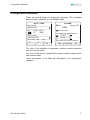
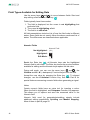
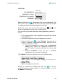
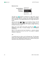


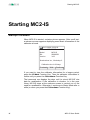
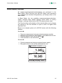


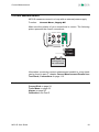
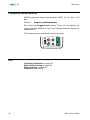
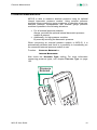


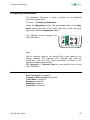


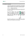


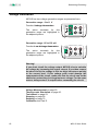


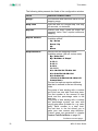
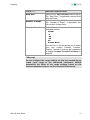


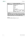
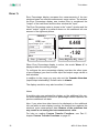

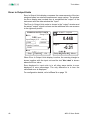

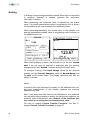
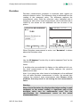


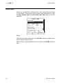


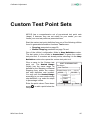

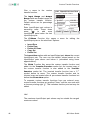


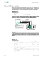
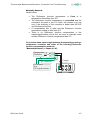
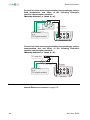

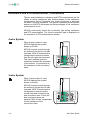
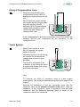


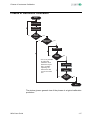


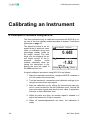

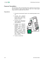


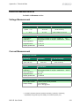
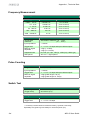
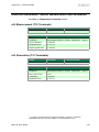
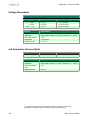

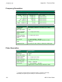
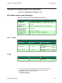
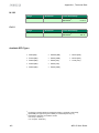


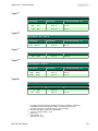
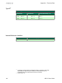
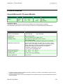
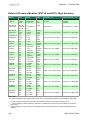
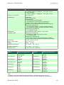


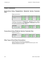


![CCM-LX [103-115108-02] for LW555](http://vs1.manualzilla.com/store/data/005891713_1-94f177118b12f5e24f93c1321ff002cf-150x150.png)