1
Fadal
Maintenance Manual
Section 16: Troubleshooting
Error Messages
Absolute Mode Required at N =
The CNC must be in the G90 (absolute) mode during all probe functions. Probe
function L9101 is programmed in the G91 (incremental) mode.
Amplifier Fault on Axis
This occurs at power on if the control does not detect an axis that should be
operational. This is often seen when the A axis is not in use and the dummy
termination plug has been installed. If the dummy termination plug is installed,
this message can be disregarded.
If this message appears for any of the other axes (X, Y, or Z), then power off to
check the motor overload relays. Power on and if the message appears again,
call the service department, noting the error message number.
Power off the machine before checking fuses, relays, and circuit breakers. The
motor overload relays can be recognized by their white reset buttons. They are
located in both control enclosures. The white button must be pressed to reset a
relay.
This message also appears when the EMERGENCY STOP button has been
pressed. The operator must release the EMERGENCY STOP button and press
the JOG button to reset the amplifiers. (Pressing in the EMERGENCY STOP
button disconnects the axis amplifiers. This is why this message appears when
the button is pressed.)
Arm Must Be Left
Before a pallet change can occur, the arm must be completely to the left with
the pallet on the table. The feed back on the arm is being read at this time.
Array Exceeds Allowable Number
This message will appear when the number on the array exceeds the expected
amount. This amount varies from variable to variable. For example, H(99) is
acceptable, H(102) is not.
March 2003
Section 16: Troubleshooting
509
Fadal
Maintenance Manual
ATC Failure
Check to see if the Z axis alignment was properly set at cold start. The
automatic tool changer has failed to respond to an M6 or the TC,1 command.
Try a power off and power on. If this does not help check the fuses.
The fuses F5, F6, F7, and F8 should be checked to see if they are burned out.
Circuit breakers 1 and 2 (if they are present) should be pressed to see if they
have been tripped.
Power off the machine before checking fuses, relays, and circuit breakers. If
this does not help, call the service department.
If this message appears with the turret in the extended position, it may be an
indication that the sensor for turret extension is faulty. Call the service
department.
ATC Turret Failure
Check to see if the Z axis alignment was properly set at cold start. Then check
to see if anything is caught between the sheet metal guard and the turret. If
not, this could be an indication that the sensor for turret rotation is faulty.
The fuses F5 and F6 should be checked to see if they are burned out. Circuit
breaker 2 (if it is present) should be pressed to see if it has been tripped.
Power off the machine before checking fuses, relays, and circuit breakers.
ATC Will Not Move to Position
Check to see if the Z axis alignment was properly set at cold start. An attempt is
made to make a tool change and something prevents the turret from going all
the way out to the spindle. Check the tracks that allow the turret to slide out to
the spindle. Sometimes chips stick to the track and prevent the rollers from
rolling on the track.
When this message appears use the command SETCS then the command HO
which will bring the tool to the Cold Start position. It is important to visually
check the axis indicator markers to see if they are aligned; if not, jog the table
until the markers are aligned. Use the command CS, then answer Yes (Y) to the
“move to home?” question. This will bring the tool to the part’s home position
and enable the operator to begin running the program in AUTO again.
It is also possible that the turret extended sensor is faulty.
Fuses F5, F6, F7, and F8 should be checked to see if they are burned out.
Circuit breakers 1 and 2 (if present) should be pressed to see if they have been
tripped.
510
Section 16: Troubleshooting
March 2003
Fadal
Maintenance Manual
Power off the machine before checking fuses, relays, and circuit breakers.
Attempted Division by Zero
In a macro statement, a division by zero was attempted.
Attempted SQR of a Negative Number
In a macro statement, a square of a negative number was attempted.
Attempt to Change CRC Side Without G40 at N =
This message will occur when attempting to switch from G41 to G42, or vice
versa, on a linear move. However, switching from one to the other is permitted
during circular interpolation.
Attempt to Change Tool While in CRC Mode, N =
This message occurs if a G41 or G42 is used in the program and a G40 code
does not appear before an M6 code. The G40 cannot be on the same line with
M6. An M6 will not cancel CRC.
Attempt to Switch Plane During CRC
G40 must be in effect (CRC must not be on) when changing planes. The default
plane selection is G17. If CRC is in effect and a code to change to another
plane (G17, G18, G19) is used, this message will appear in the block where the
plane selection was called. G40 must be in effect (CRC must not be on) when
changing planes.
Axis Controller Does Not Respond During Power Up Sequence
This an indication that there is a communication problem between the CPU
(1400) board and the axis controller (1010). Note error number and call the
service department.
Axis Controller Does Not Respond to NC
This an indication that there is a communication problem between the CPU
(1400) board and the axis controller (1010). Note error number and call the
service department.
Axis Data Transfer is Stalled
This message is the result of a data transfer problem between the 1030 card
and a 1010 card. This message does not represent a serious problem and
should only be reported to the service department if it is persistent. Please note
error number.
Axis Does Not Respond
This is possibly a problem with the 1010 card for the stated axis. Try a power
off and a power on. If this does not help, call the service department.
March 2003
Section 16: Troubleshooting
511
Fadal
Maintenance Manual
Axis Fault(s) as Follows
This appears when the EMERGENCY STOP button is pressed, a motor overload
relay is tripped, or the machine places itself into the Emergency Stop mode. If
any message or error number is presented on the screen, record this message
and number and report them, if needed, to the service department.
Release the EMERGENCY STOP button if necessary, then press the JOG button
which will reset the machine. If the machine does not reset, call the service
department.
If the EMERGENCY STOP button is not depressed, then power off the machine
and press the reset buttons of the motor overload relays to see if they are
tripped.
The motor overload relays can be recognized by their white reset buttons. They
are located in both control enclosures. The white button must be pressed to
reset a relay.
If the machine stalls for one reason or another, the control places itself into the
Emergency Stop mode. Press the JOG button and jog the tool out of the stalled
position.
An axis fault also occurs during an emergency stop because the control
removes the power to each of the axis servo amplifiers as a safety feature. The
control then analyzes the situation and, as a part of the report, shows a servo
amplifier fault, a result of having removed power to the amplifiers.
Axis Overflow
The axis controller detected an overflow situation. Power off the machine at the
main power switch wait ten seconds, and turn the power on again. If this
problem is persistent, call the service department.
Bad Circle OR Missing G at N
This can indicate an incorrect starting position for the circle, an incorrect
ending position, or an incorrect description of the arc center location relative to
the starting position of the circle.
This can also indicate that the circle is programmed in absolute or incremental
and the G90 or G91 codes are incorrect.
Bad Data or No Tool Dia.
This occurs when an H word (in format 1) or the D word (in format 2) is missing
in the program. When a program uses cutter radius compensation (CRC) or a
fixed subroutine, an H word or D word must be specified.
512
Section 16: Troubleshooting
March 2003
Fadal
Maintenance Manual
This also occurs when no diameter value is placed in the tool table when using
Fixed subroutines L94NN, L95NN,L9601, L9701, L9801, L9901. A DIAMETER
VALUE MUST BE USED.
When the fixed subroutine for engraving (L9201) is used, the Z depth and the
R2 variable must be included in the line. See the Users Manual for the correct
format. If the R0 variable is not specified, it is assumed as R0+0. If the R1
variable is not specified, it is assumed as R1+1.
Bad Fixture No.
Fixtures are numbered E1-E48. This message is displayed when a fixture offset
is programmed with a value greater than 48. Format 2: G54-G59 and E6-E48
are used.
Bad Interpolation Type at N
Check to see what type of move is intended for this block. G1, G2, and G3 are
the interpolation codes; G1 is for linear moves and G2 and G3 are for circular
moves.
Bad R Field
This occurs during input from the keyboard or through the RS-232 port (from
an offline computer) when the R0 was typed incorrectly. Example: If RO is typed
(R with the letter O) or R with no zero (0) is typed (R-.05 is accepted but not
R.05 or R+.05).
Correct the line in the CNC; or correct the line in the text editor and send the
program again.
Bad R1 Using L91 at N =
The R1 parameter is not present in the block containing L9101, or it is present
with an improper value. L9101 has 9 possible functions that are defined by the
R1 parameter; R1+1. through R1+9.
Bad T Word at N =
This message occurs during a SUM command. It indicates that the T word
value is larger than the tool changer capacity.
Bad Z or R0 in Canned Cycle Call, N =
This is a programming error due to the position of the R plane relative to the Z
axis position when initializing a fixed (canned) cycle.
Problem:
1) The R plane is described to be above the I plane.
March 2003
Section 16: Troubleshooting
513
Fadal
Maintenance Manual
2) The R plane is described to be below the final Z depth.
3) The final Z depth is described to end above the I or R planes.
Solution:
Check to see if the program has the correct positioning mode (G90 or G91),
and check for correct signs and decimal point placement.
Note: The H code might not be in the program.
Calculated Radius Error Of
This is a programming error possibly due to a G90 or G91 code missing, or
being in the wrong place. (EXAMPLE: Giving absolute positions while still in
incremental). Also, check the end point description, the beginning position,
and the arc center description (I, J, and K), or radius designation.
This message does not appear during the Auto mode. It appears when using
the SUM command (SU).
Cancel CRC Before G50.1 OR G51.1 AT N =
Before using CRC (G41, G42), mirror the desired axes (G51.1). Also, turn CRC
off (G40) before canceling mirror image (G50.1).
Cancel CRC Before N =
The control requires the G40 code to cancel cutter radius compensation before
the line number listed. See the cutter radius compensation section for
suggestions.
Cancel Z Axis Mirror Before Tool Change at N
The G50.1 code must appear on a separate line before the M6.
Cannot Return from Subprogram or Subroutine
Calling Line Cannot Be Found
This is a background editing error message. The line that called the
subprogram or subroutine was deleted or cannot be found.
Cannot Start Directly in a Subprog.
A mid program start must begin from the main program. If it is necessary to
start the program in a subroutine, the COPY command can be used to copy the
subroutine to the main program as many times as the subroutine will be
repeated. The programmer or operator can now do a mid program start to
where the subroutine was copied into the main program. After the part is
complete, delete the copied portion and run the program as before.
514
Section 16: Troubleshooting
March 2003
Fadal
Maintenance Manual
Another method to start the program in a subroutine is to use the AUTO
command. Enter AU,# (see AUTO command in the Operators Manual), where #
is a sequence number in the subroutine. The control will process the program
from the beginning of the program up to the number specified then start
execution of the program.
Char. Size or Depth Exceeds 2.5 In.
Characters that are higher than 2.5 inches cannot be engraved using the
Engraving mode (L9201).
Check Emergency Stop Switch and Motor Overload Relays
If the EMERGENCY STOP button (switch) is not pressed, it is necessary to check
the motor overload relays.
Power off the machine before checking fuses, relays, and circuit breakers. The
motor overload relays can be recognized by their white reset buttons. They are
located in both control enclosures. The white button must be pressed to reset a
relay.
Also, check the brake relay fuse (F17) to see if it is burned out. It is advised to
power off the machine when checking the fuses or motor overload relays.
Check Spindle Lube, Way Lube and Air Pressure
When this message is displayed, it is necessary to check the way lube level,
spindle oiler level, and the air pressure gauge. It is advised to check these oil
levels at least once a day.
Clear an Emergency Stop Condition
An emergency stop condition was invoked. To clear, press the JOG key. Wait 2
seconds for the amplifiers to be reset, then continue.
Command Error
This occurs because a SET (parameter) command was typed in improperly.
Refer to the Users Manual or use the menu of the control to help with any
command format. The following is a list of available SET commands: SETH,
SETX, SETY, SETZ, SETA, SETB, SETCS, SETTO, SETP.
Command Prohibited by the Key Lock
With the key lock in the horizontal position, editing commands (CH, CO, DE, IN)
cannot be used.
CRC Called With No Tool Assigned at N =
This happens when the programmer has turned CRC on without an H word in
the program.
March 2003
Section 16: Troubleshooting
515
Fadal
EXAMPLE:
Maintenance Manual
Format 1:
N1 G41
N2 H1
N1 H1
N2 G41
Format 2:
N1 H1
N2 G41
N1 H1 D1
N2 G41
This is incorrect.
This is correct for Format 1 only.
This is incorrect.
Diameter must be for Format 2 programming and
is acceptable for Format 1 programming.
This is a common error in one tool programs when the Z axis is set with the tool
at the gauge point. Assign an H word with no tool length offset (only a tool
diameter) in the tool table.
D or H Too Large
The control maintains a table of 99 tool diameters and 99 length offsets. The
control will only accept H words and D words up to 99.
Data Transfer Fault
For this error, it is important to note which axis the transfer fault is on and
report it to the service department. Please note the error message number.
There is a data transfer problem between the 1030 card (slot 8) and the 1010
card for the stated axis.
DNC Mode
This message appears after DNC is typed at the control. The VMC is then ready
for DNC operation and is waiting for CNC code from the RS-232 port.
Door Began to Close While Arm was Moving
This message will occur if the door begins to close during a pallet change. The
feedback of the door may need adjustment or there may have been a drop in
air pressure.
Do You Want to Move to the Last Home Position?
This is not an error message but it appears each time the operator uses the CS
command and a home position is established (SETH) in memory.
Do You Want to Reinitialize Memory?
This prompt is accessed by reinitializing the memory via the RI command. A ‘Y’
response zeroes the memory of the CNC.
WARNING
516
Section 16: Troubleshooting
March 2003
Fadal
Maintenance Manual
!
March 2003
All program data is deleted from memory. After the memory is reinitialized,
a cold start must be performed.
Section 16: Troubleshooting
517
Fadal
Maintenance Manual
Do You Want to Zero Tool Table?
This prompt is accessed by reinitializing the memory via the RI command. A ‘Y’
response zeroes the tool offset table.
!
WARNING
All tool diameter and length offsets are deleted from memory.
Do You Want to Zero Fixture Offsets?
This prompt is accessed by reinitializing the memory via the RI command. A ‘Y’
response zeroes the fixture offset table.
!
WARNING
All fixture offsets are deleted from memory.
Dry Run Option ___ is in Effect
The selected dry run option (1, 2, or 3) is displayed prior to automatic
execution. See the Users Manual or the Run Time Menu for the appropriate
option definition.
Duplicate Name
No two programs in the library can be identified by the same number. When
copying an existing program assign an unused number to the new, or copied
program. Use option 2 (display program numbers) of the PR menu to
determine which numbers have been used.
Duplicate or Bad Prog. Name
This will occur if a program is being input through the RS-232 port and the
program has an O word in the first line that is a duplicate of an existing number
in the program library. Use option 2 (display program numbers) of the PR menu
to determine which numbers have been used. Change the O word to one not
being used, or remove it. Then send the program out to the control again.
If the program currently active in memory has an O word in the first line, the
program will be moved into the program library when the new program is
transferred through the RS-232 port. If the program currently active does not
have an O word in the first line, the program will be deleted when the new
program is transferred.
Dwell, Hit Start to Interrupt
This message is displayed when a G04 (dwell) is executed by the CNC. You can
interrupt the dwell time and continue program execution by pressing the START
key.
518
Section 16: Troubleshooting
March 2003
Fadal
Maintenance Manual
E Word May Only Be Used With G0 or G1 N =
Fixture offsets cannot be on the same line with a circular move (G2, G3).
Emergency Stop - Take Appropriate Action
An emergency stop has occurred. If the emergency stop button is depressed,
turn it clockwise until it returns to its normal position. Press the JOG button and
the message WAIT 2 SECONDS, THE AXES ARE BEING RESET. If this message
persists, call the service department.
The appropriate action to take:
1) Release the EMERGENCY STOP button if it has been pressed.
4) Press the JOG button which resets the amplifiers if the problem has been
resolved.
5) Type HO and press ENTER, then after the waiting message appears press
START (see note).
6) The operator may now resume the running of the part.
Note: It is not necessary to move the axes to their Cold Start position or
establish the part home again unless the message, JOG AXES TO HOME
POSITIONS, THEN ENTER THE CS COMMAND appears.
Enter Again or Hit Manual to Exit
This message comes up when inserting program coding at the keyboard (using
the IN command) or when in Manual Data (MD) and Change (CH) mode. It is
referring to the line just typed. Something was not acceptable, for example the
letter O for the number zero (0) or anything else not correct. The control is still
on the line with the problem, so retype the entire line.
Enter Command SETP and Set the Machine Parameters
The SETP procedure will ask questions regarding the machine and certain
preferences. If any of the questions are not clear, call the service department
for help.
Enter Command MU to See the Menu
This happens when a command is typed incorrectly. Either it is an
unrecognizable command or a comma was omitted.
This message is only a suggestion. It is not necessary to go to the menu to use
a command. The menu is there to remind the operator of the command format.
March 2003
Section 16: Troubleshooting
519
Fadal
Maintenance Manual
Error
This message is a program input error. It is displayed when a program block
containing an error is transmitted to the CNC via the RS-232. It appears at the
time the error is received. Therefore, list the program at the control to display
the last block of code received. The following block of code in the program,
which was not received, is in error. This normally is caused by back to back
alpha characters, which must be separated by numeric characters. Also, a 0
could be typed as an O.
Error in User Program, ‘SUM’ to See Message
See the Operator Manual for instructions on using the SUM (SU) command.
This message will occur when the control lists an error message in the Auto
mode, and the operator persists in running the program by pressing the START
or AUTO button. This message will appear when the line in which the error
exists is at the top of the stack of lines to be executed.
Error N Word Exceeds 99999
This error occurs when the sequence number is larger than 99999. The
sequence number must be between .001 and 99999.
Error While Processing Block
This is an indication that there may be a problem with the CPU board.
1) Send the machine back to cold start alignment markers.
7) Power off the machine’s main power, wait 15 seconds and power on the
machine.
8) Cold start then run the program again.
If this error repeats:
1) Save all the programs and offset information currently in memory. Write
down the present home position.
9) Send the machine back to cold start alignment markers.
10) Use the command RI and answer Yes (Y) to all the questions.
If the above does not work please call the Service representative in your area.
Error(s) Reading Tape
While the control is inputting a tape or program with the TA command, error
option 2, this message appears after input is complete. If the TA command and
error option 1 is used (TA,0,1 or TA,1,1) the input of the program would have
been stopped if an error in the program is detected.
520
Section 16: Troubleshooting
March 2003
Fadal
Maintenance Manual
If errors are detected, list the program and look for missing line numbers to find
which lines the control did not accept. Use the IN command to insert the
missing lines where needed.
File Overflow
This message could mean that the program has too many G codes and M
codes on the same line.
It could also mean that during CRC, there were too many blocks that the control
had to look beyond for the next compensated move (comment lines, Z moves,
G code and M code lines, and dwells).
This message may also appear if a fixed cycle is in effect when attempting to
initiate cutter radius compensation.
Fixture Offset Out of Range
This message occurs when an E word value in the program exceeds 48 or in
Format 2 exceeds G54 - G59 or exceeds E1 - E48.
Fixture Offset Must Be Applied With G0 or G1
Fixture offsets cannot be applied on lines with circular interpolation (G2 or G3).
G28 and G29 Used With Cutter Radius COMP at SEQ
Before the control can execute the codes G28 or G29, the program must turn
CRC off (G40).
G31 Used With an Incompatible Word or Mode
Only G1, P and F are allowed with a G31. No other codes are supported. CRC,
mirror image, rotation and drill cycles are not allowed during the execution of a
G31 code.
G45-G48 & G52 are Not Allowed With Rotation. N =
Codes G45-G48 and G52 are incremental offsets. Rotation can only be used in
the Absolute mode. Therefore, these codes are not allowed.
G91.2 is Not Allowed in Format 1
The machine is in format 1 with the G91.2 code in the program. The G91.2
code can only be used in format 2. In format 1 you must remain in the
Incremental mode when G91.1 is coded.
G92 Cannot Be Used in CRC Mode. N =
The G92 code should be used in a line before CRC is turned on. The code G92
can only be used after a G40 (G40 is a default code).
March 2003
Section 16: Troubleshooting
521
Fadal
Maintenance Manual
G92 Must Be Only G Code in Block
There can be no other G codes in the line with a G92. The program does not
need to be in absolute (G90) to use the G92 code.
GNN is an Unsupported G Code At N
The G code displayed is not a supported code of the FADAL CNC 88.
Helical Move Too Short, N =
(See error message HELICAL RISE TOO STEEP)
Helical Radius Too Small, N =
(See error message HELICAL RISE TOO STEEP)
Helical Rise Too Steep, N =
The radius of the circle and the helical rise are radically different in length
(usually the rise is much longer in comparison to the radius).
Also, depending on the programmed feed rate, the control may or may not be
able to handle the situation. Reducing the feed rate in the program usually
helps.
I, J or K Must Be Specified at N =
This message is displayed when an X, Y, or Z is used with an R0 without a G2
or G3. Full circles must use the direction around the circle and either the I, J, or
K. See the circular interpolation section for more details.
Illegal O Word
This error occurs during program input via. the RS-232. The O word must have
a value of 1 through 9999. No other character or symbol is allowed.
Illegal G Code During G91.1 Mode at N =
This message appears when an illegal G code is programmed while in G91.1.
See the Users Manual for acceptable G codes.
Improper Use of Canned Subr.
This message may appear for the following reasons:
1) No tool diameter in the tool table.
11) The programmer omits a required R word from the subroutine.
12) The programmer does not cancel a fixed cycle with a G80, G28, G29, M6,
G49, or H0 before using a fixed subroutine, except for L93 (bolt hole).
13) Using L96 - L99, if R1 variable is equal to the radius of the tool. The R1
variable is used for the radius on the corner of the tool (fillet radius), not the
522
Section 16: Troubleshooting
March 2003
Fadal
Maintenance Manual
tool radius. For example, a 1.0 diameter end mill with a .125 corner radius,
the R1 variable will be R1+.125, and the tool diameter entered in the tool
table will be 1.0.
14) The G41 or the G42 code has not been canceled with a G40 before using a
fixed subroutine.
Inches Mode Required - Operator Must Set
The CNC is in the Metric mode (SETME), and the program has a G20 or G70
code to verify that the control is in the Inches mode. To run this program, the
operator must set the CNC to the Inches mode by entering the SETIN
command.
Incompatible G Codes at SEQ
Some codes, even though they are modal and from different groups (families),
are incompatible with one another. Break up the grouping of G codes on the
line by moving some of them to the line just before or after the line they are
presently on. This message is also displayed when any G code is on the line
with a G53.
EXAMPLE:
N20 G1 F20.
N21 G8 G41 X.5
The G41 and the G8 are incompatible.
Move the G8 to the line with the G1.
N20 G1 G8 F20.
This is correct.
N21 G41 X.5
Increment Divided By Two
If renumbering causes a line in the program to be greater than 99999, the
increment for renumbering is divided by two and renumbering is resumed.
All the lines or program blocks must have sequence numbers. The NU
command is used to renumber the lines in the program by the increment
specified in the first parameter. For example, entering NU,5 will renumber the
lines, incremented by five. If program is large, renumber by 1.
Increment Too Large
This occurs when the increment parameter of the program input (IN) command
causes the sequence numbers to exceed 99999 or a typing error in the
program has given a value too large. Example: X-123456789.
Increment Too Small
This alarm occurs when the increment parameter of the program input (IN)
command is less than .001 Example: IN, 0.00001
March 2003
Section 16: Troubleshooting
523
Fadal
Maintenance Manual
Input Xmodem Transmit Block Missed Error
This occurs when a packet has been missed or came out of order during
XModem transmission.
Jog Axes to Home Positions, Then Enter the CS Command
This message appears at power on. If the axes are at the Cold Start position
(machine home), enter the CS command. The operator needs only to jog the
axes if they are not at the Cold Start position.
This message also appears when the tool changer crashes and the AUTO
button is pushed or the MD command is used. However, the operator does not
have to jog to Cold Start. Use the SETCS command to reference the Cold Start
position, then enter HO to return the axes to home, and when the axes are back
at the Cold Start position, visually check, and enter the CS command.
SETP will also make this message appear. If the operator used the SETP
command at the part home, handle the situation in the same way as suggested
for a tool changer crash (see above).
Look Ahead Was Canceled By Operator
This indicates the NO LOOK AHEAD buffer option of the Run Time Menu has
been selected. The CNC processes only one block at a time, while displaying
only two blocks of the program on the screen. This option can be selected or
canceled using the Run Time Menu by typing MU in the Automatic mode.
M, S, T Lockout is in Effect
This message indicates the M function, Spindle, and Tool change lockout
option of the Run Time Menu has been selected. In this mode, M function,
Spindle or Tool Change commands will not be performed during Dry Run. This
option can be selected or canceled using the Run Time Menu by typing MU in
the Automatic mode.
M Function Too Large at N =
M functions cannot exceed a 2 digit value. See the Users Manual or the menu
(MU) for a list of the accepted M functions.
Main Prog. Not Found
This is a programming error. There are subroutines written in the beginning of
the program without an M30. M30 is used to separate the subroutines from the
main program. Insert the M30 in the proper place. See the Users Manual for
the accepted format for subroutines.
The M30 code on the first line of the program and a subroutine heading (L100)
on the next line will also cause this error message to appear.
524
Section 16: Troubleshooting
March 2003
Fadal
Maintenance Manual
N1 O1 (START OF PROGRAM
N2 (ACCEPTABLE PROGRAM EXAMPLE)
N3 L100 (SUB #1)
N4 X1.
N5 *
N6 L200(SUB #2)
N7 L105
N8 M46
N9 X-5.Y-1.
N10 M47
N11 *
N12 L300 (SUB #3)
N13 G91
N14 L204
N15 L104
N16 G90
N17 *
N18 M17 ——— This ends the last subroutine.
N19 M30 ——— This separates the subsection from the main program.
N20 *
N21 (MAIN PROGRAM)
Memory Error, Reload Program
This is a memory error. Turn the machine’s main power off. Then power on and
reload the program. If this does not work, save all the programs in the memory
(PU,3) and use the RI command, answering Yes (Y) to all the questions. After
using the RI command, load the programs back into the control.
Memory Error, Respond With Y to Delete Bad Blocks
There is a possible hardware problem when this message appears.
If the operator answers Yes (Y) to this question, the control may delete some of
the program in memory. Answer Yes (Y) only if the program in memory can be
replaced (if the program is stored on paper tape or on computer disk). Answer
No (N) if the program needs to be saved.
Turn the machine’s main power off. Then power on and reload the program. If
this does not work, save all the programs in the memory (PU,3) and use the RI
command, answering Yes (Y) to all the questions. After using the RI command,
load the programs back into the control.
If this does not help, call the service department.
March 2003
Section 16: Troubleshooting
525
Fadal
Maintenance Manual
Metric Mode Required - Operator Must Set
The control, at power on, is in the Inches mode. The Metric mode must be
turned on by using the SETME command.
This message will appear if the G21 or G71 code is present in the program to
verify that the Metric mode has been turned on by the operator.
Motor Overload
This is an indication that something has stalled or overheated a motor, and is
associated with an emergency stop (see EMERGENCY STOP).
Move Exceeds Axis Limit at N =
Check Program and Tool or Fixture Offsets
The most common reason this message appears is because of either a missing
or an extra G90 or G91 code. This message will appear only when the control is
in the Auto mode or Manual Data (MD) mode. This message will not appear in
the Sum mode (SU).
When the control is executing the program, processing of the program is ahead
of the current line that is being executed. If, while processing the program, the
control detects an over travel situation, execution of the program will stop
immediately.
The setup person may have to consider moving the fixture to another location
on the table. The program may be correct but the fixture is set up incorrectly.
The programmer can provide information to the setup person, indicating how
close to the axis limits the fixture can be located.
Move Turret to Tool 1 and Enter SETTO Command
When this happens, the head will be above the tools in the turret, with the turret
ready for loading. Move the turret using the turret CW or CCW buttons so that
the tool designated to be tool #1 is under the spindle, and remove tool #1 from
the turret. Press the JOG button. The head will stay where it is (4” above the Z
axis CS position), and the turret will move back to its home position. Now use
the command SETTO to establish this turret position as #1. Use the HO
command or jog the head down to the Z axis CS position. Next use the
command TC,1 to reopen the turret. Replace tool #1 in the turret and press the
MANUAL button to bring the head down over tool #1.
Next Entry is Out of Range
This message is displayed by entering pitch error compensation for the ball
screw when an entry exceeds the maximum allowable difference of 9 (See
Survey command in the Axis Drive Systems Section). For example, if an entry
is 15 and the next consecutive entry is 0, the difference is greater than 9.
526
Section 16: Troubleshooting
March 2003
Fadal
Maintenance Manual
No Angle, the Points Are the Same
The calculated angle, of either function 3 or 4 of L9101, is the same as the
expected angle.
No Memory Available for New Program
When this occurs, the operator will have to remove (delete) as many programs
as necessary from the program library to input another program from the RS232 port.
The standard memory capacity is an equivalent of 277 feet of paper tape.
FADAL distributors have a memory expansion board available that increases
the memory capacity to 1205 feet of paper tape.
No Other Words Allowed With O Word
If program coding is used on the first line of the program along with the O word,
this message appears. A comment is allowed with an O word and is used to
identify each program in the library. The first sixteen characters of this
comment are shown when the program library menu displays the programs in
memory.
EXAMPLE:
N1 O1 G0 G90 (P/N 1234) — This line is incorrect.
N1 O1 (P/N 1234) — This line is correct.
N2 G0 G90
No Parameters or Parameters Corrupted
Machine Defaults Used
This message occurs most commonly after the memory has been zeroed from
the DI diagnostics mode. This will also occur if there is a memory error. Enter
the machine parameters with the SETP command. The parameters to use are
usually found recorded on a check off sheet on the inside door of the pendant.
No Response From Axis
This happens when powering on the machine and the CPU (1400) does not get
a response from the axis controller (1010).
If this message appears for the X, Y, Z, A, or B axes, power the machine’s main
power off and then on again. If this does not help, call the service department.
No Touch or Incompleted Point at N =
The move that causes the probe to touch the part was completed without a
touch. Increase the length of the move so that the probe touches. Also, you
must activate the selected probe by coding an M64 for an MP8 probe, or an
M65 for a TS20.
Note Error Then Hit Manual
March 2003
Section 16: Troubleshooting
527
Fadal
Maintenance Manual
When the programmer is inputting a program through the RS-232 port (using
the command TA,1,0 or TA,1,1), the input will be terminated if the control
detects a bad programming word (EXAMPLE: O for 0, or double letters (XX1.5),
etc.).
The programmer will have to edit the program at the computer or Teletype
before inputting the program again.
The control will ignore all errors in the program and continue input by using the
error option 2, with the TA command (EXAMPLE: TA,1,2). An error count is
given at the end of transmission. If there were errors detected, list the program
to find missing line numbers. If the lines are numbered in sequence before
transmission of the program, look for the numbers that are out of sequence.
After the numbers have been located use the IN command to insert the
missing lines.
Number Out of Range
This message appears when a number of twelve digits or greater is typed in.
This error may be detected by the machine after making a calculation. The
calculated number may be out of range. Macro calculation less than .0001.
Offset Entry Error
This message is displayed using the Utility (UT) command, by pressing the
MANUAL key when the CNC prompts you for a tool diameter. It is also
displayed by entering a diameter value that is too large.
Only Block Skip Allowed With Macro
The only non macro command allowed with a macro line is the block skip
character.
Only M3, M4 & M5 Are Allowed With M6 at N =
This message appears when the M6 is coded with an M function other than an
M3, M4 or M5. The unacceptable M function must be moved to another line.
Only Z, L, R & F Words Allowed
This message appears when the programmer uses the fixed subroutine L9201
for engraving, and has programmed other words in the line with the L9201
other than Z, L, R, and F.
Orientation Failure
Visually check the air pressure, it must be between 80 and 90 PSI. If this
problem persists call the service department.
528
Section 16: Troubleshooting
March 2003
Fadal
Maintenance Manual
Out of File Space, a File Compression is Being Tried
This message informs the programmer that the memory of the control is
almost full. It usually is displayed when editing the active program in memory,
or during program input via the RS-232. This does not destroy any portion of
the program. A file compression organizes the memory so that unused portions
are made available. The NE command will perform a file compression before
prompting you with a (Y or N) to delete the current program. Also, a file
compression is performed by deleting the current program using option 5 from
the PR menu.
It is always best to retry the command that caused this message to appear.
After the compression, the command will often work the second time.
If unwanted programs are stored in the program library, remove them to create
more room in memory. If there is only one program in memory, try to reduce
the size of the program by removing unnecessary comments and making full
use of all modal codes. Create subroutines for repetitive portions of the
program wherever possible. The program may have to be broken up into
separate operations.
The standard memory capacity is an equivalent of 277 feet of paper tape.
FADAL distributors have a memory expansion board available that increases
the memory capacity to 1205 feet of paper tape.
O Word Out of Range
This occurs using the program input (IN) command when typing an O word
greater than 4 digits. O words must be an integer of 1 through 9999.
Pallet Disabled in Parameters
This message occurs when a pallet changer command or code is used and the
SETP parameters indicate no pallet changer exists on the machine.
Pallet in Storage
This message occurs when there is an attempt to store a pallet where a pallet
already is stored.
Pallet Not Fully Stored
This message occurs when the time to store a pallet exceeds the allotted time.
The feedback on the arm may need to be adjusted. Call the service department
for assistance.
March 2003
Section 16: Troubleshooting
529
Fadal
Maintenance Manual
Pallet Must Be Clamped
This message occurs when both pallets are in storage and a command is give
to make a pallet change. One of the pallets must be loaded and clamped on
the table before a pallet change can occur. The feedbacks for pallet loaded and
pallet stored are being read at this time.
Parameter Error
After a command is entered and a comma is typed, the control is expecting a
parameter. If a parameter is not typed before pressing the ENTER button, this
error message appears.
EXAMPLE:
AU, — This is a parameter error.
Note: If the operator is not using a parameter, for instance, the second and
third out of a possible four, the parameters can be omitted when the fourth
parameter is typed in.
EXAMPLE:
AU,50,,,1 — This is acceptable.
Also if the DE command is used to delete a line that does not exist, or the CO
command is used to copy lines that do not exist, this message appears.
Parity Error
This message appears during input through the RS-232 port and is caused by
several factors.
1) Unshielded cable is used, and the cable is subject to electrical noise.
15) The baud rate is too fast for the length of cable used.
16) There is a failure in the RS-232 port (hardware problem).
17) There may be a problem with the computer that is sending the program.
Parity Error During DNC
This occurs during DNC transmission of data. (See the error message PARITY
ERROR)
530
Section 16: Troubleshooting
March 2003
Fadal
Maintenance Manual
Please Put an O Word at the First of the Current Program
The Following Programs Are in Memory
To use the PR command, the active program must have an O word and a
number in the first line. The number must be different than the other numbers
in the program library. This is why it lists the other programs in memory.
EXAMPLE:
N.1 O43 (P/N 34-765)
N1 G0 G90 S10000 M3
Here, a line was inserted
before N1 using the command: IN,.1
A comment can be added to the line with the O word. These comments help
identify the program.
Points Are on Same Line at N =
The 3 touch points of L9101 function 1, are on the same line. Check the
program for positioning errors.
Possible Probe Over Travel
During the UT command, this error occurs for two cases. The first is when the Z
axis home position is set below the Cold Start position and the tool change is
made to the Probe. The second is when there is a positive offset value used,
and the tool change is made to the Probe.
Position Limit
This message will occur when the program has instructed the tool to move out
beyond the axis limits. When the tool moves beyond the axis limit the CNC
issues an emergency stop.
The machine will stop at the line which caused the over travel.
Press Y to Keep This Position
Press N to Return to Last Position
These messages appear after jogging while in Slide Hold or Single Step
modes. See the Users Manual for the proper application of the Jog Away
feature.
Probe Test = Failure
Testing the probe by using the Utility (UT) command failed. Verify that the probe
was properly interfaced. If an MP8 or MP9 is being tested, be sure the 9 volt
battery has a charge. Also remove any obstructions between the probe
(transmitter) and the collector unit (receiver).
Problem Positioning Slides to Zero
This error only occurs during Cold Start. When the Glass Slides are not aligned
close enough to the indicators during Cold Start. Place the machine in Jog and
manually align the Cold Start indicators more accurately.
March 2003
Section 16: Troubleshooting
531
Fadal
Maintenance Manual
Program Does Not Exist
Retry or Hit Manual to Exit
This happens when the selected program number does not exist in the
program library. Enter a program number that does exist, or press the MANUAL
button, and then use the PR command again to display the programs that are
stored in memory (option 2).
The programmer may have put an O-1 or an O.1 as a program number. The
number will show up when the programs are displayed in the library but the
control will not be able to retrieve the program. If the operator uses the PU,3
command and presses the EMERGENCY STOP button when the lost program is
being displayed on the screen, that program is now active in memory and can
be edited. Delete the bad O word, from O-1 or O.1 (which appears as 1000
when it is listed in PR) to O1.
Program Not Found
This message is displayed when the PA command is used to display the active
program, and no program is active. Use the PR command to activate the
desired program stored in memory.
Program Block Not Found
This message is displayed when the LI command is used to list selected blocks
of the active program, and the selected blocks are not found or the program is
not active. View the program by using the PA command.
P Word Too Large
The P word for referencing a line number using M99 is too large of a value. Line
numbers can not exceed 99,999.
Reset the Emergency Stop Switch
The EMERGENCY STOP button has been pushed. Turn the button clockwise
until it is released and then push JOG.
Resolver Fault or Scale Error
This message may occur in three cases as follows:
1) A failure of the resolver.
18) An axis runaway during power on.
19) A large Scale or Motor error, indicating a possible scale failure.
!
532
IMPORTANT
Report this to the service department when this message appears. Do not run
the machine when this message appears.
Section 16: Troubleshooting
March 2003
Fadal
Maintenance Manual
Rails Not Aligned
This message occurs when the rails for the pallet changer are not aligned or
the feedback switches need adjustment. Call service department for
adjustment.
Return Pallet to the Load Position
This message occurs when a pallet change is attempted and the other pallet is
away from the load position. The operator must slide the pallet into the load
position before the other pallet on the table can be changed. The feedback
from the pallet loaded and pallet stored are being read at this time.
Rotary Axis Move Too Long. N =
The maximum incremental rotary move for one block is 1080.00 degrees. If it
is necessary to go further, break up the move into several blocks.
RS-232 Error During DNC
This error only occurs during DNC operations. It may occur while using 9600
baud to DNC. Slow the baud rate.
It may also indicate line noise or the possibility of dropped characters. These
would indicate a possible problem with the RS-232 cable or the
communications port. Check the cable and communications port and retry
DNC.
A failure of the CPU may cause this error also. If the above corrections are
unsuccessful, contact the maintenance department.
Scale Error
A scale error has been detected. The LEDs in the scale interface box in the
back of the machine will indicate which axis gave the error. Call the service
department.
See Menu for New CD Format
The CD command is different for some versions of software. See the menu for
these changes.
Sequence Number Too Large
This occurs using the Program Input (IN) command when the ‘From’ parameter
is specified greater than the maximum allowable number. Sequence numbers
can not exceed 99,999.
Sequence Number Too Small
This occurs using the Program Input (IN) command when the ‘From’ parameter
is less than the minimum allowable number. Sequence numbers can not be
less than .001.
March 2003
Section 16: Troubleshooting
533
Fadal
Maintenance Manual
Servo Amplifier Fault
This message appears when the EMERGENCY STOP button is pressed. The
operator must pull the button out (for ‘85 and older models) or turn it clockwise
(for ‘86 to present models) and then press the JOG button to reset the
amplifiers. If the amplifiers do not reset, call the service department.
Single Step
This message identifies the control is in the Single Step mode. Should the
green START button be pressed when in this mode, the following program
block is executed.
The feed rate potentiometer affects all axis motion.
At the end of each block, the operator can press the JOG button and jog away
from the current position without aborting the operation. Program execution
can be continued at the new location, or the axes can be returned to the
position at which the Jog function was initiated.
To exit single step, press the AUTO button for continuous block execution.
Slide Hold
Pressing the SLIDE HOLD button stops all axis motion. The distance to finish
the move is presented under the blinking SLIDE HOLD message.
It is possible to press the JOG button and jog away from the current position
while in the Slide Hold mode without aborting the operation. Program execution
can be continued at the new location, or the axes can be returned to the
position at which the Jog function was initiated.
To exit from the Slide Hold mode, the operator must press the START button, if
in single step, or press the AUTO button for continuous block execution.
Spindle Controller Does Not Respond
Please note error number and see list at the end of this chapter. This simply
could be a problem that occurs when the operator is powering on the machine.
Turn the machine’s main power off. Press the motor overload relay button, and
then power on again. If this does not help call the service department with the
error message and number.
The motor overload relays can be recognized by their white reset buttons. They
are located in both control enclosures. The white button must be pressed to
reset a relay. Call service department first.
534
Section 16: Troubleshooting
March 2003
Fadal
Maintenance Manual
Spindle Controller or Driver Fault
Please note error number and see list of Emergency Stop Error Messages at
the end of this chapter. This message is displayed if the spindle was
commanded to turn on after an emergency stop without pressing the JOG
button to reset the amplifiers.
If this message appears when not in the Emergency Stop mode, please take
these steps to help the service department analyze the problem:
1) Look at the air pressure gauge and write down the current air pressure (do
not change it at the machine!)
20) Check to see if the belts are on the pulleys.
21) Do not turn the power off.
22) Call the service department and report this problem (while the machine is
on).
Spindle Controller Software Update is Required
The current software module (1610) detected spindle software that was not
compatible. Call the service department.
Spindle Driver Fault
This is the result of the air pressure being too low while the spindle is on. Air
pressure should be set between 80 and 90 PSI. Visually check the air pressure
and start the program over again. If the air pressure is not the problem, power
off the machine and check the motor overload relays to see if they have been
tripped.
The motor overload relays can be recognized by their white reset buttons. They
are located in both control enclosures. The white button must be pressed to
reset a relay.
Spindle Failure While Tapping
If the spindle stops while in G74, G75 or G84 modes, this message will appear.
Problems such as a dull tap, undersized hole, poor tapping lubricant or a
shallow hole must be eliminated. The programmer may want to consider
thread milling as an alternative to tapping. Call the service department if this is
persistent.
March 2003
Section 16: Troubleshooting
535
Fadal
Maintenance Manual
Spindle Failure During Reversal
This will occur when an M3 and an M4 are in the same line. If the spindle stops
while in G74, G75 or G84 modes, this message will appear. Problems such as
a dull tap, undersized hole, poor tapping lubricant or a shallow hole must be
eliminated. The programmer may want to consider thread milling as an
alternative to tapping. Call the service department if this is persistent.
Spindle Has Failed to Turn On
Either the Hall Effect Switch on top of the spindle pulley has not recognized that
the spindle is turning, or the spindle actually has not turned on and there is
another problem. Call the service department.
Spindle Fault Line
The spindle inverter has detected a fault. See the fault number on the inverter
and report this to the service department.
Spindle Motor Temperature Fault
Check to see if the spindle fan is on. If it is not, turn machine’s main power off
and check the fuse for the spindle fan (F24). Allow time for the spindle motor to
cool down and attempt to run the machine again. If this message persists, call
the service department.
Spindle Would Not Stop
The spindle would not stop in the designated amount of time (12 seconds). If
this message is persistent, call the service department.
Stack Overflow
This message should be reported to the service department. It is caused by
excessive stacking of keyboard commands.
Subr. Does Not Exist
This message indicates that a subroutine was called that is not in the
subroutine section of the program. Check to make sure that the subroutines
were numbered properly.
This message also appears if the G66 code is used on a line that does not have
a subroutine call on it.
536
Section 16: Troubleshooting
March 2003
Fadal
Maintenance Manual
Subr. Nesting Error
This is a message that occurs when a subroutine heading (L0100) is entered
after the M30 code. This message will also occur if a Fixed Cycle is still active
(use a G80 to cancel) or G68 (rotation) is still active when a tool change or end
of program is coded (use a G69 to cancel).
EXAMPLE:
N20 M17
N21 M30
N22 L200
This is not permitted after an M30.
Tape Input Terminated
This message reports to the operator that the tape or program input process is
complete.
Tape is Good
When verifying a punched tape, this message appears if the tape is accepted.
This message also appears if no errors are detected in transmission when the
TA command is used.
Temperature Fault
For any temperature fault, the operator must check the cooling fans; if they are
not operational, turn the machine’s main power off and check the fan fuses
(F23, F24, F27, and F28).
If this message is persistent, call the service department.
Temporary Conflict With Auto
This message occurs when background editing is being used. The edit just
made is in the area where auto is currently executing from. The change will be
made when auto is out of that area.
The Axis Controller is Not a 1010-4
(See Survey in the Axis Drive Systems Section)
The Survey Contains Errors, Please Review
(See Survey in the Axis Drive Systems Section)
The Survey Was Not Written to the Axis Controller
(See Survey in the Axis Drive Systems Section)
There is No Survey
(See Survey in the Axis Drive Systems Section)
March 2003
Section 16: Troubleshooting
537
Fadal
Maintenance Manual
Thread Lead Not Specified at N =
Fixed cycles G74, G75 and G84 need a Q word in the line that represents the
decimal thread lead of the tap (see the Users Manual for the proper format). If
the Q word is omitted this message will appear.
If the programmer uses the fixed cycles G74, G75 or G84 and does not cancel
the cycle with any of the following codes: M6, G28, G29, G49, G80, H0, this
message will appear at the next Z move.
Too Many Blocks For Gap
This happens when the CO (copy) command is used and there are too many
lines being copied between existing lines in the program.
Use the NU (renumber) command and copy again, now that the program is
renumbered.
Too Many M Functions at N =
This error occurs when another M function is coded with the M17 or M30.
These two codes must be the only M function on the line.
Too Many Consecutive Non Motion Blocks
This error message appears if a program contains over sixteen consecutive
comment blocks (with no program coding in the lines).
A solution to this is to put coding between the comment lines or put comments
on lines with program coding. This way the program can have comments on
every line.
Comment blocks in the beginning of the program can be placed in an unused
subroutine. This way the control never reads the lines when executing the
program, but the operator can list the program and read the comment lines.
Too Many Parameters
Commands have associated with them a certain number of parameters. If
more parameters are typed in than allowed, this message appears.
EXAMPLE:
AU,50,,,1, or AU,50,,,3,1
Refer to the Users Manual, or the Menu (MU) on the control for the correct
format of each command.
Too Many Subr. Calls
Nesting can only be seven deep. If the program goes further than seven deep,
this message appears.
538
Section 16: Troubleshooting
March 2003
Fadal
Maintenance Manual
Tool Breakage Detection = Failure at N =
When the TS-20 touch probe is used for tool breakage detection, this error
indicates the program line that the broken tool is detected at. Replace the tool
and continue the program.
Tool Diameter Too Large at N =
This is displayed in cutter radius compensation when the programmed move is
smaller than the radius of the cutter.
1) Check the tool diameter entered in the tool table to see if it was entered
correctly.
23) Check the program to see if it contains any typographical errors.
24) If the intention was to make a rough pass using a larger tool diameter than
the finish pass tool diameter, the smallest programmed inside radius, on
the part, should be as big as the tool radius (half the tool diameter) entered
for the roughing pass.
25) Check the math work to see if it is correct, and was transferred correctly to
the program.
When debugging a program that uses cutter radius compensation use a zero
diameter in the tool table when running the program or when using the SUM
command for the first time. Then put the tool diameter in the tool table and try
it again. This will make the debugging process easier.
Tool Offset Not Allowed During Z Mirror
If mirroring the Z axis is desired, first call up the tool length offset, then code
the G51.1 Z0. The H word must be on a line in the program before the G51.1
Z0.
Tool NN is in the Spindle
Identifies the current tool that is in the spindle. This is displayed when entering
the program execution (AU) and the Manual Data Input (MD) modes, and is
also listed in the tool table display (DT).
Tool Number Too High
The starting tool number of the utility (UT) tool setting cycle must not exceed
that of the tool changer capacity.
Tool Turret Location is Not Set
Rotate the tool turret so that tool #1 is adjacent to the spindle and then type
SETTO.
Transfer Error, Please Retry
March 2003
Section 16: Troubleshooting
539
Fadal
Maintenance Manual
(See Survey command in Maintenance Manual)
Trouble Reading the External Slide Hold Switch
The feedback from the external slide hold switches is erratic or inconsistent.
This is an indication that the external slide hold switch system is faulty. Call the
service department.
Type A Y To Ignore, Or Turn Power Off And Then On Again
This error message appears only after the message AXIS CONTROLLER DOES
NOT RESPOND DURING POWER UP SEQUENCE.
This is an indication that there is a communication problem between the CPU
and the axis controller. Call the service department.
Undefined Macro Error
This message will appear when situations during a macro execution cause the
system to fail, but there is no specific error or message associated to the
situation.
Wait 2 Sec., The Axis Drivers Are Being Reset
This message occurs when the JOG key is pressed after an axis fault. The
control returns to the Command mode after 2 seconds. The axis drivers are
reset and the machine can continue normal operation.
Waiting
In the Waiting mode, the operator has the choice of pressing either the START
or AUTO button to execute automatic motion. Or, the operator can press the
MANUAL button to exit to the Command mode.
Waiting On Air Valve
When this occurs, the control is waiting on a signal from one of the air valves
indicating that the valve has completed its job - usually air pressure to the
machine has dropped below 80 PSI.
If this message persists, call the service department.
Warning Possible Gouge at N =
Generally caused by math errors in the program. The CNC has processed a
move that possibly could cause the cutting tool to damage the part. The error
usually is not large enough to make any noticeable difference on the machined
part. Therefore, only a warning is displayed. If there is a noticeable difference,
review your program math.
Way Lube Pressure Switch Failure
Check the way lube oil level if this message appears.
540
Section 16: Troubleshooting
March 2003
Fadal
Maintenance Manual
Writing Error, Wait 2 Min. and Retry
(See Survey in the Axis Drive Systems Section.)
X, Y, or Z Move Must Be Specified at N =
Probe function #1 (L9101) has been programmed without an axis specified for
the given plane. For example, if probing is to be used in the XY plane (G17), X
and/or Y must be programmed in the same block as L9101 R1+1. Z can be
used if in the ZX (G18) or YZ (G19) plane.
You Cannot Delete the Program That is Currently Active
To delete a program in memory, it must be in the library. Use the PR command
and switch the program currently in memory with a program in the library. The
program can then be deleted. If there are not any programs in the library, use
option 3 to start a new program. This will put the currently active program in
the library and the program can then be deleted.
Or just simply use the DE command and delete starting from the first block in
the program to the last.
You Have a Version Upgrade or Memory Has Been Corrupted
Memory Needs to Be Zeroed
This occurs when the control detects that a new module has been inserted. See
the Maintenance Manual for proper zeroing procedures. This may also occur
because of a memory error and the memory needs zeroing.
You Must Enter the Backlash Table
The CNC does not have a valid backlash table. Enter the backlash for each axis
by using the BL command. The backlash set at the factory is documented on
the inside surface of the pendant door.
The backlash information is retained by the battery backed memory card. If this
message appears again, after the BL command has been used, call the service
department.
Your Version of CNCMAIN Needs to Be Updated
The control has detected an incompatibility with the CNC memory manager
software on the 32MP pendant. Call the service department for an update.
Z, Q, or F Missing in Canned Cycle Call, N =
See the Users Manual in the fixed cycle section for the proper format for each
fixed cycle.
March 2003
Section 16: Troubleshooting
541
Fadal
Maintenance Manual
Z & M6 Lockout is in Effect
This message indicates the Z axis and Tool Change Lockout option of the Run
Time Menu has been selected. In this mode, Z axis movement and tool change
commands will not be performed during Dry Run. This option can be selected
or canceled by using the Run Time Menu.
Z Axis Must Be at Cold Start for TC,1
Check to see if the Z axis alignment was properly set at cold start. The operator
cannot use the TC,1 command unless the Z axis is at the Z axis CS position.
Use the HO command or jog the axis to the Cold Start (Z0).
If the SETZ command has been used, first use the HO command to bring all
axes home, then enter the SETCS command. Jog the Z axis to Z0 and then use
the command SETH so the X and Y home position is not lost. The TC,1
command can now be used to open the tool changer. If necessary return the Z
axis to the previous setting and use the SETZ command.
(See the error message JOG AXES TO HOME POSITIONS if the tool changer
crashes).
Emergency Error
Codes
Error Numbers From
the Axis or Spindle
Controller
Error numbers help discern the location of the problem the axis or spindle is
reporting. The error number will follow a message to call the service
department and report the error number on the screen to correct the problem.
[ 1 ] NO MOTOR FEEDBACK
This error appears during power up, when no motor feedback (either resolver
or encoder) is detected by the axis controller.
[ 2 ] ENCODER NOT RESPONDING
This error appears during the rigid tap operation. If the encoder feedback is
interrupted during the spindle operation then the spindle operation is halted.
[ 3 ] LOGIC JUMPER INCORRECT OR COMMAND SIGNAL MISSING OR
MOTOR-TACH CONNECTION INCORRECT
This error appears during power up. An incorrect motor—tach—jumper
configuration or failed component may cause the axis to run away in the
opposite direction of the command signal. Axis operation is halted.
[ 4 ] ENCODER IS NOT 1024 LINE
This error appears during power up, and only applies to axes with
encoder(1024 line) as motor feedback. The axis controller will count the
encoder lines in one revolution of the screw and compare it to the expected
count of 1024
542
Section 16: Troubleshooting
March 2003
Fadal
Maintenance Manual
[ 5 ] NO INDEX MARK DETECTED
This error appears during the cold start process, if the index mark of the axis
primary feedback device, encoder or scale, is not detected.
[ 6 ] SWITCH 1 DISABLED
Currently not used.
[ 7 ] RIGID TAP PRECYCLE ENCODER COUNT PROBLEM
This error appears during the rigid tap precycle process, when the spindle
feedback is not within tolerance.
[ 8 ] SPINDLE MAGNET NOT DETECTED OR SPINDLE NOT TURNING
This error appears during spindle operation if the spindle magnet is not
detected for any period longer than 3 seconds.
[ 9 ] SPINDLE FAULT LINE DOWN
This error appears any time the axis card no longer detects the fault line signal
from the inverter, or the signal strength has dropped below 10V, indicating a
possible inverter fault.
[ 10 ] ENCODER AND MAGNET NOT RESPONDING OR SPINDLE NOT
TURNING
This error appears during spindle operation if both the encoder feedback and
the spindle magnet are not detected for any period longer than 3 seconds.
[ 11 ] FOLLOWING ERROR CANNOT BE SCALED FOR COMMAND SIGNAL
This error appears when the signal strength of the following error, after scaling,
exceeds the maximum allowable command signal.
[ 12 ] MOTOR OVERLOAD — STEP COMMAND CHECKSUM ERROR
This error appears at the completion of a move, when the actual move by the
axis controller is not equal to the move commanded by the CPU.
[ 13 ] MOTOR OVERLOAD — FOLLOWING ERROR > OVERLOAD FACTOR
This error appears when the following error exceeds the overload factor, which
is a user-defined parameter that sets, in motor turns, the maximum allowable
following error for the axis operation.
[ 14 ] MOVE TRANSFER FAULT — BUFFER INDICATOR NOT SET
This error appears prior to executing the first step command of a move
command, if the flag indicating completion of the move transfer process is not
set.
March 2003
Section 16: Troubleshooting
543
Fadal
Maintenance Manual
[ 15 ] TIME OUT ERROR — RIGID TAP PRECYCLE TEST
This error appears during the rigid tap precycle process, if the spindle rotation
is interrupted or the spindle magnet is not detected within the allowable time.
[ 16 ] TIME OUT ERROR — RESOLVER RESPONSE
This error appears any time the resolver “zero-crossing” pulse is not detected
within the allowable time (4-10 milliseconds). This pulse is hardwaregenerated every 1 millisecond.
[ 17 ] BAD READING ON RESOLVER PORT
This error appears if the value of resolver “counts”, read from the resolver port
when the “zero-crossing” pulse is detected, is too large, indicating possible
failure of the resolver cables, 1010-4 card, or the resolver itself. Also caused
by severe motor vibrations.
[ 18 ] AMPLIFIER FAULT LINE DOWN
This error appears any time the axis card no longer detects the fault line signal
from the amplifier, or the signal strength has dropped below 10V, at least 5V
indicating a possible amplifier fault.
[ 19 ] STACK OVERFLOW — OVERLOADED WITH STEP COMMAND
This error appears if the stack on the axis card, used to store CPU commands
until they have been serviced, overflows.
[ 20 ] MOVE TRANSFER FAULT — MOVE SETUP INCOMPLETE
This error appears when an axis move command is not properly transferred to
the axis card, as indicated by a checksum comparison between what the CPU
sent and what the axis card received.
[ 21 ] UNEXPECTED INTERRUPT
This error appears if the interrupt currently being processed is not an expected
interrupt, and therefore cannot be serviced, indicating possible failure of the
1010-4, 1030, or main CPU.
[ 22 ] BAD SCALE READING
This error appears if the feedback from the scale port is outside allowable
limits, indicating possible failure of the EXE box, scales, cables, or 1010-4
card. Also caused by severe motor vibrations.
[ 23 ] MOTOR OVERLOAD DURING STAND-BY MODE
SEE ERROR CODE 13 ABOVE
[ 24 ] MOTOR OVERLOAD DURING RAPID MODE
SEE ERROR CODE 13 ABOVE
544
Section 16: Troubleshooting
March 2003
Fadal
Maintenance Manual
[ 25 ] MOTOR OVERLOAD DURING CONTOURING MODE
SEE ERROR CODE 13 ABOVE
[ 26 ] MOTOR OVERLOAD DURING JOG MODE
SEE ERROR CODE 13 ABOVE
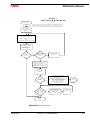
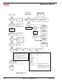
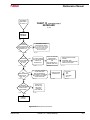
Troubleshooting
Checklist RS-232
Commmunications
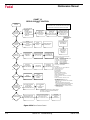
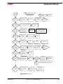
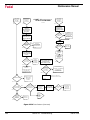
Use this procedure to determine which device or cable is not functioning
properly. At the end of each step check to see if communications are possible.
If no
communications
occur:
1. If a switch box is used, determine that the switch is in the proper position.
•
Turn the switch handle back and forth a few times. Sometimes the connections are corroded and turning the handle will TEMPORARILY correct
the problem.
2. Check to see if all cable connections are firmly connected.
•
Loose cable connections are the MOST COMMON cause of communications failures.
3. Check to see that the phone modem cable on the inside of the control cabinet is disconnected from the back of the phone modem in the modem
sleeve. Some machines do not have a phone modem in the sleeve.
•
The phone modem WILL interfere with communications through the
RS-232 port.
4. The machine must be properly grounded. Follow the grounding instructions on the green label inside the main disconnect box to confirm the
grounding connections.
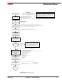
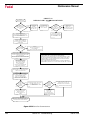
5. Check to see if the communication parameter settings in the software of the
computer are set properly.
a. Baud rate - This is variable, depending on the default setting at the
machine established in SETP or with a CD,# command
•
Sometimes a computer can communicate at the lower baud rates (600
or 1200) and not at the higher baud rates (2400 - 9600). The customer
should try a lower baud rate as a temporary solution.
b. Parity - Even
March 2003
Section 16: Troubleshooting
545
Fadal
Maintenance Manual
c. Data Bits - Seven
d. Stop Bits - One
e. EOB (End Of Byte) - CR,LF (ASCII 13,10)
f. Starting and ending character - % (ASCII 37)
g. Xon/Xoff (Software handshaking) - disabled for TA or PU, enabled
for DNC
h. Hardware handshaking - disabled
i.
The IO port number (RS-232 or serial port) on the computer must
be identified (i.e.,COM 1, COM2. COM3 or COM4).
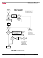
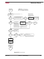
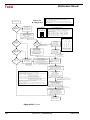
6. Determine that the IO port on the machine is functioning properly. Exercise
the port by putting a mirror plug in the port and sending a character out.
which should then be received back again.
•
The mirror plug, found in the control cabinet of the machine, is a DB-25
plug with pins 2 and 3 crossed, and is usually shipped with the
machine. or can be ordered from our parts department.
a. Put the mirror plug in the RS-232 port of the machine.
b. Move to the cold start position and go into the diagnostics mode.
c. From the command mode type DI then press the enter button.
Then type GO 3000 (G zero, space, three thousand) then press the
enter button. A menu will appear, then select number four by
pressing the 4 button. A second selection will appear. Select the
baud rate that is desired for the test by pressing one of the numbers.
d. Numbers next to the word TESTING should be changing constantly.
e. The numbers at the end of the other sentences should all be zero.
If any numbers appear at the end of these sentences an error on
the 10 port has occurred and indicates a problem with the port.
•
If this test fails the S100 board is bad or the cable on the inside of the
control cabinet is faulty or it is not plugged in properly. Change the
S100 board and cable if needed. Note: It is our experience that the
S100 board and inside cable rarely need to be changed.
f. This test can be repeated with each section of cable plugged into
the machine leading up to the computer. This will test the integrity
546
Section 16: Troubleshooting
March 2003
Fadal
Maintenance Manual
of each section. A gender changer may be needed to plug in the
mirror plug in some sections.
•
If a switch box is used in the chain of cables, it must be checked also.
Check it in the same manner that the cables were checked.
7) After thoroughly checking the machine and the cables it can be safely
concluded that something in the computer is at fault.
•
Introducing another computer into the line of communication is a quick
way to determine if the computer in question is faulty.
a. A mouse or network board. screen savers, and other software running concurrently in the host computer, may interfere with communications. Check the IRQ and DMA settings in the computer for
conflicts with the values assigned to the IO port.
b. The output voltage of the IO board across pins 7 and 12; when
transmitting a program, should be between 10 and 12 VAC.
c. The file being sent may have something wrong with it. Incorrect
syntax in a line of code may interrupt transmission.
March 2003
Section 16: Troubleshooting
547
Fadal
Troubleshooting Charts
548
Maintenance Manual
Chart 1
Chart 2
Chart 3
Chart 4
Chart 5
Chart 6
Chart 7
Chart 8
Chart 9
Chart 10
Chart 11
Chart 12
Chart 13
Chart 14
Chart 15
Chart 16
Chart 17
Chart 18
Chart 19
Chart 20
Chart 21
Chart 22
Chart 23
Chart 24
Quick Checkout
Automatic Tool Changer
Spindle Driver
Axis Control
Repeatability
Computer
Axis Motor Runaways
Baldor SWEO Spindle Drive
Z200/Z300 Spindle Drive
Keyboard
Finish Problems
Bad Power / Bad Voltage
Rotary Heads A Axis
FADAL TR65 Rotary Heads A & B Axis
Tsudakoma 301 Rotary Heads A & B Axis
Servo Coolant Control
Circle Roundness
Error Codes Reported by Axis Card
Serial Port Communications
FADAL Servo Indexer
Positioning Problems
Scale Problems
Rigid Tap
M-Function
Section 16: Troubleshooting
March 2003
Fadal
Maintenance Manual
CHART 1
Q U IC K C H E C K O U T P R O C E D U R E
DA S H ED S YM B O L S
AP PL Y TO C E N OR M
EU R O P EA N M AC H IN E S
ONLY
9- 2 0 -9 5
Q U IC K C H EC K OU T
DIF FIC UL T T O D IA GN O S E P RO B LE M S C A N O C CU R IF M AC H INE IS N O T P R OP E RL Y G R O UN D ED .
TH ER E MU S T B E A CO N TIN U O US G RO U N DIN G CO N D UC TO R (AS S PE CIF IED O N T H E G R OU N D IN G LA B EL
IN TH E M AC H INE 'S D IS CO N N EC T B O X) F RO M TH E VM C 'S GR O U ND BU S TO TH E GR O U ND B US IN T HE
BU ILD ING 'S P OW E R DIS TR IB UT IO N P AN E L.
IS TH ER E
NO
AIR PR E SS U R E?
(8 0 P SI ))
YE S
1. 1
PR OP ER AIR PR E SS U R E AN D A D EQ U ATE A IR V O L U M E IS C RI TIC A L FO R TO O L C HA N G E S.
AIR PR E SS U R E RE G U L A TOR O N MA C H IN E M US T BE S ET AS L A BE L ED (8 0 - 9 0 PS I A N D
12 0 PS I F OR TOO L O U T R EG U L A TO R ) . AIR SU P PL Y TO MA C H IN E S HO U L D BE 1 2 0 P SI .
AIR HO SE TO M AC H IN E M US T BE 3 /8 " AN D A S S HO R T A S PO S S IBL E .
AIR DI ST RI BU T IO N P IP E IN B UI L D IN G S H O U L D B E A M IN IM U M OF 3/ 4 ".
TH E PR E SS U R E DR O P A T TH E MA C H IN E D UR I N G A TOO L C H AN G E S H O U L D B E A
MA XI MU M O F 3 -5 P S I.
CO R R EC T AIR
PR E SS U R E
1. 1 .1
SE T M ET ER F O R
VA C AN D CH E C K FO R
AC R IP P L E O N
+5 V , + 1 2 V A N D - 1 2 V D C
CH E C K + 5 V, +1 2 V , -1 2 V ,
AN D 1 1 0 V AC
AT PO W ER S U P PL Y ( 12 2 0 )
(U S E O SC IL L O SC O P E
IF A VA IL A BL E )
(0 .01 5V AC R IP P LE M AX O N + /-12 V,
0.00 5V AC R IP P LE M AX O N + 5V )
1. 2
1. 3
1. 5
YE S
YE S
YE S
RE P EA TA BI LI TY
PR O B L EM ?
1. 6
1. 7
YE S
1. 7 .1
NO
KE YB O A R D
PR O B L EM ?
1. 8
YE S
1. 3 .5
CH E C K FU S ES
F5 , F6 , F7 , F8 , F 19 , F2 0
AN D C IR C U IT B RE A KE R S
CB 1 & C B 2
O N 1 1 0 0 -2
1. 4 .2
1. 4 .3
TO O L D U L L ?
OR TO O L AR G E
A C U T?
1. 5 .2
CH E C K
CI R C UI T
BR E AK ER S
(C E
MA C H IN ES )
1. 3 .6
SE E
CH A R T
NO . 4
1. 3 .7
SE E
CH A R T
NO . 2
1. 4 .4
SE E
CH A R T
NO . 3
1. 5 .3
CH E C K
TO OL I S
TIG H T
CH E C K FO R
FIX TU R E
MO V E ME N T
1. 6 .2
CH E C K
PU L S E L E D 's
ON A LL BO AR D S .
AR E TH E Y B L IN K IN G .
CH E C K
MO T O R
O VE R L OA D
RE L A YS
1. 3 .4
CH E C K TH AT R E LA Y S
K5 , K6 , K3 3 , K1 1 ,
K1 2 , K 1 3 , & K 1 4
AR E FIR M L Y SE AT ED
O N 1 1 0 0 -2 B O A R D
VE R IFY
PU L S E L E D 's
O N A LL
AX IS BO AR D S
AR E BL I N KIN G
CH E C K FO R
CH I PS IN
SP IN D L E
CH E C K D OO R S .
(C E MA C H IN E S
L IM IT M O V EM E NT
W H EN D O O R S
AR E O P EN .)
MA KE S U R E
FEE D R A TE
IS N O T
AT 0 %
1. 3 .3
CH E C K
CO L D ST AR T
PO S ITI O N
OF Z AX IS
1. 6 .1
NO
CO N TR O L
PR O B L EM ?
CH E C K
EM ER G E N C Y
STO P
BU TT O N
1. 3 .2 .
1. 5 .1
NO
1. 2 .3
YE S
1. 4 .1
NO
IS IT
A S P IN D L E
PR O B L EM ?
VE R IFY
PU L S E L E D 's
O N A LL
AX IS BO AR D S
AR E BL I N KIN G
1. 3 .1
NO
IS IT
A T OOL
CH A N G E R
PR O B L EM ?
1. 4
YE S
SE E
CH A R T
NO . 1 2
1. 2 .2
1. 2 .1
IS IT A N A XI S
PR O B L EM ?
NO
IS
PO W ER O K?
1. 6 .3
CH E C K
LE V EL N E SS
OF
MA C H IN E
AD J U ST
PO S ITI ON L O O P
G AI N AN D
FEE D R AT E C L O C K
1. 6 .4
1. 6 .5
SE E
CH A R T
NO . 5
1. 6 .7
SE E
CH A R T
NO . 6
1. 7 .2
SE E
CH A R T
NO . 1 0
1. 8 .1
GO T O
PA G E 2 O F
CH A R T 1
Figure 16-1 Quick Checkout Procedure
March 2003
Section 16: Troubleshooting
549
Fadal
Maintenance Manual
CO N T IN U E D
FROM
CH A R T 1
PA G E 1
C H A R T 1 c o ntin u e d (p a ge 2 )
Q U IC K C H E C K O U T P R O C E D U R E
9- 2 0 -9 5
IS IT
A F IN IS H
PROBLEM ?
1A .1
YES
1A .1 .1
NO
IS IT
A RO TAR Y HE AD
PROBLEM ?
1A .2
YES
YE S
IS IT A
SE R VO C OO LA N T
PROBLEM ?
1A .4
YES
MAKE SURE
P O S IT I O N O V E R R I D E
P O T IS
CE N TE R ED
V E R IF Y
SE R VO C OO LA N T
A X IS IS S E T T O
C O O L A N T IN S E T P
1A .3 .2
CH E C K SIN/C O S
S IG N A L S U S I N G
S E R V IC E T O O L S T 4 8 .
A D J U S T IF V A R IA N C E
> 0 . 00 1 V
CHE C K
BA LAN CE O F
A X IS A M P L IF IE R S
1A .4 .1
NO
ERROR
CO D E?
1A .1 .3
SEE
CHA RT
13, 14 . 0 R 1 5
1A .3 .1
NO
IS IT A
RO U N DN E S S
PROBLEM ?
1A .1 .2
SEE
CHA RT
NO . 11
1A .2 .1
NO
1A .3
CHE C K SIN/C OS
S IG N A L S U S I N G
S E R VIC E T O O L S T 4 8 .
A D J U S T IF V A R IA N C E
> 0.001 V
CHE CK
BA LAN CE O F
A X IS A M P L IF IE R S
YES
1A .5
1A .4 .2
SEE
CHA RT
NO . 16
1A .3 .3
SEE
CHA RT
NO . 17
1A .4 .3
SEE
CHA RT
NO . 18
1A .5 .1
NO
IS IT A
C O M M U N IC A T IO N
PROBLEM ?
YES
1A .6
V E R IF Y
BAUD RATE AND
C O M M U N IC A T IO N
PA RAM ET ER S
V E R IF Y
CO N N EC TIO N
OF R S 232 C AB LES
1A .6 .2
1A. 6.1
SEE
CHA RT
NO . 19
1A .6 .3
NO
IS IT A N
IN D E X E R
PROBLEM ?
YES
1A .7
YES
1A .7 .1
NO
IS IT
A N M -F U N C T IO N
PROBLEM ?
1A .8
IS IT A
FAD A L
IN D EX E R ?
SEE
CHA RT
NO . 20
1A .7 .2
NO
YE S
NO
SEE
CHA RT
NO . 24
1A .8 .1
GO TO
PAGE 3 OF
CH A R T 1
Figure 16-2 Quick Checkout Procedure (Continued)
550
Section 16: Troubleshooting
March 2003
Fadal
Maintenance Manual
CHART 1 continued (page 3)
QUICK CHECKOUT PROCEDURE
CONTINUED
FROM
CHART 1
PAGE 2
IS IT A
POSITIONING
PROBLEM?
1B.1
9-20-95
YES
NO
DOES
MACHINE HAVE
SCALES?
1B.1.1
NO
SEE
CHART
NO. 21
1B.1.2
YES,
START WITH SCALE CHART
IS IT A
SCALE
PROBLEM?
YES
1B.2
1B.3
SEE
CHART
NO. 22
1B.2.1
NO
IS IT A
RIGID TAPPING
PROBLEM?
REMOVE COVER
FROM SCALE
BOX ON OUTSIDE
OF CONTROL BOX
AND CHECK FOR
ERROR LED
YES
1B.2.2
SPINDLE INVERTER
MUST BE LABELED
"RIGID TAPPING"
SPINDLE SOFTWARE
(IN 1010-S)
MUST BE
RIGID TAP
1B.3.1
NO
1B.3.2
FOUNDATION IS IMPORTANT
IS IT A
VIBRATION
PROBLEM?
1B.4
YES
SEE
CHART
NO. 23
1B.3.3
SEE MAINTENANCE MANUAL
FOR DETAILS
MOVE ONE AXIS
AT A TIME TO
DETERMINE WHICH
AXIS HAS VIBRATION
PROBLEM
CHECK ALIGNMENT OF
MOTOR MOUNTS
AND
BALLSCREW MOUNTS
1B.4.1
1B.4.2
1B.4.3
MACHINE MUST BE POSITIONED ON
A SINGLE SLAB OF CONCRETE
WITHOUT CRACKS
CONSULT
CHART 3,
CHART 22,
CHART 23
1B.4.4
Figure 16-3 Quick Checkout Procedure (Continued)
March 2003
Section 16: Troubleshooting
551
Fadal
Maintenance Manual
CH AR T 2
A UT OM A T IC T OO L CH AN G E R
TOOL CH A N GE R
10-18-95
PROP ER AIR PR E SS U RE AN D A D EQ UATE A IR V OLU M E IS C RI TIC A L FOR TOOL CHA N GE S.
AIR PR E SS U RE RE GU LA TOR O N MA C H IN E M US T BE S ET AS LA BE LED (80-90 PS I A N D
120 PS I F OR TOO L OU T R EGU LA TOR ). AIR SUP PLY TO MA CH IN E S HO ULD BE 120 P SI .
AIR HO SE TO M AC H IN E M US T BE 3/8" AN D A S S HO R T A S POS S IBLE .
AIR DI ST RI BU T ION P IP E IN B UI LD IN G S HOULD B E A M IN IM U M OF 3/ 4".
TH E PR E SS U RE DR O P A T THE MA C HIN E DURI N G A TOO L C H ANG E S H OU LD B E A
MA XI MU M OF 3-5 P S I.
US E T OOL IN/ OU T
TO IN S ER T /R E MO VE
TOOL F RO M S PI N D LE
2. 1
DO ES
TOOL I N/OUT
W OR K ?
2. 2
CH E C K AI R PR E SS U R E
(80P SI AN D 120P SI )
(M AX 3-5 PS I DR O P
DU R I NG TOO L
CH A N GE )
NO
2. 2.1
YE S
PRE SS
TUR R ET CW
AN D
TUR R ET C C W
MA N U ALLY AC T IVA TE
DR A W B AR SOLE N OID
AT MA C A IR
VA LVE A SS Y.
CH E C K
F20 AN D K24
ON 1100-2.
2. 2.2
2. 2.3
(IF A T OOL IS IN
TH E S PIN D LE ,
HA VE H EL PE R
HO LD O N TO IT.)
EUROP EAN CE N ORM
MACH INES M UST HAVE
DOOR S CLOSED FOR
ATC TO WORK PROPER LY
DO ES
DR A WB AR W OR K
W H EN M A NUA LLY
OPE R AT ED ?
2. 2.4
NO
CH E C K AI R
DE LIV ERY TO
DRA WB AR
CY LIN D E R .
2. 2.6
YE S
CHE CK 1040 AN D W IR ING
(S EE D R A WIN G 1002
AN D K EY B OAR D
TR OU BLE S HO OTI NG
DI AG RA M )
CH E C K D RAW B A R
CY LIND E R FOR
BA D SE A LS O R
BR OK EN PI STO N
2. 2.7
2. 2.5
2. 3
DI D
TU R RET MOV E
C ORR E C TLY?
2. 4
EM ER GE NC Y ST OP
MUS T B E RE LE AS ED
AN D
AM PLIF IE RS R E SE T
NO
2. 4.1
C2 ON 1100-2 MU S T
BE B YP AS S ED .
2. 4.3
GEN E VA
2. 5
2. 4.2b
2. 4.2a
DI D
SP IN DLE
OR IE NT ?
CH E C K TUR R ET
FA CTOR I N SE TP .
CH E C K GE NE V A
M EC H A N ISM .
CH E C K TUR R E T
M OTOR WIR IN G.
CH E C K FU SE S F5 & F6 & CB 2
AN D RE LAY S K5, K33,
K11, & K 12 ON 1100-2.
K12 M U ST BE R A TE D FOR
3 AM P OU TP U T (BLA C K) .
IN M DI E N TE R M19
NO
DI D
SP IN D LE
TU RN ?
2. 6.1
YE S
YE S
DI D
OR IE NT AT ION
AR M SW IN G
IN ?
2. 6.2
GO T O
CHA RT
NO . 3
SP IN D LE
DRI VE R
NO
ADJ UST
OR IE NT AT ION
FAC T OR
IN S ETP
2. 6.2a
NO
2. 4.4
C H ECK S ER V O T U RRE T ME C HAN IS M
FOR B IN D ING OR E XC E SS IV E PLA Y.
CH E C K TU R R ET MO TOR W IR IN G.
CH E C K TU R RET MO TOR E N C OD E R
AND W I R IN G.
2. 4.5
IF T UR R E T A M PLIF IER FUSE I S
BLOW N OR O VE R-C UR R E N T
LE D IS O N, C H ECK M OTO R
WIR E S F OR S H OR T T O C H AS S IS.
(WI R ES TO MO TOR
AR E SH I ELD E D ;
SH IE LD M US T BE S TR IP PE D
BA C K F ROM C ON D UC TOR).
2. 6.1a
YE S
CH E C K FU SE S F5 & F6 & CB 2
AN D R E LAY S K5, K33,
K11, & K 12 ON 1100-2.
K12 M UST BE LOW
LE A KA GE (GREE N ).
CH E C K F4 A N D
SE R VO TUR R ET FUS ES .
TU R RET FAC T OR
IN S ETP M U ST BE 1
FOR S E R VO TU RR ET .
SE R VO
2. 4.2
YE S
GO TO C S PO SI TI ON.
(I F N O T C O LD S TA R T ED ,
DO A C OLD ST A RT.)
2. 6
GE NE V A
OR S E RVO
TU RR ET ?
GO T O
CH A R T
NO . 3
SP IN D LE
DR I VE R
2. 4.6
IF T UR RE T M OV ES
CO R REC TLY E XC E PT
FOR D IR E C TIO N,
CHA NGE D IR E C TION
CO N TR OL FR O M
TB1- 7 TO TB 1-5
ON 1100-2
(OR VICE V ER S A)
2. 6.2b
CH E C K
F19 & K23
ON 1100-2
2. 4.7
2. 6.3
IF TU R RE T R U NS A WAY :
1 .RE V ER SE MO TOR LE AD S ,
2 .CH E CK EN C O DE R WIRIN G,
3 .RE P LA CE EN C ODE R ,
4 .RE P LA CE TU R RE T
C ONT RO L MOD U LE .
RE M OV E TO OL
FR OM S PI N D LE
AND MAN U A L LY A CTI VA T E
OR IE N TA TI ON A IR S OL EN O ID
AT M A C AI R V A LV E ASS Y .
2. 4.8
2. 6.4
DI D
OR IE NT AT ION
ARM SW IN G
IN?
2. 6.5
GO T O
PA GE 2 OF
CH A R T 2
2. 7
YE S
NO
CH E C K AI R PR E SS U R E.
CH E C K AN D RE P AIR
OR IE NT M EC H A N ISM
AN D A IR LIN E S .
IF V ERY HE AV Y TOO LS
AR E U N EV E NLY
DI ST RI BU TE D,
RE D IS TR IB UTE TOO LS
ON TUR R E T
CHE CK WIR I NG.
TR Y KN OW N
GOOD 1040.
2. 6.6
2. 4.9
D IP S W ITC H SE TT ING S
SP EE D
SW 1
S W2
F AS T
OP E N
OP E N
M E DF A ST C LO S E D O PE N
M E DS LO W O P EN
C L OS E D
S LO W
C LO S E D C LO S ED
MO T OR T YP E: S W3 & SW 4 O PE N
C O N SU LT FA CT ORY A BO U T O TH E R
MO T OR S ET TIN GS.
CO N SU LT FACT OR Y
SE RVIC E D E PT .
AB OU T D I P S WI TC H
SE TTIN G S F OR
SP EE D A N D PI D
2. 4.10
2. 6.5a
Figure 16-4 Automatic Tool Changer
552
Section 16: Troubleshooting
March 2003
Fadal
Maintenance Manual
C H A R T 2 c o nti nu e d (p a ge 2 )
A U T OM A T IC T OO L C H A N G E R
CO N TIN U E D
FR OM
PA GE 1 OF
CH A R T 2
1 0 -1 8 - 9 5
MA N U A LL Y MO VE A T C
TO EX TE N D E D P OS ITI ON
(G R AS P A N D SW IN G
UP P ER GE N E VA A R M)
2A .1
NO
DI D
ME C H AN IS M MO VE
SM OOTH L Y ?
2A .2
2A .2 .2
2A .2 .1
YE S
IS
TOOL C A R R IE R
PR OP ER L Y A L IGN E D
W ITH S P IN D L E?
RE P L AC E
ME C H AN IS M
IF D A MA GE D
CL E A N, A DJ U S T,
AN D L U B R IC AT E
ME C H AN IS M
NO
CH E C K AN D A D J US T
TU R R ET FAC T OR
CH E C K IF T OOL
CA R R IE R IS OU T
OF P OS ITIO N
OR S KE W E D
DU E TO A C R AS H
(T U RR E T FA C TO R
MU S T B E 1 FO R
SE RV O TU R RE T.)
2A .3
2A .3 .1
2A .3 .2
AD J U ST
TU R R ET AL IG N ME N T
AN D /O R
CO L D ST AR T PO SIT ION
2A .3 .3
(S E RV O TU R RE T M U S T
MA K E A M OV E BE FO R E
TU RR E T A LIG N ME N T IS
AD JU ST E D.)
YE S
RE TU R N A TC T O
RE TR A C T ED PO SI TI ON .
TH EN IN MD I E N TE R
M6 T2
(IF TO O L 2 IS IN T H E
SP IND LE , U SE M 6T 1.)
2A .4
DI D
ATC SL ID E
CO ME
IN ?
NO
2A .5
YE S
AR E
FU SE S
F7 , F8 , & C B1
AN D R E L AY S K6 ,
K1 3 & K 1 4
OKA Y ?
2A .5 .1
YE S
CH E C K AT C H OME S W IT C H .
CH E C K A TC FA U L T S W IT CH .
CH E C K C ON TR OL
V OL TA GE A T K 1 4 .
CH E C K SL I DE M OTO R
& W I R IN G.
CH E C K AT C
AL IG NM E N T
2A .5 .2
NO
2A .5 .3
CH E C K SL I DE M OTO R
BE L T TE N SI ON
AN D A D JU S TM EN T
O F G EN E VA S L OT
2A .5 .4
RE S ET C B1 O R
RE P L AC E
F7 , F8 , K 6, K 13 , K 14
AS N EE D E D
2A .5 .1 a
DI D
YE S
TOOL C A R R IE R
CR A S H IN TO
SP IN D L E?
2A .6
TU R R ET MU S T B E
AT AN E M PTY
POC K ET
(A D JU S T S ET TO)
2A .6 .1
NO
AD J U ST
CO L D ST AR T PO SIT ION ,
AN D TU R R E T A L IGN M EN T
2A .6 .2
(S E RV O TU R RE T M U S T
MA K E A M OV E BE FO R E
TU RR E T A LIG N ME N T IS
AD JU ST E D.)
CH E C K TU R R ET FA C TOR
FOR GE N E VA .
CH E C K EN C OD E R A N D
EN C OD E R W IR I NG
FOR S E R VO TU R R ET .
2A .6 .3 (T U RR E T FA C TO R M US T
BE 1 FO R SE R VO T UR R ET .)
GO T O
PA GE 3 OF
CH A R T 2
2A .7
Figure 16-5 Automatic Tool Changer (Continued)
March 2003
Section 16: Troubleshooting
553
Fadal
Maintenance Manual
C H A R T 2 continu ed (page 3)
AUTOM A TIC TOO L CHA NG E R
10 - 1 8 -9 5
C O N T IN U E D
FROM
PA GE 2 OF
CH A R T 2
P R O P E R A IR P R E S S U R E A N D A D E Q U A T E A IR V O L U M E IS C R I T IC A L F O R T O O L C H A N G E S .
A IR P R E S S U R E R E G U L A T O R O N M A C H IN E M U S T B E S E T A S L A B E L E D (8 0 - 9 0 P S I A N D
12 0 P S I F O R T O O L O U T R E G U L A T O R ) . A IR S U P P L Y T O M A C H IN E S H O U L D B E 1 2 0 P S I .
A IR H O S E T O M A C H IN E M U S T B E 3 /8 " A N D A S S H O R T A S P O S S IB L E .
A IR D I S T R I B U T IO N P IP E IN B U I L D IN G S H O U L D B E A M IN IM U M O F 3/ 4 " .
T H E P R E S S U R E D R O P A T T H E M A C H IN E D U R I N G A T O O L C H A N G E S H O U L D B E A
M A X I M U M O F 3 -5 P S I.
DI D
Z A X IS
GO UP?
IS
TOOL STUCK
IN S P IN D L E ?
NO
2B .1
IS
DR A W B A R
FU SE OK A Y?
(F 2 0 )
YE S
2B .1 .1
2B .1 .2
CH E C K
CH E C K
CH E C K
CH E C K
S L I D E E X T E N D E D S W IT C H .
A T C F A U LT S W IT C H .
D R A W B A R S W IT C H .
Z A XIS SE R VO.
NO
CH E C K
DR A W B AR SW I TC H
(A N D A D J U S T M E N T ) ,
AN D D R A W BA R
C Y L IN D E R A S S Y
RE P LAC E
FU SE
F20
2B .1 .1 a
YE S
A IR P R E S S U R E M U S T B E
80 P S I A N D 1 2 0 P S I
(M A X 3 - 5 P S I D R O P
DU R I NG TO O L C H AN G E)
2B .1 .3
NO
NO
YE S
IS
M A C H IN E IN
A T A P -T A P
CY C L E?
YE S
2B .1 .2 a
2B .1 .4
CH E C K K24
AN D C O N T RO L
VOLT AGE TO K 24
2B .1 .5
2B .1 .3 a
DI D
TURRET
IN D E X ?
2B .2
NO
YES
DI D
TURRET
STO P?
GO B AC K
TO S TA RT OF
CH A R T 2
2B .1 .6
2B .2 .1
NO
IF O V E R S H O O T /
UN D E R SH O OT
CH E C K/ AD J U ST
TU R R ET FAC T OR
CH E C K TU R R ET
F E E D B A C K S W IT C H
2B .3
2B .3 .1
YE S
DI D
Z A X IS C O M E
DO W N ?
NO
YES
YE S
NO
CH E C K AT C
A L IG N M E N T &
BE LT TE N SION
2B .5 .1 a
DI D
S L ID E M O T O R
STO P?
2B .6
NO
D I D S P IN D L E
DR O P T OO L ?
2B .7
NO
CH E C K AT C
S L ID E H O M E
SW ITC H
2B .6 .1
YE S
YE S
CH E C K
CO L D ST AR T
P O S IT I O N .
2B .7 .1
(T U R R E T F A C T O R
MU S T B E 1 FO R
SE RV O TU R RE T.)
2B .3 .3
2B .4 .2
DI D
Z A X IS G O
UP ?
2B .5 .1
GO BACK
TO S TA RT OF
CH A R T 2
CH E C K AT C
SA FE TY SW ITCH
2B .4 .1
YE S
2B .5
2B .3 .2
CH E C K
Z A X IS
SE R VO
NO
2B .4
DI D SL I D E
PU LL B AC K ?
TO O L H O L DE R S
MU S T B E CLE A N .
CH E C K D R AW BA R
VA LVE FU S E F20 .
CH E C K Z A XI S
FOLLOW ING
ER R OR ,
IS IT E X C E S S I V E ?
C H E C K K 2 4 A N D IT S
CO N TR O L V OL TA G E .
2B .5 .2
CH E C K FU SE S
F7 & F8 & CB1.
CH E C K R EL A YS
K6, K13, & K 14
2B .5 .1 b
2B .5 .3
CH E C K:
S L I D E E X T E N D E D S W IT C H ,
A T C F A U LT S W IT C H ,
D R A W B A R S W IT C H ,
SL I DE M O TO R
2B .5 .1 c
CH E C K AIR PR E SS U R E
(8 0 P S I ) A N D 1 2 0 P S I
(N O T T O E X C E E D
3- 5 P S I D R O P D U R IN G
TOOL CHA NGE )
2B .5 .4
SE E
TOOL CHA NGE R
AD J U STM E NT S
IN M A IN T E N A N C E
MA N U AL
2B .5 .5
CH E C K
AD J U STM E NT O F
GEN E VA S LOT
2B .6 .2
MAKE SURE T OOL
HA S PR O PE R
PULL STUD.
2B .7 .2
ATC SY ST EM S OK
END
2B .8
Figure 16-6 Automatic Tool Changer (Continued)
554
Section 16: Troubleshooting
March 2003
Fadal
Maintenance Manual
DA SHED SYM BOLS
APPLY TO CE NORM
EUROPEAN M ACHINES
ONLY
CHART 3
SPIND LE DRIVE R
SPINDLE DRI VER
10-20-95
DIF FICUL T T O D IA GN OS E P ROB LE MS CA N OCCU R IF MAC HINE IS NOT P R OP E RL Y GROUN DED .
TH ERE MU ST B E A CONTINUOUS GROUNDIN G CON DUCTOR (AS S PE CIF IED ON T H E GROUND ING LA B EL
IN THE MACHINE 'S D IS CON NECT B OX) F ROM THE VMC'S GR OU ND BUS TO THE GROUND B US IN T HE
BUILDING'S P OWE R DIS TR IB UT ION P AN E L.
NOT E:
SPINDLE WILL NOT
RUN ON A CE M ACHINE
WITH THE DO ORS OPEN
CHE CK ERROR MESS AGES
ON INV ERTE R DISPLAY
(M ITSUBI SHI INVE RTERS
REQUIRE INSTA LLAT ION
OF PARAM ETER UNIT )
CO RRECT FAULT
AND RESET I NVERTER
3. 1
NO
DO ES
SP INDLE
RUN?
3. 2
WILL
SP INDLE TURN
BY HAND?
3. 2.1
NO
3. 2.2
YES
YES
IS
SP INDLE POT
AT 0?
3. 2.1a
SP INDLE
MA Y BE
FROZE N
CHECK
BELTS
3. 2.3
CHA NGE
SPINDLE
POT
SETTING
YES
NO
3. 2.1a.1
VERIFY LE D ON
SPINDLE 1010
(S LOT 14)
IS BLINKING
CHECK
AND RESET
OVERLOA D
RELA Y
3. 2.1b
3. 2.1b.1
CHECK
AIR
PRE SS URE
(80-90 PS I)
3. 2.1b.2
CHECK
AND RE SE T
CE CIRCUIT
BREAKERS
A12, B12, C12
CHECK
3-PHASE AC
POW ER T O
INVERTER
3. 2.1b.3
3. 2.1b.4
CHECK ERROR MESSAGES
ON INVERTER DISP LAY
(M ITS UBI SHI INVERTE RS
RE QUIRE INS TALLAT ION
OF P ARAM ETER UNIT )
AFT ER F AULT IS CORRECTE D
PRESS RESET O N INVERTER
3. 2.1b.5
RUNS
3 SECONDS
AND STOPS?
(ERROR #8)
YE S
NO
3. 3
CHECK SPINDLE
HALL EFFECT SWIT CH
AND WI RING
(USE DI DS TO S EE I F
SWI TCH IS B EI NG READ)
ON 1100-2:
CHECK F1 & F3.
CHE CK K7, K9,
K3, & K4.
3. 3.1
3. 2.1b.6
MOT OR
TURNS B UT
SP INDLE DO ES
NO T OR
SLIP S?
3. 4
YES
YES
NO
3. 5
YE S
SPINDLE
TAKES A LONG
TIM E T O
STO P?
NO
3. 6
SP INDLE
SP EE D
VARIES ?
3. 7
NO
CO NTINUED
ON PAGE 2
SPINDLE DRI VER
(CHA RT 3)
3. 8
DO NOT OVE R TIGHTE N
BE LT S
3. 4.1
NO
SP INDLE
RUNS IN ONE
DI RECTI ON
ONLY?
INSPECT BELTS
AND BELT TENSIO N
CHECK
AIR PRE SS URE
(SHOULD BE
80-90 P SI )
CHECK
F3, K 9, & K4
ON 1100-2
3. 5.1
3. 5.2
CHECK REGEN
RESIST OR OR
EXTE RNAL BRAK E
3. 6.1
YES
CHECK/ ADJ UST
J1 CONNECTOR *
ON SPINDLE CARD
3. 7.1
3. 4.3
3. 4.2
CHECK FOR
LO OS E W IRES
OR TERMI NALS
*
3. 6.2
VE RIFY THA T
1010S /J 1, J2, & J 3 *
AND 1100-1/ J2 & J3
ARE PLUG GED IN
3. 2.1b.7
*GOL D COAX C ONNE CT OR
M US T FIR MLY GRIP CE N TE R P IN (US E
S ERV ICE TOOL S T4 4 T O T ES T A N D A DJUST ),
M US T B E S OLIDLY CRIM PE D T O CEN TE R WIRE ,
M US T MAK E FIRM C ONTA CT WITH JA CK.
US E OHM METER
TO CHECK
REGEN RESISTO R
(CHE CK DRA WING
1002 FOR VALUE)
IF SPI NDLE STILL
DO ES NOT RUN,
CHECK FUSES IN I NVERTE R,
THEN T ES T I NVE RTER
USING BATTERY BO X
(SERV ICE TOO L ST 03)
3. 2.1b.8
SPINDLE
RUNS WI TH
BATTERY
BOX ?
CHECK FUSES
IN INVERTE R
YES
SP INDLE CARD
MAY BE BAD.
SWAP IN KNOWN
GOOD 1010-S
3. 2.1b.9
NO
3. 2.1b.10
3. 6.3
CHECK MO TOR WI TH
OHMM ET ER
LE G TO LEG
ABOUT 0. 6 OHM .
LEG TO G ND O.L.
3. 7.2
INSPECT
HI /LOW RANGE
MECHANIS M
CHECK
SP INDLE
ENCODER
WITH ENCODE R
TESTER
CHECK FOR VOLTAGE
AT OVERLOAD RELAY
TO DE CIDE IF M OT OR
OR INV ERTER I S BAD
3. 2.1b.11
3. 7.3
TY PICAL SYM PTOMS O F A
CO NSULT FACT ORY
BAD ENC ODER :
SERVICE DEPT .
BALDOR SWEO :
BE FORE REP LACING
SPINS SLOWLY, SIN KS LOTS OF CU RREN T,
MOT OR OR
THEN FAULTS O UT (OC ).
MITSUBIS HI:
INVERTER
NO VISIB LE S YMPTOM S
MITSUBIS HI DOE S NOT RE QUIRE ENCO DER
3. 2.1b.12
FEEDBACK TO RUN .
PERFOR MANC E SUFFERS ( BUT NO T OBVIOU SLY).
Figure 16-7 Spindle Driver
March 2003
Section 16: Troubleshooting
555
Fadal
Maintenance Manual
CHART 3 continued (page 2)
SPINDLE DRIVER
CONTINUED
FROM PAGE 1
SPINDLE DRIVER
(CHART 3)
SPINDLE
IDLERS WILL NOT
SWITCH?
3A.1
10-20-95
YES
USE DI DS TO CHECK
HALL SWITCHES
CHECK 0-5V SWITCHING
AT K27 AND K10 ON 1100-1
(IDLER WILL NOT SWITCH
UNLESS OTHER IDLER IS IN
01=OUT 00=IN)
(5V PULL-UP IS SUPPLIED
THRU THE RELAY,
SO RELAY MUST BE IN PLACE)
3A.1.1
NO
ORIENTATION
FAILURE?
CHECK SPINDLE
TYPE IN SETP
(CPU WILL NOT SWITCH
IDLERS IF IT IS NOT A
HI/LOW SPINDLE TYPE)
YES
3A.2
BUZZ WIRING
FROM
1060 J10-8
TO
SLOT 14 J2
USE DI DS
TO CHECK
ORIENTATION
MAGNET
3A.2.1
3A.3
YES
YES
3A.2.4
USE ENCODER TESTER
TO TEST AT EACH
CONNECTOR FROM
ENCODER TO INVERTER
3A.3.2
REMOVE BELTS,
RUN SPINDLE AT
MAXIMUM SPEED
AND CUT POWER
(MOTOR COASTS
TO STOP)
DOES
SPINDLE MOTOR
SHAKE WHILE
COASTING?
YES
DOES
VIBRATION
OCCUR WHILE
COASTING?
3A.5.2
CONSULT FACTORY
SERVICE DEPT.
BEFORE REPLACING
SPINDLE MOTOR
CONSULT FACTORY
SERVICE DEPT.
ABOUT BALANCING
SPINDLE MOTOR
3A.4.3
NO
BRING SPINDLE TO
MAXIMUM RPM AND
SHUT OFF POWER
3A.5.1
YES
3A.4.2
3A.4.1
NO
3A.5
CHECK THAT
TERMINALS ON
GREEN CONNECTOR
ON INVERTER ARE TIGHT
AND CLAMPED ON WIRE
(NOT INSULATION)
3A.3.1
3A.4
SPINDLE
VIBRATION?
3A.2.3
ORIENTATION MAGNET IS READ BY CPU THROUGH 1060 J10 PIN 8
BUT THE SPINDLE CARD READS IT THROUGH J2.
IF WIRING IS BAD, CPU MAY BE ABLE TO READ MAGNET,
BUT THE SPINDLE CARD MAY NOT BE ABLE TO READ IT.
NO
SPINDLE
MOTOR
SHAKES?
IF ORIENTATION
SOLENOID IS NOT
ACTIVATING
CHECK F19 AND
K23 ON 1100-2
ADJUST
ORIENTATION
FACTOR
IN SETP
3A.2.2
NO
"BAD
ENCODER" ON
BALDOR-SWEO
INVERTER?
3A.1.3
3A.1.2
3A.4.4
RUN AN EXTERNAL
CABLE BETWEEN
ENCODER ON MOTOR
AND INVERTER
NO
3A.5.3
YES
POSSIBILITIES:
BELTS,
PULLEY OUT OF ROUND,
MOTOR SHAFT BENT,
BAD SPINDLE.
NO
DOES
SHAKING/VIBRATION
STOP?
CONSULT FACTORY.
3A.5.4
3A.5.5
YES
3A.5.2a
ENCODER CABLE IS BAD,
INCORRECTLY ROUTED,
OR INCORRECTLY SHIELDED.
CONSULT FACTORY.
3A.5.4b
POSSIBILITIES:
INVERTER SOFTWARE,
BENT ENCODER PIN,
ENCODER DISK RUNOUT,
BAD ENCODER,
CONSULT FACTORY
SERVICE DEPT.
ABOUT INSTALLING
SOLID MOTOR MOUNTS
3A.5.6
CONSULT FACTORY
SERVICE DEPT.
BEFORE REPLACING
INVERTER
3A.5.7
Figure 16-8 Spindle Driver (Continued)
556
Section 16: Troubleshooting
March 2003
Fadal
Maintenance Manual
CHART 4
A XIS C O N T R O L
AX IS C ON TR OL
DA S H ED S YM B OL S
AP PL Y TO C E N OR M
EU R OP EA N M AC H IN E S
ON L Y
10 - 2 0 -9 5
IS
AX IS AT
LI MI T?
YE S
4. 2
4. 2 .1
NO
IS IT
A RUNAWAY
PR OB LEM ?
DIF FIC UL T T O D IA GN O S E P RO B LE M S C A N O C CU R IF M AC H INE IS N O T P R OP E RL Y G R O UN D ED .
TH ER E MU S T B E A CO N TIN U O US G RO U N DIN G CO N D UC TO R (AS S PE CIF IED O N T H E G R OU N D IN G LA B EL
IN TH E M AC H INE 'S D IS CO N N EC T B O X) F RO M TH E VMC 'S GR O U ND BU S TO TH E GR O U ND B US IN T HE
BU ILD ING 'S P OW E R DIS TR IB UT IO N P AN E L.
MOV E OFF
LI MI T
POS ITI ON
W AS
MOT OR
RE P L AC E D ?
YE S
4. 1
4. 1 .1
NO
4. 1 .2
YE S
NO
AR E
AL L 3 A X ES
RU N N IN G
AW A Y ?
GO T O
CH A R T 7
CH E C K VO L TAG ES :
+5 V , + 12 V, - 12V &
1 1 0V AC A T 122 0
YE S
IF V OL TA GE S AR E
OU T OF TOL E R AN C E ,
CH A N GE L OGI C
POW ER S U PP L Y
(A L SO C HE C K F OR A C
RIP PL E O N DC V OL TA G ES :
0.01 5V AC MAX O N +/-1 2V
0.00 5V AC MAX O N +5 V)
NO
4. 1 .4
4. 1 .3
DO ES
TH E AX IS R U N
TO A LIM IT?
YE S
4. 1 .1 a
4. 1 .2 a
IS AX IS
CO MP L ET EL Y
IN OP ER A TIV E?
YE S
4. 3
4. 3.1
NO
IS TH ER E
AN A MP L IFI ER
FAU LT?
4. 4
CH E C K C E
CI R C UI T
BR E AK ER S
(A 1 0 ,B1 0, C1 0
OR 1 4 )
CH E C K
MOT OR
OVE R L OA D
RE L A Y
YE S
4. 3.2
NO
DI D
PR OB L EM
FOL LOW TH E
AM PL IF IE R
CA R D ?
SW A P
SE R VO
AM PL IF IE R
CA R D
4. 3 .4
4. 3 .3
SW A P TH E AX IS
CO N TR OL L ER
CA RD S (1010)
(R E ME MB E R TO
CH A N GE J UM P ER
BL OC K ON J 4)
NO
YE S
4. 3 .5
DI D
YE S
PR OB LEM
FOL L OW TH E
AX IS
CA R D ?
RE P LAC E
SE R VO
AM PL IF IE R
CA R D
CH E C K
EM ER GE N C Y ST OP
AN D
MOT OR OV ER L O AD
RE L A YS
4. 3 .6
4. 3 .4 a
4. 4.1
RE P LAC E
AX IS
CO N TR OL L ER
CA R D
4. 3 .7
NO
NO
CH E C K C E
CI R C UI T
BR E AK ER S
(A 1 0, B 1 0 , C 10
OR 1 4 )
W AS TH E
PR OB L EM
RU N A W A Y?
4. 3 .6 a
YE S
RE P LAC E
RE S OL VE R
4. 3 .6 a .1
NO
4. 4 .2
WAS
MOT OR
RE C E NT L Y
RE P L AC E D OR
RE W I RE D ?
4. 4.3
YE S
4. 4 .4
NO
A OR B
AX IS W H IC H A R E
NO T IN U SE ?
4. 4 .3a
YE S
YE S
NO
IF A OR B A X IS AR E
NO T U S ED T H EY
MU S T B E IN AC T IVE
IN P AR A ME TE R S O R
DU M M Y P L U G M U ST
BE IN P L A CE .
4. 4 .3 a .1
NO
IS IT
Z-A X IS?
AR E
MOT OR W I RE S
SH OR TE D TO
CH A S SIS ?
MOT OR W I RE S
AR E SH I EL D E D .
VE R IFY TH A T S H IE L D
IS STR I PP ED BA C K
FR OM C ON D U C TOR .
VE R IFY TH A T
DU M M Y P L U G
SH OR TS
PIN S H & G
W ITH P OW ER O N
AN D D U M MY P L U G
IN ST AL LE D , V ER IF Y
TH AT 11 0 0 -1 T B1
PIN 1 TO P IN 6 IS 0 V
4. 4 .3 a .2
4. 4 .3 a .3
DO ES
IT M OV E
FR EE L Y?
TR Y TO M OV E Z-A X IS BY H A N D .
4. 4 .3 b
GO T O
PA FE 2 OF
CH A R T 4
PR E SS J OG.
DO A MP L IFIE R S
STA Y ON ?
4. 4 .3c
4. 4 .3 b .1
NO
NO
CH E C K K1 , K2 ,K 18 ,K 2 0,
F1 2 , & F1 4
ON 1 1 0 0-1 .
CH E C K OV ER L OA D
RE L A YS
4. 4 .3 c. 1
4. 3 .6 b
4. 4 .5
DO N O T M OV E Z-A X IS !
PR E SS EM E R GE N CY ST OP .
YE S
CO N SU L T FAC T OR Y
SE R VIC E D E PT .
BE FOR E R EP L A C IN G
SE R VO MO TOR
4. 4 .3 b .2
W ITH P OW ER O N
AN D D U M MY P L U G
IN ST AL LE D , V ER IF Y
TH AT 1 0 6 0 J5 - 6 A N D
J4 - 6 AR E 0V
4. 4.3 a .4
NO
CO N SU L T FAC T OR Y
BE FOR E R E PLA C IN G
BA L LSC R E W
4. 4 .3 b .3
YE S
JU M PE R
EM ER GE N C Y
STO P C I R CU I T
(J U MP F1 6 T O F12
ON 1 1 00 -1 )
CH A N GE A MP
IN D IC AT ED B Y
FAU LT LIGH T
4. 4.3 c. 2
4. 4.3 c. 3
Figure 16-9 Axis Control
March 2003
Section 16: Troubleshooting
557
Fadal
Maintenance Manual
CHART 4 continued (page 2)
AXIS CONTROL
CONTINUED
FROM
PAGE 1 OF
CHART 4
MOTOR
OVERLOADS?
10-20-95
4A.1
4A.2
TEMPERATURE SNAP SWITCH
WILL SHORT COS SIGNAL TO GND
ON RESOLVER BOARD IN MOTOR
IF MOTOR OVERHEATS.
CHECK COS OUTPUT TO RESOLVER
(PIN 8 OF J1-J6 ON 1060)
FOR SHORT TO GND.
LET COOL.
CHECK AND ADJUST
RESOLVER CONNECTOR
AT AXIS CARD J2 WITH
SERVICE TOOL ST44
*
4A.2.2
4A.2.1
NO
4A.2.3
RESOLVER
FAULTS ON
MULTIPLE
AXES?
4A.2.4
RUNS
ROUGH?
YES
ALL 3
AXES RUN
ROUGH?
YES
4A.3.1
4A.3
* GOLD COAX CONNECTOR :
MUST FIRMLY GRASP CENTER PIN (USE SERVICE
TOOL ST44 TO TEST AND ADJUST),
MUST BE SOLIDLY CRIMPED TO CENTER WIRE,
MUST MAKE FIRM CONTACT WITH JACK.
4A.1.3
4A.1.2
ISOLATE
WHICH AXIS
USING 201060-0-1
RESOLVER
TESTBOARD
YES
GO TO
PAGE 3 OF
CHART 4
(SHOULD BE APPROX. 130-165VDC
DEPENDING ON MODEL)
CONSULT FACTORY IF DIFFERENT
4A.1.1
NO
RESOLVER
FAULTS?
CHECK BUS VOLTAGE
AT BLUE CAPACITOR
ON AMPLIFIER CHASSIS.
CHECK AND ADJUST
COMMAND CONNECTOR
AT AXIS CARD J1 WITH
SERVICE TOOL ST44
*
YES
NO
NO
CHECK AND ADJUST
RESOLVER CONNECTOR
AT AXIS CARD J2 WITH
SERVICE TOOL ST44
*
CHECK RESOLVER
4A.3.1a
CHECK SINE &
COSINE OUTPUT
OF CLOCK CARD
(1020) USING
SERVICE TOOL ST48
4A.3.2
CHECK
WAYLUBE
4A.3.1a.1
CHECK
RESOLVER
CABLE.
REPLACE
RESOLVER.
NO
4A.2.5
YES
CHECK
+12V & -12V
ON 1220
CHECK
J14 ON 1060
4A.2.4a
4A.2.4b
CHECK
1060-0-1 OR
JUMPER PCB
IN J14 OF 1060
4A.3.1a.2
4A.2.4b
CHANGE
CLOCK CARD
(1020)
4A.3.3
SWAP
AMPLIFIERS
AS ABOVE
CHECK SINE &
COSINE OUTPUT
OF CLOCK CARD
(1020) USING
SERVICE TOOL ST48
4A.3.4
CHECK
MOTOR COUPLER
AND BALLSCREW
FOR LOOSENESS.
CHECK
MOTOR
THRU-BOLTS
ARE TIGHT.
4A.3.1a.3
4A.3.1a.4
CHECK
GROUNDING
4A.4
CONSULT
FACTORY
4A.5
Figure 16-10 Axis Control (Continued)
558
Section 16: Troubleshooting
March 2003
Fadal
Maintenance Manual
C H A R T 4 c o n tin u e d (p a g e
A X IS C O N T R O L
3)
6-1 5 -9 5
MOTOR OVERLOADS
C O N T IN U E D
FROM
PAGE 2 OF
CHART 4
IS T H E F A U L T
DU R ING P R O G R A M
EX EC U TIO N ?
NO
GO TO
PAGE 4 OF
CHART 4
4 B .1
YES
4 B .1 .1
IS T H E
PROG RAM
U S IN G M 9 0 - M 9 3
P R O G R A M M A B L E G A IN
S E T T IN G S ?
NO
M90 = U
M91 = N
M 9 2= IN
M93 = H
4 B .2
S E S E T P G A IN
O R M A L G A IN
T E R M E D IA T E G A IN
IG H G A IN
YES
IN S E R T A N M 9 1
A T B E G IN N IN G
OF PROGRAM.
4 B .3
R E M O V E A L L G 8 's .
DO ES
STILL
DU R ING
EXEC
ERROR
OCCUR
PRO GRAM
U TIO N ?
YES
SLOW DOW N THE
FEE D R A TES IN
THE PROG RAM
4 B .4 .1
4 B .4
NO
NO
PROBLEM
SHOULD BE
RESOLVED
4 B .5
IS
T H E R E S T IL L A
PROBLEM ?
YES
4 B .4 .1 a
IF N O T G O T O
PAGE 4 OF CHART 4
4 B .6
END
Figure 16-11 Axis Control (Continued)
March 2003
Section 16: Troubleshooting
559
Fadal
Maintenance Manual
MOTOR OV ERLOA DS
C H A R T 4 c o nt in u e d ( p a ge
AXIS CO NTRO L
CO N T IN U E D
FROM
PA G E 3 O F
CH A R T 4
OVE RLOA D
O C C U RS A T
SLOW
SP E E D ?
4C . 1
6- 1 5 -9 5
YE S
4C . 1 .1
NO
4C . 2
YE S
CH E C K
B A L L SC R E W
AL IG NM E N T
4C . 1 .2
CH E C K AN D A D J US T
M E C H A N IC A L A XIS
LI M I T S T O P
4C . 2 .1
NO
OCCUR
W H IL E S T O P P E D
O R IN G 0 ?
4C . 3
CHE C K W A YLU B E
CH E C K AN D A D J US T
G IB S A N D S T R A P S
O VE R L O A D
O C C U RS N E AR
P O S IT I O N
LI M I T ?
4)
YE S
LO O P G A IN P O T O N A M P L IF IE R
SH O U L D B E M O S T L Y C W .
(T U R N F U LL Y C W F O R T E S T A N D
RE - AD J U ST L O O P G A IN
IF T HI S CO R R E C T S P R O B LE M )
CU R R E N T L IM IT P O T
O N A M P L IF IE R
MUS T BE FULLY CW
(E X C E P T F O R VH 6 5 )
4C . 3 .1
NO
4C . 3 .2
M A K E A D JU S T M EN T S IN T H E
F O L L O W IN G O RD E R :
M AS T E R F E ED R A T E C L O C K ,
P O S I T IO N L O O P G A IN ,
B AL A N C E A D J US T M EN T .
4C . 4
PR O B L E M
RE S O L V E D ?
SW I T C H T O
S E R V IC E P R O G R A M
"P R ,5 8 1 1 "
CH A N G E G 1 's T O G 0 's .
RU N PR O G R A M .
4C . 5
YE S
EN D
4C . 6
NO
4C . 5 .1
W AS
FOLLOWING
E R R O R C O RR E C T *
THROUGHOUT
MOVE?
4C . 5 .2
* G0 FOLLOWING ERRO R:
INCH - 1840 +/-20
METRIC - X/Y 1630 + /-20
Z 1380 + /-20
YE S
IS M A C H IN E
W IR E D F O R
20 8 V A C ?
4C . 5 .3
YE S
NO
CH E C K SE T P
PA R AM ET ER :
"3 PH A S E > 5 % L O W "
SH O U L D B E Y E S
CH E C K BU S V O L T A G E
AT BL U E C AP A C IT O R
O N A M P L IF IE R
CH A S SIS .
SH O U L D B E 1 1 5 V A C
4C . 5 .4
4C . 5 .5
NO
DO E S
20 " M O VE
NO
AT 1 00 IP M T AK E
12 . 2 -1 2 .5
SE C?
4C . 5 .3 a
CH A N G E T H E G 0 's
BA C K T O G 1 ' s
AN D R U N P R O G R A M
AG A IN
YE S
AD J U ST M A S T ER
F EE D R A T E C L O C K
4C . 5 .3 a .1
SW A P Q U E ST I O N AB L E
AM PL IF IE R W IT H O N E O F
T H E O T H E R A X E S.
4C . 5 .2 a
AD J U ST PO S IT IO N
LO O P G A IN
4C . 5 .3 a .2
DID
P R O B L EM S T A Y
W IT H A X IS?
YE S
RU N P R O G RA M AG A I N
4C . 5 .3 b
W AS
FOLLOWING
E R R O R C O RR E C T *
THROUGHOUT
MOVE?
4C . 5 .3 b .1
NO , ST A YE D
W ITH A M P LI F IE R
NO
RE P L A C E
AM P L IF IE R
CH A N G E
MOT OR
4C . 5 .2 b
* G1 FO LL O W ING E R R O R :
I N CH - 59 5 + / -1
M E TR IC - 30 2 + / -1
YE S
4C . 5 .3 b .3
CO N SU L T
F AC T O R Y
4C . 5 .3 b .2
A D J U ST
P O S IT I O N
LO O P G A IN
4C . 5 .2 b .1
4C . 5 .2 c
Figure 16-12 Axis Control (Continued)
560
Section 16: Troubleshooting
March 2003
Fadal
Maintenance Manual
CHART 5
R EP EAT A B IL ITY
RE P E A T A B I LI T Y
9- 2 0 -9 5
F O R A D D IT IO N A L P R E C I SIO N IN L E V E L IN G ,
P E R F O R M SQ U A R E N E S S T E ST O N X & Y ,
T H E N S Q U A R N ES S T E S T O N C O L U M N ,
T H E N S P IN D L E T R A M T E S T .
(C O N S U L T F A D A L S E R V I C E D E P T F O R P R O C E D U R E)
V E R IF Y
M A C H IN E IS L EV EL
(S E E M A I NT E N A N C E
M A N U AL )
DI F F IC U L T T O D I A G NO S E P R O B L E M S C AN O C C UR
IF M A C H I NE I S N O T P R O P E R L Y G R O U N D E D.
T H E R E M U ST B E A C O N T I NU O U S G R O U N D IN G
CO N D UC T O R ( A S S P E C IF I ED O N T H E G R O U N D IN G L A B E L
IN T H E M A C H IN E 'S D IS CO N N E C T BO X ) F R O M T H E V M C 'S
G R O U N D B US T O T H E G R O UN D BU S IN T H E B U IL D IN G ' S
POW ER DISTR IBU TION P AN E L.
5. 1
RE M O VE S U B P L A T E O R F I X T U R I NG .
IS T H E R E
A S U BP LA TE
O R L A R G E H EA VY
F IX T U R IN G ?
5. 2
MA C HI N E MU S T B E T ES TE D W I TH O UT FI X TU R I NG .
SU BP LA T ES O R F IXT UR IN G C A N IN D UC E P O S IT I O NIN G
PR O BL EM S TH A T A RE NO T INH E RE N T IN T H E M A CH IN E.
PO S IT IO NIN G PR O B LE MS I N DU C ED BY FI X TU R I NG
MU S T B E D E AL T W IT H S EP A RA TE LY FR O M PR O BL EM S
IN TH E M AC H I NE ITS EL F.
YE S
NO
5. 2 .1
CH E C K A N D A D J US T :
B AC K LAS H ,
B A L A N C E O N A X IS A M P S ,
L O O P G AIN O N A M P S
N1
N2
N3
N4
N5
N6
N7
N8
N9
5. 3
IN S E R T P R O G R A M
A T R IG H T .
S E T U P IN D IC A T O R
F O R P R O B LE M A X IS
L 01 0 0
G1 F20.
X 4 .0
X - 4 .0
G 4 P 1 0 00
M17
M30
L 01 9 9
M2
5. 4
* GO L D C O AX CO N N EC TO R (J1 , J 2 & J3 O N 101 0):
M U ST FI R M LY GR A SP C EN TE R PIN (US E SE RV IC E
T O O L S T4 4 TO T ES T A N D A D JU ST ),
M U ST BE SO L I DL Y C R IMP E D T O C E NT E R W IR E ,
M U ST M AK E F IRM C O NT A CT W ITH JA CK .
RU N
PR O G RA M
5. 5
RE PE A T A BIL I TY CA N BE AF FE C TE D IF CO N NE C TO R IS LO O S E.
DO ES
T H E AX IS
RE P EA T ?
IN S P E C T M O T O R C O U P L ER
AN D B A L L S C R E W
FOR LOO SE N ES S .
NO
CH E C K F O R L O O SE
RE S O L V E R O R C O U P L IN G .
5. 6
YE S
5. 6 .1
YE S
DO E S A XI S
HA V E A B A CK L A S H
PR OB LEM ?
5. 7
CH E C K G O L D C O AX
CO N N EC T O RS
(J 1 , J 2 O N 1 0 1 0 )
W IT H S E R V IC E
TOOL S T44 *
5. 6 .2
AD JU ST
BA C KLA SH
5. 6 .3
CH E C K A N D A D J US T
G IB S AN D S T R A PS
CH E C K BA L L SC R E W
A L IG NM E N T
5. 6 .4
CH E C K S I NE &
CO S I NE O UT P U T
O F C L O C K C AR D
(1 0 2 0 ) U S IN G
S E R V IC E T O O L S T 4 8
IF B A C K L A S H I S E X C E S S I VE ,
CH E C K F O R
LO O S E N E S S IN M O T O R C O U P L E R ,
W O R N B A L L S C R E W , A ND
BA L L S C R E W A L IG N M E N T
5. 7.1
NO
A D J U S T G A I N A ND
CO M P E N S A T IO N
O N A XIS A M P L IF I E R
5. 6 .5
5. 7 .2
CH A N G E
RE S O L V E R
RE - IN S T A L L
S U B P L A T E AN D
F IX T U R IN G
A N D R E PE AT T E S T
5. 6 .6
RE P EA T A B I LI T Y P R O BL E M S M A Y A L S O
BE C AU S E D BY T E M P E R AT U RE G RO W T H
O F B AL L S C R E W S O R S P IN D L E .
5. 8
CH E C K
S U R V E Y T A BL E
5. 6 .7
DO ES
T H E AX IS
RE P EA T O N
X & Y?
5. 9
A X IS R E P E AT S W I T H O U T S U B P L A T E A ND F IX T U R IN G
B U T DO ES N O T R EP E A T W IT H S U B P L A T E A ND F IX T U R IN G .
T H E R E F O R E F I XT U R I NG O R S U B P L A T E IS D IS T O R T I NG T A BL E
O R C R E A T IN G A M E C H AN I CA L B IN D .
O R A M A C H IN IN G PR O C E D U R E IS C A U S IN G N O N -R E P E A T AB IL IT Y.
NO
5. 9 .1
YE S
IS
Z A XIS O F F S E T
CH A N G IN G ?
5. 1 0
NO
EN D
A L L A XE S R E P E A T
5. 1 1
YE S
5. 9 .2
IS
S P IN D L E
CO O L ER
RU N N IN G ?
5. 1 0 .2
CO R R EC T M E C H A N IC A L
B IN D
OR C H AN G E
M A C H IN IN G P R O C E D U RE
NO
YE S
IS C O O L A NT
F L O W IN G IN
RE S E R V O IR ?
5. 1 0 .3
NO
CH E C K F O R A C R IP P LE
ON THE DC V OLTAGE S
(0 .01 5V AC M AX O N + / -1 2V ,
0. 00 5V AC M AX O N + 5 V)
5. 1 0 .4
S E R V IC E T H E
SP IN D L E CO O L E R
A S SE M B L Y
A N D P U M P A SS E M B L Y
5. 1 0 .5
Figure 16-13 Repeatability
March 2003
Section 16: Troubleshooting
561
Fadal
Maintenance Manual
CO M P U T E R
CHART 6
COMPUTE R
PO W ER O N
9- 2 0 -9 5
(W A IT A F EW SE C O N D S
AN D P R E S S
CN C PO W ER S W IT C H )
6. 1
A R E L ED S
ON B OARDS
F L AS H IN G ?
NO
PRE SS A ND HOLD
CN C PO W E R S W IT C H
6. 2
6. 2 .1
YE S
NO
IS T H E R E
5V O N T H E
10 6 0 ?
RE S ET BO AR D S TH A T
A R E N O T F L A S H IN G
GO T O
CH A R T 1 2
6. 2 .2
6. 2 .3
G O I NT O D IA G N O S T I CS
(IF C O N T R O L IS " D EA D "
T R Y PO W ER IN G U P W ITH
JU M P E R A T J 2 O N 1 4 0 0
6. 3
CA N
YO U G ET IN TO
DI AG NO ST IC S?
6. 4
YE S
6. 4 .1
NO
IS T H ER E
YE S
G AR B AG E O N T H E
SCRE EN?
6. 5
6. 4 .2
EP R O M M O DU L E ( 1 6 1 0) ,
EX PA N D ED M E M O RY ( 1 4 6 0 ),
AN D B U S B R ID G E ( 1 7 3 0 )
M U S T B E F IR M L Y S E A TE D
IN T H E IR C O N N E C TO R S .
CH E C K FO R B E N T P IN S.
CH E C K
5 V O LT S (5 .0 5 V ),
+/- 1 2 V O L T S
YE S
6. 5 .2
CH E C K VI DE O
SWITCH ON
F R O N T P A NE L
CH E C K B R IG H TN E S S
A N D C O N T RA S T
P O T S O N M O N IT O R
6. 6
CH A N G E
VID E O B O A R D ( 14 2 0 ) ,
CO M P U T E R IN T E R F A C E ( 1 0 3 0 ),
CP U ( 1 4 0 0 ),
E X P A N D ED M E M O RY ( 1 4 5 0 )
(A L SO S ET M E TE R FO R VA C
AN D C H EC K FO R AC RIP P LE
ON + 5V , + 12 V A ND -12 V D C )
6. 5 .1
NO
DI D
SCRE EN
G O D E AD ?
IF M EM O R Y W A S
RE P L A C E D O R A D D ED
O R E PR O M M O D U L E
W A S C H A N G ED ,
ZE R O M E M O R Y AN D
RE S E T P A R A M E T E R S
RU N DI AG NO S T IC S
O N M EM O R Y , V ID EO ,
CL O C KS , M IL L IN T E R F A C E ,
ETC .
IS V ID E O
M O N I T O R A L IV E ?
(C H E CK F O R
GLOW)
6. 6 .2
YE S
CH E C K V I DE O C AB L E.
CH E C K F U S E F 2 5
O N 1 1 0 0 -1 .
CH E C K V I DE O C AR D .
IF 3 2 M P,
CH E C K
CN C / DO S
SW I T C H
6. 6 .4
6. 6 .3
NO
6. 6 .1
NO
6. 5 .3
CH A N G E
VID E O
MONITOR
6. 6 .5
PO W E R O F F
AND CHE CK
FUSE S ON
MONITOR
6. 6 .2 a
IS
M E M O RY L O S IN G
PR O G R AM S?
6. 7
6. 9
YE S
YE S
CO N SU L T
F AC T O R Y
6. 7 .2
SUM PRO GRAM
TO F IN D A N D
CO R R E C T
A N Y ER R O RS
P R O B L EM
CO R R EC T E D ?
6. 8 .1
NO
"ME MO RY
E R R O R "?
T E S T B A T T E R Y BA C KU P
O N C PU B O A R D .
RE P L A C E C PU B O A R D
IF B A T TE RY T ES T
FAILS.
6. 7 .1
YE S
"E R R O R
W H IL E
P R O C E SS IN G
BL O C K "?
6. 8
NO
NO
CH A N G E
CP U /M EM O R Y
BOA RD
6. 8 .3
6. 8 .2
Z ER O M E M O R Y.
RU N RA M T E S T S
IN D IA G N O S T IC S .
IF T E S T F A IL S
RE P L A C E C PU O R
M E M O RY E XP A N SIO N
IF P R O B L EM R E CU R S
RE P L A C E C P U O R
RA M E X P AN S IO N .
6. 9 .1
6. 9 .2
M E M O RY L O C A T I O N S :
O N C P U ( 1 4 0 0) 4 0 0 0 0 -5 F F F F, 80 0 0 0 - 8 F F F F
O N R A M EX P AN S IO N ( 1 4 6 0 -2 ) 9 0 0 0 0 - EF F F F
Figure 16-14 Computer
562
Section 16: Troubleshooting
March 2003
Fadal
Maintenance Manual
CHART 7
A X IS M O T O R R U N A W A Y S
A X IS M O T O R
RU N A W A YS
6- 1 5 -9 5
W H E N R E P LA C IN G M O T O R S , C O N N E C T A L L W IR I N G A N D V E R IF Y
C O R R E C T O P E R A T IO N B E F O R E IN S T A LL I N G M O T O R IN V M C .
T H IS W IL L P R E V E N T D A M A G E T O M A C H IN E D U E T O R U N A W A Y S .
A X IS M O T O R
RUNS AW AY AFTER
R E P L A C IN G T H E
MOTOR
7.1
P O W E R D O W N M A C H IN E .
PRE SS EMERGE NCY S TOP .
C H E C K W IR IN G A T A M P
AND
J4 J U M P E R O N C O N T RO LLER C A R D .
7.2
POW ER O N.
RELEAS E EM E RGENCY
STO P.
RES ET AM PS BY
P R E S S IN G J O G .
7.3
DO ES
T H E A X IS
RUN AW AY?
7.4
YE S
W AS M OTO R
W IR E D E X A C T L Y
THE SAME AS OLD
MOTOR?
NO
7. 4 .1
7.4 .2
YES
NO
C O R R E C T W IR IN G
AND RE TE ST
CH E C K RES OLV ER C O UP LE R .
CHECK AND A DJUST
RE SO LVE R CONNECTO R
W I T H S E R V IC E T O O L S T 4 4 .
CH E C K TA CH C ON N EC TION S.
RETEST.
7. 4 .1 a
RE V ER S E
MOT OR W IRE S
AND RE TE ST
7. 4 .1 b
DO ES
IT S T IL L
RU N AW A Y ?
YE S
7. 4 .1 c
NO
IS T H E
M O T O R T U R N IN G
IN T H E C O R R E C T
DIR EC TION ?
7. 4 .1 d
T H E R E A R E 4 P O S S IB LE
M O T O R W I R E /T A C H W I R E
C O M B IN A T IO N S .
RE V ER S E MOT OR W IR ES A ND R ETE S T.
IF S T IL L R U N N IN G A W A Y ,
R E V E R S E T A C H W IR E S A N D R E T E S T .
IF S T IL L R U N N IN G A W A Y ,
P U T W IR E S B A C K I N O R IG I N A L
C O N F IG U R A T IO N .
GO TO
CH A R T 4
7. 4 .1 c.2
7. 4 .1 c.1
NO
PU T MOT OR W IRE S
B A C K A S W IR E D
BE FORE A ND
S W I T C H T A C H W IR E S
7. 4 .1 d .1
RETEST
7. 4 .1 d .2
YES
END
7.5
Figure 16-15 Axis Motor Runways
March 2003
Section 16: Troubleshooting
563
Fadal
Maintenance Manual
Table 1: Baldor SWEO Spindle Drive Error Messages
DESCRIPTION
ALARM DISPLAY
This fault occurs when the main bus supply voltage has gone too low,
even momentarily.
DCLO
This fault occurs when the main bus supply voltage has gone too high,
even momentarily.
DCHI
These faults are usually the result of an excessive load on the drive output. The fault condition can be permanent, occurring when the drive is
enabled, or intermittent, occurring randomly during normal operation.
PH-1
PH-2
PH-3
Motor is over temperature.
OH E
Baldor SWEO drive is over temperature.
OH C
Overspeed on the motor has been detected.
OSP
The Baldor SWEO power supply has momentarily experienced a reduction of the +/- 15 volts below allowable levels.
15DC
Spindle motor has overloaded.
OL
Spindle motor is not properly connected, to torque.
I LO
Drive cannot follow the speed command within the error band setting.
F. ERR
Parameters need to be reloaded.
PAR
Power has been interrupted.
UP
EPROMs have faulted.
PROG
Table 2: Z200/Z300 Spindle Drive Error Messages
564
DESCRIPTION
ALARM DISPLAY
Inverter output current exceeded the overcurrent limit during acceleration.
EOC1
Inverter output current exceeded the overcurrent limit during constant
speed operation.
EOC2
Inverter output current exceeded the overcurrent limit during deceleration.
E0C3
Braking regenerative power from motor exceeded the regenerative
overvoltage limit.
EOVT
Electronic thermal relay in the inverter was activated (current is below
150% of preset current).
ETHM
Electronic thermal relay in the inverter was activated (current is over
150% of preset current).
ETHT
Instantaneous power failure protective function was activated.
EIPF
Temperature of transistor heatsink exceeded the specified limit.
EFIN
Brake transistor fault detection.
E BE
Section 16: Troubleshooting
March 2003
Fadal
Maintenance Manual
Table 2: Z200/Z300 Spindle Drive Error Messages
March 2003
DESCRIPTION
ALARM DISPLAY
Stall preventative function was activated during constant speed operation and stopped the motor.
EOLT
Memory in the inverter is corrupted.
E PE
Inverter input voltage fell below the specified limit.
EUVT
Overcurrent due to earth fault on the inverter output side.
E GF
Externally installed thermal relay activated (overheat).
EOHT
Built-in optional unit connection failure during operation
EOPT
Section 16: Troubleshooting
565
Fadal
Maintenance Manual
CHART 10
KEYBO ARD
KE YB OA RD
10-18-95
YE S
IS ENTI RE
KE YB OA RD
LO CKE D UP?
10. 1.2
10.1.1
WILL NOT
CO NTINUE
TO JOG WHEN JOG
BUTT ON IS HE LD
DO WN?
10. 2
IS MILL
WAI TING FOR
DO OR TO BE
ACTUATED?
TES T F OR 5V
AT KE YB OA RD
(1090)
NO
10.1
DA S HED S YM B OLS
AP PLY TO CE NORM
EUROPEA N M ACHINES
ONLY
POSS IBLE CAUSES:
KE Y BOA RD ( 1090)
1030
1040
YE S
10. 1.2a
NO
10.1.2a.1
DO ES
DISP LAY
CHA NGE ?
10. 1.2a.2
CHECK WIRING TO
SWITCHES.
YE S
SOM E
KE YS DO NO T
WORK ?
NO
YE S
PROB LEM
SOLV ED?
POS S IBLE P ROB LE M S:
TOO LIGHT A TOUCH
KE Y PA D
KE Y BOA RD (1090)
CAB LE TO 1060
1040 BO ARD
10. 1.2a.2b
NO
YE S
YE S
NO
UP DA TE
TO LA TE ST
1090 SOF TWA RE
10. 1.2a.6
POSS IBLE PROB LE M S:
KE Y PA D
KE Y BOA RD ( 1090)
CAB LE TO 1060
1040 BO ARD
IF PROB LEM RECURS,
RE P LACE K EY BO ARD
LO GIC
(1090)
10. 1.2a.7
MA KE SURE J OG
WAS P RES SE D A ND
JOG SW ITCHE S
PROP ERLY S ET
CHECK CABLE
CO NNECTI ONS TO
MP G.
10. 7.1
10. 7.2
THE FIRST TIME JOG I S P RESSED, THE KEYBOA RD
LO GIC S E NDS "-J ", THE A XI S ("X ", " Y", "Z", "A" , "B "
OR "C"), A ND THE RES OLUTION ("H", "M ", OR "L").
WHEN JOG IS P RE S SE D A GAIN, THE K EY B OARD
SE NDS "-J " ONLY .
WHEN T HE M P G IS T URNE D, T HE K E YB OA RD
LO GIC S E NDS "-P " FOR A P OS ITIVE TURN O R
"-Q" FOR A NE GA TIV E TURN.
"-J ", " -P ", A ND "-Q" ARE SI NG LE CHARACT ERS, NOT "-"
AND "J ".
THEY A RE DI SP LAY E D IN THE DIA GNOS TI CS W ITH
THE "-" TO DIFFE RENTI ATE T HE M FROM THE
LE TT ERS "J ", "P " A ND "Q".
YE S
CHE CK ALL P OW ER
CO NNECTI ONS TO
KE YB OA RD (1090) .
POW ER O FF M ILL
AND RE ST ART.
10. 1.2a.5
10.6.1
10.7
POSSIBLE CAUSES:
1030
MP G
10.8
NO
10. 1.2a.4
10. 1.2a.2a
10.5.1
NO
MIS S ES
JOG PULS ES
FROM MP G?
MA KE SURE LE D ON
1030 IS BLINK ING.
IF NOT , P RES S
EM ERGE NCY ST OP
AND RE SE T CP U
(1400 B OA RD).
CHE CK CAB LE TO 1060.
CHE CK 1040 BO ARD.
CHE CK 1030 BO ARD.
RE P LACE CONTACTS .
NO
MP G
DO ES NOT
WORK ?
NO
DI SCONNE CT
SE RIAL PO RT
FROM 1090
TO P C (J15)
10. 4.1
10.4
10.6
YE S
10. 1.2a.3
ARE
STA RT, SLIDE
YE S
HO LD, OR E S TOP
BUTT ONS (NOT KE Y S)
ERRA TIC?
WRONG
KE YS
DI SP LAYED?
10. 1.4
YE S
10. 3
10.5
CHE CK THAT DOOR
SWI TCHES A RE
CO NNECTE D (1060 J13)
AND WO RKING
NO
CHANGE POSITION
OF CNC/DOS SWIT CH
GO TO
KE YBOARD T ES T
IN DI AGNOS TI CS
MA KE S URE ALL
DO ORS ARE CLOS ED,
THEN O PE N AND CLOSE
FRONT DO OR
10.1.3
NO
32M P ?
10. 2.1
YE S
10. 8.1
GO T O
PA GE 2 OF
CHA RT 10
RE P LACE
MP G
10. 7.3
RE P L ACE
KE YB OA RD LOGI C
(1090)
10. 7.4
IN THE K EYBO ARD DIA GNO STI CS NO N-PRINTA BLE CHARACTE RS
ARE DIS PLA YE D WI TH A "- ". T HE TAB LE SHO WS THE KE Y AND
THE CHA RACT ER T HAT WILL B E DIS PLA YE D.
STA RT
"- B"
AUTO
"-D"
MA NUAL
NO DIS PLA Y, EX IT S T ES T
SING LE S TE P
"-H"
JOG
"-J "
SP INDLE ON/OF F
"-L"
SHIF T-S P INDLE O N/OFF
"-O "
SLIDE HOLD
"-A "
CO OLANT 1
"-C"
CO OLANT 2
"-E "
TOOL I N/OUT
"-G "
TURRET CCW
"-I"
TURRET CW
" -M "
BA CKS PA CE
"_"
DE LE TE
"& "
ENTE R
"-N"
RA P ID TRAVEL SWIT CH
NOT DI SP LAYABLE, SCREEN WILL SHOW " "
KE YLO CK
S ENT WHEN ES TOP P RES S ED. ~ = LOCKE D
OPT IONA L ST OP
ON = '"' O FF = " "
EM ERGE NCY ST OP
GENE RALLY NOT DIS PLA YA B LE . ES TO P S E NDS
S TA TUS OF K E YLOCK A ND ES TOP , STA TUS
O F OP TIO NAL S TO P S WITCH, S TA TUS OF
B LOCK S KIP S WIT CH, A ND STA TUS OF RAP ID
T RAV EL SWI TCH. A NY COM BINA TIO N OF
'
' OR '~" ' M AY A PP E AR.
MP G +
"-P "
MP G "-Q"
Figure 16-16 Keyboard
566
Section 16: Troubleshooting
March 2003
Fadal
Maintenance Manual
CONTINUED
FROM PAGE 1
OF CHART 10
CHART 10 continued (page 2)
KEYBOARD
10-18-95
RETURN TO
CNC MODE
10.9
MISSES
KEYSTROKES
YES
OR JOG PULSES IN
CNC MODE BUT NOT IN
DIAGNOSTICS?
10.10
DISCONNECT RS232
CABLE AND TRY AGAIN
(MILL LISTENS FOR KEYBOARD
AND RS232 INPUT IN MILL MODE.
NOISE ON THE RS232 CAN
MASK KEYSTROKES.)
10.10.1
NO
YES
KEYBOARD
(BUT NOT SCREEN)
DROPS OUT
OF JOG?
10.11
(THIS MAY HAPPEN
ONLY IN CNC MODE
AND NOT IN
DIAGNOSTICS)
10.11.1
CHECK +5V AND GND
WIRING FROM
POWER SUPPLY TO
1090
(RUN EXTERIOR +5V
AND GND FOR TEST)
10.11.2
OTHER POSSIBLE CAUSES:
KEYPAD
KEYBOARD (1090)
ESTOP (OR REMOTE ESTOPS)
REMOTE TOOL IN/OUT
10.11.3
NO
CNC
YES
(AND KEYBOARD)
DROPS OUT
OF JOG?
10.12
10.13
10.12.1
NO
ATC
CHANGES
DIRECTIONS WHEN
TURRETCCW IS
HELD DOWN?
NO
IF THIS ONLY HAPPENS
IN CNC MODE AND
NOT IN DIAGNOSTICS
IT IS PROBABLY A PROBLEM
WITH ONE OF THE CARDS
IN THE CARD CAGE
YES
RUN AXIS CARD
DIAGNOSTICS
10.12.2
COULD BE:
1030
1400
AXIS CARD
OR ???
10.12.3
VERIFY THAT
1090 AND 1040
ARE LATEST
VERSIONS
WITH UPDATES
10.13.1
CONSULT
FACTORY
10.14
Figure 16-17 Keyboard (Continued)
March 2003
Section 16: Troubleshooting
567
Fadal
Maintenance Manual
DIFFICULT TO DIAGNOSE PROBLEMS CAN OCCUR
IF MACHINE IS NOT PROPERL Y GROUNDED.
THERE MUST BE A CONTINUOUS GROUNDING
CONDUCTOR (AS SPECIFIED ON THE GROUNDING
LABEL IN THE MACHINE'S DISCONNECT BOX)
FROM THE VMC'S GROUND BUS TO THE GROUND
BUS IN THE BUILDING'S POW ER DISTRIBUTION PANEL.
CHART 11
FINISH PROBLEMS
FINISH
PROBLEMS
10-20-95
IF PROBLEM IS NOT RESOLVED QUICKLY, AND BEFORE DOING ANY MAJO R
WORK LIKE CHANGING SPINDLE, BALL SCREW S, MO TORS ETC..
DO FADAL STANDARD TEST CUT.
SEND SAMPLE PART CUT WITH TEST CUT TOOL SUPPLIED BY FACTORY.
CO NTACT FACTORY FOR TEST CUT KIT.
CHECK +5V,+12V,-12V.
ALSO SET METER FO R VAC
AND CHECK FOR AC RIPPLE
ON +5V, +12V AND -12V DC
(0 .015VAC RIPPLE MAX ON +/-12V,
0.00 5VAC RIPPLE MAX ON +5V)
11.0
FOR ADDITIO NAL PRECISIO N IN LEVELING,
PERFORM SQUARENESS TEST ON X & Y,
THEN SQUARNESS TEST ON COLUMN,
THEN SPINDLE TRAM TEST.
(CONSULT FADAL SERVICE DEPT FOR PROCEDURE)
VERIFY
MACHINE IS LEVEL
(SEE MAINTENANCE
MANUAL)
11.1
WAVY FINISH
ON STRAIGHT
CUTS?
11.2
YES
11.2.1
NO
CHECK FOR
SPINDLE
VIBRATIONS
CHECK
SPINDLE MOTOR
TENSION CABLE
AND MOTO R MO UNTS
11.2.4
11.2.5
11.3.2
11.3.3
CHECK SIN/COS
SIG NALS USING
SERVICE TO OL ST48.
ADJUST IF VARIANCE
> 0.001V
11.3.4
CHECK
AXIS AMPLIFIER
COMPENSATION
SETTING
ON X & Y
YES
11.4.1
NO
YES
11.5
CHECK BELTS
AND
BELT TENSION
DO ES
A BAD CUT
YES
CO RRESPOND TO
A PARTICULAR PLACE
ON THE BALL
SCREW?
CHECK
SURVEY TABLE
AND BACKLASH
11.6.1
CO NSULT FACTORY
SERVICE DEPT
BEFORE
REPLACING
SPINDLE
11.5.2
11.5.1
NO
11.6
CHECK
AXIS AMPLIFIER
CO MPENSATION
SETTING
ON X & Y
MATCH X & Y
FOLLOWING
ERROR
11.3.1
11.4
DO
CUT S HAVE A
CRISS-CROSS
APPEARANCE?
(ESP X)
11.2.3
11.2.2
CHECK
BACKLASH
NO
DO
ANGLES HAVE
STAIR-STEP
FINISH?
CHECK
BELTS
DO NOT OVERTIGHTEN BELTS.
DO
YES
CIRCLES HAVE
STEPS AT 90 & 45
DEGREES?
11.3
CHECK SIN/COS
SIG NALS USING
SERVICE TOOL ST48.
ADJUST IF VARIANCE
> 0.001V
CHECK
BALANCE
ON AXES
CO NSULT FACTORY
SERVICE DEPT
BEFORE
CHANGING
BALLSCREW
11.6.2
NO
CO NSULT
FACTORY
11.7
Figure 16-18 Finish Problems
568
Section 16: Troubleshooting
March 2003
Fadal
Maintenance Manual
CHART 12
BAD POWER/BAD VOLTAGE
BAD POWER/
BAD VOLTAGE
DASHED SYMBOLS
APPLY TO CE NORM
EUROPEAN MACHINES
ONLY
6-16-95
CHECK
INCOMING VOLTAGE
AT MAIN DISCONNECT
AND AT INPUTS TO
TRANSFORMER
12.1
INCOMING
VOLTAGE
GOOD?
12.2
CHECK FUSES
IN MAIN POW ER
DISCONNECT
NO
12.2.1
YES
CONSULT
ELECTRICIAN
FOR WIRING
FAULTS IN
BUILDING
CHECK 1170
SURGE
SUPPRESSOR
BOARD
12.2.2
12.2.3
A12, B12, C12 SHOULD BE 230-245 VAC LEG TO LEG.
15 & 16 SHOULD BE 120 VAC.
*A10, B10, C10 SHOULD BE 95 VAC LEG TO LEG.
*13 & 14 SHOULD BE 120 VAC WITH T817E OR T818E TRANSFORMER.
CHECK OUTPUT
VOLTAGES OF
TRANSFORMER
*TRANSFORMER WILL HAVE A10,B10,C10 OR 13 & 14, BUT NOT BOTH.
12.3
OUTPUT
VOLTAGES
GOOD?
12.4
NO
12.4.1
USE CLAMP-ON
AMMETER TO
CHECK FOR
EXCESSIVE
CURRENT DRAW
12.4.2
VERIFY THAT
TRANSFORMER IS
PROPERLY
CONFIGURED FOR
INPUT VOLTAGE
TYPICAL CURRENT WITH MACHINE AT REST:
A12,B12,C12 - 0.3A
15 & 16 - 1.5A
A10,B10,C10 OR 13 & 14 - 0.4A
YES
CHECK INPUT VOLTAGE
TO AMPLIFIER CHASSIS
AND BUS VOLTAGE
ON LARGE BLUE
CAPACITOR
THESE ARE TYPICAL VALUES. ACTUAL VALUES MAY VARY.
EXCESSIVE VALUES WOULD BE OVER 5A HIGHER WITH MACHINE AT REST.
INPUT VOLTAGE SHOULD BE 95 VAC AND CAPACITOR VOLTAGE 133 VDC WITH T816 TRANSFORMER.
INPUT VOLTAGE SHOULD BE 120 VAC AND CAPACITOR VOLTAGE 165VDC WITH T817E OR T818E TRANSFORMER.
12.5
INPUT
VOLTAGE
GOOD?
12.6
YES
CHECK FOR
LOOSE TERMINALS
12.6.1
YES
BUS
VOLTAGE
GOOD?
12.7
NO
NO
12.6.2
EMERGENCY STOP
MUST BE OUT
AND
AMPLIFIERS RESET
BY PRESSING JOG
12.7.1
ON CE MACHINE
CHECK
CIRCUIT BREAKERS
ON SUPPLY TO
AXIS AMP CHASSIS
CHECK K2 AND F17
ON 1100-1
(110VAC CONTROL
VOLTAGE FOR
SSR ON AMP CHASSIS)
VERIFY OVERLOAD
RELAYS ARE RESET.
CHECK K1, K18, K20,
F12, F14, AND F16
ON 1100-1.
12.7.2
12.7.3
GO TO
PAGE 2 OF
CHART 12
12.8
Figure 16-19 Bad Power/Bad Voltage
March 2003
Section 16: Troubleshooting
569
Fadal
Maintenance Manual
CO N TIN U E D
FR OM
PA G E 1 O F
CH A R T 1 2
C H A R T 1 2 c o nti nu e d (p a ge
B A D D C VO L T A G E
2)
6- 1 6 -9 5
CH E C K IN PU T
VOL T AGE TO
DC POW ER S U P PL Y
(1 2 2 0 )
SH O U L D B E 1 2 0 VA C
12 A .1
12 A .2
CH E C K FOR
LO OS E
TER M IN A L S
O N 1 2 0 VA C L I NE S
NO
IN PU T
VOL T AGE
GOO D ?
US E C L AM P -ON AM ME TE R
TO C H E C K F OR E XC E SS IV E
CU R R E N T D R A W ON
12 0 VA C L IN E S FR O M
TR AN S FOR M ER
12 A .2 .2
12 A .2 .1
YE S
CH E C K D C PO W ER
SU P PL Y OU TP U TS :
+5 V & C OM ,
+1 2 V & C O M,
-1 2 V & C OM
TYP IC A L C U R R EN T TO 1 2 2 0 I S 1 . 5 A.
O TH E R BO AR D S (1 1 0 0 - 1 , 1 1 0 0 - 2, C H IL L E R, E TC .)
MA Y BE P UL L I N G D OW N L IN E VOL T AG E.
AL S O C H E CK F OR A C R IP PL E ON T H E D C VOL T AGE .
SE T M ET ER F OR V AC A N D C H E C K + 5 V , + 1 2V , AN D - 1 2 V;
ME TE R SH O U L D SE TTL E TO L ES S TH AN 0 .0 1 V AC .
IF A C R IP PL E IS P R ES E N T R E PL A C E 1 2 2 0 P OW ER S U PP L Y .
12 A .3
AL L
VOL T AGE S
BA D ?
YE S
CH E C K BR OW N OU T
RE L A Y ( K 1 )
ON 1 220
CH E C K
FU SE ON
POW ER S U PP L Y
(1 2 2 0 )
BR O W NO U T R E LA Y M U ST
BE W HIT E 1 40 2-1 (7 0Y Y2 108 4)
12 A .4 .2
12 A .4
NO
+/- 1 2 V
GOO D ?
12 A .4 .1
NO
12 A .5 .1
12 A .5
12 A .6
DI SC ON N E C T + /- 1 2 V O U TP UT S
FR OM 1 2 2 0 AN D T ES T A GA IN .
IF N O W GOO D , L OO K F OR B AD
BOA R D P U LL I N G TO O M U C H 1 2 V.
NO
12 A .5 .2
YE S
TU R N OFF MA C H IN E .
PR E SS E ME R GE N CY S TOP .
RE M OVE A L L C A RD S
FR OM C AR D C A GE.
UN P L U G J 9 -J 1 3 FR O M 1 0 6 0 .
PO W ER O N MA C H IN E .
12 A .6 .1
EN D
PO W ER G OO D U N D E R
STA TIC C O N D ITIO N S
12 A .7
RE P L AC E 1 2 2 0
DC POW ER S U P PL Y
IF + / -12V I S B A D IT C A N E FF E CT CH ILL ER C O NT RO L , R S 232 , CL O CK S, S I NE /C O SIN E, A N D A XIS CO N T RO L.
+/ -1 2V M AY RE A D O K ON A DC M ET ER A ND S TI LL BE BA D ; AN O SC ILL OS C O PE IS N E ED E D T O F UL LY TE S T + /-12 V,
BU T A C R IP PL E M A Y S H OW U P W HE N M ET ER IS S E T FO R VA C .
YE S
+5 V
GOO D ?
(5 .0 1 - 5 .1 0 V)
BR O W NO U T R E LA Y (K 1) O N 1 22 0 W ILL NO T LA TC H A T L ES S TH AN 4.5 V
AN D W IL L R EL E AS E IF +5V D R O PS BE LO W 4 .5V .
IS +5 V
NO W GO OD ?
12 A .6 .2
NO
12 A .6 .3
YE S
DI SC ON N E C T + 5 V
O U TP UT S FR O M 1 2 2 0 .
ATT AC H 1 0 O H M 5 W
RE S IST OR B E TW E EN
+5 V AN D C OM.
+5 V
GOO D ?
12 A .6 .4
SW I T CH IN G P O W E R S UP P LIE S R EQ U IR E
A LO A D T O W O RK PR O P ER LY .
YE S
LO OK FO R I N D IVI D U AL C A R D
TH AT MA Y BE P U L L IN G T OO
MU C H + 5 V
RE C ON N E C T
+5 V O U TP U TS
TO 1 2 2 0 .
(R E PL AC E CA R DS O NE A T A T IM E.)
(R E PL AC E J9-J 13 O N E AT A T IM E . )
12 A .6 .2 a
NO
12 A .6 .4 a
(C A RD S SH O U LD NE VE R BE
RE M O VE D O R R EP LA CE D
W ITH TH E P O W ER O N .)
PU T AL L C A R D S
BA C K I N C AR D C A GE
12 A .6 .4 b
12 A .6 .2 b
US E C L AM P -ON
AM ME TE R
TO L OO K FOR
EX C ES SI VE
CU R R E N T D R A W
TYP IC A L C U R R EN TS
W ITH M A C HI N E A T R ES T:
1 0 6 0 - 5 .5 A
1 1 0 0 -1 - 0 A
1 1 0 0 -2 - 0 A
P EN D A N T - 0 .5 A
RE P L AC E 1 2 2 0
DC PO W ER S U P PL Y
12 A .6 .5
TH ES E A R E T YP I C AL VA LU ES .
AC TU A L V AL UE S M A Y V A RY .
EX CE S SIV E V A LU ES W O UL D B E 2-5A H IG H E R.
Figure 16-20 Bad DC Voltage (Continued)
570
Section 16: Troubleshooting
March 2003
Fadal
Maintenance Manual
CHART 13
RO TAR Y HE ADS
A A XIS
RO T A RY H E A D S
A A X IS
SO M E H E AD S HA VE T E M P ER A T U RE
SW I T C H E S I N ST EA D O F ( O R I N
AD D IT I O N T O ) F U SE S T O PR O T E CT
T H E M O T O R F R O M O V E RH E AT I NG .
T H ES E A U T O M A T I C AL LY RE S ET
W HE N TH E M O TO R C O O L S.
7- 4 - 95
YE S
CH E C K
OVE R LO A D
RE L A Y S
A X IS D E A D ?
NO
13 . 1
13 . 1 .1
T E M P E RA T UR E S N AP S W I TC H
W I L L S H OR T C O S SI G N AL T O G ND
O N R ES O LV ER B O A R D I N M O TO R
IF M O T O R O V ER H E AT S.
CH E CK CO S O UT PU T T O RE S O L VE R
(P I N 8 O F J 5 O N 1 06 0 )
FO R S H O RT T O G ND .
LE T C OO L .
CH E C K
RO T A RY H E A D
FU SE
13 . 1 .2
GO TO
CH A R T 4
A X IS
CO N T R O L
13 . 1 .4
13 . 1 .3
HE A D
O VE RH EA TS ?
YE S
NO
13 . 3
HE A D
KE EP S
B L O W IN G
FU SE S?
13 . 4
13 . 4 .1
NO
LE A K IN G
O IL ?
13 . 5
YE S
13 . 4 .2
RE P L A C E S E A L
T H A T IS L E A K IN G
CH E C K
O IL L E V E L
IN H E A D
YE S
DO E S
A X IS H A V E
LI M I T E D M O T IO N ?
(W I L L N O T D O F U L L
RO T A T IO N )
CU R R E N T
E X C E S S I V E IN
ON E SP OT?
13 . 4 .4
YE S
13 . 4 .4 a
C H ECK
A X IS J U M P E R
ON 1010 CA RD.
IT M U S T B E A N
A - A X IS J U M P E R.
W AS
CA P A C IT Y
O F T HE H E A D
EX CEE D ED ?
13 . 4 .4 b
CH E C K R A T I O
IN S E T P
YE S
YE S
YE S
13 . 4 .4 c
CH A N G E
P R O G RA M
T O G IV E M O T O R
T IM E T O C O O L
13 . 4 .4 c. 1
NO
ARE
M O T O R W IR E S
SH OR TE D TO
CH A S S IS ?
DO N O T E X C E E D
LO A D C A P A C IT Y
13 . 4 .4 b .1
13 . 7 .2
13 . 9
RE A D JU S T
BA C KLA SH
AN D GE A R ME S H
13 . 4 .4 a .1
NO
IS
DUTY CYCLE
E X C E S S IV E ?
G E A R IS D A M A G E D
BY A C R AS H.
RE T U R N H E A D
T O F A C T O RY
F O R R E P A IR S
13 . 4 .5
NO
NO
GO TO
C H ART 4
A X IS C O N T R O L
YE S
NO
BA CKLA SH
OR GE AR ME SH
A D J U S T M E NT
T O O T IG H T ?
AD J U ST
GEA R M ES H
13 . 6 .2
13 . 6 .1
13 . 7 .1
13 . 7
US E C L A M P -O N
AM ME TE R TO
CH E C K F O R
EX C ES SI VE
CU R R E N T D R A W
13 . 5 .1
NO
13 . 6
CH E C K F O R
W AT ER IN
FU SE HO LD E R
OR M OTOR
HO U S IN G
13 . 4 .3
NO
AR E
TH E GEA R S
NO IS Y ?
CH E C K
FOR
M E C H A N IC A L
B IN D
YE S
YE S
13 . 4 .4 d
M O T O R W I RE S
AR E SH IELD E D .
V E R IF Y T H A T S H IE L D
IS S T R I P P E D B A C K
FR OM COND UC TOR.
13 . 4 .4 d .1
IS
S H O R T IN
MOT OR OR
CA B L E ?
13 . 4 .4 d .2
CA B L E
MOT OR
RE P L A C E
MOT OR
13 . 4 .4 d .3
RE P A IR /
RE P L A C E
CA B L E
13 . 4 .4 d .4
Figure 16-21 Rotary Heads A Axis
March 2003
Section 16: Troubleshooting
571
Fadal
Maintenance Manual
C H A R T 14
FA D A L T R 65
R O TA R Y H E A D S
A & B A XIS
TR 6 5 R OTA R Y H EA D S
A & B A XI S
SO M E H E AD S HA VE TE M P ER A TU RE
SW IT CH E S I N ST EA D O F (O R IN
AD D IT I O N T O ) F U SE S T O PR O TE CT
TH E M O TO R FR O M OV E RH E AT ING .
TH ES E A U TO M A TIC AL LY RE S ET
W HE N TH E M O TO R C OO L S.
6- 15-95
YE S
CH E C K
OVE R LOA D
RE LA YS
AX IS D EA D ?
14. 1
NO
CH E C K
RO TA RY H E AD
FU SE
14. 1.1
14. 1 .2
TE MP E RA T UR E S N AP S W ITC H
W ILL S H OR T C O S SIG N AL TO G ND
ON R ES O LV ER B OA R D IN M O TO R
IF M O TO R O V ER H E AT S.
CH E CK CO S O UT PU T T O RE S OL VE R
(P IN 8 O F J4 0R J5 O N 10 60 )
FO R S H O RT TO G ND .
LE T C OO L .
14. 1.3
DO ES
YE S
B- AX IS
FAU L T D U RI N G
RA P ID ?
14. 2
14. 3
NO
HE A D
KE EP S
BL OW IN G
FU SE S?
YE S
TR 65
B- AX IS ?
YE S
14. 3.1
YE S
B- AX IS
IN H IBI T R E LAY
TU R N S O FF A M P
WH EN B R A KE
IS ON ?
14. 3.2
YE S
NO
14. 1.4
RE P L AC E R ELA Y *
O R C O R R E CT
W IR IN G
*A U GA T R D I R ELA Y
IN C ON TR OL C AB IN E T
14. 3.3
YE S
CH E C K FOR
WAT ER I N
FU S E H OL D ER
O R M OTOR
HO U SIN G
CH E C K
FOR
ME C H AN I CA L
BIN D
14. 4.1
NO
GO T O
CH A R T 4
AX IS
CO N TR OL
*W HE N AD JU S TIN G B -A XIS AM P :
S ET PA R AM E TE R S F OR 90 : 1
D I SC O N NE C T S CA LE
NO
14. 4
LE A KIN G
OIL?
B A XI S SE TS FO L LO W IN G E R RO R
DIF FE RE N TL Y F RO M O TH E R A XE S .*
14. 2.1
NO
HE A D
OVE R H EA TS ?
FOLLOW I N G E R RO R
IMP R OP ER LY
AD J U STE D
US E C L AM P -ON
AM ME TE R TO
CH E C K FOR
EX C ES SI VE
CU R R E N T D R A W
14. 4.2
14. 4.3
CU R R E N T
EX C ES SI VE IN
ON E SP O T?
14. 4 .4
GEA R IS D A MA GE D
BY A C R AS H .
RE TU R N H E AD
TO F AC TO RY
FOR R E PA IR S
14. 4.5
NO
BA C KLA SH
OR GE AR ME SH
AD J U STM E NT
TO O TIGH T?
RE P LAC E S EA L
TH AT IS LEA K IN G
YE S
YE S
RE A D JU S T
BA C KLA SH
AN D GE A R ME S H
14. 5
14. 5.1
NO
AR E
TH E GEA R S
NO IS Y?
14. 6
CH E C K
OIL LE VE L
IN H EA D
14. 6.1
NO
TR 65
B- AX IS
LO SI NG
POS ITI ON ?
14. 7
YE S
YE S
B A X IS C LUT C H
MA Y BE LOOS E
14. 4.4a
AD J U ST
GEA R M ES H
W AS
CA P AC IT Y
OF T HE H E AD
E XC E ED E D ?
GO TO
C H AR T 4
AX IS C ON TR O L
YE S
14. 4.4b.1
NO
BR A KE M AY B E
DE FE C TIV E
IS
D U TY C YC LE
EX C ES S IV E?
YE S
CH E C K AI R SO LEN OI D
14. 7.1
DO N OT EX C EE D
LO AD C A P AC IT Y
14. 4.4b
14. 6.2
14. 4.4 c
NO
14. 4.4a.1
NO
14. 7.2
14. 4.4c. 1
NO
AR E
MO TOR W IR ES
SH OR TE D TO
CH A S SIS ?
14. 4.4 d
14. 8
CH A N GE
PR O G RA M
TO G IVE M OTO R
TIM E T O C O O L
YE S
MOT OR W I RE S
AR E SH I ELD E D .
VE R IFY TH A T S H IE L D
IS STR I PP ED BA C K
FR OM C ON D U C TOR .
14. 4.4d.1
IS
SH OR T IN
MOT OR OR
CA B L E?
14. 4.4d .2
MOT OR
CA B L E
RE P LAC E
MOT OR
14. 4.4d.3
RE P AIR /
RE P L AC E
CA B LE
14. 4.4d.4
Figure 16-22 TR65 Rotary Heads A & B Axes
572
Section 16: Troubleshooting
March 2003
Fadal
Maintenance Manual
CHART 15
TS UDAKO M A 301
ROTAR Y HEADS
A & B AXIS
TSU D A KO MA 301
A & B A XIS
SO M E H E AD S HA VE TE M P ER A TU RE
SW I T CH E S IN ST EA D O F (O R I N
AD D IT IO N T O ) F U SE S T O PR O TE CT
TH E M O TO R FR O M OV E RH E AT I NG .
TH ES E A U TO M A T IC AL LY RE S ET
W HE N T H E M O TO R C OO L S.
6- 1 5 -9 5
YE S
A X IS D E A D ?
15 . 1
CH E C K
OVE R LOA D
RE L A Y S
CH E C K
RO T A RY H E A D
FU SE
15 . 1 .1
NO
15 . 1 .2
TE MP E RA T UR E S N AP S W I TC H
W ILL S H OR T C O S SI G N AL TO G ND
ON R ES O LV ER B OA R D I N M O TO R
IF M O TO R O V ER H E AT S.
CH E CK CO S O UT PU T T O RE S OL VE R
(P I N 8 O F J4 O R J 5 O N 1 06 0)
FO R S H O RT TO G ND .
L E T C OO L .
15 . 1 .3
DO E S
YE S
B- A X IS
F A U L T D U RI N G
RA P ID ?
15 . 2
15 . 3
B A XI S SE TS FO L LO W IN G E R RO R
DI F FE RE N TL Y F RO M O T H E R A XE S .*
15 . 2 .1
NO
HE A D
OVE R H EA TS ?
F O L L O W I N G E R RO R
IM P R O P E R L Y
A D J U ST E D
GO T O
CH A R T 4
AX IS
CO N T R O L
* W HE N AD JU S TIN G B -A XIS AM P :
S ET PA R AM E TE R S F OR 90 :1
D I SC O N NE C T S CA LE
15 . 1 .4
YE S
NO
HE A D
KE E P S
B L O W IN G
FU SE S?
YE S
CH E C K F O R
W AT ER I N
FU SE H OLD E R
OR M OTOR
HO U S IN G
CH E C K
FOR
M E C H A N I CA L
B IN D
15 . 4
15 . 4 .1
NO
LE A K IN G
O IL ?
15 . 5
15 . 4 .3
15 . 5 .1
15 . 6
GO TO
C H AR T 4
A X IS C O N T R O L
15 . 4 .4
15 . 4 .4 a
YE S
CH E C K
O IL L E V E L
IN H E A D
15 . 6 .1
NO
CU R R E N T
E X C E S S I V E IN
ON E SP OT?
AD J U ST
G EA R M E S H
15 . 6 .2
YE S
YE S
DO N O T E X C E E D
LO A D C A P A C IT Y
15 . 4 .4 b .1
CH A N G E
P R O G RA M
T O G IV E M O T O R
T IM E T O C O O L
YE S
NO
AR E
M O T O R W IR E S
SH OR TE D TO
CH A S S IS ?
15 . 4 .4 d
RE A D JU S T
BA C KLA SH
AN D GE A R ME S H
15 . 4 .4 a .1
NO
IS
DU T Y C Y C L E
EX C ES SIVE ?
15 . 4 .4 c
15 . 4 .5
NO
W AS
CA P A C IT Y
O F T HE H E A D
E X C EE D E D ?
15 . 4 .4 b
G EA R IS D A M A G E D
BY A C R AS H .
RE T U R N H E A D
T O F A C T O RY
F O R R E P A IR S
YE S
NO
BA C KLA SH
OR GE AR ME SH
A D J U ST M E NT
T O O T IG H T ?
RE P L A C E S E A L
T H A T IS L E A K IN G
NO
AR E
TH E GEA R S
NO IS Y ?
15 . 8
YE S
15 . 4 .2
US E C L A M P -O N
AM ME TE R TO
CH E C K F O R
EX C ES SIVE
CU R R E N T D R A W
15 . 4 .4 c. 1
M O T O R W I RE S
A R E S H I EL D E D .
V E R IF Y T H A T S H IE L D
IS S T R I P P E D B A C K
FROM CONDUCTOR.
YE S
15 . 4 .4 d .1
IS
S H O R T IN
MOT OR OR
CA B L E ?
15 . 4 .4 d .2
CA B L E
MOT OR
RE P L AC E
MOT OR
15 . 4 .4 d .3
RE P AIR /
RE P L A C E
CA B L E
15 . 4 .4 d .4
Figure 16-23 Tsudakoma 301RotaryHeads A & B Axes
March 2003
Section 16: Troubleshooting
573
Fadal
Maintenance Manual
CHART 16
SERVO COOLANT CONTROL
12-5-95
SERVO
COOLANT
THE COOLANT AXIS MUST BE SET TO COOLANT IN SETP.
IF AXIS IS SET TO 90:1, THE MILL WILL NOT COLD START.
AXIS CARD MUST HAVE SERVO COOLANT SOFTWARE.
COOLANT
NOZZLE WILL
NOT MOVE
16.1
NO
NOZZLE
POSITIONING IS
WRONG
16.2
YES
POSITION OVERRIDE
POT MUST BE:
CENTERED,
PLUGGED INTO J3
OF APPROPRIATE
1010 CARD,
CONNECTED TO GND
AND +12V.
16.1.1
YES
ADJUST
POSITION OVERRIDE
POT TO
NEUTRAL (VERTICAL)
POSITION
ENCODER MUST BE
CONNECTED
(J5 OF 1010,
J2 & J3 OF 1890-0, AND
9-PIN MOLEX AT MOTOR)
16.1.2
16.1.3
CHECK
PARAMETERS
IN SETP
AMPLIFIER MAY BE
UNPLUGGED OR DEAD.
CHECK AMPLIFIER FUSE.
(AMPLIFIER IS ALIVE
IF GREEN LED IS LIT.)
16.1.4
AMPLIFIER FUSE
HOLDER IS PART OF
POWER RECEPTACLE
ON AMPLIFIER.
OVERTEMP SWITCH
ON MOTOR MAY
HAVE TRIPPED
AMPLIFIER MAY BE
MISADJUSTED.
16.1.5
16.2.1
NO
COMMAND SIGNAL
MUST BE
CONNECTED AT
AMPLIFIER AND
J1 OF 1010
16.2.2
16.2.3
AXIS MUST BE
ACTIVE IN SETP
AND SET TO
"COOLANT"
NOZZLE
RUNS AWAY
16.3
MOTOR LEADS
REVERSED AT
AMPLIFIER
SIGNAL UNPLUGGED
FROM AMPLIFIER
OR J1 OF 1010
16.3.1
NO
RESPONSE
IS MUSHY
16.4
YES
YES
16.3.2
AMPLIFIER
DIP SWITCHES
ARE SET WRONG
16.3.3
AMPLIFIER IS
MISADJUSTED
16.4.1
NO
ENCODER CABLE
DISCONNECTED
OR ENCODER BAD
16.4.2
ENCODER IS
UNPLUGGED
FROM AMPLIFIER
16.1.6
AMC BE25A20-AC-FD2 DIP SWITCH SETTINGS:
1- OUT (OFF) TEST/OFFSET
2- IN (ON)
DECREASE CURRENT LOOP GAIN
3- IN (ON)
100% CURRENT SCALING
4- OUT (OFF) LOOP INTEGRATOR
5- OUT (OFF) DUTY CYCLE FEEDBACK
6- IN (ON)
VELOCITY FEEDBACK
7 IN (ON)
VELOCITY DIRECTION
8- IN (ON)
CURRENT REDUCTION
9- IN (ON)
INCREASE INTEGRATOR CAP
10- OUT (OFF) 120/60 PHASING
POT PRESETS:
LOOP GAIN FULLY CCW, THEN 5 TURNS CW.
CURRENT LIMIT FULLY CW.
REF IN GAIN FULLY CW.
16.4.3
AMP ADJUSTMENTS:
REMOVE NOZZLE.
DISCONNECT COMMAND SIGNAL.
ADJUST OFFSET POT TO STOP AXIS.
NO COOLANT
16.5
YES
16.5.1
NO
RESPONSE
YES
OF OVERRIDE POT
IS REVERSED
16.6
16.7
YES
"UP" DIRECTS NOZZLE
UP THE TOOL.
"DOWN" DIRECTS
NOZZLE DOWN THE TOOL.
USE PROGRAM 5815 TO ADJUST AXIS:
SET FEEDRATE TO 2000.
ADJUST REF IN GAIN AND OFFSET FOR FOLLOWING
ERROR OF +/-680.
PRESS SLIDE HOLD AND ADJUST LOOP GAIN
TO REDUCE OVERSHOOT AND MINIMIZE VIBRATION.
(VIBRATION IS THE MORE SERIOUS PROBLEM,
OVERSHOOT IS OK.)
WHEN AMP IS ADJUSTED, SET COOLANT AXIS RATIO
TO COOLANT IN SETP.
POT IS MISWIRED
OR
J4 ON 1890-0 IS
MISWIRED *
16.6.2
AMP MAY BE INHIBITED
BY EMERGENCY STOP
OR OVERTEMP OF MOTOR
16.7.1
CONNECT COMMAND SIGNAL.
IN SETP SET COOLANT AXIS RATIO TO COOLANT.
COLD START.
IN SETP SET COOLANT AXIS RATIO TO 90:1.
16.5.2
16.6.1
NO
RED LED
ON AMPLIFIER
CHECK
COOLANT VALVE
FOR SERVO
NOZZLE.
VERIFY
FLOOD COOLANT
IS WORKING
* VMC MUST BE OFF WHEN WIRING IS BEING CHANGED.
DISCONNECT J4 FROM 1890-0 BEFORE REWIRING POT
OR 1890-0 MAY BE DAMAGED.
AMPLIFIER
DIP SWITCH FOR
PHASING
MAY BE MIS-SET
WIRES TO MOTOR ARE SHIELDED.
SHIELD MUST BE STRIPPED BACK
FROM CONDUCTOR OR A
SHORT TO GROUND WILL OCCUR.
16.7.2
16.7.3
Figure 16-24 Servo Coolant Control
574
Section 16: Troubleshooting
March 2003
Fadal
Maintenance Manual
CHART 17
C IR C L E R O U N D N ESS
C I R C LE
RO U N D N E S S
1 0 -3 - 9 5
F O R A D D IT IO N AL P R E C I S IO N IN L E V E L IN G ,
P E R F O R M S Q U A R E N ES S T E ST O N X & Y ,
T H EN S Q U A R N E S S T E S T O N C O L U M N ,
T H EN S P IN D L E T R A M T E S T .
(C O N S U L T F A D A L S E R V I C E D E P T F O R PR O C E D U R E)
V E R IF Y
M A C H IN E IS L EV EL
(S E E M A I NT EN A N C E
MA NUAL)
DI F F IC U L T T O D I A G NO SE P R O B L E M S C A N O C C UR
IF M A C H I N E I S N O T P R O PE R L Y G R O U N D E D.
T H E R E M U ST BE A C O N T I NU O U S G R O U N D IN G
CO N D UC T O R ( AS S PE C IF I ED O N T H E G R O U N D IN G L AB E L
IN T H E M A C H IN E 'S D IS C O N N E C T BO X ) F R O M T H E V M C 'S
G R O U N D B US T O T H E G R O U N D B U S IN T H E B U IL D IN G ' S
PO W E R D I S T R I BU T I O N P AN E L .
17 . 1
TES T B A LAN C E OF
S IN / C O S S IG N A L S
US IN G
F A D A L S IN /C O S T E S T ER
(S ER V IC E T O O L ST 4 8 )
IF SI N A ND C OS A RE NO T
B A LA NC E D W I T H IN 0 . 0 0 1 V,
B A LA NC E S I N AN D CO S
A N D R U N T ES T C U T A G A I N .
17 . 2
PR O CE D UR E F O R A D J U ST I N G L O OP G AI N A N D B A LA N CE I S I N T H E MA I N T E NA N C E M A NU A L .
US I NG T HE F O L L O W I N G E R RO R DI S P L A Y I S MO R E AC C UR A T E T H A N A M E T E R .
ON C E T HE L O O P GA I N AN D B A L A NC E AR E A D JU ST E D, R ED U CE TH E F E ED R AT E T O F2 0 . AN D
FI N E T UN E T H E L OO P G A I N AN D BA L A N CE A DJ US TM E N T S .
CH E C K A N D A D J U S T
P O S IT I O N L O O P G A I N
AN D B A L A N C E F O R
X A N D Y AX E S.
17 . 3
CH E C K
B A C KL A SH
O F X & Y AX E S
(T H E S CR E W P I T CH C O M P E NS A TI O N TA B L E S CA N AL SO A FF E C T
CI R CL E R O U ND N E S S W HE N CU T T I NG L AR G ER D I A M E TE RS . )
17 . 4
CH E C K F O R
LO O S EN E S S IN
M O T O R C O U P L ER S
AND WO RN OR LOO SE
BA L L S C R E W S
17 . 5
CH E C K W A Y L U B E
AN D V ER I F Y W A Y L U B E
IS B E IN G DE L IV ER E D
T O A L L A X E S.
(L U B RI C AT E L I NE A R W A Y S .)
17 . 6
IS PA R T
IN S P EC T ED O N O R
O F F M A C H IN E ?
17 . 7
IN SP E C T E D
O F F M A C H IN E
IN S P EC T ED O N M A C H IN E
E N T E R T H E T E S T P R O G R AM
AT R I G H T T O C U T A 1 IN C H
IN S ID E D IA H O L E 0 .2 5 D E E P
IN A L U M I N U M .
T E S T C IR C L E W IL L B E
RO U GH C U T A N D T H EN
F IN I SH C U T .
17 . 8
PL A C E D I A L I N DI C A T O R
IN S P IN D L E
(A D J U S T X A N D Y
S O S P I N DL E I S AT
EX AC T C E NT E R O F H O LE
A C C OR D I NG T O I N D IC A T O R )
PA R T M U S T B E IN S P E C T E D O N M A C H IN E
B E F O R E A NY C L A M P IN G IS R E M O V ED .
CL A M P I NG A ND FI X T U R I NG C A N D I S T O RT TH E P A RT .
IF TH I S H A PP E NS , TH E P A RT W I L L B E RO U N D W H E N C U T
B U T W H E N P AR T IS R EL E A S ED F R O M T H E C L A M P IN G
TH E C U T W I L L BE D IS T OR T ED .
T O F I N D T H E S O UR C E O F D I S T O R TI O N, P A RT MU S T
B E I NS P EC T E D O N M AC H I NE B EF O RE I T I S R E L E AS E D.
17 . 7 .1
N 1 (C IR C L E R O U N D N E S S T E S T
N 2 (0 .5 0 0 D I A E N D M IL L , T O O L D IA M E T E R M U S T B E IN T O O L T AB L E , T O ,1 ,.5
N 3 (H O M E IS C EN T ER O F P A R T
N 4 (S E T T O O L AT T O P O F P AR T
N 5 G 0 G 1 7 G 4 0 G 8 0 G 9 0 E0
N 6 X 0 Y 0 M 3 S 1 00 0 0
N 7 H 1 D 1 Z 0 .1 M 8
N 8 G 1 Z - 0 .2 5 F 4 .
N9 G8
N 1 0 L9 4 0 2 R 0 + 1 5 . R 1 + 0 .9 8 0
N 1 1 L9 4 0 2 R 0 + 1 5 . R 1 + 1 .
N12 M5 M 9
N13 G0 H 0 Z0
N14 X0 Y 0 E 0
N15 M2
17 . 9
RO T A T E SP IN D L E
MA N U ALLY TO
CH E C K R O U N D N E S S
O F C IR C L E
SP EC IF IC A T IO N S F O R C IR C L E RO U N D N E S S :
M A XI M U M D E VIA T I O N
V M C 8 0 30 , VM C 6 0 3 0
< .0 0 0 6 - .0 0 1 2
V M C 5 0 20 A , 4 0 2 0 A , 4 0 2 0 , 3 01 6 , 2 2 1 6 , 1 5
< .0 0 0 4 -.0 0 0 8
17 . 1 0
CO N T IN U E D
O N P AG E 2
OF CHART 17
Figure 16-25 Circle Roundness
March 2003
Section 16: Troubleshooting
575
Fadal
Maintenance Manual
CHART 17 continued (page 2)
CIRCLE ROUNDNESS
CONTINUED
FROM PAGE 1
OF CHART 17
IS
CIRCLE
ROUND?
NOTE 1: IF A MEASUREMENT TEST FAILS, ALWAYS
10-3-95
IS
CIRCLE
ROUND?
REMOVE PART FROM
FIXTURING AND
INSPECT OFF
MACHINE
YES
(SEE NOTE 1)
17A.1.1
17A.1.2
CHECK AND ADJUST
GIBS AND STRAPS
ON BOX WAY MACHINES
YES
(SEE NOTE 1)
17A.1
NO
MEASURE AGAIN USING A DIFFERENT TOOL OR
DIFFERENT MEASURING PROCEDURE.
THE FAULT MIGHT BE IN THE MEASURING TOOL
OR PROCEDURE INSTEAD OF THE MACHINE.
NO
CLAMPING IS
DISTORTING PART.
CHANGE CLAMPING
METHODS
AND RETEST
CHECK FOR TIGHT SLIDES
ON LINEAR WAY MACHINES
17A.2
17A.1.3
DO ANOTHER
CIRCLE TEST
CUT
17A.3
IS
CIRCLE
ROUND?
YES
(SEE NOTE 1)
17A.4
NO
FINISHED
REMOVE SUBPLATE OR FIXTURING.
MACHINE MUST BE TESTED WITHOUT FIXTURING.
SUBPLATES OR FIXTURING CAN INDUCE POSITIONING
PROBLEMS THAT ARE NOT INHERENT IN THE MACHINE.
POSITIONING PROBLEMS INDUCED BY FIXTURING
MUST BE DEALT WITH SEPARATELY FROM PROBLEMS
IN THE MACHINE ITSELF.
IS THERE
YES
A SUBPLATE
OR LARGE HEAVY
FIXTURING?
17A.5
IS
CIRCLE
ROUND?
(SEE NOTE 1)
YES
REINSTALL
FIXTURING
AND
SUBPLATE
17A.5.3
NO
IF MACHINE PASSES
CIRCLE ROUNDNESS TEST,
BUT HAS ROUNDNESS
PROBLEMS FOR FEEDRATES
ABOVE F30., USE M92 IN
PROGRAM AND TRY AGAIN.
REPEATABLITY MAY ALSO BE AFFECTED
BY TEMPERATURE GROWTH.
17A.5.2
17A.5.1
NO
17.7.4a.1
DO ANOTHER
CIRCLE TEST
CUT
17A.5.4
DO
ANOTHER
CIRCLE
TEST
CUT
17A.5.5
IS
CIRCLE
ROUND?
YES
(SEE NOTE 1)
17A.5.6
NO
FIXTURING OR SUBPLATE
IS DISTORTING MACHINE
WHICH WILL CREATE
A MECHANICAL BIND.
17A.5.7
CONSULT
FACTORY
17A.6
Figure 16-26 Circle Roundness (Continued)
576
Section 16: Troubleshooting
March 2003
Fadal
Maintenance Manual
CHART 18
ERROR CODES
ER R O R C O DE S
ER R OR
NU M B ER
#
R EP O RT E D B Y AX IS
D IA GN O S IS
PR O CE D U R ES
ME A NI N G
8- 18 -95
#1
NO M OTOR
FEE D BA C K
18. 1
#2
EN C OD E R N O T
RE S PON D I NG
18. 2
#3
LO GIC J U MP E R
IN C OR R EC T O R
SIG N AL M IS SI N G OR
MOT O R -T AC H
IN C OR R EC T
NO M OTO R F EE D BA C K
(E ITH E R R ES OL V ER OR
EN C OD E R )
DE TE C TE D AT
POW ER - U P
CH E C K TH AT
FEE D BA C K D EV IC E (S )
AR E PL U G GED IN TO
10 1 0 CA R D J 2 (J 5 , J6 )
US E FA D AL
EN C OD E R TE ST ER
OR S CA L E TE ST ER
TO T ES T E N C OD ER S
RE S OL VE R IN P U T
AT J2 O F 1 0 10
SH OU L D B E AB OU T
1. 7 VA C
18. 1 .3
18. 1 .4
18 . 1 .5
18 . 1 .2
EN C O D E R
F EE D BA C K
ON S PIN D L E
FAI L ED D U R IN G
RI GID T AP
18 . 2 .1
18 . 2 .2
18 . 1 .6
SW A P SP IN D L E
CO N TR OL LER C AR D
W ITH K N OW N GOOD
CA R D
18 . 2 .3
MA C H IN E CH E C K S F O R
RU N A W A Y AT POW ER - U P.
ME SS AG E IN D IC AT ES A N
IN C O R R EC T MO TOR - TAC H JU M PE R C O N F I GU R AT ION
OR FA ILE D C OM PO N EN T.
IN ST AL L J U MP E R AT
A1 O N AX IS C A RD
TO B YP A SS
FEE D BA C K TE ST
O N P O W E R -U P .
18 . 3 .1
18 . 3
US E F A D AL
EN C O D E R TE ST ER
O R S CA L E TE ST ER
T O T ES T S PI N D LE
EN C OD E R
VE R IFY
CO N N EC TI ON
OF E N C OD ER
CA B LES
CH E C K C AR D
IN J 14
O F 10 6 0
18 . 3 .2
DI SC ON N E C T
J1 O N
AX IS C AR D .
DO ES
AX IS R U N
AW A Y ?
M OT OR W IR E S
OR TA C H
W IR E S A R E
RE V ER S ED
YE S
POW ER O N .
18 . 3 .4
18 . 3 .3
NO
18 . 3 .5
J4 J U MP E RS O N AX IS
CA R D A R E W R ON G
OR
AX IS C AR D I S BA D
18 . 3 .4a
#5
NO IN D E X M A R K
DE T E C T E D
18 . 5
#7
RI GID T AP
PR E C YC LE
EN C OD E R C OU N T
PR O BL E M
18 . 7
#8
SP IN D L E MA GN E T
NO T D E TE CT ED O R
SP IN D LE N O T
TU R N IN G
18 . 8
IN D EX ER MA R K OF
EN C OD E R OR S C AL E
NO T D E TE CT ED
DU R I NG C OL D S T A R T
18 . 5 .1
VE R IFY C ON N E C T ION
OF E N C OD ER OR
SC A LE C A B LE S
US E FA D AL
EN C OD E R TE ST ER
OR S CA L E T E ST ER
T O T ES T E N C OD ER
OR S CA L E
18 . 5.2
18 . 5 .3
EN C OD E R C OU N TS
N OT W ITH IN
TOLE RA N C E
DU R I NG R IG I D TA P
PR E C YC L E TE ST
STO P S P IN D L E
AN D U S E DI D S
T O C H E C K M A GN ET
(TU R N S P IN D L E
BY H AN D )
US E FA D AL
EN C OD E R TE ST ER
OR S CA L E T E ST ER
T O T ES T E N C OD ER
AT AX IS C AR D (J 5 )
18 . 7 .1
18. 7 .2
18. 7.3
SP IN D L E MA GN E T W A S
NO T D E TE CT ED F OR
O VE R 3 S E CO N D S
W H EN S P IN D L E SH O U L D
HA V E B E EN T U R NI N G
IS
SP IN D L E
TU R N IN G?
18 . 8 .2
18. 8.1
YE S
NO
G O TO
CH A R T 3
SP IN D L E
18. 8 .2a DR I VE R
#9
SP IN D L E FAU L T
LI N E D O W N
18 . 9
SP IN D LE FAU L T L IN E
IS N OT D E T E C T ED
OR H AS F ALL E N
BE LO W 1 0V
18 . 9 .1
CH E C K IN VE R T E R
F OR FA U LT
18 . 9 .2
STO P S P IN D LE
AN D U S E DI D S
TO C H E C K M A G N ET
(T U R N S P IN D LE
BY H AN D )
18 . 8 .3
VE R IFY M AG N E T
IS C ON N EC TE D
AN D C H E C K
AD J U STM E NT
18 . 8 .4
US E KN O W N GO OD
H ALL E FF E C T SW I TC H
AN D TE S T W I T H
A M A GN ET
US IN G D I D S
18. 8 .5
OR IE NT AT IO N M A G NE T IS RE A D B Y C P U T HR O U GH 10 60 J10 PIN 8
BU T T HE SP IN DL E C A RD R EA D S IT T H RO U G H J 2.
IF W IRIN G IS B A D, C PU M AY B E A BL E T O RE AD M A GN E T,
BU T T HE SP IN DL E C A RD M AY N O T B E A BL E T O R E AD IT.
CH E C K
O VE R L OA D
RE L A Y
18 . 9 .3
CH E C K F A UL T L IN E
CA B LIN G F R O M
IN VE R TE R
(J 6 -6 )
18. 9.4
CH E C K
OPE R AT ION
OF K 2
ON 1 100 - 1
18 . 9.5
CO N TIN U E D
ON N EX T
PA GE
Figure 16-27 Error Codes
March 2003
Section 16: Troubleshooting
577
Fadal
Maintenance Manual
CH ART 1 8 continued (page
ERROR CODE S
CO NTINUE D
FROM
PRE VIO US
PA GE
2)
ERROR
NUM B ER
#
REPORTED BY AXIS
ME A NI NG
DIA GNOS IS
PRO CE DURES
8-18-95
#10
ENCODE R
AND M AG NET NOT
RE S PONDI NG OR
SP INDLE NOT
TURNING
18. 10
OCCURS DURING
SP INDLE OPE RA TION
IF BOTH E NCODER F EE DBA CK
AND SPI NDLE M AG NET
ARE NOT DE TE CTE D FOR
LO NGER THAN 3 SE CONDS
IS
SP INDLE
TURNING?
NO
18. 10.2
18. 10.1
#13
MOT OR
OVE RLOA D FOLLOWI NG E RRO R >
OVE RLOA D
FACT OR
18. 13
#14
MOV E TRA NS FE R
FAULT - MOVE SE TUP
INCOMP LE TE
ERROR O CCURS A T E ND
OF M OV E WHEN NUM B ER
OF P ULSE S COUNTE D
BY A XIS CONT ROLLER
DO ES NOT EQ UAL
NUM B ER S ENT B Y CP U
#15
TIM E O UT E RROR RI GID T AP
PRE CYCLE
TES T
18. 15
18. 12.2
18. 12.3
FOLLOWI NG E RRO R
EX CEE DS THE
OVE RLOA D FA CTOR
PA RAM ET ER
CHE CK
OVE RLOAD FA CTOR
PA RAMET ER.
IS IT T OO LO W?
18. 13.1
18. 13.2
AX IS MO VE COMMA ND
WAS NOT PRO PE RLY
TRANS FE RRE D TO
AX IS CARD
(CHE CK S UM F AI LE D)
SP INDLE MA GNE T
WAS NOT DET ECTE D
WITHIN THE
ALLOWA B LE T IM E
GOTO
CHA RT 4
AX IS
CO NTROL
18. 13.3
18. 13.4
RUN DI AG NO ST ICS
ON CPU AND A X IS:
IF O NE A XI S FAI LS, REP LACE
THAT AX IS CA RD AND RE TE ST .
IF M ULTIP LE CARDS FA IL, RE PLA CE
1030 OR 1400 AND RETE ST
18. 14.2
18. 14.3
IS
SP INDLE
TURNING?
YE S
NO
GO TO
CHA RT 3
SP INDLE
DRI VE R
18. 16
CHE CK PO WER
GOTO CHART 12
BA D PO WE R/
BA D VO LTA GE
CHE CK
+5V , + 12V, & -12V
VOLT AGE S FROM
POW ER S UPP LY
SE E CHART 12A
18. 15.2
18. 15.1
#16
TIM E O UT E RROR RE S OLVE R RE SP ONS E
OR M OTOR O VE R
TEM P
RUN DI AG NO ST ICS
ON CPU AND A X IS:
IF O NE A XI S FAI LS, REP LACE
THAT AXIS CA RD AND RE TE ST .
IF M ULTIP LE CARDS FA IL, RE PLA CE
1030 OR 1400 A ND RETE S T
CHE CK
+5V , + 12V, & -12V
VOLT AGE S FROM
POW ER S UPPLY
SE E CHA RT 12A
18. 12.1
18. 14.1
18. 14
18. 10.3
GO TO
CHA RT 3
SP INDLE
DRI VE R
18. 10.2a
#12
MOT OR
OVERLOA D STEP COM MA ND
CHE CKS UM
ERROR
18. 12
CHE CK SP INDLE
ENCODE R AND
MA GNET A ND
THEI R CAB LING
YE S
RES OLVE R ZE ROCROSS ING WA S NO T DE TECT ED
BY A XIS CA RD WIT HIN THE
ALLOWA B LE T IM E
18. 16.1
STO P S P INDLE
AND US E DI DS
TO CHE CK M A GNET
(TURN S P INDLE
BY HAND)
VE RIFY M AGNE T
IS CONNECTE D
AND CHE CK
ADJUSTM E NT
18. 15.4
18. 15.3
US E KNO WN GO OD
HALL E FFE CT SWI TCH
AND TE S T WI TH
A M A GNET
US ING DI DS
18. 15.5
ORIENT AT ION MAG NE T IS RE AD B Y CP U T HRO UGH 10 60 J10 PIN 8
BUT T HE SP INDL E CARD REA DS IT T HROUG H J 2.
IF WIRING IS B AD, CPU MAY B E A BL E T O RE AD MA GNET,
BUT T HE SP INDL E CARD MAY NOT B E A BL E T O RE AD IT.
VERIFY RES OLV ER
IS PLUGG ED I NTO
J2 O F 1010 CA RD
18. 16.2
TE MP ERAT URE SNAP S WITCH
WILL S HORT COS SIG NAL TO G ND
ON R ESO LV ER B OARD IN MO TO R
IF MO TO R OV ERHE AT S.
CHE CK IF MO TO R IS HO T OR
CHE CK COS OUT PUT T O RES OL VER
(PIN 8 OF J1 -J6 ON 10 60 )
FO R S HO RT TO GND .
LET MO TO R CO OL.
GO T O
CHART 4A
AX IS CONTROL
(RESOLV E R
FAULTS )
18. 16.4
18. 16.3
#17
BA D REA DING ON
RE S OLVER P ORT
18. 17
RE A DING FRO M T HE
RE S OLVE R P ORT
INDICAT ES A S PINDLE
SP EE D G RE A TE R
THAN P OS SIBLE
18. 17.1
MA KE S URE CA B LE S A RE
PROP ERLY ATTACHED
(S PI NDLE "RE SO LVER" I S
THE SPINDLE ORIE NTAT ION
HA LL E FFECT S ENS OR)
18. 17.2
CHA NGE
SP INDLE
CA RD
18. 17.3
CO NTINUE D
ON NEX T
PA GE
Figure 16-28 Error Codes (Continued)
578
Section 16: Troubleshooting
March 2003
Fadal
Maintenance Manual
CHA RT 1 8 con tin ued (pag e 3)
ER RO R CO DE S
CO NTIN UE D
FROM
PRE VIO US
PA GE
ERROR
NUM B ER
#
REP ORT E D BY AX IS
8-2 3-95
#18
AM PLIF IE R
FAULT LINE
DO WN
18. 18
AX IS C ARD DO ES N OT
DE TE CT F AULT LI NE
OR
SIG NAL HA S FA LLE N
BE L OW 1 0V
18. 1 8.1
#19
STA CK
OVE RFL OW OVE RLOA DED W ITH
STE P COM MA ND
18. 1 9
CHE CK CAB LING
AND A MP LIFI ER
IF THE LS E CB I S LI T,
CHE CK FOR
ME CH ANICA L B IND
18. 1 8.2
18. 18 .3
THE STA CK ON THE A XI S CA RD
(US ED T O S TORE C P U COMM A NDS
UNT IL TH E Y ARE S ERV ICE D)
HA S OV ERFLO WE D
18. 20
THE MOV E TRA NSFE R
PR OCE SS WA S NOT
CO MP LET ED
(A COM MUNICA TIO N
FAI LURE B ET WE EN
AX IS C ARD A ND CP U)
18. 2 1
AN UNK NOWN
OR ILLE GA L
INTE RRUP T
HA S OCCURR ED
18. 2 2
FEE DBA CK FROM
SC A LE P OR T IS
OUTS ID E ALLOW AB LE
LI MI TS
RE P LACE
AX IS CARD
18. 2 1.3
CHE C K
CA B LING
CH E CK
ALIG NM E NT
OF S CALE
TES T S CA LE
FOLLOWI NG E RRO R
EX CEE DS THE USE RDE FI NE D OV E RLOAD
FAC T OR
18. 23.2
18 . 27
18 . 27.1
18 . 27.2
#28
ORIE NT AT ION
TIM EOUT OR T AP PI NG
CA LIB RAT ION
ERROR
10 SE COND TI ME OUT.DI D NOT ORIE NT
OR
DI D NOT ARR IV E AT 5TH
MA GNET DURING
CA L IB RAT ION
18 . 28
18 . 28.1
GOTO CHART 12
BA D PO WE R/
BA D VO L TA GE
IS
SP INDL E
TURNING?
18 . 28.3
18. 23.4
YE S
NO
(CO U LD BE
1-25 5)
18 . 48
AX IS DAT A T R ANS FE R
HA S ST AL LE D.
18 . 48.1
VE RIFY THA T
ALL A XI S CA RDS
ARE BLI NKING
18. 48.2
STO P S P INDLE
AN D U S E DI DS
TO C HE CK M A GNET
(TURN S P INDLE
BY HAND )
VE RIFY M AGNE T
IS CONNECTE D
AND CHE CK
ADJ USTM E NT
18. 28.4
18. 28 .5
OR IE NT AT IO N M A G NE T IS RE A D B Y C P U T HR O U GH 10 60 J10 PIN 8
BU T T HE SP IN DL E C A RD R EA D S IT T H RO U G H J 2.
IF WIRIN G IS B A D, C PU M AY B E A BL E T O RE AD MA GN E T,
BU T T HE SP IN DL E C A RD M AY N O T B E A BL E T O RE AD IT.
GO TO
CHA RT 3
SP INDLE
DRI VE R
THIS E RR O R IS R EP O RT E D B Y
THE C P U N O T THE AX IS C A RD .
IT IS N O T A N E R RO R #.
GOTO
CHA RT 4A
AX IS CONTR OL
(M OTOR
OVE RL OA D)
18. 23.3
ORIE NT AT ION
SP EE D M AY
BE TOO LOW
18 . 28.2
18. 2 2. 4
CHE CK PO WER
CHE CK
OVE RLOA D FA CTOR
PA RAM ET ER.
IS IT T OO L O W?
ORIE NT AT ION
SP EE D M AY B E
TOO LO W
SP INDLE
CO NTROLLER
DO ES NOT R ES P ON D
#48
CHE CK BO ARDS
IN S CA LE BO X
18. 2 2. 3
18. 2 2. 2
CO ULD NOT F IND
MA GNET A FTE R
TAP P ING HO LE.
5 SE COND TI ME OUT.
(DURING
RI GID T AP PI NG)
#27
RE TURN
TO M AG NET
TIM EOUT
18. 20.3
18. 21.2
18 . 23.1
18. 23
RU N DI AG NO ST ICS
ON CPU AND A X IS:
IF O NE A XI S FAI LS, REP LACE
THAT AX IS CA RD AND RE TE ST .
IF M ULTIP L E CARDS FA IL, RE PLA CE
1030 OR 1 400 A ND RETE S T
CHE CK
+5V , + 12V, & -1 2V
VOLT AGE S FROM
POW ER S UPP LY
SE E CH A RT 12A
FAUL TY CON NE CTIO N
CA N CA USE NOI SE
18. 22.1
#23, #24 ,
#25 #26
MOT OR OV ERLO AD FOLLOWI NG E RRO R >
OVE RLOA D
FAC T OR
18. 18.4
CHE CK CONNECTI ONS
18. 21.1
#22
BA D SCA LE
RE A DING
GO T O
CHA RT 4
(A MP LIFI ER
FAULT)
PROB LEM COULD B E
AX IS CARD (1010),
CP U CA RD (1400 ),
OR 1 030
18. 20.2
18. 20.1
#21
SP URIOUS
INTE RRUP T - NOT
SE RVICE A BLE
DIA GNOS IS
PRO CE DURES
18. 19.2
18. 1 9.1
#20
MOV E
TRAN S FE R
FAULT - BUF FER
IN DIC AT OR
NO T S ET
ME A NI NG
PROB LEM COULD B E
AN A XI S CARD (N O T
NE CES SA R ILY THE
SP INDLE C ARD ) ,
THE 1030, OR THE 14 00
18 . 48.3
Figure 16-29 Error Codes
March 2003
Section 16: Troubleshooting
579
Fadal
Maintenance Manual
CHART 19
S E R IA L P O R T C O M M U N I C A T IO N S
S E R IA L
CO M M U N IC AT IO N S
6 -1 4 - 9 5
IS
PROB LEM W ITH A LL
C O M M U N IC A T IO N S O R
O N L Y A S IN G L E
FILE ?
S IN G LE
F IL E
19 . 1
LO O K F O R
HID DEN
CH A R AC T ER S
IN T H E F I L E
F IL E M U S T B E
SA VE D IN A T E X T
ONLY F ORMAT
1 9 . 1 .1
1 9 . 1 .2
IS
IT A S Y N T A X
ER R OR ?
(D O E S P A R T O F F I L E
TRAN S MIT?)
1 9 . 1 .3
NO
YE S
S E N D F IL E
U S IN G T A ,1 ,1
SO C ON TR OL S TOP S
AT SYN TA X E R ROR
1 9 . 1 .4
ALL C OM M UNIC ATIO N
CHE C K BA UD R A TE
AN D O T H ER C O M M U N IC AT IO N
P A R A M E T E R S A T M A C H IN E A N D
AT C OMP U TE R
LO O K F O R I L L EG A L
CHA R AC T ERS B EFO RE
T H E IN IT IA L P E R C E N T
SIG N
19 . 2
1 9 . 1 .3 a
V E R IF Y T H A T A L L R S 2 3 2
C A B L E S A R E P L U G G E D IN
(A T 1 0 3 0 , B A C K O F C A B I N E T ,
CO MP U TE R)
19 . 3
IS A
NU LL M OD E M
B E IN G U S E D ?
19 . 4
YE S
CHE C K
S W I T C H P O S I T IO N O F
NU LL M OD E M,
T R Y A G A IN I N O T H E R P O S I T IO N
19 . 4 . 1
NO
CH E C K G R O U N D IN G O F M A CH IN E.
G R O U N D M U S T B E A C O N T IN U O U S W IR E
T O T H E P O W E R D IS T R IB U T IO N P A N E L
O F T H E B U IL D IN G .
G RO UN D RO DS AR E N OT A CC E P TAB LE
A S T H E P R I M A R Y G R O U N D IN G M E T H O D .
19 . 5
T H E G R O U N D W IR E O F
TH E RS 232 D B 25 PLUG
IN T H E M A IN C A B IN E T
MUS T B E ATT AC HE D
TO T HE CA BIN ET.
P A IN T M U ST B E R E M O VE D
FOR GO OD CONTA CT.
DIFF IC U LT T O D IA GN O SE P RO B LEM S C AN OC C U R
IF M A C H I N E I S N O T P R O P E R L Y G R O U N D E D .
TH E R E M U ST BE A C ON T IN U O U S G R O U N DIN G
C O N D U C T O R ( A S S P E C I F IE D O N T H E G R O U N D IN G L A B E L
IN T H E M A C H I N E ' S D IS C O N N E C T B O X ) F R O M T H E V M C 'S
G R O U N D B U S T O T H E G R O U N D B U S I N T H E B U I L D I N G 'S
P O W E R D IS T R IB U T IO N P A N E L .
TH E C O M P U TE R BEIN G U S ED M U ST AL SO BE P R OP ER LY
G R O U N D ED (U N LE SS IT IS A B AT T E R Y O P E R A TE D LA P T O P ).
19 . 6
IF M A C H I N E H A S A P H O N E M O D E M ,
M A K E S U R E I T IS D IS C O N N E C T E D
FROM TH E RS232 P OR T
19 . 7
PLU G R S 232 TE ST P LUG
IN T O R S 2 3 2 P O R T O N C A B IN E T .
FROM COM MA ND MO D E,
T Y P E " D I" , P R E S S E N T E R ,
T YP E "G 0 3 0 0 0 ", P R E SS E N T ER ,
SE LEC T TH E RS232 TES T.
19 . 8
YE S
DO ES
RS 232 TE S T P AS S
W IT H O U T
ER R OR S?
19 . 9
PL U G R S 2 3 2 C A BL E IN TO PO R T
AN D M OV E T ES T P LU G
TO C OM P UTER EN D O F C A BLE .
RE R U N TE ST .
19 . 9 . 1
NO
EIT H ER T HE 1 0 3 0 C A R D
OR TH E RS232 CA B LE
FROM THE 1030
T O T HE D B 2 5 P LU G
IS B A D
DO ES
RS 2 32 TE S T P AS S
W IT H O U T
ER RORS ?
1 9 . 9 .2
YE S
NO
M A C H IN E P A S S E S D I A G N O S T I C S
AN D IS N O T A T FA U L T I N
C O M M U N IC A T IO N P R O B L E M .
A N U L L M O D E M M IG H T B E N E E D E D .
19 . 9 . 3
CA B LE M A Y B E
D E F E C T IV E ,
T O O LO N G ,
O R R O U T E D IN A
N O IS Y E N V IR O N M E N T
1 9 . 9 .2 a
19 . 1 0
IF P R O B L E M S P E R S I S T , G O T O
C O M M U N IC A T IO N S T R O U B L E S H O O T IN G
S E C T IO N O F M A IN T E N A N C E M A N U A L
F O R A D D IT IO N A L I N F O R M A T I O N
19 . 1 1
Figure 16-30 Serial Port Communications
580
Section 16: Troubleshooting
March 2003
Fadal
Maintenance Manual
CHART 20
FA D A L S E R V O IN D E X ER
SE R VO
IN D EX ER
W ILL
IN D EX ER
POW ER -U P?
10- 20 -95
NO
CH E C K FU SE
ON B AC K OF
CO N TR O L B OX
20 . 1.1
20 . 1
YE S
W ITH
MOT OR C A BLE
DI SC ON N E C TE D ,
W ILL IN D E XE R
POW ER
UP ?
20 . 1.2
YE S
IS
PU LS E L E D
ON 181 0-0
BLIN K IN G?
NO
20 . 1.3
CH E C K FOR S H OR T
OF 5V TO GR OU N D
IN C AB L E
OR E NC O D ER
20 . 1.4
YE S
CH E C K
CO N N EC TO R
TO D IS P LAY
20 . 1.2 a
5V
BE TW E EN
PIN 1 AN D P IN 6
OF J 11 ON
18 10- 0?
NO
YE S
CH E C K
CO N N EC TI ON S OF
5V R E GU L A TOR
O N P O W E R SU P P LY
(1 818-0 -2 )
20. 1 .4a
20 . 1.3 a
NO
CH E C K FOR
12 0V A C AT
PIN S 1 & 2 OF J 1
ON P OW E R SU P P LY
(181 0-0- 2)
20 . 1.5
CH E CK FO R BA D S O LD E R J OIN TS A T
AL L FO U R V O LT AG E RE G U LA TO R S.
W ILL
HE A D MO VE ?
20 . 2
NO
DO ES
DI SP LAY I ND I C ATE
MOT ION ?
20 . 2.1
20 . 2.2
NO
YE S
20. 2 .3
TU R N OFF AN D
UN P LU G U N IT .
CH E C K FOR S H OR TE D
(B LOW N )
IGB T'S ON A M PLIF IER
CH E C K FU SE S
ON M OTOR ,
ON 181 0-0- 1 A ND ON
181 0- 0-2
20. 2 .1a
LI ST EN C A R EF U LL Y TO U N IT.
IF M OTO R IS TU R N IN G
AN D H E AD I S N OT,
A C O UP LE R IS LOOS E
IN SI DE H E AD .
CH E C K
PA R AM ET ER S
(R A TIO AN D
EN C OD E R C OU N TS )
VE R IFY
FEE D R A TE PO T
IS N OT S ET A T 0
YE S
20. 2.1b
20 . 2.4
IF A MP LIFI ER IS BLOW N ,
LO OK FOR C A U S E.
AR E MO TOR L E A DS
SH OR TE D TO C H AS S IS?
20 . 2.1c W IRE S T O MO T O R A R E
SH IEL DE D . S H IEL D M U S T
BE ST RIP P ED BA C K F RO M
CO N DU C TO R .
DO ES
HE A D R U N
AW A Y ?
DO ES
DI SP LAY
IN D IC AT E
MOT ION ?
YE S
20 . 3
20. 3.1
NO
YE S
IF M OTO R W A S
RE P LAC E D ,
MOT OR L E AD S
MA Y BE R EV E R SE D
CH E C K C ON N EC TO R S ON
MOT OR C A BL E A ND BOX
FOR P U SH E D IN O R
DA M AGE D
PIN S O R SO C K E TS
20. 3 .1a
20 . 2.1 d
RE S ET PA R AM E TER S
TO F AC TO RY D E FA U L TS
(M IS C/ PA R AM /FA C S ET)
AN D R E TR Y
20. 2 .1e
20 . 3.2
NO
CH E C K VO LTAG ES
181 0-0- 1 J3 :
P IN 1 +5 V & P IN 2 GN D
P IN 5 +1 2V & PI N 6 C O M
181 0-0 J11:
P IN 1& 2 + 5V
P IN 3
+12V
P IN 4
-1 2V
P IN 5& 6 GN D
CH E C K C AB LE AN D
SOC K ET FOR D AM AG ED
PIN S OR SOC K E TS
EN C OD E R C AB LE
O R E N C OD E R MA Y BE B A D:
20. 2.1f
CH E C K ALL E N C OD E R C ON N EC T ION S .
CH E C K FOR C O NT IN U ITY OF A L L EN C OD E R
LIN ES F RO M EN C OD E R TO U 4 ON 181 0-0 .
CH E C K FOR 5V A T E N C OD ER .
20. 3.1b
DO ES
HE A D JO G IN BOT H
DI R EC TI ON S?
20 . 4
20 . 4.1
YE S
MOT OR
OVE R LOA D S?
20. 5
NO
NO
MOT OR OV ER L O AD
OR OV ER C U R R E NT
FAU LTS I ND I C ATE
A BL OW N IGB T
ON A MP LIFIE R
YE S
20 . 4.2
IF AM P LIF IER IS B LO W N ,
FIN D C AU S E B E FO R E R EP LA C ING .
RE SIS TA N CE A CR O SS M O TO R LE AD S S H O UL D B E 4 -6 O H M S.
RE SIS TA N CE FR O M M O TO R L EA D TO C HA S SIS S H O UL D B E IN F IN IT E.
W IRE S T O MO T O R A R E S HIE LD E D. S HIE LD M US T B E ST RIP P ED BA C K
FR O M C O N DU C TO R .
CH E C K BR A KE
AIR LI N ES
(1 I S O U TPU T TO H EA D ,
2 IS IN P U T FR O M
AIR SU P PL Y )
20. 5.1
IF H E AD MO V E S
BU T POS ITI ON D IS P LA Y
DO ES N 'T C H A N GE
TH ER E IS A N E NC O D ER
FEE D BA C K PR O BLE M
DI SC ON N E C T
AIR
20 . 5.2
CH E C K C AB LE
AN D S OC K ET
FOR D A MA GE D
PIN S OR SOC K E TS
20. 5.3
IS L OAD
TOO HE A VY ?
20. 5.4
YE S
NO
TR Y RU N N IN G
IN D EX ER W ITH
NO FIX TU R IN G ,
AU X ILIA R Y C H U C K ,
OR P AR T
20. 5 .5
RE D U C E
FEE D R AT E
GO T O
PA GE 2 OF
CH A R T 20
20A .5.6
CO N SU LT FAC T OR Y
AB OU T M OTO R TY PE
JU M PE R S ETT IN GS
20. 5 .6
Figure 16-31 Servo Indexer
March 2003
Section 16: Troubleshooting
581
Fadal
Maintenance Manual
CO N TIN UE D
FR OM
PA GE 1 OF
CHA RT 20
CHART 20 conti nued (page 2)
FAD AL S ERV O IN DEX ER
10- 20-95
IN DEX ER
MIS POSITION S, LO SE S
POS ITI ON ( MAY ALS O
MOT OR OV ER LO AD )
YE S
20.6
ENC ODE R C AB LE
MAY BE B AD ,
VER IFY C ONTI NUI TY OF
ENCOD E R SI GN ALS
IN C AB LE
TES T E N COD E R
WITH F ADA L
ENC ODE R TE ST ER
(E NC ODER M A Y B E B AD)
20.6.1
ENC ODE R MA Y B E
SLIP PI N G ON MOT OR
SHA FT,
20. 6.2
20. 6.3
NO
HE AD
MIS SES
STA RT
PU LS ES ?
20. 7
YE S
AR E
YOU US IN G
SIM ULTA N EOUS
MOV E ME N T?
20. 7.1
NO
HEA D MUS T F INIS H
MOV E BE FOR E
NEX T STA RT IS S ENT.
ADD DWE LL TO VM C
PROG RA M .
YE S
20. 7.2
NO
DI SCON NE CT I NDE XER
IN TE RF ACE C A BLE
AND RU N P R OGRA M
USING TH E
STAR T B U TTO N .
DO ES
PROG RA M R UN
PROP ER LY ?
20.7.1b
20. 7.1a
WILL NOT
C OLD S TART ?
20. 8
YES
FEE D
RATE POT D O ES
NO T R ESP ON D
PROP ER LY ?
20. 8.2
CHE CK
PA RAM ET ER S
TO S EE I F BR AK E
IS ACTI VE
20. 9.1
NO
YES
20. 10
20. 7.1c
CHE CK C ONN ECTO R S ON
MOT OR CA BLE A ND BOX
FOR PU SHE D IN O R
DA M AGE D
PINS OR SOCK E TS
FIR ST M AKE SU RE
UN I T J OGS IN BOT H
DI REC TI ONS AND
CO R REC TLY DISPLA Y S
POSITI ON
20. 8.1
NO
BRA KE
DO ES N'T
WOR K ?
20. 9
YE S
MILL M A Y NE ED
0. 001uF CAP A CITOR
AC ROS S FINIS H
TERM INA LS O F
MILL.
CHE CK C OMM UN ICA TION
PROT OC OL
BETWE EN IND EX ER
AN D M ILL
YES
20. 7.1d
ENC ODE R C AB LE
OR E NCO DER
MAY BE B AD .
CH E C K ALL E N COD E R C ONNECT ION S .
CH EC K CON TIN UIT Y OF E NC ODER LINE S.
20. 8.3
CH E CK AI R SUP PLY
AND AIR LIN E
CO NN ECTO RS
(A IR PR ES SUR E
SHOU LD B E 80 PSI)
TEST I N MD I
(M 60 BRA K E O N,
M61 BRA KE OF F)
20. 9.2
20. 9.3
CH EC K
SOLI D ST ATE
RE LA Y (K 1) ON
1810- 0-2)
20. 9.4
AIR SOLE NOID PORT S
AR E 1 & 2.
2 IS AI R IN.
1 IS AI R OU T TO HE AD .
REC A LI BRA TE
FEEDRAT E POT
IN DIA GN OSTICS
20.9.5
20.10.1
NO
RS 232
DO ES N OT
WORK ?
20. 11
YES
IN SE RT DU M MY PLU G
IN TO R S232 DB 25 CONNEC TO R
(P IN S 2 & 3 J UMP E RED )
RU N RS232 TE S T
IN DIA GNOS TICS
20. 11.1
DO ES
RS 232 TE ST
WOR K ?
20. 11.2
INDEXE R HA S CTS, DT R , & DSR
JUMP E RE D INT ER NAL LY.
YE S
NO
CHE C K CAB LING,
BA UD RAT E,
AND P ROTOCO L
(IN DEX E R IS 7 D AT A B ITS ,
EV EN P ARITY, 1 S TOP B IT)
20. 11.3
CHE C K VO LTAG ES
1810-0 J11:
P IN 1& 2 + 5V
P IN 3
+12V
P IN 4
-12V
P IN 5& 6 GN D
20. 11.2a
Figure 16-32 Servo Indexer (Continued)
582
Section 16: Troubleshooting
March 2003
Fadal
Maintenance Manual
C H A R T 2 1 c o nti nu e d (p a ge 2 )
P O S IT IO N IN G P R O B L E M S
CO N T IN U E D
FR O M PA G E 1
OF C H A R T 2 1
10 - 2 0 -9 5
IF B AL L S C R EW
HA S BE E N R EP L AC E D
A N E W S U R VE Y
M U S T B E DO N E
SU R VE Y F O R S CA L ES IS N O T
TH E S AM E AS S UR V EY FO R
RE SO L VE R . F O R P O SIT ION IN G
TO BE C OR R EC T , S U RV E Y F OR
RE SO L VE R MU S T B E E N TE RE D
W HE N SC AL E S A RE U NP LU G G ED
AN D S U RV E Y F O R S CA LE S MU S T
BE EN TE R ED W H EN S CA LE S AR E
RE C ON N EC T ED .
SU R VE YS A RE BA LL SC R EW D E PE N DE N T.
CH A NG IN G T H E B AL LS CR E W INV A LID AT ES TH E SU R VE Y.
21 A .1
O VE R SH O O T IN G
PO S IT I ON ?
21 A .2
YE S
YE S
IS PA R T
SL IP PI N G IN
F IX T U R E O R
IS F IX TU R E
MO V IN G ?
YE S
NO
21 A .3 .2
PO W ER OF F M A C H IN E .
DI S C O N N EC T S C A L E S.
PO W ER ON M A C H I N E.
21 A .2 .3
NO
IF O VE R SH O O TIN G
DO ES N O T O C C U R
W ITH OU T SC A L ES
CO N TAC T F A C TO R Y
AB O U T S O FT W A RE
CH A N G E
21 A .2 .4
DO ES
MA C H IN E
POS IT I O N C O R R E C T L Y
W IT H O U T
SC A L ES ?
21 A .3 .3
SU R VE Y F O R S CA L ES IS N O T TH E SA M E A S
SU R VE Y F O R R ES O LV E R. FO R P OS ITIO N ING
TO BE C OR R EC T , S U RV E Y F OR R ES O LV ER
MU S T B E E N TE RE D W HE N SC A LE S A RE
UN P LU GG E D AN D S U RV E Y F O R S CA LE S
MU S T B E E N TE RE D W HE N SC A LE S A RE
RE C ON N EC T ED .
SU R VE Y F O R S CA L ES AN D SU R VE Y F O R
RE SO L VE R CA N B E FO U ND IN M A C HIN E
RE C OR D S.
YE S
NO
GO TO
CH A R T 2 2
SC A L ES
21 A .3 .4
EN S U RE T HA T PA R T
AN D F I XT UR E
AR E AD E Q U A TE L Y
SE C U RE D
21 A .4 .1
NO
IS D NC
BE IN G U S E D?
21 A .5
DI S C O N N EC T S C A LE S,
PO W ER D O W N MA C H I N E
AN D R ES T A R T
TH E S C AL E E RR O R IN P UT IS O N J13
SO IT IS CR ITIC A L TO S CA LE S TH AT
J13 BE PL UG G E D IN . HO W V E R,
PO S IT IO NIN G ER R O RS CA N AL SO
OC C UR W ITH R ES O LV E RS IF J1 3
IS N OT PL U GG E D IN . FO R SC A LE S
AN D R E SO L VE R S IT IS IM PO R TA N T
TH AT J13 BE PL U GG E D IN A ND D OO R
IN T ER LO C KS FU N C TIO N P R OP E RL Y.
NO
21 A .4
J1 3 ON 1 0 60 MU S T
BE P LU G G E D IN
FO R S C AL E S T O
W OR K R EL IA B L Y
21 A .3 .1
21 A .3
DO ES
YE S
MA C H IN E HA V E
SC A L ES ?
21 A .2 .2
21 A .2 .1
NO
DO ES
M A C H IN E HA V E
SC A L ES ?
IF O VE R SH O O T IN G O C C U R S
W IT H A H E AV Y PA R T O R F IX TU R E ,
BU T DO ES N O T O C C U R W I TH OU T I T :
US E G 5 1 R 0 - # W IT H A VA L U E >1
F O R X A N D Y TO L E N G T H E N F EE D R AM P S
YE S
DO ES
TH E MA C H IN E
M IS P O SI T IO N W H EN
NO T U S IN G
DN C ?
21 A .5 .1
NO
CO N SU L T
CH A R T 1 9
SE R IAL
CO MM U N IC AT IO N S
21 A .5 .2
TR Y DN C X ,
SH O R T E N TH E C A BL E ,
US E A SL O W ER BA U D R AT E,
TR Y AN O T HE R C O M P U T ER AN D C A BL E
21 A .5 .3
YE S
PO W ER O F F
MA C H IN E AN D
IN SP EC T W IR I N G
21 A .6
CH E C K F OR L O O SE
OR B RO KE N W I RE S
OR B AD C R IM P S
21 A .7
T ES T A L L
GOLD COAX
CO N N EC TO RS
US IN G ST 44
SE R VIC E T O O L
21 A .8
CO N T IN U E D
O N P AG E 3
OF CHART 21
Figure 16-33 Positioning Problems
March 2003
Section 16: Troubleshooting
583
Fadal
Maintenance Manual
CHART 21 conti nued (page 3)
POSIT IO NING P RO BL EM S
CO NTINUE D
FROM PA GE 2
OF CHA RT 21
10-20-95
CHE CK RES OLV ER
CO NNECTO RS A T
MOT ORS
21B .1
CHE CK LEV EL
AND TRA M
21B .2
CHE CK FOR
BROK EN OR LOO SE
RE S OLVE R
CO UPLING S
21B .3
CHE CK
BA LLSCRE W
ALIG NM E NT
21B .4
US E CLAM P -ON
AM ME TE R TO CHE CK
EA CH AX IS .
AM P DRA WS M UST BE
IN S PE C A ND CONSI STE NT
21B .5
CHE CK ST RA P
ADJUSTM E NT S
(C HECK AM P DR AWS
AG AIN A FT ER
ADJUST ING S TR APS )
21B .6
IS
POS ITI ONING
ERROR RE VE A LED B Y
OFF-MA CHINE PA RT
INS PE CTION?
21B .7
YE S
INS PE CT PART
ON M ACHINE
BE FO RE REM OV I NG
CL AMP S OR
RE LE AS ING V IS E
21B .7.1
NO
DO ES P ART
INSP ECT GOO D
ON M ACHINE ?
21B .7.2
YE S
NO
CLA M PING MA Y BE
DI ST ORTING PA RT
21B .7.3
WHEN MAT ERIAL IS CUT THE
ST RES SE S IN TH E MATER IAL
CHANG E SO THE DIM ENS IO NS
MAY MO VE W HE N IT IS UNCL AMPED .
SING LE S TE P THRU
THE PROG RA M TO
FIND P OS SIB LE
PROG RA M MING E RRO RS
OFF-MA CHINE
ME AS URING M A Y B E
OUT OF CALI BRA TIO N
21B .7.4
THERM AL CHA NGE S
BE TWE EN MA CHINING
AND INS P ECTI ON M AY
BE A FFE CTING PA RT
21B .7.5
21B .8
HAV E AN APP LI CATIO N
ENGI NE ER REV IE W
THE P RO GRAM AND
FIX TURI NG
21B .9
ARE ALL
POS ITI ONS
CHA NGING ?
21B .10
YE S
NO
THERM AL EX PA NSI ON
MA Y BE THE P ROBLE M
21B .10.1
TRY RE S ETT ING
HO ME A T RE GULAR
INTE RV A LS
THERMAL GRO WT H IS A NATURA L E F FECT OF H IGH S PEED MA CHIN ING .
IT CA N BE LIMITE D, BUT NOT T OT A LLY EL IM INA TE D. IT O CCURS IN T HE
BA LL SCREWS , THE HEAD, TH E SP INDL E, A ND EV EN T HE COLU MN, SADD LE
AND T ABL E WHEN T HER E A RE TE MP ERAT U RE SW ING S .
21B .10.2
INSP ECT AND FLUSH
THE LUB E SY S TEM .
VE RIFY E NT IRE SY S TEM
IS WORK ING P ROP ERLY
21B .11
Figure 16-34 Positioning Problems
584
Section 16: Troubleshooting
March 2003
Fadal
Maintenance Manual
CHART 22
SCALE PROBLEMS
SCALE PROBLEMS
SCAL E PROBLEMS CAN SHOW UP AS SCALE ERRORS (AN ERROR CODE),
MISPOSITIONING, REPEATABILITY PROBLEMS, ROUNDNESS PROBL EMS
OR UNEXPECTED POSITION SHIFTS.
10-20-95
IS IT
AN ERROR
MESSAGE?
22. 1
DIFFICULT TO DIAGNOSE PROBLEMS CAN OCCUR IF MACHINE IS NOT PROPERLY GROUNDED.
THERE MUST BE A CONTINUOUS GROUNDING CONDUCTOR (AS SPECIFIED ON THE GROUNDING LABEL
IN THE MACHINE'S DISCONNECT BOX) FROM THE VMC'S GROUND BUS TO THE GROUND BUS IN THE
BUILDING'S POWER DISTRIBUTION PANEL.
CO NSULT
CHART 18
ERROR CO DES
YES
22.1.1
NO
SCALE
ERROR MESSAGE?
(AND LED IN SCALE
BOX LIT)
YES
22. 2
WILL
SCALE BOARD
RESET?
22. 2.1
YES, AND
ERROR IS
NO T EASILY
RECREATED
CO NNECT
SCALE ENCODER
TESTER (ST40)
BETWEEN SCALE
BOX AND AXIS CARD
NO, OR
22.2.2
ERROR REOCCURS EASILY
NO
SWITCH
EXE BOARDS
IN SCALE BOX
22.2.1a
EXE
ERROR
STAYS W ITH BOARD
EXE BOARD OR
SCALE?
22. 2.1b
REPLACE
EXE BOARD
22.2.1b.1
SCALE
CONTINUED
ON PAGE 2
COLUMN 2
OF CHART 22
22.2.1c
IS IT
A POSITI ONING
PROBLEM?
22. 3
NO
YES
DO ES
PROBLEM G O
AWAY WITH
NO SCALES?
POWER OF F MACHINE.
DI SCONNECT SCALE
FROM 1010 CARD.
PO WER ON MACHINE.
YES
22.3.2
22.3.1
SURVEY FOR SCAL ES IS NOT THE SAME AS
SURVEY FOR RESOLVER. FOR POSITIONING
TO BE CORRECT, SURVEY FOR RESOLVER
MUST BE ENTERED WHEN SCALES ARE
UNPLUGGED AND SURVEY FOR SCALES
MUST BE ENTERED WHEN SCALES ARE
RECONNECTED.
SURVEY FOR SCAL ES AND SURVEY FOR
RESOL VER CAN BE FOUND IN MACHINE
RECORDS.
NO
RECONNECT SCALES
ALSO J13 ON 1 060
(SCALE ERROR LINE)
MUST BE
PLUGGED IN)
AXIS
CO LD STARTS
TO CORRECT
POSITION?
22.3.4
22. 3.3
22. 3.2a
22. 3.5
IF Y-AXIS, THE
SCALE MOUNTING
MAY BE DEF LECTED
BY SCALE CABLE
22.3.4a
VERIFY SCALE CABLING
IS CORRECT AND
PLUGGED INTO
CO RRECT INPUT OF
1010 CARD (J6)
CO NTINUED
ON PAGE 2
CO LUMN 1
OF CHART 22
22.3.4b
VERIFY THAT
SURVEY IS CORRECT
FOR SCALE
22.4
ZERO OFF SET
IN SV F OR AXI S
MAY BE
SET WRO NG
YES
REMEMBER TO RE-ENTER THE
SURVEY FOR SCAL ES.
NOT A
SCALE PROBLEM.
GO T O CHART 21
POSITIONING
PROBLEMS
NO
RUN AN
EXTERNAL
CABLE TO
THE SCALES
22.3.6
USE
SCALE T ESTER
(1710-0) OR
ENCODER
TESTER (ST40)
AND CHECK
FOR INDEX
FROM SCALES
22.3.7
SURVEY FOR SCALES
IS NOT THE SAME AS
SURVEY FOR RESOLVER
FEEDBACK.
22.3.4c
CO NTINUED
ON PAGE 2
CO LUMN 5
OF CHART 22
22.3.4d
Figure 16-35 Scale Problems
March 2003
Section 16: Troubleshooting
585
Fadal
Maintenance Manual
CHART 22 conti nued (page
SCALE PROBLEMS
CONTINUED
FROM PAGE 1
CO LUMN 2
OF CHART 22
CO NTINUED
FROM PAGE 1
CO LUMN 1
OF CHART 22
CO NTINUED
FROM PAGE 1
CO LUMN 5
OF CHART 22
2)
10-20-95
22A.3
22A.2
22A.1
CO NNECT
SCALE ENCODER
TESTER (ST40)
BETW EEN SCALE
BO X AND AXIS CARD
PO WER DOWN
MACHINE
AND DISCO NNECT
SCALES F RO M
AXIS CARDS
22A.3.1
22A.2.1
YES
SCALE
TESTER SHO WS
ERROR?
PUT X SCALE CABLE
INTO Y JACK O F
SCALE BO X, ETC.
22A.3.2
PO WER ON MACHINE
22A.2.2
NO
SWAP A
KNOW N GOOD
CABLE BETWEEN
SCALE BOX
AND AXI S CARD
AND RETEST
22A.3.2a
SWAP
AXI S CARDS
ERROR
STAYS W ITH
EXE BOARD OR
SCALE?
EXE
BOARD
22A.2.3
22A.3.3
REPLACE
1580-1A BOARD
(SCALE BOX
MOT HERBOARD)
PROBLEM
STAYS W ITH
AXIS CARD?
22A.3.4
22A.2.3a
SCALE
YES
REPLACE
AXIS CARD
22A.3.4a
NO
CHECK
GIBS AND
STRAPS
SCALE CABL E MAY
BE DAMAGED.
RUN A NEW CABL E
OUTSIDE O F MACHINE
TO TEST .
22A.3.5
GO TO
CHART 21
PO SIT IONING ,
CHART 5
REPEATABI LITY
22A.2.4
ERROR
STI LL OCCURS?
(LED LITES)
22A.2.5
YES
DISCONNECT READER HEAD
FROM BRACKET AND
INSTALL SHIPPING M OUNT S
ON READER HEAD.
MOVE HEAD BY HAND.
CHECK
ALIGNMENT
OF SCALE
MOUNTI NG
22A.2.5a
NO
22A.2.5b
CABLE DAMAGED,
REPLACE
22A.2.5c
22A..2.6
OVERSHO OTING?
22A.1.1
SCALE IS GOOD.
ERROR
STI LL OCCURS
NO
WHEN SCALE M OVED
BY HAND?
(LED LITES)
RETURN BAD CABLE
TO F ADAL FOR
FAILURE ANALYSIS
YES
22A.3.6
22A.2.5c.1
YES
REPLACE SCALE
CO NSULT FACT ORY
ABOUT AXIS
SOF TWARE
UPDATE
PROBLEM IS ALIG NMENT
OF SCALE OR
OF READER HEAD
AND BRACKET
WHEN SCAL E IS REPLACED
A NEW SURVEY MUST BE DONE.
22A.2.5d
22A.1.1a
NO
CAVITATION
OR VIBRATIO N?
YES
22A.1.2
DO ES IT
GO AWAY WHEN
SCALES ARE
DISCONNECTED?
22A.1.2a
NO
CROSSOVER
PROBLEM ?
(BUMP AT
QUADRANT S)
YES
CHECK
ADJUSTMENT
OF GIBS
AND STRAPS
22A.1.2b
CHECK BACKLASH
WIT H SCALES
DISCONNECT ED.
22A.1.2c
BACKLASH
>20?
22A.1.2d
YES
MECHANICAL
BACKLASH
MUST BE
CO RRECTED.
22A.1.2e
NO
YES
CO NSULT
FACT ORY
22A.1.3a
NO T A
SCALE
PROBLEM
GO T O
CHART 1
22A.1.2a. 1
22A.1.3
Figure 16-36 Scale Problems (Continued)
586
Section 16: Troubleshooting
March 2003
Fadal
Maintenance Manual
CHART 23
R IGID TA P
R I G ID T A P
D I F F I C UL T T O D I A GN O S E P R O B L E M S C A N O C C U R
IF M AC H I N E I S N O T P R O P E RL Y G R O U N D ED .
T H ER E MU S T B E A C O N T I N U O U S G RO U N D I N G
C O N D U C T O R ( AS SP E C I F I E D O N T H E G R OU N D I N G
LA BE L I N T H E M A C H I N E' S D I S C O N N E C T B OX )
F R O M T H E V MC 'S G RO U N D B U S T O T H E G R O U N D
BU S I N TH E BU I L D I N G 'S P OW ER D I S T R I B U T I O N P AN E L .
10 - 2 0 -9 5
TAP P ED H OLE
IS B A D ( NO G O )?
IS T H E C O R R E C T G O /N O G O
G A G E B E IN G U S E D ?
YE S
IS T H E P R O P E R G R A D E
O F T A P B E IN G U S E D ?
23 . 1
TAP
BR E AK S?
23 . 2
TAP M U ST BE
2 F L U T E S P IR A L P O IN T
(O R R O L L P O IN T )
IF L E S S T H A N 5 /1 6 "
YE S
23 . 2 .1
NO
FAILS
R I G ID T A P
TES T?
A C L A SS 3 H O L E I S U SU A L L Y
TA P P E D W I T H A G H - 1 T A P.
PI T C H D I A M E T E R O F T A P I N C R E A S E S
0 . 0 0 0 5 " F O R E V E R Y G H N U M B E R.
23 . 1 .1
NO
IS T H E D R I L L E D
HO LE T H E C O R RE C T
S IZ E F O R T H E T A P ?
23 . 2 .2
B E F O R E D O I N G R I G ID T A P T E ST ,
Z - A XI S GA I N AN D BA C K L A S H M U S T B E
V E R I F I ED A N D / O R A D JU ST E D A S D ES C R I B E D
IN M A IN T EN A NC E M A N U A L .
YE S
23 . 3
IS C O O L A N T A N D / O R
T A P P IN G C O M P O U N D
TH E CO R R EC T TYP E
A N D M IX T U R E ?
RU N R IG ID T A P T E S T
A S D E S C R IB E D I N
M A I NT E N A N C E M A N U A L
23 . 2 .3
23 . 2 .4
IN D IC A T O R
YE S
OVE R SH O OTS A T
T O P O F T A P P IN G
CY C LE?
23 . 3 .1
PA SS ES
RI G ID T A P T E S T
BU T TAP P ED
HO LES A R E N O T
GOOD?
YE S
23 . 4
NO
B E L T S M A Y B E S L IP P IN G
D U R I NG A CT U A L T A P P I N G .
CH E C K B E L T T E N S IO N
A N D ID L E R A S S E M B L Y .
C H E C K F O R O IL O R
C O O L A N T O N B E LT S
O R E X C E S S IV E A IR IN
H Y D R A U L I C H I/L O A C T U A T O R .
IN D IC A T O R
YE S
OVE R SH O OTS A T
B O T T O M O F T A P P IN G
CY C LE?
23 . 3 a. 1
23 . 4 .1
IS T H E C O R R E C T
G O /N O G O G A G E
B E IN G U S E D?
IS T H E C O R R E C T G R A D E
O F T A P B E IN G U S E D ?
23 . 3 b .1
A C L A SS 3 H O L E I S U S U A L L Y
TA PP ED W I T H A G H - 1 T A P. .
P I TC H D I A M E T E R O F T A P I N CR E AS E S
0 . 0 0 0 5 " F O R EV E RY G H N U MB E R .
TAP M U ST BE
2 F L U T E S P IR A L P O IN T
(O R R O L L P O IN T )
IF L E S S T H A N 5 /1 6 "
23 . 3 c.1
23 . 4 .4
IS T H E D RI L L T H E
C O R R E C T S IZ E ?
IS C O O L A NT A N D / O R
T A P P IN G C O M P O U N D
T H E CO R R E C T T Y P E
A N D M IX T U R E ?
23 . 3 d .1
23 . 4 .6
23 . 5
YE S
NO
IS A
BU M P F ELT
W H E N S P IN D L E
STA R TS OR
RE V ER S ES ?
HA S Z E R O O F F S E T
B E E N S E T IN
IN V E R T E R ?
CO N S U L T F A C T O R Y
A P P L IC A T I O N
E N G I NE E R
23 . 4 .7
23 . 4 .8
CO N S U L T F A C T O R Y
S E R V IC E D E P T .
A B O U T P O S S I B I LI T Y O F
EN C O D E R R U N O U T
A N D IN S T A L L IN G
SOLID MO TOR M OU N TS
23 . 5 .1
YE S
S P IN D L E IS T U R N IN G
TOO SLOW ,
IN C R E A S E T H E
GAIN PA RAM E TE R
IN S E T P
23 . 3 c.2
YE S
R E M O V E IN D I C A T O R .
DO A 1 0 IN C H R I G ID T A P .
CH E C K F OLL O W IN G E R R OR
O N Z -A X IS U P A N D D O W N .
IS Z - A X IS B A L A N C E D ?
23 . 3 d .2
CH E C K F O L L O W IN G
E R R O R O N C -A X I S
UP A N D D O W N .
IS IT T H E S A M E ?
23 . 3 d .3
B E L T S M A Y B E S L IP P IN G .
CH E C K B E L T T E N S IO N
A N D ID L E R A S S E M B L Y .
CH E C K F O R O IL O R
C O O L A N T O N B E LT S
O R E X C E S S IV E A IR IN
H Y D R A U L I C H I/L O A C T U A T O R .
GO TO
CH A R T 3
S P IN D L E
DR IVE R
23 . 5 .2
23 . 3 d .4
YE S
CH E C K + 5 V ,+ 1 2 V ,- 1 2 V .
ALS O S ET ME TE R FO R VA C
A N D C H E C K F O R A C R IP P L E
O N + 5V , + 1 2 V A ND -1 2 V D C
CH E C K R IG ID T A P
P A R A M E T E R S IN S E T P
(E S P E C I A L L Y R A M P )
(0 . 0 1 5 V AC R IP P L E M AX O N + / - 1 2 V ,
0 . 0 0 5 V AC R IP P L E M AX O N + 5 V )
23 . 6 .1
23 . 6
S P IN D L E IS T U R N IN G
TOO FAS T,
DE C R EA S E T H E
GAIN PA RAM E TE R
IN S E T P
23 . 3 b .2
NO
IN D IC A T O R
RE A D IN G M O V IN G
UP D O E S N O T M A T C H
RE A D IN G M O V IN G
DO W N ?
23 . 4 .5
YE S
NO
N E G A T IV E
IN D IC A T O R
R E A D IN G W H I L E
M O V IN G
DO W N ?
23 . 4 .3
AD JU ST R AM P
IN S E T P
23 . 3 a. 2
NO
P O S IT I V E
IN D IC A T O R
R E A D IN G W H I L E
M O V IN G
DO W N ?
23 . 4 .2
S P IN D L E
MOT OR
SH A KE S?
23 . 3 .2
NO
NO
T H IS IS IR R E L E V A N T .
T A P IS N O T IN T H E
HO LE A T TH E TO P O F
T H E T A P P IN G C Y C L E .
NO
CO N SU LT FAC T O R Y
S E R V IC E D E P T .
23 . 3 d .5
23 . 7
Figure 16-37 Rigid Tap
March 2003
Section 16: Troubleshooting
587
Fadal
Maintenance Manual
TH I S C HA R T C O VE R S M -FU N C TI O NS C O NT RO L LE D T HR O U GH T HE 10 50 B O AR D .
M0 - 19 , M 3 0-M 4 9 , M 60 -6 9, A ND M 90 -9 9 A R E S PE C I FI C FU NC T IO N S TH AT AR E
CO N TR O LL ED TH R OU G H TH E 1 04 0 BO A R D O R AX IS C A RD S .
TH EY AR E NO T CO V ER E D H E RE ..
M-F U NC TI O N SE TT I N GS A ND TE R MI N A LS AR E L I ST E D I N CH A P T ER 7 O F T H E
MA IN TE NA N CE M AN U AL . BE SU R E Y O U A R E U S IN G TH E TA BL E F O R T HE 1 0 5 0
BO A RD YO U H AV E .
CHART 24
M - F U N C T IO N
M ,- F U N C T IO N
9- 1 9 -9 5
M - F U N C T IO N
DO E S N O T
A C T IV A T E ?
CH E C K D E C A D E
SE L EC T I O N
JU M P E R S / SW I T C H E S
ON 1050 B OAR D
YE S
24 . 1
1 0 5 0 -3 A D E C A D E S
DE C AD E A - M 20- 2 9
DE C AD E B - M 80- 8 9
10 5 0 - 3 A HA S 2 M - F UN CT I O N S (A
O R B ) W H IC H A N Y N U M B ER I N
TH A T D EC A DE W IL L AC T IV A TE .
24 . 1 .1
2
3
4
5
6
7
8
9
W IT H U S E R D EV IC E A T T A CH E D
M E AS U R E V O L T A G E
A C R O S S A P P R O P R IA T E
T ER M IN A L S O F T B 1 O R T B 2
O N 1 0 6 0 W H IL E
M - F U N C T IO N IS A C T IVA T E D .
NO
A
B
1050-0 D E C A D E SE LE C TION
DO N OT SE T 1 05 0- 0 F O R D EC A DE S 0, 1, 3 ,4 ,6 O R 9 B EC A US E T H E S E
D E CA D ES AL R E A DY H AV E S P EC I FI C FU N CT I O NS AS S IG N E D T O TH E M .
DO N OT SE T D E CA D E A A N D DE C AD E B T O T HE S AM E VA LU E .
TH E A C TI VE D EC A DE S O N TH E 1 05 0-0 AR E A S SI G N ED U SI N G D I P
S W I TC H ES LA B EL ED A1 , A 2 , A 3, A 4 , B 1, B 2, B3 , AN D B4 .
TO SE T D E CA D E A FO R :
M 20 -29 : A 1-C L OS E D, A 2-O P EN ,
A 4-C LO S E D, A 8 -C LO S ED .
M 50 -59 : A 1-O P E N,
A2 -CL O SE D , A 4-O P EN ,
A8 -CL O S E D.
M 70 -79 : A 1-O P E N,
A2 -O P E N,
A 4-O P E N ,
A 8-C LO S ED .
M 80 -89 : A 1-C L OS E D, A 2-C LO S ED , A4 -C LO S E D , A8 -O P E N.
FO R D E CA D E B , US E SW I T CH E S B 1, B 2 , B4 , B 8 .
24 . 1 .2
M - F U N C T IO N
DO E S N O T
R E L E A S E?
YE S
24 . 2
24 . 1 .3
NO
M - F U N C T IO N
RE L E A S E S
PR E MA TU R ELY ?
YE S
NO
CH E C K S E T T I N G S
OF 1A 2A OR 1B 2B
DIP SW ITC H ES
ON 1050 B OAR D
24 . 1 .5
CH E C K V O L T A G E A T
TB3-2 (M-FU N CTION R E SE T) ON 1060.
S H O U L D B E 5 V W H EN R E L E A S E D ,
0V W HE N C L O S E D.
RE S ET MU S T B E R ELE AS E D BE FO R E
NE X T M -F UN C T IO N O C C U R S .
CHE C K SE TTIN GS
OF 1A 2A OR 1B 2B
DI P S W I T C H E S
ON 1050 B OAR D
24 . 2 .1
NO
24 . 1 .4
24 . 1 .3 a
YE S
24 . 2 b
TE RM I N AL S W IL L B E 0
W HE N CO N TA C TS CL O S E )
NO
AR E YO U SU R E ?
RE LA YS P R OVID E A
CO N TAC T C LOS UR E ,
NO T A V O L T A G E .
VO L T AG E O R C U R R E N T
TH R OU G H R E LAY C O N TA C TS
M U S T B E S U P PL IE D B Y
US E R D E V IC E .
24 . 2 a
C N C IS
H U N G U P?
10 5 0 B O A R D
IS A C T I V A T IN G
M - F U N C T IO N .
CH E C K C A B L IN G
A N D U S E R D E V IC E.
YE S
DID RELA Y
CO N TAC T S
(V O LT A G E AC R O SS
CL O S E ?
US ER D E V I C E A ND
M-F U NC TIO N BO A R D
MU S T B E S ET FO R
TH E S AM E PR O TO C O L .
24 . 2 .2
AL L M - FU N CT I ON S O N T HE 10 50
SH AR E TH E S A M E R E S E T LI N E .
M -FU N C TIO N T E R M I N A LS
UN ITS
D E C A DE
DI G IT
A
B
T B1
TB 2
0 *
7+ 1 3 1 1+ 10 1
9
15
13
12
2
2
4
19
20
3
5
6
14
1
4
8
10
2
3
5
11
16
16
15
6
19
20
18
17
7
17
18
9
8
8
1
3
7
6
9
12
14
5
4
* FO R 1 05 0- 3 A ( P O L A R I T Y
IM P OR T AN T F O R B O AR D S
U S IN G O PT O -I SO L A TO R S )
US ER D E V I C E A ND
M-F U NC TIO N BO A R D
MU S T B E S ET FO R
TH E S AM E PR O TO C O L .
DISC ON N E C T U S ER
DE V IC E F R O M 1 0 6 0
T B 1 / T B 2 A N D T B3
24 . 2 .3
CO N N E C T O H M M E T E R O R
SP IN D L E/ M - F U N C T IO N T E ST E R ( ST 0 3)
T O S E L E C T E D M -F U N C T I O N
T E R M IN A L S O F T B 1 O R T B 2 .
24 . 2 .4
R E L A Y A C T I O N / R E S E T C O N D IT IO N D IP S W I T C H E S
TH E R E LA Y A CT IO N A N D R ES E T C O ND I TIO N S A R E S E L E C T E D BY D IP S W ITC H ES
L A B E LE D 1A ,2 A , 1 B ,2 B , W HE R E A AN D B A R E T HE DE C AD E S .
O N TH E 1 05 0-0 A T HI R D D I G IT I N DIC A TE S T HE M -FU N CT IO N W I T HI N TH E DE C AD E .
FO R D E CA D E A , TH E S E TT IN G S A R E:
1 A-O P EN
2A -O P E N
= RE L A Y GI V E S A 0. 1 S E C P UL S E ,
C N C P R OC E ED S A F TE R P U LS E.
1 A-C LO S ED 2A -O P EN
= R E LA Y G IV E S A 0 .1 S E C P U LS E ,
C N C P R OC E ED S A F TE R R E SE T R E LE AS E.
1 A-O P EN
2A -CL O SE D = R E LA Y H E L D U N TI L RE SE T C L OS E S,
C N C P R OC E ED S A F TE R R E SE T R E LE AS E.
1 A-C LO S ED 2A -C LO S E D = RE LA Y HE LD U NT IL R ES E T C L O S E S AN D IS R EL EA S ED ,
C N C P R OC E ED S A F TE R R E SE T R E LE AS E.
FO R D E CA D E B , TH E D I P S W I T CH E S A RE 1B A ND 2 B .
FO R M -F UN C TIO N 9 O F D EC A DE A (e. g. M 29 ) O N T HE 10 50-0 , TH E D I P S W IT CH E S
W OU L D B E 1 A 9 AN D 2A 9.
US U A L L Y T H E S ET TI N G S A R E F OR A 0 .1 S E C P UL S E A ND TH E CN C P R O CE E DS
A F TE R R E SE T R E LE AS E: S O TH E S E TTI N G S W OU L D B E 1 A-C L O S E D , 2A -O P E N ,
1 B -C L O S E D, 2 B- O P E N .
EX E C U T E M -F U N C T IO N
FROM MDI.
RE L A Y T ER M IN A LS
SH OU LD C LOS E . *
(O H M M E T E R W I LL S H O W 0 O H M
O R S T 0 3 L ED W IL L L IG H T )
24 . 2 .5
* RE LA Y T ER M I N AL S W IL L C L O S E
OR C LO SE FO R 0. 1 S E C. A N D T HE N O P E N
DE P E N DIN G O N T HE O PT IO N S E L EC T E D
BY TH E D I P S W I T CH E S.
S H O R T T B 3- 2 ( R E S E T ) T O T B 3 - 1 .
(O R P R E S S B U T T O N O N S T 0 3 )
RE L A Y W IL L O P E N A N D
CN C W IL L P R O C EE D
A C C O R D IN G T O T H E O P T IO N
SE L E C T E D B Y T H E D IP SW IT C H E S .
24 . 2 .6
CN C W I LL N O T P RO C E ED U NT I L
CO N DIT IO N F OR R ES E T I S S A TI S FI E D.
IF 1 0 5 0 B O A R D O P E R A T E S C O R RE C T L Y
DI SC O N N E C T E D F R O M U S E R D E V IC E ,
RE FE R TO C H AP TE R 7 O F
M A IN T E N A N C E M AN U A L A N D
MA N UAL F OR U S ER D E VIC E F OR
P R O P E R C O N F IG U R A T IO N S .
24 . 2 .7
CO N S U L T F A C T O R Y
S E R V IC E D E PT .
24 . 3
Figure 16-38 M-Function
588
Section 16: Troubleshooting
March 2003
Fadal
Maintenance Manual
INDEXER WIRING DIAGRAM
10- 20-95
U1
SOLID S TATE R ELAY
FOR AIR S OLENOID
(1 2 VOLT
REGULATORS)
U2
U3
AIR
SOLENOID
IGBT's
Q2
Q3
Q4
J2
J4
120VAC
1
FU SE
(A GC 10 )
BLACK
WHITE
1
2
BLACK
3
6
5
4
3
2
1
-
COM FOR 165VDC
4
1810-0-1
WHITE
AMPLIFIER
K1
POWER SUPPLY
165VDC
U4
1810-0-2
Q1
J2
(5 VOLT REGULATOR)
GND (isolated)
+12V (isol ated)
NC
NC
GND
+5V
FU SE
(A GC 10 )
1
1
1
J3
J3
J1
J1
1
1
2
3
4
WHITE
BLACK
1
7
ELECTROCUB E SNUB BER
3
6
4
POWER
SWI TCH
FUSE
(A GC10)
9
8
10
13
12
11
16
15
MOV130LA20A
19
1
4
O
N
W
R
2
ED
O
R
AN
SHIE LD
BR
1
G
J11
J1-1
J1-2
J1-4
J1-6
J1-8
J1-10
P WM*
DIR
OVERCURRENT
OVERTEMP
S TOP/ GO*
RES ET*
1
ENCODER
J10-1 T O U4
J10-2 T O U4
J10-3 T O U4
J10-4 T O U4
J10-5 T O U4
J10-6 T O U4
J10-7&8
J10-9&10
N
POWER
CORD
CONNECTOR
J15
FINIS H
BLACK
J10
L
E
VI OLET
J1
3
BLACK
GREEN
W
O
L L EN
YE RE
E
G
U
BL
WHITE
2
RED
17
PIN
PIN
PIN
PIN
PIN
PIN
7 A6 A+
1 B2 B+
14 Z 15 Z +
+5V
GND
GRAY
WHITE
1&2
3
4
5&6
8
-
+ 5V
+12V
-12V
GND
BRAK E
1
START
1
IN DEXER
IN TE RFACE
J3
1
RS -232
J3-3
J3-5
J3-7
J3-9
J3-11
J3-13
J3-14
CONTROL BOARD
TXD
RXD
RTS
CTS
DSR
GND
DTR
DB25-2
DB25- 3
DB25-4
DB25-5
DB25- 6
DB25-7
DB25- 20
CTS IS JUMPERED TO D TR AND
DSR IS JUMPERED TO DTR.
1
J2
DISPLA Y
J6
1
1
J4
J5
1
1810-0
KEYPAD
RED
EMERGENCY
STOP
BLACK
RED
FEED RATE
BLACK
WHITE
WHITE
START
GREEN
Figure 16-39 Indexer Wiring Diagram
March 2003
Section 16: Troubleshooting
589
Fadal
Maintenance Manual
9-PIN CONNECTOR TO
ENCODER ON MOTO R
19- PIN CONNECTOR ON MOT OR CABLE
MOTOR
WHITE
3
1
GRAY
14 GA. SHIELDED B LACK
BROWN
4
6
9
8
14 GA. GREEN
7
YELLOW
RED
11
10
12
16
15
ORANGE
14 GA. SHIELDED R ED
19
17
Z-
8
A+
7
A-
GREEN
BLUE
13
9
VI OLET
6
Z+
5
B+
4
B-
BLACK
MOTOR WI RES ARE SH IELDED.
SHIELD MUST NOT TOUCH CONDUCTOR!!!
SHIE LD
3
COM
2
+5V
1
SHIE LD
MOTOR CABLE WIRING FOR VH-5C INDEXER
4-6-95
8-PIN CONNECTOR TO
ENCODER ON MOTOR
19- PIN CONNECTOR ON MOT OR CABLE
MOTOR
WHITE
3
1
+5V
2
COM
3
B-
4
B+
5
Z-
GREEN
6
Z+
BLUE
7
A-
ORANGE
8
A+
YELLOW
14 GA. SHIELDED B LACK
4
6
9
8
14 GA. GREEN
1
GRAY
7
RED
11
10
13
BROWN
12
16
15
14 GA. SHIELDED R ED
19
17
VI OLET
BLACK
MO TOR WI RES ARE SH IELDED.
SHIELD MUST NOT TOUCH CO NDUCTO R!!!
SHIE LD
MOTOR CABLE WIRING FOR VH-65 INDEXER
4-6-95
BULKHEAD CONNECTOR WIRING
FOR CLOCKWISE POSITIVE MOTION
6-20-95
WHITE
1
3
7
6
4
9
8
BLACK
10
13
16
17
R
N
EE
YE
LL
19
W
O
U
BL
BR
O
2
E
N
W
R
ED
O
R
AN
SHIE LD
G
12
11
15
G
E
VI OLET
BLACK
J1 0
1
ENCODER
GRAY
WHITE
Figure 16-40 Motor Cable Wiring & Bulkhead Connector Wiring
590
Section 16: Troubleshooting
March 2003
Fadal
Maintenance Manual
Figure 16-41 Servo Coolant Wiring
March 2003
Section 16: Troubleshooting
591
Fadal
Maintenance Manual
Figure 16-42 Servo Turret Wiring
592
Section 16: Troubleshooting
March 2003