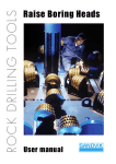
1
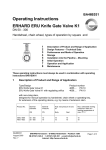
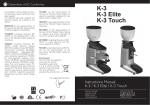
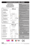
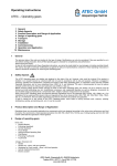
BA46E040
Operating Instructions
ERU Knife Gate Valve K1
DN 350 - 600
______________________________________________________________________
1
2
3
4
5
6
7
8
9
10
11
12
13
General
Safety Aspects
Design Features and Range of Application
Performance, Mode of operation
Transport
Installation into the pipeline
Commissioning
Inadmissible Modes of Operation
Storage
Maintenance
Design with mounted electric actuator
Design with mounted piston actuator
Parts lists and drawings
______________________________________________________________________
1
General
The technical data of the order are binding for the type of design. Modifications can
only be considered if they are specified to us in time before starting production.
Every ERHARD valve is checked for completeness, performance, and tightness
before leaving the factory.
In case of non-compliance with these Operating Instructions, we cannot be made
liable for any damages or troubles resulting thereof. We reserve the right to technical
modifications as against the data and representations contained in these Operating
Instructions in case this should be necessary for improving the valves.
2
Safety Aspects
ERHARD valves and penstocks are reliable and designed to the state of the art.
However, these valves can be a danger when handled by untrained staff in an inexpert
manner or when they are not used in accordance with their duty and purpose.
Whoever in the user’s works is engaged in mounting, dismantling or remounting,
operation and service (inspection, maintenance, repair) of the valves, is supposed to
have read and understood the complete Operating Instructions. The user is
recommended to have the persons involved confirm this fact in writing in each
particular case.
BA46E040
Issue 11/02
Rev. 2
Erhard GmbH & Co D-89502 Heidenheim Postfach 1280
Phone (07321) 320 0 Fax (07321) 320 491
Page 1/19
Operating Instructions ERU Knife Gate Valve K1 DN 350 - 600
______________________________________________________________________
If no competent staff is available for such a work, an expert fitter from the manufacturer
has to be charged with it.
When using the valves, observe the approved technical rules, e.g. DIN standards,
DVGW prints, VDI rules, VDMA standards, etc. For valves which must be supervised,
relevant laws and regulations, e.g. trading regulations, regulations for prevention of
accidents, steam boiler regulations, regulations for gas mains under high pressure,
regulations for combustible liquids as well as technical regulation works TRD, SR, TRG,
TRbF, TRGL, TRAC, UVV, AD instructions etc. are applicable as well as the local safety
regulations and rules for prevention of accidents.
Before removing safety devices and/or carrying out work on the valve or penstock, the
pipe section must be made pressureless and harmless, e.g. by closing the valves and
emptying the pipes. Unauthorized, erroneous and unexpected operation of the valve
has to be avoided.
If work is carried out in the vicinity of the valve or penstock, which leads to soiling
(concrete work, masonry, painting, sandblasting), the valve or penstock must be
covered effectively.
In case, according to the safety regulations for technical equipment (DIN
31000 and following) as well as the relevant rules for prevention of accidents
(UVV), it is necessary to restrict the access to the moving range of the weightloaded levers.
Access to the moving range of the valve gate of ERU Knife Gate Valves K1
with piston or electric actuator has to be restricted by protection devices.
Effective protective devices have to be installed by the customer.
On request, we will supply suitable protective covers.
3
Design Features and Range of Application
3.1. Type and design
3.1.1 ERU Knife Gate Valve K1
according to drawing 3E 60 795
with non-rising stem
Designed for operating devices, e.g. handwheel, extension stem, chain wheel drive,
operating key
Prod. No.: 4605 .... PN 4
4615 .... PN 6
4655 .... PN 10
3.1.2 ERU Knife Gate Valve K1
acc. to drawings 3E 60 796 and 3E 60 797
with rising stem
Designed for automatic operation by means of piston or electric actuator.
Prod. No.: 4607 .... PN 4
4617 .... PN 6
4657 .... PN 10
BA46E040
Issue 11/02
Rev. 2
Erhard GmbH & Co D-89502 Heidenheim Postfach 1280
Phone (07321) 320 0 Fax (07321) 320 491
Page 2/19
Operating Instructions ERU Knife Gate Valve K1 DN 350 - 600
______________________________________________________________________
3.2 Range of application
ERU Knife Gate Valves K1 are wafer-type single door gate valves with short-face-to-face
dimension according to EN 558-1, basic series 20 (former DIN 3202, part 3, series K1).
ERU Knife Gate Valves K1 are suitable for “ON-OFF” operation. If they are equipped
with a regulating orifice, ERU Knife Gate Valves K1 are also suitable for regulating
purposes.
Nom. size
DN
350
400 - 600
400 - 600
4
Nom.press. Hydrostat. test pressure
PN
for
Body
Seat
10
6
4
15
9
6
10
6
4
Max. admissible working
pressure in bars at a working
temperature of max. 80° C
Prod. No.
10
4655....; 4657....
6
4615....; 4617....
4
4605....; 4607....
Performance, Mode of Operation
The solid gate slides between the two body components. It seals on its periphery
against a steel-reinforced elastomer U-shaped profile. The front sides of the gate are
ensured to the outside on both sides by means of readjustable transverse seals.
The gate valves are tested for tightness and resistance to DIN EN 12266 and DIN EN
1074 at the manufacturer’s plant. They are tight in both flow directions.
5
Transport
Transport has to be carried out carefully. Inexpert handling may cause damages to the
valve. Prior to mounting, such damages are to be repaired in an appropriate manner.
Valves too heavy to be handled manually have to be transported by means of lifting
gears suitable for the weight involved, e.g. broad belts. They have to be placed around
the body, e.g. between the two connecting flanges. Valves with eyebolts or lugs have
to be suspended at these devices in an appropriate manner.
It is not allowed to attach the lifting gears to the handwheel, the stem, the gearbox
case or to the flange holes which would be contrary to the relevant safety regulations.
6
Installation into the pipeline
Remove all packing material from the valve. Prior to installation, check the pipeline
for impurities and foreign bodies and clean it if necessary.
ATTENTION: For valves with an arrow showing the flow direction, this direction must
be observed! It is important that all around the valve there is free access for
operation and maintenance. For outdoor installation, the customer has to protect the
valve against the direct effects of the weather.
BA46E040
Issue 11/02
Rev. 2
Erhard GmbH & Co D-89502 Heidenheim Postfach 1280
Phone (07321) 320 0 Fax (07321) 320 491
Page 3/19
Operating Instructions ERU Knife Gate Valve K1 DN 350 - 600
______________________________________________________________________
During installation of the valve, the distance between the pipe flanges should exceed
the valve face-to-face dimension by at least 20 mm. Thus, the raised faces will not be
damaged and the gaskets can be inserted. Steel-reinforced rubber seals are
recommended for use as flange gaskets (consider resistance to flow medium and
temperature).
The mating pipe flanges must be plain-parallel and concentric.
Tighten the connecting bolts evenly (without distortion) and crosswise. The pipeline
mustn’t by any means be pulled up to the valve.
If the distance between the flanges is too large for the valve, use thicker gaskets to
cover the difference.
ERU Knife Gate Valves K1 are
a) clamped between two flanges of the pipeline (wafer type) or
b) screwed to the end flange of the pipeline as end-of-line valves.
When installing the valve into the pipeline, the special flange drilling configuration has
to be observed for this type of valve. One part of the screws connects the pipe flange
with the body. The other part is placed along the body from pipe flange to pipe flange.
7
Commissioning
Prior to commissioning the stem and the stem nut have to be greased.
(Recommended lubricant: see Section 10 “Maintenance”)
After installation, check the valve for smooth operation and move it over the whole
travel (OPEN-CLOSED) by means of the operating gear.
(Attention: When valve is equipped with electric actuator, see also Section 11 “Design
with mounted electric actuator” and Section 11.2 “Commissioning of the Electric
Actuator”).
When valve is equipped with handwheel, the valve gate touches the bearing hub in
open position.
For design with electric actuator or piston actuator a clearance will remain visible
(after-running).
The transverse seals have been set (pre-loaded) to the nominal pressure at the
factory. They can be adjusted to the actual operating pressure: By slackening the
counternuts and bolts the preload of the seal is reduced.
CAUTION ! Flow medium may escape. Wherever toxic or caustic fluids are
handled, wear protective clothing (goggles).
As soon as any slight leakage is discovered, make the transverse seals tight by
uniformly tightening the bolts.
Firmly tighten counternuts. By this adaptation to the actual operating conditions the
operating force is reduced and the service life of the transverse seal is increased.
If disturbing sluggishness of motion continues to be noticed, check whether the valve
has been compressed too hard between the flanges of the pipeline. Slacken the fulllength flange bolts evenly and re-check smooth operation of each one.
See also Section "Trouble-shooting by customer”.
BA46E040
Issue 11/02
Rev. 2
Erhard GmbH & Co D-89502 Heidenheim Postfach 1280
Phone (07321) 320 0 Fax (07321) 320 491
Page 4/19
Operating Instructions ERU Knife Gate Valve K1 DN 350 - 600
______________________________________________________________________
8
Inadmissible Modes of Operation
For inspection or maintenance work the valve - or parts of it - may only be
dismantled if the pipe section in which it is installed has been isolated and made
pressureless. If work is carried out in the vicinity of the valves, leading to soiling
(concrete work, masonry, painting, sandblasting) the valves have to be covered
effectively.
If the ERU Knife Gate Valves K1 are equipped with EPDM profile seals, the EPDM
parts must not come into contact with oil or grease since EPDM swells. For the
recommended lubricant see Section “Maintenance”.
ERU Knife Gate Valves K1 of this type are not suitable for regulating service. For
explicitly regulating operation use special types, e.g. with regulating orifice.
Extending the operating elements by, for example, levers or similar items is not
allowed, danger of damage!
Jogging operation with ERU Knife Gate Valves K1 with electric actuator is not
allowed in end position or if objects are jammed in the pipeline.
9
Storage
Do not store the valves outdoors. During the storage period, the valves have to be
protected against outside influences and impurities, e.g. by covering them with a
tarpaulin. Store valves standing on their feet. Store valves without feet flat on their
connecting flange by means of intermediate boards.
If long-time storage is required, the place of storage should be selected in such a way
that the following conditions are met: frost-protected - cool - dry - dust-free - dark (for
elastomer UV-light is inadmissible). If it is impossible to comply with these conditions,
the valves must be packed to meet these requirements, e.g. they have to be welded in
dark foil.
Store ERU Knife Gate Valves K1 in closed position. Rubber-coated components, as
e.g. the U-shaped sealing element between the body parts, have to be protected
against direct solar radiation. Avoid the effects of radiant heat, e.g. from radiators.
10 Maintenance
ERU Knife Gate Valves K1 should be moved regularly at short intervals (every half
year) over the whole travel (OPEN-CLOSED). Depending on the flow medium and
the local conditions at the site of application, the maintenance interval must be
reduced or may be extended. If a leakage is then found at the gate seal, uniformly
re-tension the screws of the transverse seal on both sides (see “Commissioning”).
Should it no longer be possible to retighten the transverse seal, replace these
sealing elements. For installation see special repair instructions.
BA46E040
Issue 11/02
Rev. 2
Erhard GmbH & Co D-89502 Heidenheim Postfach 1280
Phone (07321) 320 0 Fax (07321) 320 491
Page 5/19
Operating Instructions ERU Knife Gate Valve K1 DN 350 - 600
______________________________________________________________________
Examine valve gate and stem regularly for contamination, clean if necessary and
treat with lubricant (rub-in a thin layer).
Depending on the installation conditions, regularly regrease ERHARD Knife Gate
Valves K1 which are equipped with grease nipples in the area of the stem bearing
assembly.
Recommended lubricant:
KLÜBERSYNTH VR69-252
Messrs. Klüber Lubrication, Munich
10.2 Trouble-shooting by customer:
Trouble
Leakage at the
gate end-face
Possible Causes
Too little preloading
Possibly higher operating
pressure than set
Wearing of the PTFE
packing cords
Contamination (deposit)
on the gate
Preloading of the upper
body screws
Leakage at the
body periphery
Preloading of the body
screws
Leakage at the
transverse seal
Leakage in the
closed position
Excessive
operating forces
Operation
blocked
BA46E040
Issue 11/02
Rev. 2
Remedy
Readjustment of the transverse seal: see
Section "7. Commissioning”.
Replace packing cords
With valve in open position: clean and grease
gate on both sides
Retighten body screws on built-in valve
First of all tighten full-length screws from flange
to flange and, as far as within reach, body
screws. If this does not prove to be successful,
replace U-shaped sealing element.
Contamination of the gate Clean and grease gate
Replace U-shaped sealing element.
Defective U-shaped
sealing element.
Seizing of the gate on
Slacken preloading of transverse seal on both
one side
sides. Pre-load anew uniformly on both sides so
that the gate moves centrically.
Excessive preloading of
Slacken transverse seal,
transverse seal
see "Commissioning".
Contamination (deposit)
With open gate valve: clean and grease the gate
on the gate
on both sides
Regrease thread.
Threaded bush or stem
collar running dry.
Regrease at the grease nipple.
Collar bush and stem
collar bearing
Residues of flow medium
are hardened
Pipe section pressureless. Clean and grease all
accessible surfaces of gate and stem. Slacken
transverse seal on both sides. Slightly unscrew
upper body screws. Knock at the valve with a
rubber mallet trying to operate the valve. If you
are not successful: remove, dismantle, clean,
replace damaged parts.
Erhard GmbH & Co D-89502 Heidenheim Postfach 1280
Phone (07321) 320 0 Fax (07321) 320 491
Page 6/19
Operating Instructions ERU Knife Gate Valve K1 DN 350 - 600
______________________________________________________________________
11 Design with mounted electric actuator
Type:
Prod. No.:
with rising stem
4607 ..12
4617 ..12
4657 ..12
acc. to drawing 3E 60 796
The instructions of Sections 2 to 10 of these Operating Instructions are applicable.
The electric actuator is concentrically mounted on the yoke of the ERU Knife Gate
Valve K1. The stem of the knife gate valve is moved in vertical direction (OPENCLOSED) by means of the threaded bush of the electric actuator. The standard type of
the ERU Knife Gate Valve K1 electric actuator's are equipped with:
Torque and travel switches with 1 break and 1 make contact for each direction of
rotation
Blinker contact for indication of motor operation
Heating in the switchgear compartment
Thermal switch in the motor winding
ERU Knife Gate Valve K1 are switched-off in a travel-dependent way in both limit
positions.
The switching points of the travel limit switches are set during the factory tightness test
at pressure rating in such a way that the setting avoids the gate's clamping or running
against the upper mechanical limit stop of the yoke due to motor after-running. The
torque switches act as safety switches, e.g., in intermediate positions.
If the valve is supplied without mounted electric actuator, the travel limit switches have
to be set after mounting the electric actuator.
See Section 11.2 "Commissioning of Electric Actuator"
Section "Resetting the travel switches".
Please observe the relevant safety rules (VDE/TAB etc.) and the instructions of the
electric actuator's manufacturer concerning transport, storage and commissioning.
Electrical connection has to be effected according to Operating Instructions as well as
wiring and terminal diagrams of the electric actuator's manufacturer (travel, torque and
thermal switches, heating, motor). Before installation, the insulating resistance of the
motor must be measured. If it is lower than 500 K-ohms, this shows that the winding is
moist. The motor has to be removed in order to be dried up and it must be heated by
means of a hot-air fan or in a heating chamber: max. admissible temperature 100°C.
11.1 Jogging and emergency-hand operation
Attention:
If a foreign body is jammed in when operating the valve, the torque switch for the
corresponding direction responds and switches off the motor.
The time lag between response of the torque switch and disconnection of the motor
from the network depends on the signal delay. If another closing order is given in the
original direction, without having moved the valve sufficiently in the opposite direction,
BA46E040
Issue 11/02
Rev. 2
Erhard GmbH & Co D-89502 Heidenheim Postfach 1280
Phone (07321) 320 0 Fax (07321) 320 491
Page 7/19
Operating Instructions ERU Knife Gate Valve K1 DN 350 - 600
______________________________________________________________________
the torque will increase. If this procedure is repeated several times, the torque will
accumulate. The valve and its operating elements are not designed for such an
emergency and might be damaged.
We explicitly draw your attention to the fact that such "jogging operation" is
inadmissible.
Jogging operating is admissible under the following conditions:
If the torque switch responds in intermediate position, the valve must first be moved in
the opposite direction until the torque switch completely returns to its original position.
Only now the valve may be moved again in the direction in which the disturbance
occurred. Proceeding this way, you will obtain torques corresponding to the torques
set at the torque switch. Moreover, the foreign matter can come off and be flushed out
of the seating zone.
Operation by emergency handwheel:
If the valve is operated by means of the handwheel of the electric actuator, the torque
switches do not provide any safety function.
If a foreign body is jammed with the valve being in intermediate position, excessive
operating force - particularly in case of high gear reduction - might be damaging to the
drive components. Therefore, we draw your attention to the following fact:
If any resistance is detected during emergency handwheel operation, some turns must
be made in the opposite direction before the handwheel is turned again in the direction
in which the disturbance occurred (flush out the foreign body). Continue operation with
utmost care, in no case using excessive force. If need be, repeat flushing operation.
11.2 Commissioning of the Electric Actuator
For commissioning the valve the Operating Instructions of the electric actuator's
manufacturer are applicable, too.
1. Move the ERU Knife Gate Valve K1 manually to intermediate position.
2. Check the gate movement and thus the direction of rotation of the actuator by
short electrical starting.
Valve is closing = CLOCKWISE direction of actuator rotation
Valve is opening = ANTI-CLOCKWISE direction of actuator rotation
3. In case of wrong direction of rotation, change poles of motor connection.
4. Check direction of rotation by short electrical starting.
5. Check correct switching sequence of the torque switches in "Open-Close" direction
by manual operation.
6. Change poles if necessary.
7. Move the valve over the whole travel only if the direction of rotation for closing the
valve is CLOCKWISE.
In case of wrong direction of rotation, travel and torque switches are ineffective!
Resetting the travel switches:
BA46E040
Issue 11/02
Rev. 2
Erhard GmbH & Co D-89502 Heidenheim Postfach 1280
Phone (07321) 320 0 Fax (07321) 320 491
Page 8/19
Operating Instructions ERU Knife Gate Valve K1 DN 350 - 600
______________________________________________________________________
1. Move the valve manually into "OPEN" end position.
2. Return by a travel of approx. 5mm.
3. Adjust the "OPEN" travel switch according to the Operating Instructions of the
electric actuator's manufacturer.
4. Move the valve manually into "Closed" end position.
5. Adjust the "CLOSED" travel switch according to the Operating Instructions of the
electric actuator's manufacturer.
If these measures proposed by us are not observed, we cannot be made liable
for any damages resulting thereof.
12 Design with mounted piston actuator (double-acting)
Type:
Prod. No.:
with piston rod
4607 ..20
4617 ..20
4657 ..20
acc. to drawing 3E 60 797
The instructions of Sections 2 to 10 of these Operating Instructions are applicable.
The piston actuator is concentrically mounted on the yoke of the ERU Knife Gate
Valve K1. By means of the piston rod the pressurized piston moves the gate in vertical
direction (OPEN-CLOSED).
The end positions are limited by stop of the piston (piston nuts) at the mounting flange
or cylinder cover. The piston actuator is suitable for compressed air, compressed
water, and compressed oil. If compressed water is used, more maintenance is
necessary due to the properties of the water.
For change-over (Open-Closed), we recommend to use manually or
electromagnetically operated 5/2-way valves. The outlets of these valves have to be
equipped with throttles so that the operating speed can be controlled or adapted to the
operating conditions.
Operating limits for the standard type
DN
350
400
500
600
BA46E040
Issue 11/02
Rev. 2
Max. working
pressure (bar)
PN
Required
supply
pressure
(bar)
P
Max. working
pressure (bar)
PN
Required
supply
pressure
(bar)
P
Max. working
pressure (bar)
PN
Required
supply
pressure
(bar)
P
4
4
4
5-6
5-6
5-6
6
6
6
6-8
6-8
6-8
10
10
10
10
6-8
8
8
8
Erhard GmbH & Co D-89502 Heidenheim Postfach 1280
Phone (07321) 320 0 Fax (07321) 320 491
Page 9/19
Operating Instructions ERU Knife Gate Valve K1 DN 350 - 600
______________________________________________________________________
13 Parts Lists and Drawings
In column "E/V" the parts are marked as follows:
• Spare parts or sets of spare parts, e.g. E1 = spare part set No. 1
or
• Wearing parts or sets of wearing parts, e.g. V1 = wearing-part set No. 1
Parts List for drawing: 3E 60795
ERU Knife Gate Valve K1 with chain-wheel drive, handwheel, square muff, square cap
Part Description
1
Body component
2
U-shaped sealing
element, complete
3
Straight pin
4
Compressor
5
Packing cord, square
6
Profile rubber
7
Gate
8
Washer
9
Hexagon screw
10 Hexagon nut
11 Hexagon screw
12 Hexagon nut
13
14
15
16
17
18
19
Washer
Stem nut
Hexagon screw
Stud bolt
Bearing hub
Scraper ring
Axial grooved ball
bearing
Qty.
2
1
*)
2
4
2
1
*)
*)
*)
*)
*)
*)
1
2
4
1
2
2
E/V
V1
V1
V1
E
V
Part Description
20 Stem
21 Flanged bearing
22
23
24
25
26
27
28
29
30
31
32
33
34
35
36
37
38
Bush
Washer
Hexagon screw
Washer
Hexagon nut
Handwheel
Washer
Hexagon screw
Square cap
Close-tolerance
grooved pin
Square muff
Straight grooved pin
Chain wheel
Chain guide
Collar washer
Straight grooved pin
Hexagon screw
Qty.
1
1
E/V
E
1
3
3
4
4
1
1
1
1
1
1
2
1
1
1
1
1
*) quantity is variable depending on the nominal diameter DN
DN
350
400
500
600
BA46E040
Issue 11/02
Rev. 2
L
78
102
127
154
H1
905
1002
1250
1428
H2
919
1016
1265
1442
H3
976
1073
1324
1502
H4
927
1024
1277
1455
D1
505
561
666
780
D2
400
400
500
500
D3
342
342
412
412
D4
307
307
377
377
Erhard GmbH & Co D-89502 Heidenheim Postfach 1280
Phone (07321) 320 0 Fax (07321) 320 491
C Sq.cap
26
24
26
24
35
27
35
27
Page 10/19
Operating Instructions ERU Knife Gate Valve K1 DN 350 - 600
______________________________________________________________________
Drawing 3E 60795
ERU Knife Gate Valve K1 with chain-wheel drive, handwheel, square muff, square cap
BA46E040
Issue 11/02
Rev. 2
Erhard GmbH & Co D-89502 Heidenheim Postfach 1280
Phone (07321) 320 0 Fax (07321) 320 491
Page 11/19
Operating Instructions ERU Knife Gate Valve K1 DN 350 - 600
______________________________________________________________________
BA46E040
Issue 11/02
Rev. 2
Erhard GmbH & Co D-89502 Heidenheim Postfach 1280
Phone (07321) 320 0 Fax (07321) 320 491
Page 12/19
Operating Instructions ERU Knife Gate Valve K1 DN 350 - 600
______________________________________________________________________
Parts list for drawing: 3E 60796
ERU Knife Gate Valve K1 with electric actuator
Part Description
1
Body component
2
U-shaped sealing
element, complete
3
Straight pin
4
Compressor
5
Packing cord, square
6
Profile rubber
7
Gate
8
Washer
9
Hexagon screw
10 Hexagon nut
11 Hexagon screw
12 Hexagon nut
Qty.
2
1
E/V
Part Description
13 Washer
14 Yoke
V1
*)
2
4
2
1
*)
*)
*)
*)
*)
15
16
17
18
19
20
21
22
23
V1
V1
Qty.
*)
1
Bush
Stem
Bolt
Locking washer
Washer
Cylindrical screw
Electric actuator
Washer
Cylindrical screw
E/V
1
1
*)
*)
4
4
1
4
4
E
*) quantity is variable depending on the nominal size DN
DN
L
H1
D1
d
350
400
500
600
78
102
127
154
808
908
1118
1322
505
561
666
780
TR 36 x 6-LH
TR 28 x 5-LH
TR 30 x 6-LH
TR 36 x 6-LH
DN
Travel Turns/
Travel
Electric
actuator
350 D 120-A/F10
400 (max. 120 NM) 200
D 200-A/F14 250
(max. 120 NM)
BA46E040
Issue 11/02
Rev. 2
58
80
83
100
Closing/Opening time in seconds at the
D3
E4
E5
E6
E7
H3
EMG
500
600
350
400
500
600
Adjusted
torque Nm
OPEN CLOSED
120
110
120
110
120
110
160
150
following speeds of electr.actuator of N =
2)
1)
16
25
50
80
1226
217
139
108
87
69
43
1426
300
192
150
120
96
60
243 346 129 205 1736
2040
313
375
240
288
156
188
125
150
100
120
63
75
32
40
Erhard GmbH & Co D-89502 Heidenheim Postfach 1280
Phone (07321) 320 0 Fax (07321) 320 491
Page 13/19
Operating Instructions ERU Knife Gate Valve K1 DN 350 - 600
______________________________________________________________________
DN
Electric
actuator
AUMA
D3
E1
E2
E3
H2
Closing/Opening time in seconds at the
following speeds of electr.actuator of N =
2)
1)
32
63
90
16
45
22
1305
350 SA 10.1 - A/10
(max.
120
NM)
200 282 256 247 1405
400
217
158
108
77
55
38
300
218
150
107
76
53
1715
SA14.1-A/F14 315 385 325 285 2075
(max. 250 NM)
313
375
227
273
156
188
111
133
80
95
55
67
500
600
Preferred series
1)
2)
for standard actuator
for regulating actuator
BA46E040
Issue 11/02
Rev. 2
Erhard GmbH & Co D-89502 Heidenheim Postfach 1280
Phone (07321) 320 0 Fax (07321) 320 491
Page 14/19
Operating Instructions ERU Knife Gate Valve K1 DN 350 - 600
______________________________________________________________________
Drawing 3E 60796
ERU Knife Gate Valve K1 with electric actuator
BA46E040
Issue 11/02
Rev. 2
Erhard GmbH & Co D-89502 Heidenheim Postfach 1280
Phone (07321) 320 0 Fax (07321) 320 491
Page 15/19
Operating Instructions ERU Knife Gate Valve K1 DN 350 - 600
______________________________________________________________________
Parts list for drawing: 3E 60797
ERU Knife Gate Valve K1 with piston actuator
Part Description
1
Body component
2
U-shaped sealing
element, complete
3
Straight pin
4
Compressor
5
Packing cord, square
6
Profile rubber
7
Gate
8
Washer
9
Hexagon screw
10 Hexagon nut
11 Hexagon screw
12 Hexagon nut
13 Washer
14 Yoke
15 Bush
16 Mounting flange
17 Collar bush
18 Scraper ring
19 0-ring
Qty.
2
1
*)
2
4
2
1
*)
*)
*)
*)
*)
*)
1
1
1
1
1
1
E/V
V1
V1
V1
Part Description
20 Piston rod
21 Bolt
22
23
24
25
26
27
28
29
30
31
32
33
34
35
36
37
Locking washer
Washer
Cylindrical screw
Washer
Cylindrical screw
Piston nut
Double cup collar A
Centering ring
Gasket
Tube cylinder
Threaded bolt
Sleeve
Cylinder cover
Washer
Hexagon nut
Angular fitting
Qty.
1
*)
E/V
E
*)
4
4
4
4
2
1
1
2
1
8
8
1
8
8
1
V2
*) quantity is variable depending on the nominal size DN
DN
L
350
400
500
600
78
102
127
154
BA46E040
Issue 11/02
Rev. 2
H1
H2
1296 808
1446 908
1756 1118
2095 1322
D1
D2
D3
d1
505
561
666
780
250
250
250
300
335
335
335
395
G 1/2
G 1/2
G 1/2
G 1/2
Cylinder
volume
litres
17.5
19.8
27
38
Erhard GmbH & Co D-89502 Heidenheim Postfach 1280
Phone (07321) 320 0 Fax (07321) 320 491
Page 16/19
V2
V2
Operating Instructions ERU Knife Gate Valve K1 DN 350 - 600
______________________________________________________________________
Drawing 3E 60797
ERU Knife Gate Valve K1 with piston actuator
BA46E040
Issue 11/02
Rev. 2
Erhard GmbH & Co D-89502 Heidenheim Postfach 1280
Phone (07321) 320 0 Fax (07321) 320 491
Page 17/19
Operating Instructions ERU Knife Gate Valve K1 DN 350 - 600
______________________________________________________________________
Drawing 2E 42038
ERU Knife Gate Valve K1 with mounted limit switches Siemens SE1 and Bernstein BEK
BA46E040
Issue 11/02
Rev. 2
Erhard GmbH & Co D-89502 Heidenheim Postfach 1280
Phone (07321) 320 0 Fax (07321) 320 491
Page 18/19
Operating Instructions ERU Knife Gate Valve K1 DN 350 - 600
______________________________________________________________________
DN
350
400
500
600
BA46E040
Issue 11/02
Rev. 2
XSE1
260
210
160
138
XBEK
278
230
180
157
Dimensions XSE1 and XBEK are only
approximate dimensions and are not
binding for safe operation of the limit
switches
Erhard GmbH & Co D-89502 Heidenheim Postfach 1280
Phone (07321) 320 0 Fax (07321) 320 491
Page 19/19