1
5 Connecting to power supply
5 Connecting to power supply
Safety instructions
Voltage supply
5.1 Preparing the connection
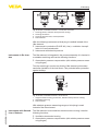
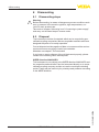
Always keep in mind the following safety instructions:
•
•
Connect only in the complete absence of line voltage
If overvoltage surges are expected, overvoltage arresters should
be installed
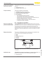
The voltage supply and the signal transmission are carried out via the
four-wire, screened connection cable from the master sensor.
You can find the data for this signal circuit in chapter "Technical data".
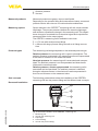
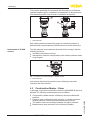
Cable gland ½ NPT
With plastic housing, the NPT cable gland or the Conduit steel tube
must be screwed without grease into the threaded insert.
Max. torque for all housings see chapter "Technical data".
Connection technology
5.2Connecting
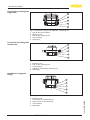
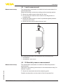
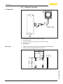
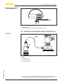
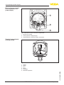
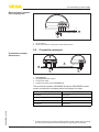
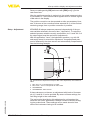
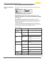
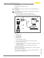
The voltage supply and signal output are connected via the springloaded terminals in the housing.
The connection to the display and adjustment module or to the interface adapter is carried out via contact pins in the housing.
Information:
The terminal block is pluggable and can be removed from the
electronics. To do this, lift the terminal block with a small screwdriver
and pull it out. When reinserting the terminal block, you should hear it
snap in.
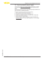
Connection procedure
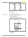
Proceed as follows:
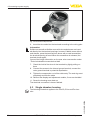
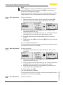
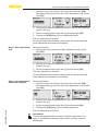
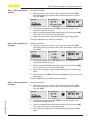
1. Unscrew the housing cover
2. If a display and adjustment module is installed, remove it by turning it slightly to the left.
3. Loosen compression nut of the cable entry
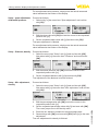
4. Remove approx. 10 cm (4 in) of the cable mantle, strip approx.
1 cm (0.4 in) of insulation from the ends of the individual wires
45050-EN-131011
5. Insert the cable into the sensor through the cable entry
VEGABAR 82 • Slave sensor for electronic differential pressure
21