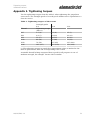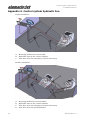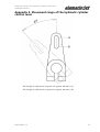
1
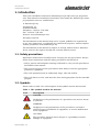
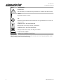
Installation Manual
Table of contents
Installation Manual
Table of contents
1. Introduction .................................................................................................. 1
1.1. Safety precautions ............................................................................. 1
1.2. Symbols ............................................................................................. 1
2. General description of installation ............................................................... 3
3. Installation Methods .................................................................................... 5
3.1. Repowering installation ..................................................................... 7
3.1.1. Reinforced plastic mounting template .................................... 7
3.1.2. Aluminium mounting template .............................................. 12
3.2. Installation out of the mould ........................................................... 12
3.2.1. Removable mounting template mould ................................... 13
3.2.2. Fixed mounting template ...................................................... 14
4. Attaching the propulsion unit .................................................................... 17
4.1. Preparations .................................................................................... 17
4.2. Attaching the body .......................................................................... 18
4.3. Installing the lubrication system for the bearing ............................ 20
4.3.1. Front bearing ........................................................................ 20
4.3.2. Rear bearing ......................................................................... 22
4.4. Attaching the hydraulic cylinders .................................................... 25
4.5. Attaching the hydraulic pump ......................................................... 28
4.6. Oil cooling ....................................................................................... 30
4.7. Attaching the grass rake ................................................................. 31
4.8. Installing the raw water cooling line .............................................. 32
4.9. Installing the inspection hatch elevation collar ............................... 34
5. Installing the control system ..................................................................... 37
5.1. Connecting the reversing deflector to the control system ............... 37
5.1.1. Connecting the control cables .............................................. 40
5.1.2. Cylinder adjustment .............................................................. 41
5.2. Connecting the steering nozzle to the control system ..................... 43
6. Engine installation ..................................................................................... 47
7. Antifouling .................................................................................................. 49
Appendix 1. Grease recommendations ........................................................... 51
Appendix 2. Oil recommendations ................................................................. 52
Appendix 3. Tightening torques ..................................................................... 53
Appendix 4. Control system hydraulic line .................................................... 54
Appendix 5. Movement range of the hydraulic cylinder control lever ........... 55
AM/245/EN/1.1.0
iii
Introduction
Installation Manual
1. Introduction
This is the installation manual for Alamarin-Jet's Jet-245 water jet propulsion
unit. This manual is intended for mechanics who install the Alamarin-Jet water
jet propulsion unit to a suitable boat.
© Alamarin-Jet Oy
Tuomisentie 16
FI-62300 Härmä
Telephone: +358 10 7745 260
Fax: +358 10 7745 269
Internet: www.alamarinjet.com
All rights reserved.
The information in this manual may not be copied, published or reproduced
in any way whatsoever, or exploited for commercial purposes, without explicit
written permission from Alamarin-Jet Oy.
The information in this manual is subject to change without notice. AlamarinJet Oy reserves the right to modify the contents without notice.
1.1. Safety precautions
Read these instructions carefully before carrying out any procedures. Always
follow these instructions and the safety precautions shown below.
• Only a person with adequate training is allowed to carry out the procedures
described in this manual.
• The person carrying out the procedures must always wear the appropriate
protective equipment.
• The work premises must be sufficiently large, safe and well-lit.
• The tools that are to be used must be clean and appropriate for the intended
purpose.
1.2. Symbols
Please refer to table 1 for a description of the symbols used in this manual.
Table 1. The symbols used in the manual
Icon
Description
DANGER
Negligence in the performance of a procedure can cause a threat
to your life.
WARNING
Negligence in the performance of the procedures can lead to
personal injury, breakdown of equipment, or serious malfunction
of the equipment.
CAUTION
The procedure involves minor danger or a possibility of minor
damage to equipment.
AM/245/EN/1.1.0
1
Introduction
Installation Manual
Icon
Description
WARRANTY
The warranty is voided if the procedure is carried out incorrectly.
NOTE
Important notice or fact.
TIP
Additional information that facilitates the performance of work or
a procedure.
CARRIED OUT BY ONE PERSON
One person can carry out the procedure.
CARRIED OUT BY TWO PERSONS
Two persons must carry out the procedure.
INDICATOR ARROW
ARROW DESCRIBING MOTION
Please note that this instruction uses the terms "jet" and "jet propulsion unit".
They mainly refer to the same thing.
2
AM/245/EN/1.1.0
General description of installation
Installation Manual
2. General description of installation
Alamarin-Jet water jet propulsion units can be installed on a reinforced plastic,
aluminium, steel, polyethylene, or wooden boat.
Perform the installation in the following order:
1.
Attach the mounting template to the boat's hull (section 3. Installation
Methods, page 5).
2.
Attach the propulsion unit to the mounting template (section 4. Attaching
the propulsion unit, page 17).
3.
Install the control system (section 5. Installing the control system, page
37).
4.
Install the engine (section 6. Engine installation, page 47).
5.
Paint the propulsion unit with antifouling paint (section 7. Antifouling, page
49).
This is only necessary if the boat is used in waterways where organisms
are likely to attach themselves to the propulsion unit.
AM/245/EN/1.1.0
3
General description of installation
Installation Manual
4
AM/245/EN/1.1.0
Installation Methods
Installation Manual
3. Installation Methods
The Alamarin-Jet water jet propulsion unit is installed on the boat using a
mounting template. Several mounting templates are available, depending on
the installation methods and materials used.
For combi-frames, there are two primary installation methods available:
a)
”short tail”, which minimises the installation length outside the stern
b) ”long tail”, which minimises the installation length inside the stern
Both methods have their advantages, and it is up to the boat designer to
decide which method is best suited for each boat.
Short tail installation
This installation method minimises the installation length of the jet outside
the boat. At the same time, the jet's inspection hatch ends up inside the boat,
which makes it safer to clean the intake duct in rough seas.
Figure 1. Short tail installation
Long tail installation
This installation method minimises the installation length of the jet inside the
boat so the engine can be installed closer to the stern of the boat. The jet's
inspection hatch ends up outside the boat, which reduces the risk of sinking
due to a water leak.
AM/245/EN/1.1.0
5
Installation Methods
Installation Manual
Figure 2. Long tail installation
The mounting template can be installed into a hole at the bottom and the stern
of the boat, or the shape of the mounting template can be added to the boat's
template (GRP boats).
The correct positioning of the mounting template is crucial since it determines
the position of the jet. Figure 3 shows the edge of the jet that should be
parallel to the keel. When the edge is correctly aligned parallel to the keel,
the jet pushes the boat forward with the optimal thrust angle (4 degrees). The
main shaft of the propulsion unit then slants 4º downwards by reference to
the keel. If the design of the boat requires a different thrust angle, the matter
must be handled and arranged with Alamarin-Jet Oy.
Figure 3. Thrust angle
6
AM/245/EN/1.1.0
Installation Methods
Installation Manual
Figure 4. Aluminium mounting templates
3.1. Repowering installation
The repowering installation method is used in the propulsion system's
modification installation. In addition, it is an appropriate installation method
for prototype or one-off boats. In aluminium boats, the propulsion unit is
always installed using the repowering principle.
For attaching the mounting template, a hole of an appropriate size is cut in
the stern and the bottom of the boat, in which the mounting template is either
laminated or welded.
3.1.1. Reinforced plastic mounting template
If the installation is done on a boat that has previously had some other type
of rear propulsion unit, make sure that the engine's installation supports do
not impede laminating. There must be at least 150 mm of free hull surface
on all sides of the mounting template, on which the mounting template can
be laminated (figure 5) The same 150 mm requirement applies to all boats,
including new ones.
Figure 5. Repowering installation
AM/245/EN/1.1.0
7
Installation Methods
Installation Manual
Hull and stern laminate must be dry and clean before work can be
commenced.
Cutting and attaching the mounting template:
1.
Make a hole at the bottom and the stern of the boat for the mounting
template. The mounting template should be positioned slightly over
the stern of the boat. The excess part can be cut away after installation
(figures 6 and 7, point A).
The gap between the mounting template and the hull should be fitted so
that it is as small as possible.
2.
The front of the mounting template is fitted to a v-bottom boat with the use
of a triangular plate having a length of approximately 600 mm from the
keel.
Figure 6. Positioning of the mounting template, "short tail"
Figure 7. Positioning of the mounting template, "long tail"
A
8
Collar to be cut off
AM/245/EN/1.1.0
Installation Methods
Installation Manual
B
V-bottom adaptor plate
Figure 8. V-bottom adaptor plate
3.
Chamfer the edges of the hole on the bottom and stern of the boat.
The chamfered part must be 150 mm wide and the hole edge thickness
must be 3 mm.
If the boat's hull is made of sandwich laminate, first remove 100 mm of
core material round the hole and then chamfer the core material as well as
about 100 mm of the exterior surface. Slightly chamfer the inner envelope.
4.
Fit the mounting template in place and support it from the outside.
NOTE!
The lower surface of the mounting template must be level
with the bottom of the boat (figure 9).
The edge of the mounting template must be parallel with
the boat's keel (= the edge of the hole).
If this is not the case, the propulsion unit thrusts the boat
in the wrong angle and performance is lowered.
AM/245/EN/1.1.0
9
Installation Methods
Installation Manual
Figure 9. Cross-section of the mounting template
Figure 10. Mounting template alignment
A The edge of the mounting template parallel to the keel
10
5.
Close the seam with tape from the outside.
6.
Run gelcoat paint onto the seam from above until it is filled.
7.
Laminate 100 mm-wide carpet strips on the seam.
8.
Continue laminating over the whole mounting template and the chamfers
until the final thickness of 15 mm is reached.
AM/245/EN/1.1.0
Installation Methods
Installation Manual
Figure 11. Laminating
A Boat shell laminate
B Attachment laminate
C Mounting template laminate
D Seam
E Original gelcoat
F Seam-filling gelcoat
9.
Fit engine supports and possible bracings.
10. Cut off the excess collar on the mounting template outside the stern
(figure 12).
Figure 12. Excess collar
AM/245/EN/1.1.0
11
Installation Methods
Installation Manual
11. Smooth the seams and paint the visible reinforced plastic surfaces with
topcoat paint.
This is important because an uncovered laminate absorbs water.
3.1.2. Aluminium mounting template
1.
Cut a hole of appropriate size in the bottom and the stern of the boat.
In a long tail installation, the collar of the mounting template covers
the inner surface of the stern and the excess material must be cut after
installation (figure 13). In a short tail installation, the excess collar is
outside the stern (figure 6)
Figure 13. Long tail aluminium mounting template
The gap between the mounting template and the hull should be fitted so
that it is as small as possible.
2.
Chamfer the plate edges as required by general welding standards.
3.
Fit the mounting template in place.
4.
Weld the mounting template in place both on the inside and the outside,
and make the seam watertight.
5.
Abrade the welded seams so that they are smooth at the bottom area.
Any uneven spots at the bottom must be trimmed by caulking, for example.
6.
Paint the mounting template with paint that is suitable for painting
aluminium.
Follow the paint manufacturer's instructions.
The material of the plate section: AlMg3
Welding filler metal: AlMg5
3.2. Installation out of the mould
12
AM/245/EN/1.1.0
Installation Methods
Installation Manual
If you want to produce one type of boat with several varying propulsion unit
options, it is possible to make a mould of the mounting template and fit it
to the standard hull mould (figure 14). This speeds up installation of the
propulsion unit without adding to mould expenses.
The mould for the mounting template is made from a mounting template
provided by Alamarin-Jet Oy. In double installations, two moulds must be
made, one for each side of the hull.
CAUTION!
Prepare the mounting template to fit exactly in the boat's
mould. This must be done carefully, as inaccuracies (bulges)
are copied to the final boat and result in deterioration of boat
performance.
Figure 14. Making a negative of the mounting template
3.2.1. Removable mounting template mould
If you use a removable mounting template mould, you can use the boat's hull
mould in both jet installation and rear propulsion unit installation. There are
three stages in preparing and installing a removable mounting template:
1.
Make a negative (mould) of the mounting template.
2.
Process the mould to fit the boat mould exactly.
3.
Install the negative onto the boat's mould.
Follow these instructions:
Fitting the mounting template onto the stern of the boat requires care. In
double installations in particular, the angled cutting of the slanted stern
requires precision.
AM/245/EN/1.1.0
13
Installation Methods
Installation Manual
Figure 15. Cutting the collar (double installation)
The edges of the mounting template must be smoothed so that the end product
shows no big notches.
Reinforce the mounting template negative with a wooden frame, plywood
plate or, for example, urethane foam. This way the collar will not bend inwards
during laminating.
Attach the mounting template mould on to the boat's mould using tape, for
example, so that it stays in place during lamination.
TIP!
It is advisable to mark the location of the mounting template
on the boat mould after the first installation. This makes fitting
the mounting template faster and easier the next time.
CAUTION!
Double installation!
After the boat has been laminated and is ready to be removed
from the mould, the mounting template negatives detach with
the boat. The mounting templates are removed from the boat
for the next installation.
3.2.2. Fixed mounting template
The mounting template can also be fixed to the mould. In this case, the boat's
hull mould can only be used in jet installation. In double installation, the
boat's mould must be in two pieces in order to make separating the mounting
templates possible. A two-piece mould is not necessarily needed for single
installation.
14
AM/245/EN/1.1.0
Installation Methods
Installation Manual
Double installation
1.
Make two negatives of the mounting template.
2.
Fit and install the mounting templates on the boat's mould (section 3.2.1.
Removable mounting template mould, page 13).
3.
Laminate the rear end of the boat in the mould and remove it.
4.
Remove the mounting templates.
5.
Make a separate mould of the rear end.
Single installation
1.
Make a negative of the mounting template.
2.
Fit and install the mounting template on the boat mould (section 3.2.1.
Removable mounting template mould, page 13).
3.
Laminate the hull of the boat in the mould and remove it.
4.
Make a new mould of the hull.
AM/245/EN/1.1.0
15
Installation Methods
Installation Manual
16
AM/245/EN/1.1.0
Attaching the propulsion unit
Installation Manual
4. Attaching the propulsion unit
The propulsion unit is attached to the boat one part at a time. Attachment is
carried out in the following order:
1.
Propulsion unit body
2.
Lubrication system for the bearings
3.
hydraulic cylinders
4.
hydraulic pump
5.
Grass rake
6.
Raw water cooling line
4.1. Preparations
Holes must be made on the installation surface of the mounting template for
attaching the propulsion unit and for the required bushings. An aluminium
mounting template is already equipped with the required holes.
Sawing/drilling the holes is carried out with the drilling templates that come
with delivery.
Drilling the holes:
1.
Set the template against the installation surface so that the texts are
visible, and centre the template in relation to the ready-drilled centre hole.
2.
Mark the holes and drill them.
The gauge has only a centre hole for large holes, and they are drilled to
the right diameter with a hole saw. The name of the bushing and the final
diameter are marked on the template for clarity (figure 16).
TIP!
It is advisable to first make one hole and use it to attach
the drilling template to the stern. This way it stays in place
when drilling the other holes.
AM/245/EN/1.1.0
17
Attaching the propulsion unit
Installation Manual
Figure 16. Drilling template
Before installation, make sure that
1.
The installation surface is straight and clean.
2.
The holes are drilled/sawn correctly.
3.
Stern laminate does not get in the way of the propulsion unit and its
auxiliaries, which means that the laminate is not too thick.
4.
The following parts have been detached from the jet:
Short tail:
• raw water intake
Long tail:
• raw water intake
• hydraulic cylinders
• hydraulic pump
WARNING!
When removing the reversing deflector hydraulic cylinder,
the piston rod must not twist 180°. The cylinder will not
work properly if that occurs.
4.2. Attaching the body
18
AM/245/EN/1.1.0
Attaching the propulsion unit
Installation Manual
Attaching the body of the propulsion unit to the boat:
1.
Spread sealing compound (such as Sikaflex 221) on the fixing area,
depending on which installation method you are using (figure 17, point A).
Figure 17. Surfaces to be sealed
2.
Carefully seal all holes:
3.
Lift the jet into place and push the fastening bolts into their holes if you
have not already done so.
Some of the screws are already attached during jet manufacture. Ask your
assistant in the boat to fasten the nuts.
4.
Tighten the nuts evenly on opposite sides and make sure that sealing
compound squeezes out slightly on every side.
The tightening torque of the screws in reinforced plastic boats is 20 Nm,
which is different from the standard due to its softer base. Standard
fastening is used in aluminium boats.
5.
Wipe the burrs of sealing compound from the outer edges, intake duct and
inside round the holes.
6.
Seal the gaps between the bottom plate of the jet and the hull (figure 18).
AM/245/EN/1.1.0
19
Attaching the propulsion unit
Installation Manual
Figure 18. Sealing the bottom plate
4.3. Installing the lubrication system for the bearing
4.3.1. Front bearing
The front bearing carries the axial and radial loads. The bearing is oillubricated and the housing is secured with mechanical sealing.
When the shaft rotates, the oil circulates through the reservoir and impurities
gather at the bottom of the reservoir on the drain plug magnet (figure 19,
point D).
The oil reservoir included in the system is installed in a suitable place.
The need for maintenance (oil change) must be taken into consideration
when selecting the location. It must be possible to check the oil level when
necessary.
The bearing housing is filled with oil when it is delivered from the factory. The
installation must be carefully performed in accordance with the instructions
so that the lubrication functions well from the beginning and as little air as
possible escapes into the system.
Installing the front bearing housing lubrication:
1.
Attach the front bearing lubricating oil reservoir in a suitable place.
The hoses attached to the reservoir connectors are marked IN and OUT.
The side of the bearing housing has the corresponding markings (Figure
19, A = IN and B = OUT).
20
AM/245/EN/1.1.0
Attaching the propulsion unit
Installation Manual
Figure 19. Bearing housing connectors
2.
Remove the plug from the bearing housing IN connector, push the hose
coming from the reservoir into place, and tighten the joint using pipe
straps.
3.
Pour oil into the reservoir and let the hose fill up for approx. 5 minutes.
The type of oil to use is described in appendix 2. Oil recommendations, page
52.
Keep the hose as straight as possible and shake it occasionally to prevent
air pockets from forming.
4.
Remove the plug from the OUT connector and push the hose into place.
Tighten the joint using pipe straps.
5.
Add oil to the reservoir until the oil level is between the markings on the
dipstick (figure 20, points A and B).
The system generates slight pressure into the return line and the oil starts
to circulate.
AM/245/EN/1.1.0
21
Attaching the propulsion unit
Installation Manual
Figure 20. Oil level in the reservoir
4.3.2. Rear bearing
The rear bearings of the shaft are lubricated from point E on figure 19. The
lubricant flows through the bearing housing and the coupling flange to the
core of the shaft, which has a hole running through it all the way to the rear
bearing housing. Form a line from point E to the grease nipple with a plastic
hose. Alternatively, there can be an automatic lubrication unit at the end of the
hose.
The automatic lubrication unit (figure 21) decreases the need for maintenance
because it feeds grease to the rear bearing each time the jet's main shaft
rotates. The grease going to the rear bearing lubricates the bearing, and
it also prevents water from leaking into the bearing housing. The amount
of grease is adjusted with a screw in the hydraulic cylinder, which tightens
the spring (figure 22). When you loosen the screw, the amount of grease
decreases.
22
AM/245/EN/1.1.0
Attaching the propulsion unit
Installation Manual
Figure 21. Automatic lubrication unit
A
Oil pressure hose from the
hydraulic cylinder
D
Grease nipple
B
Scale
E
Grease hose to the lubrication
channel
C
Piston
Figure 22. Adjusting the automatic lubrication unit
Installing the automatic lubrication unit:
1.
Choose an appropriate place near the propulsion unit.
Note the lengths of the oil pressure hose and the grease hose. The oil
pressure hose (figure 23, point B) must not be tight. Also make sure that
the piston (figure 23, point A) can move freely, as it protrudes the length of
the scale when the reservoir fills up.
AM/245/EN/1.1.0
23
Attaching the propulsion unit
Installation Manual
Figure 23. Automatic lubrication unit's piston movement range
2.
Use the template delivered with the automatic lubrication unit to make
holes for the fastening screws of the rack in a sufficiently sturdy place.
3.
Attach the screws delivered with the automatic lubrication unit into place
nearly all the way.
4.
Put the rack in place.
The rack has slots for the screws. Slide the rack under the screws and
tighten them (figure 24) with a spanner.
Figure 24. Automatic lubrication unit's tightening screws
5.
Screw the oil pressure hose into place (figure 25).
Please note that the cylinder must be rotated slightly before the pressure
hose can be attached. However, if you want to retain the position of the
24
AM/245/EN/1.1.0
Attaching the propulsion unit
Installation Manual
cable clamp, rotate the plate in accordance with the instructions in section
5.1. Connecting the reversing deflector to the control system, page 37.
Figure 25. Attaching the oil pressure hose
6.
Fit the grease hose to the nipple in the body.
Feeding
You can adjust the feed as follows:
• If the automatic lubrication unit feeds too much grease (the reservoir
empties too soon), reduce the pressure by loosening the adjusting screw
(figure 22).
• If the automatic lubrication unit does not feed grease to the rear bearing
(cold conditions, thick grease type), increase the pressure by tightening the
adjusting screw (figure 22).
The amount of grease fed to the rear bearing must be 0.1 l/100 h (6 cu in/100
h). The grease volume in the unit is 0.3 l (18 cu in). With these settings, the
reservoir will empty in 300 hours. If you notice that the reservoir empties
more quickly or slowly than this, adjust the pressure in the desired direction.
You can fill the reservoir by pushing grease into it with a grease gun through
the nipple (figure 21, point D). Then the piston (figure 23, point A) will
protrude out of the reservoir.
The properties of the grease to use are described in appendix 1. Grease
recommendations, page 51.
4.4. Attaching the hydraulic cylinders
The Jet-245 has two hydraulic cylinders, one for the reversing deflector and
one for the steering nozzle. Both cylinders are installed the same way.
1.
Make sure that the cylinders are attached without the sealing compound.
The lock nut (figure 26, point A) must go through the stern so it rests
against the body of the jet.
AM/245/EN/1.1.0
25
Attaching the propulsion unit
Installation Manual
2.
With the cylinder detached, screw the lock nut all the way to the bottom.
3.
Apply sealing compound to the cylinder retaining threads (figure 26, point
B).
Figure 26. Installing the hydraulic cylinders
26
4.
Push the cylinder into place and screw it in until the correct distances
(X=~31 mm and Y=~29 mm) are reached (figure 27).
5.
Tighten the lock nut.
AM/245/EN/1.1.0
Attaching the propulsion unit
Installation Manual
Figure 27. Dimensions of the hydraulic cylinders
6.
Check that the reversing deflector and the steering nozzle move correctly.
The steering nozzle should move the same distance in both ways.
For the reversing deflector, the determining limit is the deflector's bottom
position. Make sure that the deflector's connecting rod does not come into
contact with the cast parts of the jet (figure 28).
If any deviations are observed in the movements of the reversing deflector
or the steering nozzle, adjust the cylinders by screwing them in or out.
AM/245/EN/1.1.0
27
Attaching the propulsion unit
Installation Manual
Figure 28. Reversing deflector connecting rod
4.5. Attaching the hydraulic pump
Attaching the hydraulic pump:
1.
Install the pump rack and the pump with screws to the front surface of the
bearing housing.
Leave the screws slightly loose.
There are a total of four screws, two on each side (figure 29, points A and
B).
28
AM/245/EN/1.1.0
Attaching the propulsion unit
Installation Manual
Figure 29. Attaching the hydraulic pump
2.
Fit the belt in place.
3.
Lift the rack by cranking it from point C indicated in figure 29.
4.
Tighten the screws.
The tightening torque is 46Nm.
5.
Install the pressure hose to connectors D and E (figure 29).
6.
Install the reservoir hose to connector F (figure 29).
7.
Install the oil reservoir and its rack to a suitable place above the pump.
Figure 30. Oil reservoir and rack
AM/245/EN/1.1.0
29
Attaching the propulsion unit
Installation Manual
In Figure 30, the 16 mm (5/8'') connector (A) is intended for the hose that
goes to the pump and the 12 mm (1/2'') connector (B) for the return hose.
Checking the oil level
The system must have the right amount of oil. If you need to add oil to the
system, add it in the oil reservoir through the cap (figure 31, point C). There
is a dipstick on the reservoir cap with markings for maximum and minimum
oil levels (figure 31). The type of oil to use is described in appendix 2. Oil
recommendations, page 52.
Figure 31. Checking the oil level
A
Maximum level
B
Minimum level
C
Cap
4.6. Oil cooling
The oil circulating in the system must be cooled down in order to prevent
excessive heating. This is done with a heat exchanger, which is integrated into
the frame of the propulsion unit (figure 32).
WARRANTY!
If the oil in the system is not cooled, the manufacturer is not
responsible for possible damages which derive directly or
indirectly from the oil overheating.
30
AM/245/EN/1.1.0
Attaching the propulsion unit
Installation Manual
Figure 32. Cooling system
WARNING!
The system has high pressure during use (max. 85 bar (1,200
psi)).
Make sure that the hoses do not rub against sharp edges. The
bursting of a pressure hose can cause serious danger.
4.7. Attaching the grass rake
The grass rake (figure 33) is attached in front of the intake opening with two
screws.
AM/245/EN/1.1.0
31
Attaching the propulsion unit
Installation Manual
Figure 33. Grass rake
Attaching the grass rake:
1.
Seal the fixing area in the same manner as when installing the propulsion
unit body.
2.
Fit the grass rake in place in the intake duct and tighten the screws in
place.
The normal tightening torque for an M8 screw is 23 Nm (17 lb ft). The
tightening torque of the screws in reinforced plastic boats is only 20 Nm
(15 lb ft).
4.8. Installing the raw water cooling line
Cooling water for the engine can be taken from the pressure face of the
propulsion unit. The propulsion unit has one raw water intake as standard for
this purpose. It is located on the starboard side of the bearing housing (figure
34).
32
AM/245/EN/1.1.0
Attaching the propulsion unit
Installation Manual
Figure 34. Raw water intake
The intake has a G3/4" external thread (3/4" BSP). The line to the engine can
be constructed using normal pipe parts or can be plugged into the engine
using the plugs delivered with the propulsion unit. The raw water intake can
also be used for other purposes that require pressure water.
The design pressure of the line is 10 bar, but the actual pressure depends on
the impeller type, running speed and the line structure.
When constructing the raw water cooling line
• Note the engine manufacturer's recommendations regarding the cooling
water feed.
• If necessary, throttle the line sufficiently before the engine and remove the
throttles after the engine.
Line pressure should be measured before the engine, and the pressure should
be adjusted in accordance with the engine manufacturer's instructions.
The hose joints must be durable enough. If the hose breaks or the joint comes
off, the engine room may fill with water, the engine may break, or the boat may
even sink.
Dry running of the jet (when the boat is not in water) can be performed
without restriction.
AM/245/EN/1.1.0
33
Attaching the propulsion unit
Installation Manual
CAUTION!
However, always observe the manufacturers' other
instructions for dry running.
The operation of the raw water line is depicted in figure 35.
Figure 35. Raw water cooling
1
Raw water connector
2
Tap
3
Filter
4
Input for the engine
Note the following when installing the raw water cooling line:
• There must be a shut-off valve at the beginning of the line so that the line
can be cut off when the boat is in water. If there is no valve, water will leak
into the boat when the line is opened for cleaning, for example.
• The filter must be installed on the line before the coolers are installed. The
filter must be above the waterline. (This way water does not flood in when
the filter is being cleaned.)
• The line empties itself when the boat is on a horizontal plane (e.g. when the
boat is hanging on a davit).
WARNING!
If the raw water line is not used at all, the line must be closed
off carefully by means of the plug delivered with the jet.
If the line is not plugged, the engine room will fill with water.
4.9. Installing the inspection hatch elevation collar
In a short tail installation, the inspection hatch is located inside the boat. If
the static waterline (figure 36, point A) ends up higher than the inspection
hatch, the inspection hatch must be equipped with an elevation collar (figure
36, point B). This way, when the inspection hatch is opened, water rises inside
the elevation collar but does not spill out into the engine compartment.
34
AM/245/EN/1.1.0
Attaching the propulsion unit
Installation Manual
WARNING!
Not using an elevation collar when the static waterline is
above the inspection hatch will result in a water leak in the
engine compartment, which will in turn result in immediate
risk of sinking!
Figure 36. Inspection hatch elevation collar
The elevation collar is an accessory that is available to order when required.
The collar is installed using four M5 screws (figure 37), and the coupling is
sealed using a sealing compound.
Figure 37. Installing the elevation collar.
AM/245/EN/1.1.0
35
Attaching the propulsion unit
Installation Manual
36
AM/245/EN/1.1.0
Installing the control system
Installation Manual
5. Installing the control system
The propulsion unit's control system must be installed correctly. Incorrect
installation of the system will reduce performance.
Because the propulsion unit can be used with or without gears, there are
various methods of installation.
Installation Options
• The gear is located between the propulsion unit and the engine.
A control with two levers, one of which controls the gearbox and the
accelerator and the other the reversing deflector.
• Between the propulsion unit and the engine, there is only the intermediate
shaft.
A control with two levers, one of which controls the accelerator and the
other the reversing deflector.
• Two propulsion units with a gear.
Two separate controls with two levers or one control with four levers. The
two adjacent levers are used to control the gears and accelerators of both
engines, and the other two to control the reversing deflectors.
WARNING!
The movement of the reversing deflector must always be
controlled with a separate lever. Otherwise the propulsion unit
does not function correctly.
5.1. Connecting the reversing deflector to the control system
The control cylinder of the reversing deflector is used with the lever (figure
38, point A) at the end of the cylinder. The lever has a cable terminal when it is
delivered from the factory. However, the cable's inlet direction can be different
to the standard direction of the cable support (figure 38, point B). You can turn
the cable support plate to point in the desired direction in accordance with the
cable's inlet direction.
AM/245/EN/1.1.0
37
Installing the control system
Installation Manual
Figure 38. Hydraulic cylinder
Changing the position of the cable support:
1.
If the control cable is attached, detach the end of the cable (figure 38,
point C) from the cylinder's operating lever and detach the cable fastener
from the support plate (figure 38, point D).
2.
Loosen the operating lever's fastening screw and pull the lever off the
shaft (figure 39).
Figure 39. Removing the operating lever
3.
Open the fastening screws (four in total, figure 40) that attach the support
plate to the cylinder.
Note that the same screws attach the valve housing to the cylinder pipe.
However, if you are careful the valve housing will remain in the cylinder
pipe.
38
AM/245/EN/1.1.0
Installing the control system
Installation Manual
Figure 40. Support plate fastening screws
4.
Turn the support plate into the desired position and attach it with screws
to the valve housing (tightening torque: 10 Nm (7 lb ft)).
Check that the support plate or control cable do not interfere with the
rotating intermediate shaft, for example.
The support plate has eight holes, so you can turn the plate at 45°
intervals. In figure 41 the plate has been turned 135°.
Figure 41. Turned support plate
5.
Place the lever (figure 42, point A) on the operating shaft so that it lies
between the limiters on the support plate (figure 42, point B).
The tightening torque of the lever screw is a non-standard 10 Nm (7 lb ft).
AM/245/EN/1.1.0
39
Installing the control system
Installation Manual
Figure 42. Attaching the operating lever
6.
Attach the control cable with a fastener (figure 42, point C) to the support
plate and with an angle joint (figure 42, point D) to the lever ball screw.
The height of the screw attachments at the end of the lever affects the
control system stroke length.
See the cylinder adjustment instructions in section 5.1.2. Cylinder
adjustment, page 41.
5.1.1. Connecting the control cables
The control cables are connected from the control system to the reversing
deflector, as indicated in figures 43–45.
Idle running
Both levers (B and C) are in the centre (figure 43)
Figure 43. Idle running
A
Accelerator
B
Reversing deflector
C
Steering cylinder's operating lever
Full astern
40
AM/245/EN/1.1.0
Installing the control system
Installation Manual
The control lever is down, the cylinder operating lever on the left (figure 44)
Figure 44. Full astern
Full ahead
The control lever is up, the cylinder operating lever on the right (figure 45)
Figure 45. Full ahead
5.1.2. Cylinder adjustment
When you start the engine for the first time, make sure that you have oil
available to add to the reversing deflector control hydraulic system.
Fill the reservoir with oil before you start the engine. After you start the
engine and put it into forward gear, the oil is transferred from the reservoir
into the system and the pump automatically removes air from the system. If
the oil level decreases in the reservoir, add some oil. There is a dipstick in the
reservoir that you can use to check the oil level (figure 31). Occasionally move
the hydraulic cylinder's operating lever back and forth (figure 42, point A) so
that the cylinder fills with oil.
Adjusting the cylinder:
1.
Detach the control cable from the end of the cylinder operating lever
(figure 46, point A).
AM/245/EN/1.1.0
41
Installing the control system
Installation Manual
Figure 46. Removing the control cable
2.
Loosen the operating lever screw (figure 46, point B) but do not pull the
lever off the shaft yet.
3.
Place the lever against the limiter on the shaft (figure 47, point A).
Figure 47. Operating shaft and limiter
4.
Turn on the engine and put it into gear.
5.
Using a wrench, turn the operating shaft (figure 47, point B) 10 mm (0.4")
clockwise so that the reversing deflector is down, blocking the jet flow.
If you turn the shaft too much, it will no longer move smoothly, indicating
that the cylinder has reached the end of its movement range. If this
happens, turn the shaft back slightly.
6.
42
Attach the operating lever to the shaft with a screw and tighten the screw
to a torque of 10 Nm (7 lb ft).
AM/245/EN/1.1.0
Installing the control system
Installation Manual
Do not tighten the screw too much!
7.
Attach the control cable to the screw at the end of the operating lever
(figure 46, point A).
8.
Use the control system in the cabin to check that the deflector can move to
the up and down positions.
In the up position, the deflector does not block the jet flow (figure 48). In
the down position, the top of the reversing deflector nearly touches the
steering nozzle (figure 49).
Figure 48. Deflector in the up position
Figure 49. Deflector in the down position
5.2. Connecting the steering nozzle to the control system
The jet features a compact integrated hydraulic cylinder for steering. The
cylinder is easy to use and enables comfortable steering.
The cylinder is compatible with most steering pumps available on the market.
Compatible pumps are also available from Alamarin-Jet as accessories. The
AM/245/EN/1.1.0
43
Installing the control system
Installation Manual
hose connector threads of the cylinder are type ¼” NPT. The thread is conical,
but the connector must be sealed using thread sealant (such as Loctite 542).
The end of the steering cylinder features an additional thread, which can be
used to connect an emergency steering system (figure 51, point B).
Figure 50. Steering nozzle hydraulic cylinder
Figure 51. Hydraulic cylinder parts
A
Bleeding connections
B
Connector for an emergency steering system
Installation:
1.
Make sure that the cylinder is installed in accordance with instructions
(4.4. Attaching the hydraulic cylinders, page 25) and that the steering nozzle
moves the same distance in both directions.
2.
Build a hydraulic line from the steering wheel to the cylinder in
accordance with the instructions supplied with the system.
Direct the bleeding connections on the hydraulic cylinder so that bleeding
is possible.
44
AM/245/EN/1.1.0
Installing the control system
Installation Manual
3.
Fill the system with oil and bleed it carefully in accordance with the
instructions.
The system can also be installed with an additional free flow valve for
emergency control (appendix 4. Control system hydraulic line, page 54). When
the valve is opened, the oil flow bypasses the pump and the cylinder can be
operated manually.
In a double installation, the cylinders are installed in series and a tap is
installed between them so that the cylinders can be occasionally synchronised.
AM/245/EN/1.1.0
45
Installing the control system
Installation Manual
46
AM/245/EN/1.1.0
Engine installation
Installation Manual
6. Engine installation
This section deals with engine installation in relation to the propulsion unit.
Otherwise, engine installation must always be carried out in accordance with
the engine manufacturer's instructions.
The Alamarin-Jet 245 propulsion unit can be used with various engines, either
with gears or with a direct connection to the flywheel adapter. The gear is
selected in accordance with the engine power and speed. Check the correct
gear by contacting a representative of Alamarin-Jet Oy.
CAUTION!
Before installing the engine, make sure that the gear possibly
connected to it is correct. The wrong gear ratio decreases the
performance of the propulsion unit or can completely prevent
its use.
Aligning the engine with the propulsion unit
Correct sizing and aligning of the intermediate shaft is especially important
for the operating life of the whole system. Different intermediate shafts
allow different angles and it is imperative that you know the manufacturer's
recommendations for maximum angles when installing.
Constant velocity shaft
At both ends of the constant speed shaft, there is a joint based on balls rolling
on a spherical surface. Amongst the shafts used with propulsion units, an
intermediate shaft of this type allows the most freedom in terms of alignment.
The joints can be at angles that are different from each other (figure 52).
Figure 52. Constant velocity shaft
Cardan shaft
The cardan shaft joints are diagonal. This is why alignment is more
demanding. To ensure that the shaft rotates without vibration, the joint angles
must be equal. Figure 53 shows examples of allowed angle configurations.
AM/245/EN/1.1.0
47
Engine installation
Installation Manual
Figure 53. Cardan shaft
Intermediate shaft with rubber stop
Shafts with rubber stops effectively prevent vibrations that travel along the
shaft to the hull of the boat. This is why they are particularly popular in boats
with a metal structure. In the example shaft in figure 54, there is a rubber
joint at the one end and a constant speed joint at the other.
Figure 54. Intermediate shaft with rubber stop
CAUTION!
Always ask the manufacturer of the intermediate shaft for
installation and operation instructions and follow them
carefully.
Installing the intermediate shaft
Note the following when installing the intermediate shaft:
• The shaft must be of such quality that it meets the general shaftmanufacturing standards. A poor-quality shaft may, for example, be balanced
incorrectly, causing damage as it rotates.
• The ends of the shaft must be exactly in place against the flange surface
before the screws are tightened. Incorrect position leads to wrong joint
angle and unbalance. This may cause extensive damage to the system.
• The tightening screws of the intermediate shaft should be tightened a little
at a time.
WARNING!
A rotating auxiliary shaft is dangerous. It must be protected
with a detachable protector to prevent personal injury.
48
AM/245/EN/1.1.0
Antifouling
Installation Manual
7. Antifouling
If the boat is going to be used in waterways where the growth and sticking
of organisms around the boat’s bottom and the propulsion unit is heavy, the
propulsion unit can be painted with antifouling paint after installation.
Generally speaking, antifouling paints are based on various soluble
substances, such as copper. Because the propulsion unit is made mainly of
aluminium, copper forms a highly unfavourable galvanic couple with the
propulsion unit. In other words, the aluminium starts to corrode because it
functions as an anode.
WARNING!
Familiarise yourself with antifouling before painting the
propulsion unit with antifouling paint! Painting the propulsion
unit with antifouling paint that contains copper will result in
heavy corrosion and destruction of the propulsion unit.
Do not use any other antifouling paints for painting the
propulsion unit, except those intended for aluminium surfaces!
Instead, a boat bottom made of reinforced plastic can be painted using copper
bearing antifouling paint. In this case, leave a 50 mm (2") unpainted area
round the propulsion unit in the stern and on the bottom of the boat (figure
55).
Figure 55. Antifouling
A
Unpainted area
B
Painted area
AM/245/EN/1.1.0
49
Antifouling
Installation Manual
WARNING!
Anodes and their fastening screws must not be painted with
antifouling paint.
50
AM/245/EN/1.1.0
Grease recommendations
Installation Manual
Appendix 1. Grease recommendations
The grease used for lubricating the propulsion unit bearing must meet the
following requirements:
• lithium soap and a thickener with EP additives
• mineral oil as a base oil
• NLGI class 2
• operating temperature range -25 to 130°C (-13–266 °F)
• continuous operating temperature min. 75 °C (167 °F)
Recommended grease brands:
• Würth Multi-Purpose Grease III
• FAG Multi2
• FAG Load 220
• Mobil XHP 222
• Neste Allrex EP2
• Shell Retinax Grease EP2
A grease that has equivalent properties to those mentioned above can also be
used for lubrication.
AM/245/EN/1.1.0
51
Oil recommendations
Installation Manual
Appendix 2. Oil recommendations
The operating hydraulic system of the reversing deflector and the lubrication
of the front bearing are designed to use oil that is specifically intended
for automatic transmission systems. The oil must meet the following
requirements:
2
Kinematic viscosity 40℃
33-36 mm /s
Kinematic viscosity 100°C
7.1-7.7 mm /s
Viscosity index
min. 170
Density 15°C
0.835–0.890 g/cm
Pour point
max. -42 ℃
Flashpoint
min. 180 ℃
2
3
Recommended oil brands:
• Mobil ATF 320
• FormulaShell ATF DEXRON III
• Neste ATF-X
• BP Autran DX III
52
AM/245/EN/1.1.0
Tightening torques
Installation Manual
Appendix 3. Tightening torques
Use the tightening torques from the table 2 when tightening the propulsion
unit screws. The strength grade of an acid-proof A4-80 screw is equivalent to a
class 8.8 screw.
Table 2. Tightening torques of the screws
Strength grade
8.8
10.9
12.9
Thread
Tightening torque (Nm) (*)
M5
5.5 (4)
8.1 (6)
9.5 (7)
M6
9.6 (7)
14 (10)
16 (12)
M8
23 (17)
34 (25)
40 (30)
M10
46 (34)
67 (49)
79 (58)
M12
79 (58)
115 (85)
135 (100)
M16
145 (107)
215 (159)
250 (184)
(*) The tightening torque in pound-feet (approximate value) is marked in the
table in parentheses after the corresponding value in Nm.
A suitable thread locking compound that is good for all purposes is one of
medium strength, for example. Loctite 242 or similar.
AM/245/EN/1.1.0
53
Control system hydraulic line
Installation Manual
Appendix 4. Control system hydraulic line
Single installation
A
Reversing deflector's control cable
B
Hydraulic lines to the control cylinder
C
Free flow valve for emergency control (accessory)
Double installation
54
A
Reversing deflector's control cables
B
Hydraulic lines to the control cylinder
C
Free flow valve for emergency control (accessory)
D
Free flow valve for synchronisation
AM/245/EN/1.1.0
Movement range of the hydraulic cylinder control lever
Installation Manual
Appendix 5. Movement range of the hydraulic cylinder
control lever
The length of a full stroke at point A is approx. 64 mm (2.5").
The length of a full stroke at point B is approx. 46 mm (1.8").
AM/245/EN/1.1.0
55
Movement range of the hydraulic cylinder control lever
Installation Manual
56
AM/245/EN/1.1.0