1
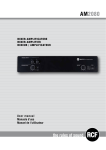
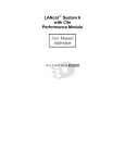
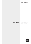
USER MANUAL
MANUALE D’USO
BM 3804
--DXT 3000 DESK-TOP
PAGING MICROPHONE
--BASE MICROFONICA DA
TAVOLO PER SISTEMA
DXT 3000
BE 3806
--ADDITIONAL KEYBOARD
FOR BM 3804 PAGING
MICROPHONES
--TASTIERA ADDIZIONALE
PER BASE MICROFONICA
BM 3804
TABLE OF CONTENTS
INDICE
ENGLISH
SAFETY PRECAUTIONS

DESCRIPTION
CONNECTION
4
6
7
BM 3804 – FRONT PANEL
11
BE 3806 ADDITIONAL KEYBOARD – FRONT PANEL
12
USE
14
SPECIFICATIONS
15
ITALIANO
AVVERTENZE PER LA SICUREZZA
16
DESCRIZIONE
18
COLLEGAMENTO
19
BM 3804 – PANNELLO FRONTALE
23
PULSANTIERA ADDIZIONALE BE 3806 – PANNELLO FRONTALE
24
UTILIZZO
26
DATI TECNICI
27
ENGLISH
SAFETY PRECAUTIONS
IMPORTANT NOTES
Before connecting and using this paging microphone, please read this instruction
manual carefully and keep it on hand for future reference. The manual is to
be considered an integral part of this product and must accompany it when
changing ownership as a reference for correct installation and use as well as
for the safety precautions. RCF S.p.A. will not assume any responsibility for the
incorrect installation and / or use of this product.
SAFETY PRECAUTIONS
NOTE: according to EN 54-16 standard, paging microphones shall be only
accessible by personnel having a specific responsibility for safety and who are
trained and authorized to operate in the following conditions: quiescent, voice
alarm, fault warning and disablement.
1. All the precautions, in particular the safety ones, must be read with special
attention, as they provide important information.
2. Make sure all connections have been made correctly before switching all
devices on.
Do not connect / disconnect paging microphones when the system is operating.
3. Protect paging microphone cables from damage and assure they are
positioned where these cannot be stepped on or crushed by objects.
4. Do not put the paging microphone into water (or another liquid), do not
throw it.
5. Never attempt to carry out any operations, modifications or repairs.
If the paging microphone does not work properly, contact your authorized service
centre.
6. Should the paging microphone emit any strange odour or even smoke, turn
the audio system off immediately and disconnect it.
7. RCF S.P.A. strongly recommends the sound system installation is only made
by professional qualified installers (or specialised firms), who can certify it
according to the regulations in force.
The entire audio system must comply with the current standards and regulations
regarding electrical systems.
8. Mechanical and electrical factors need to be considered when installing a
professional audio system (in addition to those which are strictly acoustic, such
as sound pressure, angles of coverage, frequency response, etc.).
9. Do not point the microphone at near loudspeakers, in order to avoid feedback.
4
IMPORTANT NOTES
ENGLISH
10. Hearing loss
Exposure to high sound levels can cause permanent hearing loss. The acoustic
pressure level that leads to hearing loss is different from person to person and
depends on the duration of exposure.
To prevent potentially dangerous exposure to high levels of acoustic pressure,
anyone who is exposed to these levels should use adequate protection devices.
When a transducer capable of producing high sound levels is being used, it is
necessary to wear ear plugs or protective earphones.
11. To prevent inductive effects from causing hum, noise and a bad system
operating, paging microphone cables should not be laid together with other
electric cables (mains) and loudspeaker lines.
12. Keep the paging microphone far from any excessive heat source.
13. Do not use solvents, alcohol, benzene or other volatile substances for
cleaning the external parts. Just use a dry cloth.
5
ENGLISH
RCF S.P.A. THANKS YOU FOR PURCHASING THIS PRODUCT, WHICH
HAS BEEN DESIGNED TO GUARANTEE RELIABILITY AND HIGH
PERFORMANCES.
DESCRIPTION
BM 3804 is a desktop paging microphone exclusively dedicated for the
RCF DXT 3000 system.
It can be directly connected to the MX 3250 main unit through a fourpair J-type fire-rated cable.
Up to four BM 3804 paging microphones (interlocked one another) can
be linked (daisy-chained) to the line.
BM 3804 front panel includes the following buttons:
-- Two for zone selection (first and second only)
-- PTT (‘Push To Talk’)
-- GEN CALL (general call)
-- CHIME (on / off)
-- EVAC message selection
-- ALERT message selection, this button also allows to mute the buzzer (when
a fault is detected)
-- A protected bistable emergency button (with red light) to start playing the
evacuation / alert message in all zones.
The system status is indicated by a LED bar.
Every BM 3804 paging microphones can be expanded with an additional
BE 3806 keyboard, which has six buttons for the six-zone selection of a
complete MX 3250 main unit (with three amplifier boards).
The first BM 3804 paging microphone (of the line) is directly powered by
the MX 3250 main unit, while the second, the third and the fourth need
24 V dc adapters (500 mA, i.e. RCF AC AD 2405, optional).
Other features:
-- Casing in die-cast metal
-- Preamplified cardioid hi-quality microphone, with flexible 445 mm long
-- Comprehensive self-diagnostics (EN 54-16)
-- Connection cable included (5 m, with RJ 45).
6
ENGLISH
CONNECTION
BM 3804 – REAR PANEL
INPUT
POWER SUPPLY
INPUT
OUTPUT
INPUT : RJ 45 port to be linked to either the MX 3250 main unit
PAGING IN or the previous BM 3804 paging microphone OUTPUT.
OUTPUT : RJ 45 port to be linked to the next BM 3804 paging
microphone INPUT. PIN
1
2
3
4
5
6
7
8
INPUT
Audio signal (+, hot)
Audio signal (–, cold)
Power supply
Ground
Ground
Ground
RS 485 A (+)
RS 485 B (–)
RJ 45 SOCKET
PIN
1
2
3
4
5
6
7
8
OUTPUT
Audio signal (+, hot)
Audio signal (–, cold)
(not used)
Ground
Ground
(not used)
RS 485 A (+)
RS 485 B (–)
8642
7531
RJ 45 PLUG
|1|2|3|4|5|6|7|8|
7
ENGLISH
RS 485
B
A
GROUND
G
POWER SUPPLY
AUDIO SIGNAL
+V
–
+
Brown
Brown/White
Green
Blue/White
Blue
Green/White
Orange
Orange/White
Brown
Brown/White
Green
Blue/White
Blue
Green/White
Orange
Orange/White
12345678
CABLE TO LINK THE FIRST BM 3804 PAGING MIC. TO THE MX 3250
MAIN UNIT
RJ
POWER SUPPLY INPUT: input for the external 24 V dc adapter (500 mA,
i.e. optional RCF AC AD 2405), not included; remove the cable guide by
unscrewing its screw.
Notes:
-- The first BM 3804 paging microphone is directly powered by the MX 3250 main
unit (the external AC AD2405 adapter is not necessary).
-- The second, the third and the fourth BM 3804 all need an AC AD2405 adapter
(not included).
BM 3804 – INTERNAL DIP-SWITCH SETTINGS
WARNING: the internal dip-switch setting shall be carried out only by either
RCF or an authorised service centre.
NOTE: any setting change shall be carried out when the system is switched off
(or the paging microphone is disconnected).
On the BM 3804 rear side, remove the central blank panel to access the six
dip-switches.
8
DIP-SWITCH
1
2
3
FUNCTION
ID (0)
ID (1)
ID (2)
4
EMERGENCY
5
6
TEST
---
NOTES
Digital address setting (see the next table).
Digital address setting (see the next table).
Not used; leave it OFF.
If set to ON, the paging microphone can be used to start playing either the
evacuation (EVAC button 13 ) or the alert message (ALERT button 7 ).
If set to OFF, emergency functions are disabled.
Service / maintenance function: leave it OFF.
Not used; leave it OFF.
DIP 2
off
off
ON
ON
DIGITAL ADDRESS
0
1
2
3
ENGLISH
DIP 1
off
ON
off
ON
NOTES
First BM 3804
Second BM 3804
Third BM 3804
Fourth BM 3804
NOTE: after setting digital addresses properly and rebooting the system, it will be
MX 3250 main unit) the DISCOVERY function (automatic
detection of all paging microphones linked to the system).
necessary to select (in the
BE 3806 ADDITIONAL KEYBOARDS
Every BM 3804 paging microphone can be expanded with a BE 3806
additional keyboard having six buttons, which can be used to select each
single zone (1 to 6, if available).
Notes:
-- The first BM 3804 paging microphone is directly powered by the MX
3250 main unit (the external AC AD2405 adapter is not necessary).
-- The second, the third and the fourth BM 3804 all need an AC AD2405
adapter (not included).
Looking at the rear side, remove both the BE 3806 right blank
panel and the BM 3804 left blank panel.
Link the BE 3806 additional keyboard to the BM 3804 paging
microphone through its flat-cable connected to the two rear ports.
Pay attention to the flat cable right way, indicated by its red
wire (see the next figure).
BE
3806
BM
3804
4
RED
BM 3804
BE 3806
9
ENGLISH
Fix the BE 3806 additional keyboard to the BM
3804 paging microphone by using the dedicated
plate (included in the BE 3806 package) and
four screws.
BM
3804
BE
3806
BLOCK DIAGRAM
MX 3250
BM380x IN
OUT
IN
4
4
4
AC AD2405
IN
3
AC AD2405
BM 3804
BE 3806
IN
OUT
IN
4
2
4
1
AC AD2405
BM 3804
BE 3806
Up to four BM 3804 paging microphones (with or without BE 3806
additional keyboards) can be linked (daisy-chained) to the line connected to
the BM380X input of the MX 3250 unit.
BM 3804 paging microphones are interlocked one another.
The second, the third and the fourth BM 3804 all need an AC AD2405
adapter (not included).
10
OUT
BM 3804
BE 3806
BM 3804
BE 3806
ENGLISH
BM 3804 – FRONT PANEL
1 CHIME button: push to toggle on/off the chime
(sent before an announcement).
2 CHIME LED (green): when lit, the chime
(sent before an announcement) is enabled.
Push its respective button 1 to toggle on/off.
3 PTT (‘Push To Talk’) button: push and hold down to turn
the microphone on and page the zones previously selected.
16
17
18
15
19
20
21
14
13
4 PTT LED (green): when lit, the microphone is turned on
(by pushing the PTT button 3 ).
5 GEN CALL (general call) button: push to select all zones
BM
EVAC
8b 10a 10b 12a
8a
ALERT / SILENCE
ZONE A
ZONE B
7
9
11
(push again to cancel).
12b
6 GEN CALL LED (green): when lit, it indicates the
general call selection (by pushing the GEN CALL button 5 ).
7 ALERT / SILENCE button
2
CHIME
1
4
PTT
3
6
GEN
CALL
5
ALERT function: push to select (push again to cancel) the
alert message, which will be sent to all zones as soon as the
emergency button 15 is pressed. When the alert message
playback is in progress, the ALERT / SILENCE button
(if pushed once) allows to mute it (but without stopping it), then push it
again to unmute.
The evacuation message (selectable by the EVAC button 13 ) has priority over the
alert message.
SILENCE function: when a fault has been detected, push it to mute the
buzzer.
8a ALERT LED (green): when lit, it indicates the alert message selection, but
not its playback.
8b SILENCE LED (white): it flashes when a fault is detected.
9 ZONE A button: push to select the system first zone (push again to
cancel).
10a ZONE A LED (green): when lit, it indicates the selection of the first zone.
10b ZONE A LED (yellow / red):
-- When lit yellow, the first zone is busy
-- When lit red, the evacuation / alert message is currently sent to the first zone.
11
ENGLISH
11 ZONE B button: push to select the system second zone (push again to
cancel).
12a ZONE B LED (green): when lit, it indicates the selection of the second
zone.
12b ZONE B LED (yellow / red):
-- When lit yellow, the second zone is busy
-- When lit red, the evacuation / alert message is currently sent to the second zone.
13 EVAC button: push to select (push again to cancel) the evacuation message,
which will be sent to all zones as soon as the emergency button 15 is pressed.
The evacuation message has priority over the alert message.
14 LED EVAC (red): when lit, it indicates the evacuation message selection,
but not its playback.
15 Protected bistable emergency button (with red light) that is working
only in paging microphones having the emergency function enabled.
If pressed, after a few seconds, the evacuation / alert message playback starts
(choose first the message by pushing either the EVAC 13 or the ALERT 7
button).
Push it again to release it and stop playing the evacuation / alert message.
16 ÷ 21 LEDs
No.
SILK SCREEN
COLOUR
16
POWER
green
The paging microphone is properly powered and operating.
INDICATION (WHEN LIT)
17
L/FLT
yellow
Detected fault in the paging microphone.
18
G/FLT
yellow
One or more faults are detected in the system.
19
EVAC
red
Evacuation message playback is in progress.
20
ALERT
red
Alert message playback is in progress.
21
BUSY
yellow
The line is engaged.
BE 3806 ADDITIONAL KEYBOARD – FRONT PANEL
22 A button: push to select the system first zone (push again to cancel).
This button is equivalent to the BM 3804 ZONE A button 9 .
23a A LED (green): when lit, it indicates the selection of the first zone.
23b A LED (yellow / red): when is lit yellow, the first zone is busy; when is lit
red, the evacuation / alert message is currently sent to the first zone.
12
23a
A
22
25a B LED (green): when lit, it indicates the selection of the second zone.
23b
25b B LED (yellow / red): when is lit yellow, the second zone is busy;
25a
when is lit red, the evacuation / alert message is currently sent to the
second zone.
B
(push again to cancel).
27a
C
zone.
27b C LED (yellow / red): when is lit yellow, the third zone is busy;
when is lit red, the evacuation / alert message is currently sent to the
third zone.
zone.
29a
D
28
29b
31a
E
30
31b
29b D LED (yellow / red): when is lit yellow, the fourth zone is busy;
when is lit red, the evacuation / alert message is currently sent to the
fourth zone.
26
27b
28 D button: push to select the system fourth zone
(push again to cancel).
29a D LED (green): when lit, it indicates the selection of the fourth
24
25b
26 C button: push to select the system third zone
27a C LED (green): when lit, it indicates the selection of the third
ENGLISH
24 B button: push to select the system second zone
(push again to cancel).
This button is equivalent to the BM 3804 ZONE B button 11 .
33a
F
30 E button: push to select the system fifth zone
(push again to cancel).
32
33b
31a E LED (green): when lit, it indicates the selection of the fifth zone.
31b E LED (yellow / red): when is lit yellow, the fifth zone is busy; when is lit
red, the evacuation / alert message is currently sent to the fifth zone.
32 F button: push to select the system sixth zone (push again to cancel).
33a F LED (green): when lit, it indicates the selection of the sixth zone.
33b F LED (yellow / red): when is lit yellow, the sixth zone is busy; when is lit
red, the evacuation / alert message is currently sent to the sixth zone.
13
ENGLISH
USE
Before using the paging microphone, choose to enable / disable the chime by
pushing the CHIME button 1 .
SELECTIVE OR GENERAL CALLS
1. Make sure the line has not been already engaged (zone LEDs lit yellow or
red 10b 12b 23b 25b 27b 29b 31b 33b ).
2. Select one or more zones by pushing their respective buttons of either
the BM 3804 paging microphone 9 11 or the BE 3806 keyboard (if
present) 22 24 26 28 30 32 .
The corresponding LEDs 10a 12a / 23a 25a 27a 29a 31a 33a turn
green.
A further press of a button unchecks its respective zone.
Push the GEN CALL button 5 (instead) to make a general call (the
corresponding LED 6 lights up).
3. Press and hold the PTT button 3 to turn the microphone on (the PTT LED
4 lights up).
4. After the end of the announcement, release the PTT button PTT 3 .
EVACUATION / ALERT MESSAGE PLAYBACK
The emergency function of the BM 3804 paging microphone must be enabled
(internal dip-switch no.4 set to ON).
1. Select either the evacuation (by pushing the EVAC button 13 ) or the alert
message (ALERT button 7 ).
2. Lift the guard and push the emergency red button 15 , after a few seconds
the selected message playback starts (all zone LEDs are lit red 10b 12b
23b 25b 27b 29b 31b 33b ).
3. Push the emergency red button 15 again to stop playing the evacuation
/ alert message.
The delay (a few seconds) of the evacuation / alert message playback is a precaution
that allows you to immediately remedy any accidental activation, by pressing the
emergency button again.
14
ENGLISH
SPECIFICATIONS
BM 3804
Microphone type:
electret
Polar patter:
cardioid
Output impedance:
Microphone sensitivity:
Frequency response:
Power supply:
Dimensions:
Gooseneck length:
Net weight:
470 Ω (1 kHz)
– 65 dB ± 3 dB (0 dB=1V/μbar, 1 kHz)
50 Hz ÷ 18 kHz (– 3 dB)
12 V dc (MX 3250), 24 V c.c.
(external adapter, RCF AC AD2405)
128 x 39 x 203 mm (without gooseneck)
445.5 mm
1.2 kg (2.7 lbs)
BE 3806
Power supply:
though the BM 3804 paging microphone
Dimensions:
78 mm x 39 mm x 203 mm
Net weight:
0.7 kg (1.6 lbs) 15
ITALIANO
AVVERTENZE PER LA SICUREZZA
IMPORTANTE
Prima di collegare ed utilizzare la base microfonica, leggere attentamente le
istruzioni contenute in questo manuale, il quale è da conservare per riferimenti
futuri. Il presente manuale costituisce parte integrante del prodotto e deve
accompagnare quest’ultimo anche nei passaggi di proprietà, per permettere
al nuovo proprietario di conoscere le modalità d’installazione e d’utilizzo e le
avvertenze per la sicurezza.
L’installazione e l’utilizzo errati del prodotto esimono RCF S.p.A. da ogni
responsabilità.
AVVERTENZE PER LA SICUREZZA
NOTA: secondo la norma EN 54-16, i microfoni per annunci d’emergenza
devono essere accessibili solo da persone che hanno responsabilita in materia di
sicurezza e sono formate ed autorizzate ad operare nelle condizioni di inattivita,
allarme vocale, avviso di guasto e disabilitazione.
1. Tutte le avvertenze, in particolare quelle relative alla sicurezza, devono essere
lette con particolare attenzione, in quanto contengono importanti informazioni.
2. Prima di accendere le apparecchiature, assicurarsi che tutte le connessioni
siano corrette.
Non collegare / scollegare la base microfonica quando il sistema è acceso.
3. Accertarsi che il cavo della base microfonica non possa essere calpestato o
schiacciato da oggetti, al fine di salvaguardarne l’integrità.
4. Non immergere la base microfonica nell’acqua (od in altri liquidi), non
lanciarla o lasciarla cadere.
5. Non eseguire sulla base microfonica interventi / modifiche / riparazioni;
contattare i centri di assistenza autorizzati nel caso che non funzioni
correttamente.
6. Nel caso che dalla base microfonica provengano stranamente odori anomali
od addirittura fumo, spegnere immediatamente il sistema audio e scollegarla.
7. RCF S.p.A. raccomanda vivamente che l’installazione del sistema audio
sia eseguita solamente da installatori professionali qualificati (oppure da ditte
specializzate) in grado di farla correttamente e certificarla in accordo con le
normative vigenti. Tutto il sistema audio dovrà essere in conformità con le norme
e le leggi vigenti in materia di impianti elettrici.
8. I fattori meccanici ed elettrici sono da considerare quando si installa un
sistema audio professionale (oltre a quelli prettamente acustici, come la
pressione sonora, gli angoli di copertura, la risposta in frequenza, ecc.).
9. Non puntare la base microfonica verso un diffusore acustico vicino, onde
evitare un possibile innesco.
16
IMPORTANTE
ITALIANO
10. Perdita dell’udito
L’esposizione ad elevati livelli sonori può provocare la perdita permanente
dell’udito. Il livello di pressione acustica pericolosa per l’udito varia sensibilmente
da persona a persona e dipende dalla durata dell’esposizione. Per evitare
un’esposizione potenzialmente pericolosa ad elevati livelli di pressione acustica,
è necessario che chiunque sia sottoposto a tali livelli utilizzi delle adeguate
protezioni; quando si fa funzionare un trasduttore in grado di produrre elevati
livelli sonori, è necessario indossare dei tappi per orecchie o delle cuffie protettive.
11. Per evitare che fenomeni induttivi diano luogo a ronzii, disturbi e
compromettano il buon funzionamento dell’impianto, il cavo della base
microfonica non deve essere canalizzato insieme ai conduttori dell’energia
elettrica e/o alle linee dei diffusori acustici.
12. Collocare la base microfonica lontano da fiamme (o fonti di calore eccessivo).
13. Non usare solventi, alcool, benzina o altre sostanze volatili per la pulitura
delle parti esterne, ma un panno asciutto.
17
ITALIANO
RCF S.P.A. VI RINGRAZIA PER L’ACQUISTO DI QUESTO PRODOTTO,
REALIZZATO IN MODO DA GARANTIRNE L’AFFIDABILITÀ E
PRESTAZIONI ELEVATE.
DESCRIZIONE
BM 3804 è una base microfonica, esclusivamente dedicata per il sistema
RCF DXT 3000, che può essere collegata direttamente ad un’unità
centrale MX 3250 tramite un cavo antifiamma di tipo “J” (quattro coppie
di conduttori); è possibile collegare in cascata (nella stessa linea) fino a
quattro basi microfoniche BM 3804 (interbloccate tra loro).
Il suo pannello frontale include i seguenti tasti:
-- due per la selezione delle prime due zone;
-- uno per l’attivazione del microfono (PTT, “Push To Talk”, “premere per
parlare”);
-- uno per la chiamata generale (GEN CALL);
-- uno per l’abilitazione (o meno) del tono di preavviso prima di un annuncio
(CHIME);
-- uno per la selezione del messaggio d’evacuazione;
-- uno per la selezione del messaggio d’allerta, tasto che permette inoltre di
silenziare il cicalino in caso di segnalazione di un guasto;
-- un tasto protetto bistabile (con luce rossa) d’emergenza, per invio del
messaggio d’evacuazione o d’allerta in tutte le zone.
Sono presenti inoltre degli indicatori luminosi (LED) per lo stato del
sistema.
Ogni base microfonica BM 3804 può essere espansa con una pulsantiera
aggiuntiva BE 3806, la quale ha sei tasti per la selezione di tutte
le sei zone di un’unità centrale MX 3250 completa (con tre schede
amplificatore).
La prima base microfonica BM 3804 della linea è alimentata direttamente
dall’unità centrale MX 3250, mentre la seconda, la terza e la quarta
necessitano di alimentatori esterni 24 V c.c. (500 mA, ad esempio,
l’opzionale RCF AC AD 2405).
Altre caratteristiche:
-- involucro in metallo pressofuso;
-- microfono cardioide preamplificato di alta qualità, con flessibile di
lunghezza 445 mm;
-- autodiagnosi completa (EN 54-16);
-- cavo di collegamento incluso (5 m, con connettori RJ 45).
18
ITALIANO
COLLEGAMENTO
BM 3804 – PANNELLO POSTERIORE
INPUT
POWER SUPPLY
INPUT
OUTPUT
INPUT (ingresso): presa RJ 45 per il collegamento di una porta
PAGING IN dell'unità centrale MX 3250 oppure alla presa OUTPUT
della base microfonica precedente.
OUTPUT (uscita): presa RJ 45 per il collegamento alla porta INPUT
della base microfonica successiva. PIN
1
2
3
4
5
6
7
8
INPUT
Segnale audio (+)
Segnale audio (–)
Alimentazione
Massa
Massa
Massa
RS 485 A (+)
RS 485 B (–)
PRESA RJ 45
PIN
1
2
3
4
5
6
7
8
OUTPUT
Segnale audio (+)
Segnale audio (–)
(non usato)
Massa
Massa
(non usato)
RS 485 A (+)
RS 485 B (–)
8642
7531
CONNETTORE RJ 45
|1|2|3|4|5|6|7|8|
19
ITALIANO
RS 485
B
A
MASSA
G
ALIMENTAZIONE
SEGNALE AUDIO
+V
–
+
Marrone
Biancomarrone
Verde
Biancoblù
Blu
Biancoverde
Arancio
Biancoarancio
Marrone
Biancomarrone
Verde
Biancoblù
Blu
Biancoverde
Arancio
Biancoarancio
12345678
CAVO PER IL COLLEGAMENTO DELLA PRIMA BASE MICROFONICA
BM 3804 ALL'UNITÀ CENTRALE MX 3250
RJ
POWER SUPPLY INPUT: ingresso per l'alimentatore esterno 24 V c.c.
non incluso (min. 250 mA, es. RCF AC AD 2405 opzionale); rimuovere il
passacavo svitando la sua vite.
Note:
-- la prima base microfonica BM 3804 è direttamente alimentata dall'unità centrale
MX 3250 (l'alimentatore AC AD2405 non è necessario);
-- la seconda, la terza e la quarta base microfonica BM 3804 necessitano, ciascuna,
di un alimentatore AC AD2405 (non incluso).
BM 3804 – IMPOSTAZIONE DEI MICROINTERRUTTORI INTERNI
ATTENZIONE: l’impostazione del microinterruttori interni (dip-switch) deve
essere effettuata direttamente da RCF oppure solo da un centro d’assistenza
autorizzato.
NOTA: qualsiasi modifica alle impostazioni deve essere effettuata con il sistema
spento (o con la base microfonica scollegata).
Sul retro della base microfonica BM 3804, rimuovere il pannello cieco
centrale per accedere ai sei microinterruttori (dip-switch).
20
DIP-SWITCH
1
2
3
FUNZIONE
INDIRIZZO DIGITALE (0)
INDIRIZZO DIGITALE (1)
INDIRIZZO DIGITALE (2)
4
EMERGENZA
5
6
TEST
---
NOTE
Impostazione indirizzo digitale (vedere la tabella successiva).
Impostazione indirizzo digitale (vedere la tabella successiva).
Non utilizzato; lasciare su OFF.
Se impostato su ON, è possibile utilizzare la base microfonica per
l’invio dei messaggi d’evacuazione (tasto EVAC 13 ) o d’allerta
(tasto ALERT 7 );
se impostato su OFF, le funzioni d’emergenza sono disabilitate.
Funzione di servizio / manutenzione; lasciare su OFF.
Non utilizzato; lasciare su OFF.
DIP 2
off
off
ON
ON
INDIRIZZO DIGITALE
0
1
2
3
ITALIANO
DIP 1
off
ON
off
ON
NOTE
Prima base microfonica BM 3804
Seconda base microfonica BM 3804
Terza base microfonica BM 3804
Quarta base microfonica BM 3804
NOTA: dopo aver impostato l'indirizzo digitale corretto di ciascuna base
BM 3804 e riavviato il sistema, occorre selezionare (tramite il
menù dell'unità centrale MX 3250) la funzione DISCOVERY (riconoscimento
automatico di tutte le basi microfoniche collegate al sistema).
microfonica
PULSANTIERE ADDIZIONALI BE 3806
Ogni base microfonica BM 3804 può essere espansa con una pulsantiera
addizionale BE 3806 avente sei tasti, i quali si usano per la selezione di
ciascuna singola zona (da 1 a 6, se disponibili).
NOTE:
-- la prima base microfonica BM 3804 è direttamente alimentata dall'unità
centrale MX 3250 (l'alimentatore AC AD2405 non è necessario);
-- la seconda, la terza e la quarta base microfonica BM 3804 necessitano,
ciascuna, di un alimentatore AC AD2405 (non incluso).
Rimuovere il pannello cieco destro (guardando il retro) della
pulsantiera addizionale BE 3806 ed il pannello cieco sinistro
della base microfonica BM 3804.
Collegare la pulsantiera addizionale BE 3806 alla base
microfonica BM 3804 tramite il cavetto dedicato (“flat cable”)
da fissare alle porte posteriori; prestare attenzione al verso
corretto indicato dal filo rosso (vedere la figura successiva).
BE
3806
BM
3804
4
ROSSO
BM 3804
BE 3806
21
ITALIANO
Fissare la pulsantiera addizionale BE 3806 alla
base microfonica BM 3804 usando l'apposita
piastrina (inclusa nell'imballo della pulsantiera
BE 3806) e quattro viti.
BM
3804
BE
3806
SCHEMA A BLOCCHI
MX 3250
BM380x IN
OUT
IN
4
4
4
AC AD2405
IN
3
AC AD2405
BM 3804
BE 3806
OUT
IN
OUT
IN
4
2
4
1
AC AD2405
BM 3804
BE 3806
Si possono collegare (in cascata e condividendo la stessa linea) fino a quattro
basi microfoniche BM 3804 (con o senza pulsantiere addizionali BE 3806)
all'ingresso BM380x dell'unità centrale MX 3250; le basi microfoniche BM
3804 sono interbloccate tra loro.
La seconda, la terza e la quarta base microfonica BM 3804 necessitano,
ciascuna, di un alimentatore 24 V c.c. – 500 mA (non incluso, es. RCF AC
AD2405).
22
BM 3804
BE 3806
BM 3804
BE 3806
ITALIANO
BM 3804 – PANNELLO FRONTALE
1 Tasto CHIME: premere per abilitare o disabilitare
il tono di preavviso (“chime”) prima di un annuncio
microfonico.
16
17
2 LED CHIME (verde): se acceso, il tono di preavviso
(prima di un annuncio microfonico) è abilitato tramite il
rispettivo tasto 1 .
18
3 Tasto PTT (“Push To Talk”): premere e tener premuto
per attivare il microfono nelle zone selezionate in
precedenza.
21
15
19
20
4 LED PTT (verde): se acceso, il microfono è stato attivato
tramite il rispettivo tasto 3 .
14
13
BM
EVAC
8b 10a 10b 12a
8a
ALERT / SILENCE
ZONE A
ZONE B
7
9
11
12b
5 Tasto GEN CALL (chiamata generale): premere per
selezionare tutte le zone disponibili (premere di nuovo per
cancellare la selezione).
6 LED GEN CALL (verde): se acceso, indica la selezione in
corso della chiamata generale tramite il rispettivo tasto 5 .
2
CHIME
1
4
PTT
3
6
GEN
CALL
5
7 Tasto ALERT / SILENCE
Funzione ALERT: premere per selezionare (una seconda
pressione cancella la selezione) il messaggio d’allerta,
il quale sarà inviato in tutte le zone non appena sarà premuto il tasto
d’emergenza 15 . Durante la riproduzione del messaggio d’allerta,
il tasto ALERT / SILENCE, se premuto una volta, permette di porre
momentaneamente a zero il volume del messaggio (il quale non è fermato);
una seconda pressione dl tasto ripristina il livello impostato.
Il messaggio d’evacuazione (selezionabile tramite il tasto EVAC 13 ) è prioritario su
quello d’allerta.
Funzione SILENCE: quando è in corso una segnalazione di guasto, premere
per silenziare il cicalino.
8a LED ALERT (verde): se acceso, indica la selezione del messaggio d’allerta,
ma non la sua riproduzione.
8b LED SILENCE (bianco): lampeggia quando è in corso una segnalazione di
guasto.
9 Tasto ZONE A: premere per selezionare la prima zona del sistema (premere
di nuovo per cancellare la selezione).
10a LED ZONE A (verde): quando acceso, indica la selezione della prima zona.
23
ITALIANO
10b LED ZONE A (giallo / rosso):
quando è acceso giallo, la prima zona è occupata;
quando è acceso rosso, è in corso il messaggio d’evacuazione o d’allerta
nella prima zona.
11 Tasto ZONE B: premere per selezionare la seconda zona del sistema
(premere di nuovo per cancellare la selezione).
12a LED ZONE B (verde): quando acceso, indica la selezione della seconda
zona.
12b LED ZONE B (giallo / rosso):
-- quando è acceso giallo, la seconda zona è occupata;
-- quando è acceso rosso, è in corso il messaggio d'evacuazione o d'allerta
nella seconda zona.
13 Tasto EVAC: premere per selezionare (una seconda pressione cancella
la selezione) il messaggio d'evacuazione, il quale sarà inviato in tutte le zone
non appena sarà premuto il tasto d'emergenza 15 .
Il messaggio d'evacuazione è prioritario su quello d'allerta.
14 LED EVAC (rosso): se acceso, indica la selezione del messaggio
d'evacuazione, ma non la sua riproduzione.
15 Tasto protetto bistabile d'emergenza con luce rossa (si può attivare solo
nelle basi microfoniche con funzione d'emergenza): se premuto, dopo alcuni
secondi si attiva il messaggio d'evacuazione o d'allerta selezionato tramite
i tasti EVAC 13 oppure ALERT 7 ; premerlo di nuovo per rilasciarlo e
fermare il messaggio in corso.
16 ÷ 21 LED (INDICATORI LUMINOSI)
Nr.
SERIGRAFIA
COLORE
16
POWER
verde
La base microfonica è alimentata correttamente e funzionante.
INDICAZIONE (CON LED ACCESO)
17
L/FLT
giallo
Guasto rilevato nella base microfonica.
18
G/FLT
giallo
Uno o più guasti sono presenti nel sistema.
19
EVAC
rosso
Messaggio d’evacuazione in corso.
20
ALERT
rosso
Messaggio d’allerta in corso.
21
BUSY
giallo
La linea è occupata.
PULSANTIERA ADDIZIONALE BE 3806 – PANNELLO FRONTALE
22 Tasto A: premere per selezionare la prima zona del sistema (premere di
nuovo per cancellare la selezione).
Questo tasto è equivalente al ZONE A 9 della BM 3804.
23a LED A (verde): quando acceso, indica la selezione della prima zona.
24
23a
A
25b LED B (giallo / rosso): quando è acceso giallo, la seconda
zona è occupata; quando è acceso rosso, è in corso il messaggio
d'evacuazione o d'allerta nella seconda zona.
25a
B
27a
C
29a
D
28
29b
31a
E
30
31b
29a LED D (verde): quando acceso, indica la selezione della quarta
zona.
29b LED D (giallo / rosso): quando è acceso giallo, la quarta
zona è occupata; quando è acceso rosso, è in corso il messaggio
d’evacuazione o d’allerta nella quarta zona.
26
27b
27b LED C (giallo / rosso): quando è acceso giallo, la terza
zona è occupata; quando è acceso rosso, è in corso il messaggio
d'evacuazione o d'allerta nella terza zona.
28 Tasto D: premere per selezionare la quarta zona del sistema
(premere di nuovo per cancellare la selezione).
24
25b
26 Tasto C: premere per selezionare la terza zona del sistema
(premere di nuovo per cancellare la selezione).
27a LED C (verde): quando acceso, indica la selezione della terza
zona.
22
23b
24 Tasto B: premere per selezionare la seconda zona del sistema
(premere di nuovo per cancellare la selezione).
Questo tasto è equivalente al ZONE B 11 della BM 3804.
25a LED B (verde): quando acceso, indica la selezione della seconda
zona.
ITALIANO
23b LED A (giallo / rosso): quando è acceso giallo, la prima
zona è occupata; quando è acceso rosso, è in corso il messaggio
d'evacuazione o d'allerta nella prima zona.
33a
F
32
33b
30 Tasto E: premere per selezionare la quinta zona del sistema
(premere di nuovo per cancellare la selezione).
31a LED E (verde): quando acceso, indica la selezione della quinta zona.
31b LED E (giallo / rosso): quando è acceso giallo, la quinta zona è
occupata; quando è acceso rosso, è in corso il messaggio d’evacuazione o
d’allerta nella quinta zona.
32 Tasto F: premere per selezionare la sesta zona del sistema (premere di
nuovo per cancellare la selezione).
33a LED F (verde): quando acceso, indica la selezione della sesta zona.
33b LED F (giallo / rosso): quando è acceso giallo, la sesta zona è occupata;
quando è acceso rosso, è in corso il messaggio d’evacuazione o d’allerta nella
sesta zona.
25
ITALIANO
UTILIZZO
Prima di utilizzare la base microfonica, scegliere inoltre se attivare (o meno) il
tono di preavviso premendo il tasto CHIME 1 .
CHIAMATA SELETTIVA O GENERALE
1. Assicurarsi che la linea non sia già occupata (LED di zona accesi gialli o
rossi 10b 12b 23b 25b 27b 29b 31b 33b ).
2. Selezionare una o più zone premendo i rispettivi tasti della base microfonica
BM 3804 9
11 oppure della pulsantiera BE 3806 (se presente) 22 24
26 28 30 32 ; si accendono i corrispondenti LED verdi 10a 12a / 23a
25a 27a 29a 31a 33a . Una successiva pressione di un tasto, deseleziona la
rispettiva zona. Per effettuare una chiamata generale su tutte le zone, premere
invece il tasto GEN CALL 5 (il rispettivo LED 6 si illumina).
3. Premere e tener premuto il tasto PTT 3 per effettuare l'annuncio
microfonico (il LED PTT 4 si accende).
4. Al termine dell'annuncio microfonico, rilasciare il tasto PTT 3 .
RIPRODUZIONE DEL MESSAGGIO D'EVACUAZIONE O D'ALLERTA
Deve essere abilitata la funzione d'emergenza della base microfonica BM 3804
utilizzata (microinterruttore nr.4 interno impostato su ON).
1. Selezionare il messaggio d'evacuazione (premendo il tasto EVAC 13 )
oppure quello d'allerta (tasto ALERT 7 ).
2. Sollevare la protezione e premere il tasto rosso d'emergenza 15 , dopo
pochi secondi inizia la riproduzione del messaggio selezionato (tutti i LED
di zona sono accesi rossi 10b 12b 23b 25b 27b 29b 31b 33b ).
3. Premere di nuovo il tasto rosso d'emergenza 15 per fermare il messaggio.
Il ritardo di qualche secondo della riproduzione del messaggio d'evacuazione o
d'allerta è una precauzione che permette di rimediare immediatamente ad un'eventuale
attivazione accidentale (premendo di nuovo il tasto rosso d'emergenza).
26
ITALIANO
DATI TECNICI
BM 3804
Tipo microfono:
elettrete
Direttività:
cardioide
Impedenza d’uscita:
470 Ω (1 kHz)
Sensibilità microfono:
– 65 dB ± 3 dB (0 dB=1V/μbar, 1 kHz)
Risposta in frequenza:
50 Hz ÷ 18 kHz (– 3 dB)
Alimentazione:
Dimensioni:
Lunghezza flessibile:
Peso netto:
12 V c.c. (MX 3250),
24 V c.c.
(alimentatore esterno RCF AC AD2405)
128 x 39 x 203 mm (senza flessibile)
445,5 mm
1,2 kg
BE 3806
Alimentazione:
tramite base microfonica BM 3804
Dimensioni:
78 mm x 39 mm x 203 mm
Peso netto:
0,7 kg 27
Except possible errors and omissions.
RCF S.p.A. reserves the right to make modifications without prior notice.
Salvo eventuali errori ed omissioni.
RCF S.p.A. si riserva il diritto di apportare modifiche senza preavviso.
HEADQUARTERS:
RCF S.p.A. Italy
tel. +39 0522 274 411
e-mail: [email protected]
RCF UK
tel. 0844 745 1234
Int. +44 870 626 3142
e-mail: [email protected]
RCF France
tel. +33 1 49 01 02 31
e-mail: [email protected]
RCF Germany
tel. +49 2203 925370
e-mail: [email protected]
RCF Spain
tel. +34 91 817 42 66
e-mail: [email protected]
RCF USA Inc.
tel. +1 (603) 926-4604
e-mail: [email protected]
2014 / 11
www.rcfaudio.com
10307470 revA
RCF Belgium
tel. +32 (0) 3 - 3268104
e-mail: [email protected]