1
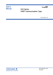
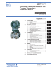
User’s
Manual
Model EJA Series
HART Protocol
IM 01C22T01-01E
IM 01C22T01-01E
Yokogawa Electric Corporation
8th Edition
CONTENTS
CONTENTS
PRELIMINARY ........................................................................................................ ii
1.
ZERO POINT ADJUSTMENT ....................................................................... 1-1
1.1
Zero Point Adjustment ........................................................................ 1-1
1.1.1 Using the HART Communicator ................................................... 1-2
1.1.2 Using the Transmitter Zero-adjustment Screw ............................ 1-2
1.2 Auto LRV (Change Low Range Value) ............................................... 1-3
1.2.1 Using Model 275 — Apply Values ............................................... 1-3
1.2.2 Setting the Range Using the Range-setting Switch .................... 1-3
2.
HART COMMUNICATOR OPERATION ....................................................... 2-1
2.1
Conditions of Communication Line ..................................................... 2-1
2.1.1 Interconnection Between DPharp and HART Communicator ...... 2-1
2.1.2 Communication Line Requirements ............................................. 2-1
2.2 Basic Operation of the HART Communicator (Model 275) ................ 2-2
2.2.1 Keys and Functions ...................................................................... 2-2
2.2.2 Display .......................................................................................... 2-3
2.2.3 Calling Up Menu Addresses ........................................................ 2-3
2.2.4 Entering, Setting, and Sending Data ........................................... 2-4
2.3 Parameters .......................................................................................... 2-5
2.3.1 Parameter Usage and Selection .................................................. 2-5
2.3.2 Menu Tree .................................................................................... 2-6
2.3.3 Setting Parameters ....................................................................... 2-7
(1) Tag No. ........................................................................................ 2-7
(2) Unit .............................................................................................. 2-7
(3) Range Change ............................................................................ 2-7
(4) Output Mode (Linear/Sq root) ..................................................... 2-8
(5) Damping Time Constants ............................................................ 2-9
(6) Output Signal Low Cut Mode Setup ............................................ 2-9
(7) Bi-directional Flow Measurement .............................................. 2-10
(8) Change Output Limits ............................................................... 2-10
(9) Integral Indicator Display Mode ................................................. 2-10
(10) Integral Indicator Scale ............................................................. 2-10
(11) Unit for Displayed Temperature ................................................. 2-12
(12) Unit for Displayed Static Pressure ............................................ 2-12
(13) Test Output ................................................................................ 2-13
(14) Sensor Trim ............................................................................... 2-13
(15) Trim Analog Output ................................................................... 2-14
(16) Burst Mode ................................................................................ 2-16
(17) Multidrop Mode ......................................................................... 2-17
(18) External Switch Mode ............................................................... 2-17
(19) Software Write Protect .............................................................. 2-18
(20) Hardware Write Protect and Burnout Direction
(with Optional code /F1) ............................................................ 2-19
(21) H2O Unit Select ......................................................................... 2-19
2.4 Self-Diagnostics ................................................................................ 2-20
2.4.1 Checking for Problems ............................................................... 2-20
(1) Identify Problems with HART Communicator ............................ 2-20
(2) Checking with Integral Indicator ................................................ 2-21
3.
PARAMETER LISTS ..................................................................................... 3-1
REVISION RECORD
FD No. IM 01C22T01-01E
8th Edition: Oct. 2008(YK)
All Rights Reserved, Copyright © 1995, Yokogawa Electric Corporation
i
IM 01C22T01-01E
PRELIMINARY
PRELIMINARY
This manual describes the function, performance, and
operating procedures of the DPharp EJA Series with
HART protocol. The DPharp EJA Series with HART
protocol uses the same pressure sensing element as in
DPharp EJA with BRAIN protocol. Therefore, this
manual describes only the functions unique to HART
Communicator operating procedures which are not
covered in the DPharp EJA with BRAIN protocol
instruction manual. For the items listed below which
are common to both the HART protocol and BRAIN
protocol, see the applicable user’s manuals listed in
Table 1.
CAUTION
Matching of communicator DD and instrument DD
Before using model 275 HART communicator,
check that the DD(Device Description) installed in
the communicator matches to that of instruments
to set up. To check the DD in the instrument or
the HART communicator, follow the steps below.
If the correct DD is not installed in the communicator, you must upgrade the DD at the HART
official programming sites. For communication
tools other than Model 275 HART communicator,
contact vendors of each for upgrade information.
Contents of Individual User’s Manuals
•
•
•
•
•
•
•
•
•
•
•
1. Checking the DD in the instrument
1) Connect the communicator to the instrument
to set up.
2) Call "Device setup" and press [→] .
3) Call "Review" and press [→] .
4) By pressing [NEXT] or [PREV], find "Fld dev
rev" to show the DD of the instrument.
INTRODUCTION
HANDLING CAUTIONS
COMPONENT NAMES
INSTALLATION
INSTALLING IMPULSE PIPING
WIRING
OPERATION
— Zero Point Adjustment
(For BRAIN Protocol)
BRAIN TERMINAL BT200 OPERATION
(For BRAIN Protocol)
MAINTENANCE
PARAMETER SUMMARY
(For BRAIN Protocol)
GENERAL SPECIFICATIONS
[Example]
EJA:
Review
Fld dev rev
2
HELP
PREV
NEXT
EXIT
"The instrument DD is
Version 2."
F02.EPS
Contents of this User’s Manual for HART Protocol
—IM 01C22T01-01E—
2. Checking the DD in Model 275 HART communicator
1) Turn on the communicator alone.
2) Call "Utility" from main menu and press [→] .
3) Call "Simulation" and press [→] .
4) Select "YOKOGAWA" from manufacturers
list by pressing [ ↓ ] and press [→] .
5) Select the model name of the instrument(i.e.
EJA) by pressing [ ↓ ] and press [→] to
show the DD of the communicator.
• ZERO POINT ADJUSTMENT
• HART Communicator OPERATION
• PARAMETER LISTS
F01.EPS
Figure 1.
Relationship between Individual Manuals and
HART Manual Contents
Table 1.
Individual User’s Manuals
Model
EJA110A, EJA120A, EJA130A
EJA210A, EJA220A
EJA310A, EJA430A, EJA440A
EJA510A, EJA530A
EJA110, EJA120
EJA210, EJA220
EJA310, EJA430
EJA118W, EJA118N, EJA118Y
EJA438W, EJA438N
EJA115
Manual No.
[Example]
IM 01C21B01-01E
IM 01C21C01-01E
IM 01C21D01-01E
IM 01C21F01-01E
IM 01C22B01-01E
IM 01C22C01-01E
IM 01C22D01-01E
IM 01C22H01-01E
IM 01C22J01-01E
IM 01C22K01-01E
HART Communicator
Fld dev rev
1 Dev v1, DD v2
2 Dev v2, DD v1
Version 1 and 2.
"The communicator DD
supports Version 1 and 2."
F03.EPS
T01.EPS
ii
IM 01C22T01-01E
1. ZERO POINT ADJUSTMENT
1.
ZERO POINT ADJUSTMENT
After operating preparation is completed, adjust the
zero point. The zero point adjustment can be made
using either of the following two methods.
䊏 Using the HART Communicator
Zero point can be adjusted by simple key operation of
the HART Communicator.
For output signal checking, display the parameter %
rnge in the HART Communicator.
Select parameter Zero Trim, and press the OK (F4)
key twice. The zero point will be adjusted automatically to the output signal 0% (4 mA DC). Confirm that
the setting value displayed for the parameter % rnge
is 0.0% before pressing the OK (F4) key. See Subsection for HART Communicator operating procedures.
EJA:
Process variable
1 Pres
0.012nnH2O
2 % range
0.00%
3 A01 Out
4.002mA
4 Snsr temp
38.1C
5 Static pres
HELP
DIAG
HOME
HART Communication
display
1.1 Zero Point Adjustment
ESC
The DPharp supports several adjustment methods.
Select the method best suited for conditions matching
the state of the site.
Note that output signal can be checked by HART
Communicator.
Zero-adjustment
screw
Adjustment Method
Zero adjustment
using the HART
Communicator
F0101.EPS
䊏 Using the Transmitter Zero-adjustment
Screw
Before using the zero-adjustment screw outside the
transmitter case, confirm the following.
• Ext SW mode must be ENABLE. See Subsection
2.3.3 (17) for the setting procedure.
• Use a slotted screwdriver to turn the zero-adjustment
screw. Turn the screw clockwise to increase the
output or counterclockwise to decrease the output,
the zero point adjustment can be adjusted with a
resolution of 0.01% of the setting range.
The degree of zero adjustments varies with the
screw turning speed. Therefore, turn the screw
slowly for fine adjustment and quickly for coarse
adjustment.
Zero adjustment
using the
external zeroadjustment
screw
Description
Set the present
input to 0%.
P.1-2 ‘Zero trim’
Adjust for 0% output
at input level of 0%.
Adjust output to
the reference
value obtained
using other
means.
P.1-2 ‘Lower
sensor trim’
If the input level
cannot easily be
made 0% (because of
tank level, etc.),
adjust output to the
reference value
obtained using other
means, such as a
glass gauge.
Adjust zero point using the zeroadjustment screw on the transmitter.
This permits zero adjustment without
using the HART Communicator.
Accurately adjust the output current to
4mA DC or other target output value
using an ammeter that accurately reads
output currents.
T0101.EPS
CAUTION
Do not turn off the power to the transmitter
immediately after a zero adjustment. Powering
off within 30 seconds after a zero adjustment will
return the adjustment back to the previous
settings.
1-1
IM 01C22T01-01E
1. ZERO POINT ADJUSTMENT
1.1.1 Using the HART Communicator
1. Device setup
2. Diag/Service
(1) Zeroing — Zero trim
3. Calibration
3. Sensor trim
NOTE
2. Lower Sensor Trim
Zero trim carries out the zero adjustment and
sets the input values at present, equal to 0
mmH2O. Use this setting to set LRV = 0 mmH2O.
1
EJA:
Apply low pressure
(OK)
1. Device setup
ABORT
OK
Check the tank level at present, and
press OK (F4).
2. Diag/Service
2
3. Calibration
EJA:
Press OK when
pressure is stable
3. Sensor trim
(OK)
1. Zero trim
Press OK (F4).
ABORT
OK
1
3
EJA:
WARN-LOOP should be
removed from
automatic control
(OK)
Press OK (F4).
ABORT
‘1 3 5 0’
EJA:
ENTER applied
Pressure Value
0.000 mmH2O
0.000
OK
HELP
DEL
ABORT ENTER
2
EJA:
WARN-This will affect
sensor calibration
(ENTER)
Enter the value of the actual level
(1350 mmH2O), and press ENTER
(F4).
F0104.EPS
(OK)
Press OK (F4).
ABORT
OK
NOTE
3
Lower Sensor trim adjusts the input value at
present. See Fine Input Adjustment for detail.
EJA:
Apply O input to
sensor
(OK)
ABORT
OK
A pressure of 0 mmH2O is applied.
Press OK (F4) after the pressure
has become stable.
1.1.2 Using the Transmitter Zero-adjustment Screw
F0102.EPS
Turn the zero-adjustment screw on the outside of the
transmitter case using a slotted screwdriver. Turn the
screw to the right to increase the zero point or to the
left to decrease the zero output; the zero adjusts in
increments of 0.01% of the range setting.
Note that the amount of adjustment to the zero point
changes according to the speed at which the screw is
turned. To make fine adjustments, turn the screw
slowly; to make coarse adjustments, turn the screw
quickly.
(2) Arbitrary Level Adjustment — Lower
Sensor Trim
This zero adjustment applies to tank level measurements, etc. where the actual tank level cannot be set to
zero. For this adjustment, use the actual tank level
obtained with a glass gauge or the like to meet the
DPharp output.
Note: When a zero point adjustment has been made do not turn of
the transmitter less than 30 seconds after adjustment.
DPharp span:
0 to 2500 mmH2O
Actual level:
1350 mmH2O
Transmitter output: 1383 mmH2O
2500 mmH2O
Actual level
1350 mmH2O
DPharp
0 mmH2O
F0103.EPS
1-2
IM 01C22T01-01E
1. ZERO POINT ADJUSTMENT
1.2 Auto LRV (Change Low
Range Value)
1.2.2 Setting the Range Using the Rangesetting Switch
With actual pressure(s) being applied to the transmitter,
the range-setting switch (push-button) attached to the
integral indicator plate and the external zero-adjustment screw allow users to change the lower- and
upper-range values for the measurement range (LRV
and URV) without the use of a HART Communicator.
However, a change in the display settings (scale range
and engineering unit) for the integral indicator requires
a HART Communicator.
1.2.1 Using Model 275 — Apply Values
Display the Apply Values display, and adjust the zero
point as follows:
1. Device setup
3. Basic setup
3. Re-range
2. Apply values
Follow the procedure below to change the LRV and
URV settings.
1
EJA:
WARN-LOOP should be
removed from
automatic control
Example: Rerange LRV to 0 and HRV to 20 kPa.
1) Connect the transmitter and allow them to warm up
for at least five minutes.
2) Press the range-setting push-button.
The integral indicator then displays LSET.
3) Apply a pressure of 0 kPa (atmospheric pressure) to
the high-pressure side of the transmitter. (Note 1)
4) Turn the external zero-adjustment screw (either in
the output-increase or -decrease direction).
The integral indicator displays the output signal (in
%). (Note 2)
5) Adjust the output signal to 0% (1 V DC) by
rotating the external zero-adjustment screw. Doing
so completes the LRV setting.
6) Press the range-setting pushbutton.
The integral indicator then displays USET.
7) Apply a pressure of 20 kPa to the high-pressure
side of the transmitter. (Note 1)
8) Turn the external zero-adjustment screw (either in
the output-increase or -decrease direction).
The integral indicator displays the output signal (in
%). (Note 2)
9) Adjust the output signal to 100% (5 V DC) by
rotating the external zero-adjustment screw. Doing
so completes the URV setting.
10)Press the range-setting pushbutton.
The transmitter then switches back to the normal
operation mode while maintaining the measurement
range at 0 to 20 kPa.
(OK)
Press OK (F4).
ABORT
OK
2
EJA:
Set the:
1 4mA
2 20mA
3 Exit
(ENTER)
ABORT ENTER
Select 4 mA, and press ENTER
(F4).
3
EJA:
Apply New 4ma input
(OK)
ABORT
OK
Apply a pressure corresponding to
0% of the measurement range.
‘Pressure stabilizing’
4
EJA:
Current applied
Process value:
0.06 mmH2O
1 Set as 4mA value
2 Read new value
3 Leave as found
ABORT ENTER
(ENTER)
LRV (0%) is read as –0.06 mmH2O.
Select Set as 4mA value, and
press ENTER (F4).
F0105.EPS
Note 1: Wait until the pressure inside the pressure-detector section
has stabilized before proceeding to the next step.
Note 2: If the pressure applied to the transmitter exceeds the
previous LRV (or URV) , the integral indicator may display
error number “Er.07” (In this case, the output signal percent
and “Er.07” are displayed alternately every two seconds).
Although “Er.07” is displayed, there is no need to worry and
you may proceed to the next step. However, should any
other error number be displayed, take the appropriate
measure in reference to Section 2.4 Self-Diagnostics,
“Errors Messages.”
1-3
IM 01C22T01-01E
1. ZERO POINT ADJUSTMENT
IMPORTANT
1. Do not turn off the power to the transmitter
immediately after completion of the change in
the LRV (and/or URV) setting(s). Note that
powering off within thirty seconds after setting
will ca use a return to the previous settings.
2. Changing LRV automatically changes URV to
the following value.
URV previous URV (new LRV previous LRV)
3. If the range-setting push-button and external
zero-adjustment screw are not touched during
a range-change operation, the transmitter
automatically switches back to the normal
operation mode.
Integral indicator
Range-setting switch
(Push-button)
Note: Use a thin bar which has a blunt tip, e.g.,
a hexagonal wrench, to press the rangesetting push-button.
F0106.EPS
Figure 1.2.1 Range-setting Switch
1-4
IM 01C22T01-01E
2. HART COMMUNICATOR OPERATION
2.
HART COMMUNICATOR OPERATION
2.1 Conditions of Communication Line
2.1.2 Communication Line Requirements
Specifications for Communication Line:
Supply voltage(general use type); 16.4 to 42 V DC
Load resistance; 250 to 600 W (Including cable
resistance)
Minimum cable size; 24 AWG, (0.51 mm diameter)
Cable type; Single pair shielded or multiple pair with
overall shield
Maximum twisted-pair length; 10,000 ft (3,048 m)
Maximum multiple twisted-pair length; 5,000 ft
(1,524 m)
Use the following formula to determine cable length
for a specific application;
2.1.1 Interconnection Between DPharp
and HART Communicator
The HART Communicator can interface with the
transmitter from the control room, the transmitter site,
or any other wiring termination point in the loop,
provided there is a minimum of 250 Ω between the
connection and the power supply. To communicate, it
must be connected in parallel with the transmitter; the
connections are non-polarized. Figure 2.1.1 illustrates
the wiring connections for direct interface at the
transmitter site for the DPharp. The HART Communicator can be used for remote access from any terminal
strip as well.
L=
Where: L = length in feet or meters.
R = resistance in ohms, current sense
resistance plus barrier resistance.
C = cable capacitance in pF/ft, or pF/m.
Cf = Maximum shunt capacitance of field
devices in pF.
Control room
Relaying
terminals
(C +10,000)
65×106
– f
(R×C)
C
Terminal
board
Distributor
DPharp
HART
communicator
HART communicator
F0201.EPS
Figure 2.1.1 Interconnection Diagram
2-1
IM 01C22T01-01E
2. HART COMMUNICATOR OPERATION
2.2 Basic Operation of the HART Communicator (Model 275)
2.2.1 Keys and Functions
Communication Cable
LCD (Liquid crystal display)
(21 characters×8 lines)
Function keys
Functions of the keys are indicated on the
display.
Pressing
(HOME) when the display is
as shown changes the display to “Online”
menu. (See 2.2.2 “Display”.)
EJA:YOKOGAWA
Process variables
1 Pres 0.00 mmH2O
2 % rnge 0.00 %
3 A01 Out 4.000mA
4 Snsr temp 37.0C
5 Static Pres
HELP
Moves the highlighting cursor on the display to
select the desired item.
HOME
Hot key
Call up setting menu
1. Keypad Input
2. Enable Write
3. New Password
Power ON/OFF
1. Changes the display contents.
2. Moves the position where a number or
character is to be entered.
Pressing
calls up the display
corresponding to the item pointed with the
highlighting cursor.
Pressing
returns to the previous
display. (See 2.2.3.)
Alphanumeric keys
1. Enters numbers and characters.
2. Selects the desired menu item with the
corresponding number. (See 2.2.4.)
Pressing single key enters the number.
Pressing the key with shift key enters the
alphabetic character.
(Press)
(ENTER)
Shift keys
Use to enter alphabetic characters.
To enter “7”,
“7”
To enter “C”,
“C”
F0202.EPS
Figure 2.2.1 The HART Communicator
2-2
IM 01C22T01-01E
2. HART COMMUNICATOR OPERATION
2.2.2 Display
Function Key Labels
The HART communicator searches for a transmitter on
the 4 to 20mA loop when it is turned on. When the
HART communicator is connected to the transmitter,
Online menu (Top menu) is started automatically and
the following display appears. If no transmitter is
found, you select Online menu.
Manufacturer’s
transmitter type
<b>
<c>
<d>
Tag (8 Characters)
<a>
EJA :YOKOGAWA
Online
1 Device setup
2 Pres
0.13 mmH2O
3 A01 Out
4.001 mA
4 LRV
0.00 mmH2O
5 URV
3000.00 mmH2O
<e>
F1
F2
F3
F4
HELP
access on-line
help
ON/OFF
activates or
deactivates a
binary variable
ABORT
terminate
current task
OK
acknowledge
information on
screen
RETRY
try to reestablish
communication
DEL
delete current
character or Hot
Key Menu item
ESC
leave value
unchanged
ENTER
accept userentered data
EXIT
leave the
current menu
SEND
send data to
device, or mark
data to send
QUIT
terminate session
because of a
comunication
error
NEXT
leave the
current menu
YES
answer to
yes/no question
PGUP
move up one
help screen
PGDN
move down one
help screen
NO
answer to
yes/no question
ALL
include current
Hot Key item on
Hot Key Menu
for all devices
PREV
go to previous
message in a
list of messages
NEXT
go to next
message in the
list of messages
SKIP
do not mark
variable to be
sent in off-line
configuration
HOME
go to the top
menu in the
device
description
ONE
include Hot Key
item for one
device
EDIT
SAVE
save information edit a variable
value
to
communicator
SEND
ADD
send data to add current item
device, or mark
to Hot Key
data to send
Menu
Function keys
The highlighting cursor
BACK
go back to
menu from
which HOME
was pressed
F0204.EPS
Pressing one of the SHIFT keys makes the arrow
mark corresponding to the pressed key appear.
Key Operation
There are two choices to select the desired menu item.
Appears when the voltage level of the battery is low.
F0203.EPS
1. Use the
Figure 2.2.2 Display
or
and then press the
key to select the desired item,
key.
2. Press the number displayed for the desired item.
<a>
<b>
<c>
<d>
<e>
• To return to the previous display, press the
appears and flashes during communication
between the HART communicator and the
transmitter. At Burst mode,
appears.
The menu items selected from the previous menu.
The items to be used from the menu of <b>.
or
appears when the item is scrolled out of
the display.
The labels of function corresponding to each
function key appears. These labels reflect currently available choices.
key.
* If ABORT , ESC and EXIT are displayed,
press the desired function key.
Example: Call up the Tag item, to change the tag.
Check to see where item Tag is located in the menu
configuration. Then, call up Tag item on the display
according to the menu configuration.
Device setup
Pres
P01 Out
LRV
URV
2.2.3 Calling Up Menu Addresses
Subsection 2.3.2 shows the configuration of all menu
items available with the HART communicator. The
desired item can be displayed with ease by understanding the menu configuration.
Process variables
Diag/Service
Basic Setup
Detailed Setup
Review
Tag
Unit
Re-range
Device information
.
.
.
When the HART communicator is connected to the
transmitter, Online menu will be displayed after power
is turned on. Call up the desired item as follows:
2-3
EJA:YOKOGAWA
Tag
YOKOGAWA
YOKOGAWA
HELP
DEL
ESC
ENTER
IM 01C22T01-01E
2. HART COMMUNICATOR OPERATION
Display
When the setting display shown above appears, enter
the data as follows:
Operation
1
EJA:YOKOGAWA
Online
1 Device setup
2 Pres
3 A01 Out
4 LRV
5 URV
DEL
SET
ESC
or
ENTER
Character to
be entered
Display 1 appears when the
HART Communicator is turned on.
Select Device setup.
2
EJA:YOKOGAWA
Device setup
1 Process Varlables
2 Diag/Service
3 Basic Setup
4 Detailed Setup
5 Review
DEL
SAVE HOME ENTER
Operation
Display
F
F O K O G A W A
I
F I K O G A W A
C
F I C O G A W A
-
F I C - G A W A
1
F I C - 1 A W A
A
F I C - 1 A W A
×2
or
Select Basic setup.
3
EJA:YOKOGAWA
Basic Setup
1 Tag
2 Unit
3 Re-range
4 Device information
5 Xfer fnctn
HELP
DEL
SAVE HOME ENTER
Select Tag.
Deletes
characters.
F I C - 1 A
4
(DEL)
EJA:YOKOGAWA
Tag
YOKOGAWA
YOKOGAWA
DEL
HELP
DEL
The display for Tag setting appears.
F0207.EPS
ESC
ENTER
Display
Operation
5
F0205.EPS
EJA:YOKOGAWA
Tag
YOKOGAWA
FIC-IA
2.2.4 Entering, Setting, and Sending Data
HELP
The data input using the keys are set in the HART
communicator by pressing ENTER (F4). Then, by
pressing SEND (F2), the data is sent to the transmitter.
Note that the data is not set in the transmitter if SEND
(F2) is not pressed. All the data set with the HART
communicator is held in memory unless power is
turned off, every data can be sent to the transmitter at
once.
DEL
(ENTER)
ESC
ENTER
After entering the data, set the
HART communicator with the data
entered by pressing ENTER (F4).
6
EJA:YOKOGAWA
Basic setup
1 Tag
2 Unit
3 Re-range
4 Device information
5 Xfer fncth
HELP SEND HOME ENTER
(SEND)
Send the data to the transmitter by
pressing SEND (F2).
7
EJA:FIC-1A
Basic Setup
1 Tag
2 Unit
3 Re-range
4 Device information
5 Xfer fncth
HELP SAVE HOME ENTER
Operation
Entering data on the Tag setting display.
*
is flashed during communication.
SEND disappears, and the
transmission is complete.
F0208.EPS
Example: To change from Tag YOKOGAWA to FIC-1A.
Call up the Tag setting display.
1. Device setup
3. Basic setup
1. Tag
EJA:YOKOGAWA
Tag
YOKOGAWA
YOKOGAWA
HELP
DEL
ESC
ENTER
F0206.EPS
2-4
IM 01C22T01-01E
2. HART COMMUNICATOR OPERATION
2.3 Parameters
NOTE
2.3.1 Parameter Usage and Selection
Do not turn off the transmitter as soon as HART
Communicator settings (sending) have been
made. If the transmitter is turned of less than 30
seconds after parameters have been set, the set
data will not be stored and the terminal returns
to previous settings.
Before describing the procedure for setting parameters,
we present the following table showing how the
prameters are used and in what case.
Table 2.3.1 Parameter Usage and Selection
Item
Memory
Transmitter
Display
HART output
Tag
Tag number, Up to 8 characters
Descriptor
Up to 16 characters
Message
Up to 32 characters
Date
xx/yy/zz
Page
P.2-7
g/cm2,
kg/cm2,
Unit
inH2O, inHG, ftH2O, mmH2O, mmHG, psi, bar, mbar,
Range
LRV/URV
Set the calibration range by the keypad
Apply values
Range for 4 to 20 mA DC signal is set with actual input applied.
Output mode
Xfer fnctn
Sets mode for output signal to “linear mode” (proportional to input differential pressure)
or to “Square root mode” (proportional to flow).
Damping time constant
Damp
Adjust the output response speed for 4 to 20 mA DC. 0.2, 0.5, 1, 1.5, 2, 4, 6, 8, 16, 32
(sec)
Output signal low cut
mode
Low cut
Used mainly to stabilize output near 0 if output signal is the square root mode. Two
mode are available: forcing output to 0% for input below a specific value, or changing to
proportional output for input below a specific value.
Pa, kPa, MPa, torr, atm
P.2-8
P.2-9
Cut mode
Linear or Zero
Bi-direction flow
measurement mode
Bi-dire mode
Used to measure bi-directional flows.
H2O unit selection
H2O Unit select
at 4°C (39.2°F)/at 20°C (68°F)
Unit for displayed
temperature
Snsr temp unit
Sets a unit for temperature displayed on the model 275.
Unit for displayed static
pressure
Static pres unit
Sets a unit for static pressure displayed on the model 275.
Integral indicator display
mode
Display fnctn
Sets mode for integral indicator to “linear mode” (proportional to input differential
pressure) or to “Square root mode” (proportional to flow).
P.2-10
Display mode
Set the following 5 types of integral indicator scale ranges and unit: “% scale indicator”,
“use set scale indicator”, “alternate indication of user set scale and % scale”, “input
pressure display” and “alternate indication of input pressure and % scale.
P.2-11
P.2-10
P.2-10
P.2-19
P.2-12
Integral indicator scale
Engr disp range
Engr unit/Engr disp LRV/Engr disp URV/Engr disp point.
Burst mode
Burst option
Selection of the data to be sent continuously (Pres/% rnge/A01 out).
Burst mode
ON/OFF switching of burst mode.
Poll addr
Setting the polling address (1 to 15).
Auto poll
ON/OFF switching of multi-drop mode.
Pres
Pressure variable
% rnge
% output variable
A01 out
4 to 20 mA output variable
Snsr temp
Sensor temperature
Static pres
Static pressure
Monitoring
Adjustment
Description
Engineering unit
Multi-drop mode
Maintenance
HART Communicator
P.2-16
—
Engr display
Displays output as on an LCD. settable in the engr disp range.
Test output
Loop test
Used for loop checks. Output can be set freely from –5% to 110% in 1% step.
P.2-12
Self-diagnostics
Self test
Check using the self-test command. If an error is detected, the corresponding message
is displayed.
P.2-19
Status
Display of the result of self-test, calibration of transmitter.
Output when CPU error
has occurred
A01 Alarm typ
Display the status of 4 to 20 mA DC output when a failure
External volume
protect/permit
Ext SW mode
Display/set the external volume protect/permit for LRV (URV) setting.
Software Write Protect
Write protect
Displays the permit/protect status of setting changes depending on communications.
Enable write
Write protect status is released for 10 minutes when the password is entered.
—
P.2-17
New password
Setting a new password.
Zeroing
Zero trim
Set the current input value to 0 kPa.
P.1-2
Sensor trim
Lower/Upper sensor trim
Adjust only measured pressure variable.
P.2-13
Analog output trim
D/A trim, Scaled D/A trim
Adjust the output value at the points of 4 mA and 20 mA.
P.2-14
T0201.EPS
2-5
IM 01C22T01-01E
2. HART COMMUNICATOR OPERATION
2.3.2 Menu Tree
1 PROCESS
VARIABLES
1
2
3
4
5
6
7
Pressure
Percent Range
Analog Output
Sensor Temperature
Static Pressure
Engineering Unit
Engineering Display
2 DIAGNOSTICS
AND SERVICE
1 TEST/STATUS
2 Loop Test
Hot Key
1 RERANGE
2 TRIM ANALOG
OUTPUT
1 Tag
3 BASIC SETUP
1
2
3
4
5
3 SENSOR TRIM
3 RERANGE
1 Keypad Input
2 Apply Values
4 DEVICE INFO
1
2
3
4
Online Menu
5 Transfer Function
DEVICE SETUP
Pres
A01 Out
LRV
URV
6 Damp
7 Low Cut
1
2
3
4
5
6
LRV
URV
Unit
LSL
USL
Min Span
2 Wrt protect menu
1
2
3
4
Write protect
Enable wrt 10 min
New password
Software seal
1 Self Test
2 Status
3 CALIBRATION
2 Unit
1 Keypad Input
Date
Descriptor
Message
Write Protect
1 Pressure Sensor
1 Keypad Input
2 Apply Values
1 Digital-to-Analog Trim
2 Scaled Digital-to-Analog Trim
1
2
3
4
5
6
1
2
3
4
Zero Trim
Pressure
Lower Sensor Trim
Upper Sensor Trim
Sensor Trim Points
Clear snsr trim
Percent Range
Pressure
Unit
Sensor Trim
1
2
3
4
5
6
Zero Trim
Pressure
Lower Sensor Trim
Upper Sensor Trim
Sensor Trim Point
Clear snsr trim
8 Cut Mode
1 SENSORS
4 DETAILED
SETUP
2 SIGNAL
CONDITION
3 OUTPUT
CONDITION
2 Temperature
Sensor
1 Snsr temp
2 Amp temp
3 Sensor temp Unit
3 Static Pressure
Sensor
1 Static Pressure
2 Static Pressure Unit
1 PROCESS
VARIABLES
1 Pressure
2 Percent Range
3 Sensor Temperature
2
3
4
5
6
7
8
9
1 Keypad Input
2 Apply Values
RERANGE
Unit
Transfer Function
Damp
Low Cut
Cut Mode
Bi-dir Mode
H2O Unit Select
1
2
3
4
5
6
7
Pressure
Percent Range
Analog Output
Sensor Temperature
Static Pressure
Engineering Unit
Engineering Display
1
2
3
4
5
6
Loop Test
Digital-to-Analog Trim
Scaled D/A Trim
Auto recover
AO lower limit %
AO upper limit %
4 HART OUTPUT
1
2
3
4
Poll Address
Number of Request Preambles
Burst Mode
Burst Option
1 Display Mode
2 Display Function
3 Engineering
Display Range
1
2
3
4
Engineering Unit
Engineering Display LRV
Engineering Display URV
Engineering Display Point
1 PROCESS
VARIABLES
2 ANALOG
OUTPUT
3 Analog Output
Alarm
4 DISPLAY
CONDITION
5 REVIEW
5 DEVICE
INFORMATION
1 Field Device Info
2 Sensor Info
3 Self Test
F0209.EPS
2-6
IM 01C22T01-01E
2. HART COMMUNICATOR OPERATION
2.3.3 Setting Parameters
4
(1) Tag No.
To change the Tag No., see section 2.2.4 Entering,
Setting, and Sending Data.
EJA:
keypad input
1 LRV
0.00
2 URV
3000.00
3 Unit
4 LSL
-3500
5 USL
3500
DEL
ESC
HELP
SEND
Up to 8 characters can be set with Tag. The maximum
number of characters to be set for other items is as
shown below. With Option code /CA, the Descriptor is
filled in at the factory as specified in the order.
Item
The Number of Characters
Tag
Descriptor
Message
Date
8
16
32
2/2/2
EJA:
keypad input
1 LRV
0.00
2 URV
118.000
3 Unit
4 LSL
-140.0
5 USL
140.0
DEL
ESC
HELP
SEND
Press SEND (F2) to send the new
unit to the transmitter memory.
Check that
SEND
disappears.
inH2O
inH2O
inH2O
inH2O
inH2O
ENTER
F02111.EPS
(3) Range Change
Ranges are factory-set as specified by the customer.
To rerange, change the settings as follows:
Example: To change from Tag YOKOGAWA to FIC-1A.
Call up the Tag setting display.
(a) Keypad — LRV, URV
EJA:YOKOGAWA
Tag
YOKOGAWA
YOKOGAWA
3. Basic setup
(SEND)
5
T0202.EPS
1. Device setup
mmH2O
mmH2O
inH2O
mmH2O
mmH2O
ENTER
Example: To change the range from 0 to 2500 mmH2O to
500 to 3500 mmH2O
1. Tag
HELP
DEL
ESC
1
ENTER
EJA:
Online
1 Device setup
2 Pres
3 A01 Out
4 LRV
5 URV
DEL
SET
ESC
F0210.EPS
See Section 2.2.4.
(2) Unit
The unit is set at the factory before shipment if
specified at the time of order. Follow the procedure
below to change the unit.
Select the 4. LRV item.
ENTER
2
EJA:
1 LRV
2 URV
HELP
Example: To change the unit from mmH2O to inH2O
0.0 mmH2O
2500 mmH2O
SAVE
HOME
ENTER
To set the Lower Range Valve,
select the LRV item.
3
‘5 0 0’
EJA:
LRV
1
0.0 mmH2O
0.0
EJA:
Hot Key
1 Keypad input
2 Enable Write
3 New Password
(ENTER)
HELP
DEL
ESC
ENTER
Enter 500, and press ENTER (F4).
4
DEL
SET
ESC
ENTER
2
EJA:
keypad input
1 LRV
0.00
2 URV
3000.00
3 Unit
4 LSL
-3500
5 USL
-3500
HELP SAVE HOME
mmH2O
mmH2O
mmH2O
mmH2O
mmH2O
ENTER
Press Hot key and call up Range
values.
EJA:
1 LRV
2 URV
DEL
HELP
Select the Press Unit item to set
the units of pressure.
HOME
ENTER
To change the Upper Range Valve,
select the URV item.
‘3 5 0 0’
EJA:
URV
2500.0 mmH2O
2500.0
×3
(ENTER)
HELP
ENTER
SEND
5
3
EJA:
Pressure unit
mmH2O
mmH2O
mmHg
psi
bar
HELP
DEL
SAVE
ESC
500 mmH2O
3000.0 mmH2O
DEL
ESC
ENTER
Enter 3500, and press ENTER (F4).
6
(ENTER)
EJA:
1 LRV
2 URV
Select the desired engineering unit
and press ENTER (F4).
500.0 mmH2O
3500.0 mmH2O
(SEND)
F0211.EPS
HELP
SEND
HOME
ENTER
Press SEND (F2) to send the
changed data to the transmitter.
Check that SEND disappears.
F0212.EPS
2-7
IM 01C22T01-01E
2. HART COMMUNICATOR OPERATION
NOTE
4
EJA:
Current applied
process value:
500.01 mmH2O
1 Set as 4mA value
2 Read new value
3 Leave as found
HELP
SEND ABORT ENTER
DEL
It is possible to set LRV URV. This setting
reverses the 4 to 20 mA output signal.
Conditions:
LSL LRV USL
LSL URV USL
|URV LRV| Min. Span
The 4 to 20 mA output does not correspond to
the scale of the indicator under the following
conditions in which;
• the equipment with standard specification is
used with the setting changed to the above
setting.
• the customer specified equipment (with the
above factory-setting) is used with the setting
changed to the normal (standard) setting.
In the cases above, replace the scale with one
which corresponds correctly to the 4 to 20 mA.
5
EJA:
Set the
1 4mA
2 20mA
3 Exit
HELP
(ENTER)
The LRV to be changed is 500.01
mmH2O.
• Selecting item 1 sets LRV to
500.01 mmH2O.
• Selecting item 2 reads LRV again.
To set LRV = 500.01, select item 1
and press ENTER (F4).
×2
DEL
ABORT ENTER
(ENTER)
Select Exit and press ENTER (F4).
Check the value after completing
the range change with URV and
LRV.
* The span is maintained the same
as when changing LRV with Apply
values. In this case, if LRV is
changed from 0 to 500, URV is
changed automatically to 3000.
(b) Changing the Ranges While Applying an
Actual Input — Apply values
This feature allows the lower and upper range values to
be setup automatically with the actual input applied. If
the upper and lower range values are set, “URV” and
“LRV” are changed at the same time.
F02131.EPS
(4) Output Mode (Linear/Sq root)
The output mode has already been set to a Linear
output (Linear). Follow the procedure below to
change the mode.
The measurement span is determined by the upper and
lower range valves. Changing the lower range value
results in the upper range value change automatically,
keeping the span constant.
Example: To change the mode from Linear to Sq root.
Call up the Xfer fnctn display.
1. Device setup
Example: To change the range from 0 to 2500 mmH2O to
500 to 3000 mmH2O
3. Basic setup
Call up the Apply Values display.
5. Xfer fnctn
1. Device setup
1
3. Basic setup
EJA:
Transfer function
Linear
Linear
Sq root
3. Re-range
2. Apply values
DEL
1
EJA:
WARN-Loop should be
removed from
automatic control
(OK)
SET
ABORT
HELP
SAVE
OK
(ENTER)
ABORT ENTER
To set the lower range value, select
4mA and press ENTER (F4).
The output mode is set as specified in the order when
the instrument is shipped.
EJA:
Apply new 4ma input
If the instrument is equipped with an integral indicator
and Transfer function is sq root, “
” is displayed on
the integral indicator.
(OK)
DEL
ABORT
OK
(ENTER)
F0214.EPS
3
HELP
ENTER
[1] Select Sq root, and press
ENTER (F4).
[2] Press SEND (F2) to send the
data to the transmitter, then
check to confirm that SEND
disappears.
2
EJA:
Set the:
1 4mA
2 20mA
3 Exit
ESC
(SEND)
Press OK (F4).
DEL
SET
Apply the pressure of 500mmH2O.
After obtaining a stable pressure,
press OK (F4).
F0213.EPS
2-8
IM 01C22T01-01E
2. HART COMMUNICATOR OPERATION
(5) Damping Time Constants
The damping constant is set to 2.0 seconds at the
factory. When changing the damping constant, proceed
as follows:
(6) Output Signal Low Cut Mode Setup
Low cut can be used on the output signal to stabilize
the output near the zero point.
The low cut point can be set in a range from 0 to 20%
of output. (Hysteresis of cut point: ±1%)
Example: To change from 2.0 seconds to 0.2 seconds
Either LINEAR or ZERO can be selected as the low
cut mode.
Call up the Damp display.
Unless otherwise specified, the cut mode is set to
LINEAR at the factory.
1. Device setup
3. Basic setup
6. Damp
Example: To set the low cut range to 20% and the cut mode
to ZERO, proceed as follows:
1
‘0 . 2’
(%)
50
(ENTER)
DEL
ESC
ENTER
Enter 0.2 and press ENTER (F4).
Output
HELP
2
EJA:
Basic Setup
1 Unit
kPa
2 Re-range
3 Device information
4 Xfer fncfn Linear
5 Damp
0.20s
HELP SEND HOME ENTER
(%)
50
Output
EJA:
Damping
2.00 s
2.00
20
20
Press SEND (F2) to send the data
to the transmitter.
0
50
(%)
Input
3
EJA:
Set to nearest
possible value
occurred writing Pres
damping
Press OK...
DEL
SET
ESC
OK
For low cut in linear mode
0
50
(%)
Input
For low cut in zero mode
F0216.EPS
(OK)
Figure 2.2.2 Low Cut Mode
A confirmation display appears.
Press OK (F4), then check to
confirm that SEND disappears.
1. Device setup
F0215.EPS
3. Basic setup
7. Low Cut, 8. Cut mode
NOTE
‘2 0’
EJA:
Low cut
10.00%
10.00
1. Only the damping constants listed in Table 2
are available. When a value not listed in
Table 2 is entered, the value in Table 2
nearest the entered value is set.
2. The damping constant set with the procedure
here is of the damping constant in the transmission part (electric circuit). The damping
constant of the capsule assembly shall be
added to obtain the overall damping constant
of the transmitter.
(ENTER)
HELP
DEL
ESC
ENTER
Call up the Low cut, and set to
20%.
ESC
ENTER
(ENTER)
EJA:
Cut mode
Linear
Linear
Zero
HELP
SEND
Select the Cut mode, and set to
Zero.
EJA:
Basic Setup
4 Device information
5 Xfer fnctn Linear
6 Damp
0.50s
7 Low cut
20.00 %
8 Cut mode
Zero
DEL
SEND HOME
OK
Table 2
0.2 Sec
0.5 Sec
1.0 Sec
2.0 Sec
4.0 Sec
8.0 Sec
16.0 Sec
32.0 Sec
64.0 Sec
(SEND)
Press SEND (F2) to send the date,
then check to confirm that SEND
disappears.
F0217.EPS
T0203.EPS
2-9
IM 01C22T01-01E
2. HART COMMUNICATOR OPERATION
(7) Bi-directional Flow Measurement
(a) Bi-dir mode enables selection of 50% output at an
input of 0 mmH2O.
(8) Change Output Limits
The range of normal ouput is preset at factory from
5.0 to 110.0% unless otherwise specified or conditioned, and the output is limited with these upper and
lower values. This output range can be changed, for
example, to meet the requirements of NAMUR, within
the settable range. Set the lower limit with AO lower
limit % and upper limit with AO Upper Limit %.
Example: If measurement range is 0 to 3000mmH2O
(LRV = 0 mmH2O, URV = 3000 mmH2O)
1. Device setup
4. Detailed setup
Settable range : 5.0 to 110.0 (%),
2. Signal condition
Upper limit > Lower limit
8. Bi-dir mode
EJA:
Bi-dir mode
OFF
off
on
(9) Integral Indicator Display Mode
Example: Change from Linear to Sq root
HELP
SEND
ESC
ENTER
(ENTER)
1. Device setup
4. Detailed setup
(SEND)
4. Display condition
Call up the Bi-dir mode Display
Select on, and press ENTER (F4).
Press SEND (F2) to send the data
to the transmitter, then check to
confirm that SEND disappears.
2. Display fnctn
EJA:
Display fnctn
Linear
Linear
Square Root
Note: The measurement range changes to –3000 to 0 to
3000mmH2O (output 0% to 50% to 100%).
Note that LRV and URV are not changed.
HELP
SEND
ESC
ENTER
(ENTER)
F0218.EPS
(b) Combining Bi-dir mode with Xfer fnctn provides
a square root output computed independently for
0% to 50% output and for 50% to 100% output.
(SEND)
Select Square Root and press
ENTER (F4).
Press SEND (F2) to send data.
F0220.EPS
20 mA (100% display)
LRV
HRV
4 mA (–100% display)
Output mode “LINEAR”
20 mA (100% display)
Low Cut
LRV
HRV
4 mA (–100% display)
Output mode “SQUARE ROOT”
F0219.EPS
2-10
IM 01C22T01-01E
2. HART COMMUNICATOR OPERATION
(10) Integral Indicator Scale
Display
Mode
Display
NORMAL %
USER SET
Related
Parameters
% rnge 45.6%
Example: Set the integral indicator scale to engineering units
display
Description
1. Device setup
Indicates –5 to
110% range
depending on the
set range (LRV,
URV).
4. Detailed setup
4. Display condition
Engr disp range Displays values
depending on
20.0M
1. Display mode
engr disp LRV
and engr disp
URV Units set
using engr disp
unit are not
indicated.
USER & %
INP PRES
PRES & %
EJA:
Display mode
Normal %
Normal %
User set
User set & %
Input press
HELP SEND
ESC
Pres 456 kPa
% rnge 45.6%
Pres 456 kPa
(SEND)
Indicates input
pressure.
F0222.EPS
(b) Setting User-set Engineering Unit
Engr unit allows entry of the engineering units to
be displayed on the HART communicator. When
the instrument is shipped, this is set as specified in
the order. Follow the procedure below to change
this setting.
Since these units are not displayed on the integral
indicator, use the adhesive labels provided Engr
unit need not be set for % display.
Indicates input
pressure and %
alternately in 3
second intervals.
T0204.EPS
See (a) through (c) for each setting procedure.
Normal %
Input press
Input press & %
User-set engineering
unit display
User set
User set & %
(ENTER)
Select User set and press ENTER
(F4).
Press SEND (F2) to send the data
to the transmitter.
* The number of lines displayed on the LCD is determined by the
number of LRV and URV lines set on the brain terminal.
% indication and input
pressure indication
ENTER
Indicates user set
% rnge
and % alternately
45.6%
Engr disp range in 3 second
20.0M
intervals.
Example: Set an engineering unit M.
Set for user-set
engineering unit
display.
1. Device setup
4. Detailed setup
4. Display condition
Transmitter is set
for “NORMAL %”
when shipped.
For % display, set
this parameter
only.
3. Engr disp range
Engr disp unit Set a unit to be
displayed on
the HART Communication.
1. Engr unit
EJA:
Engr unit
Set a numeric
value for engiEngr disp LRV neering unit for
4 mA output
(LRV).
HELP
DEL
ESC
ENTER
(ENTER)
(SEND)
Set a numeric
value for engiEngr disp URV neering unit for
20 mA output
(HRV).
Set M, and press ENTER (F4).
F0223.EPS
(c) Lower and Upper Range Value Setup in
Engineering Unit
Engr disp LRV and Engr disp URV are used to
set the lower and higher range values for the
engineering unit display. When the instrument is
shipped, these are set as specified in the order.
Note that these items need not be set for % display.
F0221.EPS
(a) Display Mode
Follow the instructions given to the below to
change the range of integral indication scale.
When USER SET is selected, the user set values
of integral indication.
2-11
IM 01C22T01-01E
2. HART COMMUNICATOR OPERATION
(11) Unit for Displayed Temperature
When the instrument is shipped, the temperature units
are set to C (Centigrade). Follow the procedure below
to change this setting.
Example: Set low range value (LRV) to –50 and upper range
value (URV) to 50.
1. Device setup
4. Detailed setup
The unit changed here corresponds the unit for Snsr
temp.
4. Display condition
3. Engr disp range
2. Engr disp LRV, 3. Engr disp URV
Example: Change the unit for the temperature display.
‘– 5 0’
EJA:
Engr disp LRV
0.0
0.0
1. Device setup
4. Detailed setup
(ENTER)
DEL
DEL
ESC
1. Sensors
ENTER
Set –50, and press ENTER (F4).
2. Temp sensor
EJA:
Engr disp range
1 Engr unit
2 Engr disp LRV
3 Engr disp URV
4 Engr disp point
HELP
SEND
HOME
2. Snsr temp unit
Press
EJA:
Snsr temp unit
C
C
F
to select engr disp URV.
ENTER
‘–5 0’
EJA:
Engr disp URV
0.0
0.0
HELP
SEND
ESC
ENTER
Select F (Fahrenheit), and Press
ENTER (F4).
(ENTER)
DEL
HELP
DEL
ESC
(ENTER)
ENTER
F0225.EPS
(SEND)
(12) Unit for Displayed Static Pressure
Follow the procedure to change the static pressure unit.
Set 50, and press ENTER (F4).
Press SEND (F2) to send data.
Changing this parameter also changes the unit for the
static pressure display.
F0224.EPS
Example: Change the static pressure unit from mmH2O to
kPa.
1. Device setup
4. Detailed setup
1. Sensors
3. Static Pres sensor
2. Static Pres unit
EJA:
Static Pres unit
mmH2O
mmH2O
mmHg
psi
bar
HELP SEND
ESC
inH2O
inHg
ftH2O
mmH2O
mmHg
psi
bar
mbar
g/cm2
kg/cm2
Pa
kPa
torr
atm
ENTER
(ENTER)
(SEND)
Select kPa and Press ENTER (F4).
Select SEND (F2) to send the data.
F0226.EPS
2-12
IM 01C22T01-01E
2. HART COMMUNICATOR OPERATION
(13) Test Output
This feature can be used to output a fixed current from
3.2 mA (–5%) to 21.6 mA (110%) for loop checks.
CAUTION
1. Test output is held for approximately 10
minutes, and then released automatically
after the time has elapsed. Even if the HART
Communicator power supply is turned off or
the communication cable is disconnected
during test output, it is held for approximately
10 minutes.
Example: To output 12 mA (50%)
1. Device setup
2. Diag/Service
2. Loop test
2. Press the
(OK) key to release test output
immediately.
1
EJA:
WARN-loop should be
removed from
automatic control
DEL
SET
ABORT
(OK)
OK
(14) Sensor Trim
Each DPharp EJA Series Transmitter is factory
characterized. Factory characterization is the process of
comparing a known pressure input with the output of
each transmitter sensor module over the entire pressure
and temperature operating range. During the characterization process, this comparison information is stored
in the transmitter EEPROM. In operation, the transmitter uses this factory-stored curve to produce a process
variable output (PV), in engineering units, dependent
on the pressure input. The sensor trim calibration
procedure allows you to make corrections to the
calculated process variable.
Set the control loop in manual
mode, and press OK (F4).
2
EJA:
Choose analog output
level
1 4mA
2 20mA
3 Other
4 End
DEL
SET ABORT ENTER
×2
(ENTER)
Select Other, and press ENTER
(F4).
Supplementary explanation.
1. 4 mA:
Outputs a 4 mA current signal
2. 20 mA:
Outputs a 20 mA current signal
3. Other:
Sets a desired output using the
alphanumeric keys
4. End: Exits
There are two ways to trim the sensor: full sensor trim
and zero trim. A full sensor trim is a two point process,
in which two accurate end-point pressures are applied
(equal to or greater than the range values), and all
output is linearized between them. A zero trim is a
one-point adjustment typically used to compensate for
mounting position effects or zero shifts caused by static
pressure. (See section 1.1.1)
3
‘1 2’
EJA:
Output
4.000
(ENTER)
HELP
DEL
ABORT ENTER
Enter 12, and press ENTER (F4).
A fixed current of 12 mA is output.
4
EJA:
Fld dev output is
fixed at 12.000 mA
Example 1: For the range of 1000 to 3000 mmH2O
(OK)
DEL
HELP
SEND
ABORT
OK
1. Device setup
Press OK (F4).
2. Diag/Service
5
3. Calibration
EJA:
Choose analog output
level
1 4mA
2 20mA
3 Other
4 End
DEL
HELP
SEND ABORT ENTER
×3
3. Sensor Trim
1
EJA:
Sensor trim
1 Zero trim
2 Pres
3 Lower sensor trim
4 Upper sensor trim
5 Sensor trim points
HELP
SET
HOME
OK
(ENTER)
To finish the loop test, select End,
and press ENTER (F4).
6
EJA:
NOTE-loop may be
returned to automatic
control
Select the Lower Sensor trim.
2
EJA:
Apply low pressure
(OK)
(OK)
DEL
HELP
SEND
ESC
OK
Press OK (F4).
DEL
F0227.EPS
SET
ABORT
OK
Apply a standard pressure of 1000
mmH2O to the transmitter. After
obtaining a stable pressure, press
OK (F4).
F02281.EPS
2-13
IM 01C22T01-01E
2. HART COMMUNICATOR OPERATION
(15) Trim Analog Output
Fine output adjustment is carried out with D/A trim or
Scaled D/A trim.
3
EJA:
Press OK when
pressure is stable
(OK)
HELP
DEL
ABORT
OK
• D/A Trim
D/A trim is to be carried out if the calibration
digital ammeter does not read 4.000 mA and 20.000
mA exactly with the output signal of 0% and 100%.
• Scaled D/A Trim
Scaled D/A trim is to be carried out if the output
is adjusted using a voltmeter or other types of
meters or using a meter whose the scale unit is 0 to
100%.
Press OK (F4).
4
‘1 0 0 0’
EJA:
Enter applied
pressure value
0.00 mmH2O
0.00
(ENTER)
HELP
DEL
ABORT ENTER
Enter 1000, and press ENTER (F4).
Remove pressure appears for a
while.
Fine input adjustment (0%) is
complete.
Example 1: For the adjustment using an ammeter (±1µA is
measurable)
F02282.EPS
SPAN adjustment shall be carried out with Upper
Sensor trim. After selecting Upper Sensor trim,
apply a pressure of 3000 mmH2O (corresponding to
100% of the measurement range). Then, proceed the
same as for the operations for Lower Sensor trim.
1. Device setup
2 Diag/Service
3. Calibration
2. Trim analog output
1
1
EJA:
Sensor trim
1 Zero Trim
2 Pres
3 Lower sensor trim
4 Upper sensor trim
5 Sensor trim points
HELP
SET
HOME
OK
EJA:
Trim analog output
1 D/A trim
2 Scaled D/A trim
Select the D/A trim item.
Select the Upper Sensor trim item.
HELP
SET
HOME
OK
2
2
EJA:
WARN-LOOP should be
removed from
automatic control
EJA:
Apply hi pressure
(OK)
(OK)
DEL
SET
ABORT
OK
Press OK (F4).
Apply a standard pressure of 300
mmH2O to the transmitter. After
obtaining a stable pressure, press
OK (F4).
DEL
SET
ABORT
OK
3
EJA:
Connect reference
meter
3
EJA:
Press OK when
pressure is stable
(OK)
(OK)
HELP
DEL
ABORT
OK
HELP
Press OK (F4).
ABORT
OK
Connect the ammeter (±1µA is
measurable), and press OK (F4).
OK
Press OK (F4), and the transmitter
outputs the output signal of 0%.
4
EJA:
Setting fld dev
output to 4mA
4
EJA:
Enter applied
Pressure value
0.00 mmH2O
0.00
(OK)
‘3 0 0 0’
HELP
(OK)
HELP
DEL
DEL
ABORT ENTER
DEL
ABORT
5
Enter 3000, and press ENTER (F4).
Remove pressure appears for a
while.
Fine input adjustment (100%) is
complete.
‘4 . 1 1 5’
EJA:
Enter meter value
4.000
(ENTER)
HELP
DEL
ESC
ENTER
Ammeter reading: 4.115
F0229.EPS
Enter the read value 4.115 of the
ammeter, and press ENTER (F4).
(The output of the transmitter
changes.)
F0230.EPS
2-14
IM 01C22T01-01E
2. HART COMMUNICATOR OPERATION
Example 2: To adjust using a voltmeter
6
EJA:
Fld dev output 4.000
mA equal to reference
meter?
1 Yes
2 No
HELP
SET
ABORT ENTER
1
(ENTER)
EJA:
Trim analog output
1 D/A trim
2 Scaled D/A trim
Ammeter reading: 4.000
Because the reading on the
ammeter is 4.000 mA, select YES
and press ENTER (F4).
If the reading is not 4.000 mA,
select item 2. NO. Repeat steps 4
and 5 until the ammeter reads
4.000 mA.
7
Select the Scaled D/A trim item.
HELP
SET
HOME
OK
2
EJA:
WARN-Loop should be
removed from
automatic control
EJA:
Setting fld dev
output to 20mA
(OK)
Press OK (F4).
DEL
SET
ABORT
OK
(OK)
DEL
SET
ABORT
OK
3
Press OK (F4), and the transmitter
outputs the output signal of 100%.
EJA:
Trim will be scaled
from 4.000 to 20.000
1 Proceed
2 Change
8
‘1 9.0 5 0‘
EJA:
Enter meter value
HELP
DEL
ABORT ENTER
20.000
(ENTER)
HELP
DEL
ABORT ENTER
4
Carry out the same procedures as
those described under 4 and 5 .
9
EJA:
Fld dev output 20.000
mA equal to reference
meter?
1 Yes
2 No
HELP
Ammeter reading: 19.050
DEL
ABORT ENTER
‘1’
EJA:
Set scale- Lo output
value
4
4
(ENTER)
HELP
(ENTER)
DEL
ABORT ENTER
Ammeter reading: 20.000
Returning fld dev to original
output appears.
Enter the value read on the meter
when the signal is 4 mA. In this
case, Enter the value of the voltage
across a 250 Ω resistor (1 V), and
press ENTER (F4).
5
10
EJA:
NOTE-Loop may be
returned to automatic
control
HELP
Select Change, and press ENTER
(F4).
The same operations as for D/A
trim are required when selecting
item 3. Proceed.
DEL
ESC
OK
‘5’
EJA:
Set scale- Hi output
value
20
20
(OK)
(ENTER)
Press OK (F4).
HELP
DEL
ABORT ENTER
F0231.EPS
Enter the value read on the meter
when the signal is 20 mA. Then,
enter 5, and press ENTER (F4).
6
EJA:
Trim will be scaled
from 1.000 to 5.000
1 Proceed
2 Change
HELP
SET
(ENTER)
ABORT ENTER
Select Proceed and press ENTER
(F4).
7
EJA:
Connect reference
meter
(OK)
DEL
SET
ABORT
OK
Connect the voltmeter, and press
OK (F4).
8
EJA:
Setting fld dev
output to 4mA
(OK)
HELP
DEL
ABORT
OK
Press OK (F4). The output signal of
0% is output.
F0232.EPS
2-15
IM 01C22T01-01E
2. HART COMMUNICATOR OPERATION
(16) Burst Mode
The transmitter continuously sends the data stored in it
when the burst mode is set on. Either one of measured
pressure variable, % output value, or 4 to 20 mA
output value can be selected and sent. The data is sent
intermittently as a digital signal at 75 ms intervals
when the transmitter is set in the burst mode. Therefore, communication by the HART simultaneous
communicator is also possible.
9
‘1 . 0 1’
EJA:
Enter meter value
1.000
(ENTER)
HELP
DEL
ABORT ENTER
Voltmeter reading: 1.010
Enter the reading of the voltmeter
(1.010), and press ENTER (F4).
(The output of the transmitter
changes.)
10
EJA:
Scaled output: 1.000
equal readout
device?
1 Yes
2 No
HELP
DEL
Setting of Burst Mode
(ENTER)
1. Device setup
ABORT ENTER
Voltmeter reading: 1.000
4. Detailed setup
Because the reading on the
voltmeter is 1.000, select Yes and
press ENTER (F4).
If the reading is not 1.000, select
No. Repeat steps 8 and 9 until
the voltmeter reads 1.000 V.
3. Output condition
4. HART output
3. Burst mode, 4. Burst option
11
EJA:
Burst option
********
PV
% range/current
Process vars/crnt
EJA:
Setting fld dev
output to 20mA
(OK)
HELP
SET
ABORT
OK
12
HELP
Press OK (F4). The output signal of
100% is output.
DEL
(ENTER)
ESC
ENTER
ESC
ENTER
‘5 . 2 1’
EJA:
Enter meter value
5.000
HELP
DEL
EJA:
Burst mode
Off
On
Off
(ENTER)
ABORT ENTER
Call up the Burst option, and set
the data to be sent.
• Pressure variable (PV)
• % output value (% range/current)
• 4 to 20 mA output value (Process
vars/crnt)
Voltmeter reading: 5.210
Enter the reading of the voltmeter
(5.210), and press ENTER (F4).
DEL
HELP
DEL
(ENTER)
13
EJA:
Scaled output: 5.000
equal readout
device?
1 Yes
2 No
HELP
DEL
(SEND)
Call up the Burst mode and set to
On.
Then, Press SEND (F2).
(ENTER)
ABORT ENTER
Voltmeter reading: 5.000
Select Yes and press ENTER (F4).
“Returning fid dev to
original output”
F0234.EPS
To Release from the Burst Mode:
Call up the Burst mode display, and set to OFF.
14
EJA:
NOTE-Loop may be
returned to automatic
control
HELP
DEL
ABORT
OK
(OK)
Press OK (F4).
F0233.EPS
2-16
IM 01C22T01-01E
2. HART COMMUNICATOR OPERATION
(17) Multidrop Mode
“Multidropping” transmitters refers to the connection
of several transmitters to a single communications
transmission line. Up to 15 transmitters can be connected when set in the multidrop mode. To activate
multidrop communication, the transmitter address must
be changed to a number from 1 to 15. This change
deactivates the 4 to 20 mA analog output, sending it to
4 mA. The alarm current also is disabled.
Example:
Communication when set in the multi-drop mode
1
HART Communicator
Online
1 EJA110-1
2 EJA110-2
3 EJA110-3
HELP
SET
HOME
OK
2
1. Device setup
EJA:EJA110-1:
Online
1 Device setup
2 Pres
0.00 mmH2O
3 A01 Out
.000 mA
4 LRV
0.00 mmH2O
5 URM
3500.00 mmH2O
DEL
SET ABORT
OK
4. Detailed Setup
3
3. Output condition
HART Communicator
1 Offline
2 Online
3 Transfer
4 Frequency Device
5 Utility
Setting of Multidrop Mode
4. HART Output
1. Poll addr
HELP
EJA:
Poll addr
O
0
HELP
DEL
ESC
ENTER
ABORT
OK
F0236.EPS
To Release the Multi-drop Mode:
Follow the procedure below.
Online
Utility
1. Call up the Poll addr display, and set the address
to 0.
2. Call up the Auto Poll display, and set to No.
Auto Poll
HART Communicator
Auto Poll
No
No
Yes
DEL
HELP
DEL
Call up the Poll addr and set the
polling address. (a number from 1 to
15)
And press SEND (F2) to send the
data.
(1) The HART communicator
searches for the transmitter that
is set in the multi-drop mode
when the HART communicator
is turned on.
When the HART communicator
is connected to the transmitter,
the manufacturer’s x’ter type
code and the tag will be
displayed (display 1 ).
(2) Select the desired transmitter.
After that, normal
communication to the selected
transmitter is possible. However,
the communication speed is
slow in this case (display 2 ).
(3) To communicate with another
transmitter, turn off the power
once and then turn on it again,
or call up display 3 , and select
Online.
(4) Display 1 will appear. Select
the desired transmitter.
DEL
ESC
ENTER
(18) External Switch Mode
• Enabling/inhibiting zero point adjustment using the
external zero-adjustment screw on the transmitter.
Follow the procedure below to enable or inhibit zero
point adjustment from the zero-adjustment screw on
the transmitter.
This is set to ENABLE when the instrument is
shipped.
(ENTER)
Call up the Auto Poll and set to
Yes.
F0235.EPS
NOTE
Example: Inhibiting zero adjustment by the external zeroadjustment screw
1. When the address is set and the multi-drop
mode is set to “No” at the same time, Online
menus cannot be called up and displayed. Be
sure to turn the multidrop mode to “Yes” after
setting the address with “Poll addr.”
2. When the same polling address is set for two
or more transmitters in multidrop mode,
communication with these transmitters is
disabled.
1. Device setup
4. Detailed setup
5. Device information
1. Field device info
7. Ext SW mode
EJA:
Ext SW mode
Enable
Enable
Inhibit
HELP
SEND
ESC
ENTER
(ENTER)
(SEND)
Select Inhibit and press ENTER
(F4).
Press SEND (F2) to send the data.
F0237.EPS
2-17
IM 01C22T01-01E
2. HART COMMUNICATOR OPERATION
(19) Software Write Protect
EJA configured data is saved by the write protect
function. Write protect status is set to YES when 8
alphanumerics are entered in the New password
field and transferred to the transmitter. In write protect
YES status, the transmitter does not accept parameter
changes. When the 8 alphanumeric string entered in the
New password field is also entered in the Enable
write field and transferred to the transmitter, it will be
possible to change transmitter parameters during a 10
minute period.
(b) Changing the Password
Example: To change the password from 1 2 3 4 1 2 3 4
to 6 7 8 9 A B C D
EJA:
Input password
********
********
12341234
HELP
Press Hot key and call up Enable
Write.
Enter the password and press
ENTER (F4).
EJA:
Write enable in 10
minutes
(OK)
HELP
(a) Setting Password
DEL
OK
Press ENTER (F4).
HELP
ENTER
DEL
ABORT
OK
EJA:
Hot key
1 keypad input
2 Enable write
3 New password
Press Hot key.
Select the New password.
Select the New password.
EJA:
Enter New Password
********
********
HELP
ABORT
(OK)
EJA:
Hot key
1 keypad input
2 Enable Write
3 New password
ESC
DEL
Press OK (F4).
Write protect status is released for
10 minutes.
EJA:
Method Aborted
Example: Set the password to 1 2 3 4 1 2 3 4
SEND
ABORT ENTER
(ENTER)
To change the transmitter from Write protect YES
status back to Write protect NO status, enter 8 spaces
in the New password field after Write protect has been
released using enable write.
HELP
DEL
HELP
(ENTER)
ABORT ENTER
DEL
ABPRT
OK
6789ABCD
EJA:
Enter New Password
********
********
Set 1 2 3 4 1 2 3 4 and press
ENTER (F4).
(ENTER)
HELP
DEL
ABORT ENTER
EJA:
Re-Enter New
Password
6789ABCD
6789ABCD
EJA:
Re-Enter New
Password
12341234
12341234
Set 6 7 8 9 A B C D.
(OK)
Press ENTER (F4).
(ENTER)
HELP
DEL
ABORT ENTER
Press ENTER (F4).
HELP
DEL
ABORT ENTER
EJA:
Set New Password OK
EJA:
Set New Password OK
(OK)
(OK)
HELP
DEL
ABORT
OK
HELP
Press OK (F4).
Write Protect status changes from
NO to YES.
DEL
ABORT
OK
EJA:
Method Aborted
(OK)
EJA:
Method Aborted
Press OK (F4).
(OK)
HELP
Press OK (F4).
HELP
DEL
ABORT
DEL
ABORT
OK
F0239.EPS
OK
F0238.EPS
2-18
IM 01C22T01-01E
2. HART COMMUNICATOR OPERATION
CPU assembly
NOTE
1. Enable Wrt 10 min releases Write Protect
status for 10 minutes. While Write Protect
status is released, enter a new password in
the New Password field.
It will not be possible to set a new password
when 10 minutes have elapsed.
2. To release Write Protect status completely,
enter 8 spaces in the New Password field
according to the instructions given in (b),
Changing the Password. This causes Write
Protect status to change from YES to NO.
EJA:
Enter New Password
********
********
HELP
DEL
ABORT ENTER
Burnout direction switch
Slide switch
L
Y
H
N
Write protection switch
Hardware write protection switch
Write Protection
Switch Position
L
Y
Write Protection
H
N
L
Y
NO
H
N
YES
Burnout direction switch
Burnout Direction
Switch Position
8
L
Y
Burnout Direction
(ENTER)
H
N
HIGH
L
Y
H
N
LOW
F02F1.EPS
EJA:
Re-Enter New
Password
HELP
(21) H2O Unit Select
When mmH2O, inH2O or ftH2O is set, the pressure
varies with the standard temperature definition. The
Yokogawa default setting for the standard temperature
is 4°C (39.2°F). Use the procedure described below
when a standard temperature of 20°C (68°F) is required.
(ENTER)
1
DEL
ABORT ENTER
* "Joker password" and "Software Seal"
When you lose the password that has been registered, it is
possible to release the mode for 10 minutes by using a
joker password. Enter "YOKOGAWA" to release Write
protect status for 10 minutes. If this joker password is
used, the status shown in the parameter "Software seal" is
changed from "Keep" to "Break." Press Hot key and select
"2. Wrt Protect menu." Current status is shown in "4.
Software seal." This status will be returned from "Break" to
"Keep" by registering a new password.
Call up the H2O Unit select.
1. Device setup
F0240.EPS
4. Detailed setup
2. Signal condition
(20) Hardware Write Protect and Burnout
Direction(with Optional code /F1)
This function prohibits parameter changes through a
slide switch on a CPU assembly board. In the case the
hardware write protection switch is set to YES, none of
the communication method including the handheld
terminal such as model 275 is allowed for the alteration of parameters. The write protection switch is
factory set to NO(N position in the figure below).
9. H2O Unit select
EJA:
H2O Unit select
@4C
@4C
@20C(68F)
HELP
SEND
ESC
ENTER
(ENTER)
(SEND)
Select @20C (68F) and press
ENTER (F4).
Press SEND (F2) to send data.
F0241.EPS
2-19
IM 01C22T01-01E
2. HART COMMUNICATOR OPERATION
2.4 Self-Diagnostics
• Error Messages — HART Communicator
Error Message
2.4.1 Checking for Problems
Pressure sensor
error
(1) Identify Problems with HART Communicator
Self-diagnostics of the transmitter and check of
incorrect data setting can be carried out with the
HART communicator. There are two methods for selfdiagnosis of the transmitter, self-diagnosis for every
transmission and manually executing the SELF TEST
command. When an error message appears, follow
“ERROR MESSAGES”.
Temp (Cap) sensor
error
Probable Cause
Countermeasure
Capsule problem
Replace capsule
when error keeps
appearing even
after restart.
Amplifier problem
Replace
amplifier.
EEPROM (Cap)
failure
Sensor board not
initialized
Temp (Amp) sensor
error
EEPROM (Amp)
failure
Dev id not entered
Diagnostic by “self test”
CPU board not
initialized
1. Device setup
Invalid Selection
2. Diag/Service
Parameter Too High
Set value is too high.
1. Test/Status
Parameter Too Low
Set value is too low.
Incorrect Byte Count
1
EJA:
Test/status
1 Self test
2 Status
HELP
SET
HOME
OK
Call up the Test/Status, and select
Self test.
2
EJA:
Self test OK
DEL
SET
ABORT
OK
If there is no error detected, Self
test OK will be displayed.
When an error occurs, an error
message appears, and the results
of self-diagnosis appear in the
Status item.
1
EJA:
Test/status
1 Self test
2 Status
Call up the Status item.
HELP
SET
HOME
OK
2
EJA:
Status
Field device not
installed
OFF
DEL
PREV
NEXT
(NEXT)
EXIT
If there is no error, the result of
diagnostics is indicated as OFF. If
ON is indicated, a countermeasure
for that error is necessary.
F0242.EPS
Change the
setting.
—
In Write Protect
Mode
Operation is set in the —
Write Protect mode.
Set to Nearest
Possible Value
—
Value is set to a
nearest possible value.
Lower Range Value
too High
LRV set point is too
high.
Lower Range Value
too Low
LRV set point is too
low.
Upper Range Value
too High
URV set point is too
high.
Upper Range Value
too Low
URV set point is too
low.
Span too Small
Set span is too small.
Applied Process
Value too High
Applied pressure is
too high.
Applied process
Value too Low
Applied pressure is
too low.
New LRV pushed
URV Over Sensor
Limit
The shift of URV
according to the new
LRV setting exceeds
USL.
Change the
setting within the
range of USL.
Excess Correction
Attempted
Amount of correction
is too much.
Adjust the amount
of correction.
In Proper Current
Mode
The fixed current
mode is desired but
not set in that mode.
Set in the fixed
current mode.
In Multidrop Mode
Operation is set in
the multi-drop mode.
—
Change the
range.
Adjust the
applied pressure.
T0205.EPS
2-20
IM 01C22T01-01E
2. HART COMMUNICATOR OPERATION
(2) Checking with Integral Indicator
If an error is detected in the self-diagnostic, an error
number is displayed on the integral indicator. If there is
more than one error, the error number changes at twosecond intervals.
See Table 2.4.1 regarding the error numbers.
F0243.EPS
Figure 2.4.1 Identifying Problems Using the Integral
Indicator
• Error Messages — DPharp Integral Indicator
Integral
Indicator
Display
Description
Cause
Output Operation
during Error
Countermeasure
None
GOOD
----
ERROR
Er. 01
CAP MODULE
FAULT
Capsule problem*1
Outputs the signal
according to status of
burnout direction
switch (High or Low).
Replace capsu
capsule
when error keeps
appearing even after
resart.*1
Er. 02
AMP MODULE
FAULT
Amplifier problem
Outputs the signal
according to status of
burnout direction
switch (High or Low).
Replace amplifier.
Er. 03
OUT OF RANGE
Input is outside
measurement range
limit of capsule.
Outputs high range
limit value or low
range limit value.
Check input.
Er. 04
OUT OF SP
RANGE
Static pressure
exceeds specified
range.
Displays present
output.
Check line pressure
(static pressure).
Er. 05
OVER TEMP
(CAP)
Capsule temperature
is outside range
(–50 to 130°C).
Displays present
output.
Use heat insulation or
make lagging to keep
temperature within
range.
Er. 06
OVER TEMP
(AMP)
Amplifier temperature
is outside range
(–50 to 95°C).
Displays present
output.
Use heat insulation or
make lagging to keep
temperature within
range.
Er. 07
OVER OUTPUT
Output is outside high Outputs high or low
or low range limit
range limit value.
value.
Check input and range
setting, and change
them as needed.
Er. 08
OVER DISPLAY
Displayed value is
outside high or low
range limit value.
Check input and
display conditions and
modify them as
needed.
Er. 09
ILLEGAL LRV
LRV is outside setting Holds output
range.
immediately before
error occurrence.
Check LRV and
modify as needed.
Er. 10
ILLEGAL URV
URV is outside setting Holds output
range.
immediately before
error occurrence.
Check URV and
modify as needed.
Er. 11
ILLEGAL SPAN
SPAN is outside
setting range.
Check SPAN and
change as needed.
Er. 12
ZERO ADJ OVER Zero adjustment is too Displays present
large.
output.
Displays high or low
range limit value.
Holds output
immediately before
error occurrence.
Readjust zero point.
*1 : This error code appears at capsule problem or when an illiegal overpressure is applied to the
pressure sensor.
*2 : If the normal pressure is regained, the Er.01 will disappear according to the setting of the parameter
of Auto recover. When the Auto recover is set to ON(default setting), the Er.01 will disappear automatically. When the Auto recover is set to OFF, restart the transmitter to cancel Er.01. If no error
code appears then, perform necessary adjustments such as zero-adjustment to continue the
operation. If the error code still appears. replace the capsule assembly.
T0206.EPS
2-21
IM 01C22T01-01E
3. PARAMETER LISTS
3.
PARAMETER LISTS
Item
Transmitter
Display
HART output
Monitoring
Mainenance
UHI
Description
Remarks
Tag
Tag number
Tag number, Up to 8 characters
Descriptor
Descriptor
Up to 16 characters
Message
Message
Up to 32 characters
Date
Date
xx/yy/zz
Unit
Unit
inH2O, inHg, ftH2O, mmH2O, mmHg, psi, bar, mbar, g/cm2,
kg/cm2, Pa, kPa, MPa, torr, atm
LRV
URV
Lower range value
Lower range value
Set the calibration range by the keypad
Apply values
Apply values
Range for 4 to 20 mA DC signal is set with actual input applied.
Damp
Damping time constant
0.2, 0.5, 1, 1.5, 2, 4, 6, 8, 16, 32 sec
Xfer fnctn
Transfer function
linear/Square root
Low cut
Low cut
0 to 20 %
Cut mode
Cut mode
Linear/Zero
Bi-dire mode
Bi-directional mode
On/Off
H2O Unit select
H2O Unit select
@4°C/@20°C (68°F)
Snsr temp unit
Sensor temperature unit
°C/°F
AO lower limit %
AO upper limit %
Analog output upper and lower
limits
–5.0% to 110.0%
Auto recover
Auto recover mode
Static pres unit
Static pressure unit
ON/OFF
inH2O, inHg, ftH2O, mmH2O, mmHg, psi, bar, mbar, g/cm2,
kg/cm2, Pa, kPa, torr, atm
Display mode
Display mode
Normal % , User set , User set & % , Inp pres , Pres & %
Display fnctn
Display fnctn
linear/Square root
Engr unit
Engineering unit
Up to 8 characters
Engr disp LRV
Engineering display LRV
–19999 to 19999
Engr disp URV
Engineering display URV
–19999 to 19999
Engr disp point
Engineering display decimal point 0, 1, 2, 3
Poll addr
Polling address
1 to 15
Auto poll
Auto poll
No/Yes
Burst option
Burst mode option
Pres , % rnge , A01 out
Burst mode
Burst mode
ON/OFF
Pres
% rnge
A01 out
Snsr temp
Static pres
Engr display
Pressure variable
% output variable
4 to 20 mA output variable
Sensor temperature
Static pressure
Output (in Engr unit)
Loop test
Test output % setting
–5.0% to 110.0%
Self test
Self test
Check using the self-test command.
Status
Status
Display of the result of self-test, calibration of transmitter.
A01 Alarm typ
Status of analog output alarm
High/Low
Write Protect
Write Protect
Yes/No
Enable Write
Enable Write
8 characters
New password
New password
8 characters
Ext SW mode
Ext SW mode
Enable/Inhibit
Software seal
Software seal
Keep/Break
–3.2 mA to 21.6 mA
–5.0% to 110.0%
–19999 to 19999
T0301.EPS
3-1
IM 01C22T01-01E
3. PARAMETER LISTS
Item
Adjustment
Sensor
information
Additional
information
UHI
Description
Remarks
Zero trim
Zero trim
Set the current input value to 0 kPa.
Lower sensor trim
Upper sensor trim
Lower sensor trim
Upper sensor trim
Adjust only measured pressure variable.
D/A trim
Scaled D/A trim
Digital/Analog output trim
Scaled D/A trim
Adjust the output value at the points of 4 mA and 20 mA.
Isoltr matl
Isolator material
Hast-C, Tantalum, 316L, Unknown, Special
Fill fluid
Fill fluid
Silicone oil, F oil, Unknown, Special
Gasket matl
gasket material
PTFE, 316L, Unknown, Special
Flange matl
Flange material
Carbon Steel, Hast-C, 316L, Unknown, Special
Drain vent matl
Drain vent material
316SST, Hast-C, 316L, None, Unknown, Special
Flange type
Flange type
Conventional, Remote seal, Level, Unknown, Special
RS isoltr matl
Remote seal isolator material
316 SST, Hast-C, Monel, Tantalum, 316L, Unknown, Special
Flange size
Flange size
ANSI 150, ANSI 300, ANSI 600, None, Unknown, Special
Num remote seal
Number of remote seal
One seal, Two seal, None, Unknown
RS fill fluid
Remote seal fill fluid
Silicone oil, SH704, SH705, Ethy Gly/H2O, Prop Gly/H2O,
None, Unknown, Special
RS type
Remote seal type
Wafer, Nozzle, HTV-W, HTV-N, None, Unknown, Special
Distributor
Dev type
Dev ID
Final asmbly num
Universal rev
Fld dev rev
Software rev
Model
Style
LSL
USL
MIN SPAN
Manufacturer
Lo snsr trim pt
Up snsr trim pt
Serial No.
Distributor
Device type
Device ID
Final assembly number
Universal revision
Fld dev revision
Software revision
Model
Style
Lower range limit
Upper range limit
Minimum span
Manufacturer
Lower snsr trim pt
Upper snsr trim pt
Serial Number
YOKOGAWA
EJA
T0302.EPS
3-2
IM 01C22T01-01E
REVISION RECORD
Title: Model EJA Series HART Protocol
Manual No.: IM 01C22T01-01E
Edition
Date
Page
1st
Nov. 1995
–
2nd
Mar. 1998
1
3
2-1
3rd
Mar. 2000
–
2-19
4th
July 2000
ii
2-6
2-18
3-1
Revised Item
New publication
2.1.1
• Add EJA-A Series IM numbers to Table 1.
• Add REVISION RECORD
• Change the figure of terminal configuration
Revised a book in a new format.
The location of contents and the associated page numbers may
not coincide with the one in old edition.
2.3.3(19) • Add Hardware Write Protect and Burnout Direction(with optional
code /F1).
2.3.2
2.3.3
3
•
•
•
•
Add Caution for matching communicator DD and instrument DD.
Add Software seal parameter.
Change NOTE for Write Protect.
Add software seal
5th
Oct. 2000
2-5
2-21
2.3.1
• Add "MPa" to engineering unit.
• Correct the description of Output Operation during Error for
Er.01 and Er. 02.
6th
Apr. 2003
2-7
2.3.3
• Add Option code /CA.
7th
Jan. 2008
–
8th
Oct. 2008
2-6
2-10
2-18
2-21
3-1
Miscellaneous corrections.
2.3.2
2.3.3
2.3.3
2.4.1
3
•
•
•
•
•
Add parameters AO upper/lower limits and Auto recover.
Add (8) Change Output Limits.
Change the example for a password.
Add descriptions for Er.01 and Auto recover function.
Add parameters AO upper/lowerr limits and Auto recover.
REVISION RECORD.EPS
IM 01C22T01-01E