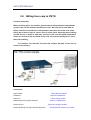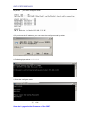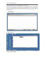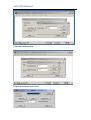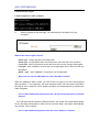
1
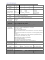
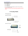
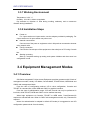
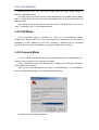
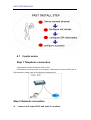
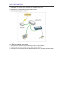
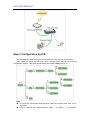
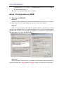
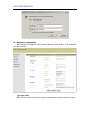
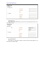
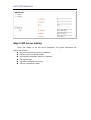
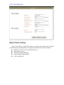
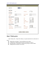
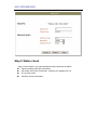
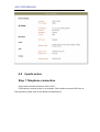
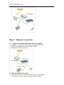
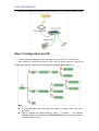
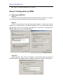
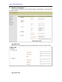
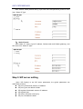
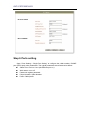
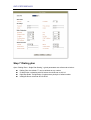
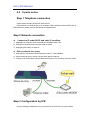
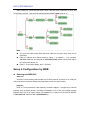
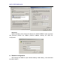
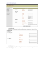
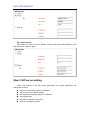
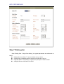
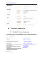
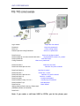
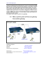
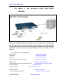
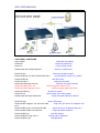
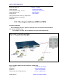
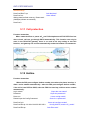
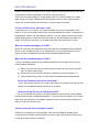
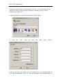
Multi Ports Gateway User Manual User Manual Multi Ports Gateway NOTE: For the usage of Multi Ports Gateway, please refer to IAD user manual. IAD USER MANUAL IAD user manual 1 VOIP instructions 1.1 VOIP VoIP (voice over IP) is an IP telephony term for a set of facilities used to manage the delivery of voice information over the Internet. VoIP involves sending voice information in digital form in discrete packets rather than by using the traditional circuit-committed protocols of the public switched telephone network (PSTN) a major advantage of VoIP and Internet telephony is that it avoids the tolls charged by ordinary telephone service. VoIP derives from the VoIP Forum, an effort by major equipment providers, including Cisco, VocalTec, 3Com, and Netspeak to promote the use of ITU-T H.323, the standard for sending voice (audio) and video using IP on the public Internet and within an intranet. The Forum also promotes the user of directory service standards so that users can locate other users and the use of touch-tone signals for automatic call distribution and voice mail. In addition to IP, VoIP uses the real-time protocol (RTP) to help ensure that packets get delivered in a timely way. Using public networks, it is currently difficult to guarantee Quality of Service (QOS). Better service is possible with private networks managed by an enterprise or by an Internet telephony service provider (ITSP). A technique used by at least one equipment manufacturer, Adir Technologies (formerly Netspeak), to help ensure faster packet delivery is to use ping to contact all possible network gateway computers that have access to the public network and choose the fastest path before establishing a Transmission Control Protocol TCP sockets connection with the other end. Using VoIP, an enterprise positions a "VoIP device" at a gateway. The gateway receives packetized voice transmissions from users within the company and then routes them to other parts of its intranet (local area or wide area network) or, using a T-carrier system or E-carrier interface, sends them over the public switched telephone network. IAD USER MANUAL 1.2 VOIP’S STRUCTURE It includes 4 elements in one VOIP structure: (1)Media Gateway:mainly change voice signal to IP package (2) Media Gateway Controller:that also is Gate Keeper and Call Server,mainly manage to transfer and change of signal. (3)voice server: manly supply voice response service when the phone can not connect or the phone is busy. (4) Signaling Gateway:mainly control the exchange process and supply increment service. 1.3 VOIP tech 1.3.1 H.323 An International Telecommunications Union that provides specification for equipment and services ,for communication over based networks that defines how real-time audio, video and data information is transmitted. H.323 is commonly used in and IP-based videoconferencing. Users can connect with other users over the and use varying products that support H.323. This standard is based on the Internet Engineering Task Force Real-Time Protocol and Real-Time Control Protocol ,with additional for, and audiovisual communications. 1.3.2 SIP The Session Initiation Protocol (SIP) is a signaling protocol used for establishing sessions in an IP network. A session could be a simple two-way telephone call or it could be a collaborative multi-media conference session. The ability to establish these sessions means that a host of innovative services become possible, such as voice-enriched e-commerce, web page click-to-dial, Instant Messaging with buddy lists, and IP Centrex services. Over the last couple of years, the Voice over IP community has adopted SIP as its protocol of choice for signaling. SIP is an RFC standard from the Internet Engineering Task Force (IETF), the body responsible for administering and developing the IAD USER MANUAL mechanisms that comprise the Internet. SIP is still evolving and being extended as technology matures and SIP products are socialized in the marketplace. The IETF's philosophy is one of simplicity: specify only what you need to specify. SIP is very much of this mould; having been developed purely as a mechanism to establish sessions, it does not know about the details of a session, it just initiates, terminates and modifies sessions. This simplicity means that SIP scales, it is extensible, and it sits comfortably in different architectures and deployment scenarios. SIP is a request-response protocol that closely resembles two other Internet protocols, HTTP and SMTP (the protocols that power the World Wide Web and email); consequently, SIP sits comfortably alongside Internet applications. Using SIP, telephony becomes another web application and integrates easily into other Internet services. SIP is a simple toolkit that service providers can use to build converged voice and multimedia services. In order to provide telephony services there is a need for a number of different standards and protocols to come together - specifically to ensure transport (RTP), to authenticate users (RADIUS, DIAMETER), to provide directories (LDAP), to be able to guarantee voice quality (RSVP, YESSIR) and to inter-work with today's telephone network. Here we will only cover SIP. 1.3.3 Codec The name "codec" is short for "coder-decoder," which is pretty much what a codec does. Most audio and video formats use some sort of compression so that they don't take up a ridiculous amount of disk space. Audio and video files are compressed with a certain codec when they are saved and then decompressed by the codec when they are played back. Common codecs include MPEG and AVI for video files and WAV and AIFF for audio files. Codecs can also be used to compress streaming media (live audio and video) which makes it possible to broadcast a live audio or video clip over a broadband Internet connection. 1.3.3 RTP RTP provides end-to-end network transport functions suitable for applications transmitting real-time data, such as audio, video or simulation data, over multicast or unicast network services. RTP does not address resource reservation and does not guarantee quality-of-service for real-time services. The data transport is augmented by a control protocol (RTCP) to allow monitoring of the data delivery in a manner scalable to large multicast networks, and to provide minimal control and identification functionality. RTP and RTCP are designed to be independent of the underlying transport and network layers. The protocol supports the use of RTP-level translators and mixers. IAD USER MANUAL 1.3.4 QOS In a general context, quality of service is a set of methods and processes a service-based organization implements to maintain a specific level of quality. In the context of networking, Quality of Service (QoS) refers to a combination of mechanisms that cooperatively provide a specific quality level to application traffic crossing a network or multiple, disparate networks. Implementing QoS means combining a set of IETF-defined technologies designed to alleviate the problems caused by shared network resources and finite bandwidth. 1.3.5 TCP/UDP Abbreviation of Transmission Control Protocol, and pronounced as separate letters. TCP is one of the main protocols in TCP/IP networks. Whereas the IP protocol deals only with packets, TCP enables two hosts to establish a connection and exchange streams of data. TCP guarantees delivery of data and also guarantees that packets will be delivered in the same order in which they were sent. Short for User Datagram Protocol, a connectionless protocol that, like TCP, runs on top of IP networks. Unlike TCP/IP, UDP/IP provides very few error recovery services, offering instead a direct way to send and receive datagrams over an IP network. It's used primarily for broadcasting messages over a network. UDP stands for User Datagram Protocol. It is described in STD-6/RFC-768 and provides a connectionless host-to-host communication path. UDP has minimal overhead: each packet on the network is composed of a small header and user data. It is called a UDP datagram. 2 IAD products introduction 3.1 Product description GW Series voice gateway product is IAD integrated access equipment for medium and minor enterprises, network operators, and telecommunication service operators; it is an ideal choice for the access of commercial network points, enterprise branches, end user data and IP voice. z Easy to establish network Support access of different kinds of internet environments, including ADSL and VPN, support PPPoE, with built-in "EasyTrans”proxy module, and can be used in different kinds of private networks. IAD USER MANUAL z Proxy server Support NAT conversion as well as DMZ and virtual server, can be used as proxy server for medium and minor enterprise to connect into Internet, to realize the simultaneous transmission of voice and data. It can increase the utilization of network resources. z Simple to config Plug and play, support RS232 config command line, TELNET as well as graphics interface of Web browser, support the DHCP dynamic IP and DNS automatic addressing. It owns patented IVR voice call keystroke configuration function, which can config the equipment simply without need of professional VoIP background, and thus decrease the technical requirements for installation. z Rich interface The product provides different kinds of analog interfaces including FXS/FXO, and has functions such as smart busy tone detection, smart voice detection, hang-up detection, DTMF detection, and antipole signal offering and detection. It can work together with different kinds of interface devices including normal telephone, incoming number display telephone, facsimile set, call center, and CTI voice card. It can also be used with SPC exchange and PSTN lines, and support antipole billing at the same time. z Excellent voice quality Adopt dedicated voice compression decoding chip and well-designed analog interface, support all kinds of coding decoding in H.323, including G.723.1 (5.3K), Shield G.723.1 (6.3K), G.729£¨A / B / AB£©, G.711Alaw / Ulaw and etc.; has the functions of echo elimination and background noise screening. The distortion of voice is very small, the volume is adjustable, and the voice quality is basically as same as traditional voice service. It is suit for different kinds of band width network environment. z Convenience for administration Adopt patented "EasyTrans”network administration technology, support remote management under private network/fire wall, can be managed in multilayer internal network, support multilevel user authentication management, and can also be upgraded via remote administration. z High security Support multiple administrator login and crypto protection, support different kinds of authentication mechanisms such as IP address, MAC address, H323ID, calling number, prefix, and H.235 password, can thus prevent effectively unauthorized calling. 3.2 Product Specification GW Series Name/model of indices GW0224 GW0225 GW0420 GW0421 GW0422 GW0820 GW0821 GW0822 GW1620 GW1621 GW1622 GW1623 IAD USER MANUAL Number of voice interface 2 4 8 Number of VOIP channel 2 4 8 Audio frequency interface(RJ11) 2FXS; 1FXS+1FXO 4FXS; 4FXO; 2FXS+2FXO Ethernet interface (RJ45) 2 10/100M Base-T Ethernet interfaces 8FXS; 8FXO; 4FXS+4FXO Serial interface (RJ45) 1 RS232 interface (CONSOLE administration port) VOIP protocol standards H323V2/V4 SIP V2.0 16 16 16FXS; 16FXO; 12FXS+4FXO; 8FXS+8FXO Voice encoding G.723.1 (5.3K 6.3K b/s),G.729 A/B(8K b/s),G.711 (64K b/s) Fax protocol T.38,T.30,FRF Voice quality TOS; JITTER BUFFER; VAD; Diff-Serve Network standards IEEE 802.3 ,IEEE 802.3u,IEEE 802.3x ,IEEE 802.1q,IEEE 802.1x Network protocols HTTP,BOOTP,FTP,TFTP,DHCP,PPPoE,SNMP,Diff-Serve Functional characteristics Echo elimination Intercommunication characteristics Power supply module Maximum power Built-in PPPoE and NAT, support DMZ and virtual server; DHCP, plug and play; Built-in "EasyTrans”proxy module; Support remote administration and voice penetration under private network/fire wall; Support telephone voice keystroke configuration and remote upgrading software functions; Incoming number display/incoming number identification (Call ID identification); System voice box, user defined voice prompt; Support DNS dynamic addressing and backup; Power-off escaping protection; Call diversion of IP network and PSTN network; Can config via configuration port, telnet, and web browser etc. G.168 (25-64ms) Compatible with mainstream VoIP products from CISCO, Notel, Lucent, Huawei, UT, etc. DC 5V 1000mA DC 12V 600mA AC 90-240V DC 12V/1A 5V/2A AC 90-240V DC 12V/2A 3.3V/5A 7W 7W 22W 40W Telephone line transmission range <500m Physical dimension 144mmX90mmX30mm 160mmX210mmX40mm 440mmX330mmX44mm 230G 1KG 3.5KG Weight Work environment Temperature: 0¡æ-50¡æ, humidity:10%-90%, without coagulation IAD USER MANUAL 3.2 Hardware Installation 3.2.1 List of articles GW Series Integrated IP Voice Access Equipment is classified into four sub-classes: 2 ports series (GW0224&GW0225), 4 ports series (GW0420&GW0421&GW0422), 8 ports series (GW0820&GW0821& GW0822), and 16 ports series (GW1620& GW1621& GW1622& GW1623). See the following table: series products 2 ports series GW0224 ,GW0225 4 ports series GW0420, GW0421, GW0422 8 ports series GW0820, GW0821, GW0822 16 ports series GW1620, GW1621, GW1622, GW1623 The packing list of articles is as follows: 3.2.1.2 2 Ports series one 2 ports series netphone router one 12V outlay power supply 1 installation CDROM and 1 product quick setting manual 1 guarantee card One Ethernet straight-thru cable (jasper) and one Ethernet crossover cable(grey) 1 CONSOLE line (matching with 2 ports series PLUS) 3.2.1.3 4 ports series one 4 ports series access equipment 1 12V outlay power supply 1 installation CDROM 1 guarantee card 1 Ethernet straight-thru cable (jasper) and 1 Ethernet crossover cable(grey) 1 CONSOLE line 3.2.1.4 8 ports series and 16 ports series one 8 ports series/ 16 ports series access equipment IAD USER MANUAL 1 power cord 1 installation CDROM 1 telephone line 1 guarantee card 1 CONSOLE line 1 Ethernet straight-thru cable (jasper) and 1 Ethernet crossover cable(grey) 1 pair of hangers, 4 screws Explanation: The changes of list of articles resulted from upgrading or revision of equipment will not be further notices, and the company keeps the final right to interpret. 3.3 Facility Profile 3.3.2 2 ports series 2 ports series’ front panel: 2 ports series’ rear panel: IAD USER MANUAL 3.3.3 4 ports series 4 ports series’ front panel: 3.3.4 8 ports series 8 ports series’ front panel: 3.3.5 Explanation of LED Notes: When the equipment is started, all the leds in front panel will light. Then after starting up, POWER led is light, and Active Led is flash in certain frequency. The following is explanation of LED. Power(Green) It indicates the power supply is normal Active(Green) Its flash in certain frequency indicates the normal working of kernel software Phone / Line X(Green) It indicates the corresponding Phone/Line interface is in use when it is light. Otherwise it is not light. It is displayed as Phone in 2 ports series and Line in 4 ports series, 8 ports series and IAD USER MANUAL 16 ports series. PSTN (green) It indicates the corresponding interface is in use when it is light. Otherwise it is not light. This LED only exists in 2 ports series 1FXS+1FXO. Tx / Rx (green) Indicator for sending-receiving of network interface. When data pass through, it will flash in certain frequency. This LED only exists in 4 ports series. 10BASE-T / 100BASE-T (green) Indicator for network interface. Keep light after connected. This LED only exists in 4 ports series. 3.3.6 Interface Specification PC / 100BASE-T 100M bps RJ45 Ethernet interface Used to connect computer. The computer, after certain config, can share internet connection via the equipment. Use cross wire when direction connection. [Notice: if connected to computer, LED in GW and the LED corresponding to PC network adapter shall both be light] WAN / 10BASE-T 100M bps RJ45 Ethernet interface (10M labeled in 4 ports series) For DSL Modem dial, use parallel line to connect directly. This port can connect to also other LAN interface. Console Connect to PC serial port, used to config the equipment in HyperTerminal mode via PC. Phone /FXS It is displayed as Phone in 2 ports series and FXS in 4 ports series , 8 ports series and 16 ports series. Connect telephone directly PSTN / FXO It is displayed as PSTN in 2 ports series and FXO in 4 ports series , 8 ports series and 16 ports series. Connect to PSTN line or extension line of SPC exchange IAD USER MANUAL 3.3.7 Working Environment Temperature: 0~50°C Humidity: 10%-90%, without coagulation Pay attention to rejection of heat during working, stationary and no strenuous vibration during installation. 3.3.8 Installation Steps Power on For 2 ports series and 4 ports series, use the adapter provided in packaging. For 8 ports series and 16 ports series use power cord. Network connections Connect one of the ports on equipment to the LAN port that connected to Internet using network wire. Config connection Connect the Console port of the equipment to the serial port of PC using Console line. Starting up testing Start up, complete starting up testing and system initiation and then enter into configuration mode. 3.4 Equipment Management Modes 3.4.1 Overview GW Series Integrated IP Voice Access Equipment provides customers with 5 kinds of management modes, namely: IVR Mode, Console Mode, TELNET Mode, WEB Mode and CMCC tele management Mode. From the view of configuration method: IVR is voice configuration, Console and TELNET is command line, while WEB and CMCC is graphics interface. From the view of administration range: IVR and Console can only be performed in local site, while TELNET, WEB and CMCC can be realized remotely. When login equipment via Console, TELNET or WEB mode, "User/Password”is required to authenticate user. When in CMCC tele management mode, only "Password”is required Notes: No authentication is adopted in default IVR mode (It is suggested to set IVR configuration password via Console mode) IAD USER MANUAL Default system user: root. There are Config mode and Super mode basing on different configuration level. In Config mode you can set common user parameters such as called number, dialing rules; in Super mode you can set system parameters such as H.323 information and calling number. After loging system successfully via Console mode or TELNET mode, you can use "help + Command” and "?” to get related help info. 3.4.2 IVR Mode IVR Configuration System (Hereafter as CICS) is a communication product configuration system, which can carry out conventional configuration on the working parameters of VoIP gateways as well query functions. A telephone line is connected directly to the RJ11 port of the gateway. It is simple, flexible and convenient. 3.4.3 Console Mode You can config the equipment using the HyperTerminal software in Windows 9X / NT / 2000 / XP via Console port, the steps are as follows: Firstly, connect the Console port (RJ45) to the COM port on PC using the serial wire in the packing of the product. Then run the HyperTerminal in the folder of "Communication” in "Accessories", selects corresponding serial port, as showed in following figure: Config the port parameters as follows: IAD USER MANUAL Set terminal parameters: resume default is OK 3.4.4 TELNET Mode After determine the IP address of WAN port (default is 192.168.0.235) or LAN port (can query the address via IVR) of the equipment Config PC and gateway in same sub-network, confirm the PC can ping the gateway, input telnet 192.168.0.235 (IP address of equipment) and then operate according to the related hints. 3.4.5 WEB Mode GW Series Integrated IP Voice Access Equipment offers WEB configuration interface, which is suit for Microsoft Windows Operating System. You can perform WEB administration via port or LAN port. Taking WAN port address 192.168.0.227 as example, ping 192.168.0.227 in PC, confirm the computer can connect to WAN port, then start browser, input http://192.168.0.227 in browser's address bar, and type return to enter into the login interface of Web. IAD USER MANUAL 4.1 2 ports series Step 1 Telephone connection 2 ports series includes 2FXS and 1FXS+1FXO. FXS interface connects phone or fax machine. FXO interface connects PSTN line or PBX extension, please care for the difference between them. Step 2 Network connection z Connect to IP under DHCP and static IP condition. IAD USER MANUAL 1)Adaptable for company and household who installed inside LAN. 2)WAN port of 2 ports series connects HUB or Switch. 3)WAN port gets DHCP or static IP. z Dial-up network as a proxy 1)WAN port 2 ports series connects directly to xDSL ( Cable) Modem. 2)2 ports series as proxy, mainly used to share dial-up network. 3)LAN port of 2 ports series connects Network interface of PC by using crossover Cable. IAD USER MANUAL Step 3 Configuration by IVR Connect analogue telephone to any one Phone Port (FXS Port) of 2 ports series. After holding up, press the star keys“*”twice, user can hear “welcome to enter IVR configuration system”, and input the password (the default is 888), and go on. Note The port with 10M means WAN port and 100M for LAN port when voice cue is appeared. Enter IP address and Subnet mask by using “*” to replace “.”. For example, IAD USER MANUAL 192.168. 0.215 can be changed for 192*168*0*215#, please note the last step is to confirm with the key “#”. Enter“1” to quit after setting, and “1”for save. Setup 4 Configuration by WEB z Entering into WEB GUI Step one Choose PC after setting network card and TCP/IP protocol. Connect PC to LAN port of 2 ports series crossover cable (using other device such as HUB, Switch.) Step two Pitch on “Local connection” after opening “network neighbor”. Hit right key to choose property such as below picture. Configure IP address of PC to be in the same network segment with LAN IP of 2 ports series. (The default IP of LAN port for 2 ports series is 192.169.0.235, subnet mask is 255.255.255.0.) Step three: Open IE browser, enter LAN port IP address of 2 ports series. Input user name and password (default user: admin. password: admin), entering into WEB GUI configuration. IAD USER MANUAL z Network configuration After entering into WEB GUI, open “Network Setting > WAN Setting”, it can be divided into three modes.) 1)DHCP mode Start “DHCP” mode (using DHCP to get IP address) and save from “Select IP Type”. IAD USER MANUAL 2)PPPoE mode Start “PPPoE” mode (PPPoE dial-up, input user name and password), and then save from “Select IP Type”. 3) Static IP mode Start “Static IP” mode (input IP address, Subnet mask and Default gateway), and then save from “Select IP Type”. IAD USER MANUAL Step 5 SIP server setting Open “SIP setting” to set SIP server parameters, the typical parameters are referenced as below: SIP proxy, like domain name or IP address. SIP proxy port, the default is 5060. SIP registrar, like domain name or IP address. SIP registrar port. SIP realm, the same is SIP proxy. SIP port, the default is 5060. IAD USER MANUAL Step 6 Ports setting Open “Ports Setting > Single Port Setting” to configure the caller number, PHONE port (PSTN port) other parameters. The typical parameters are referenced as below: Select Port: Line0 or Line1 (the different port no.). Work status: on or off. Password: register password. Phone Number: Caller Number. Prefix: Called prefix. IAD USER MANUAL Step 7 Dialing plan Open “Dialing Plan > Single Plan Setting”, the typical parameters are referenced as below: Dialing Plan: the default “T” can be defined as any number. IP Map Rules: registering with GK where should be set as 0.0.0.0 Digit Map Rules: configuration of replacement principle of called number. Intelligent Route: aimed at 1FXS+1FXO IAD USER MANUAL Step 8 Status check Open “Current Status”, the typical parameters are referenced as below: Ethernet setting, WAN port information. SIP setting, SIP server information. Checking it if registered or not. The current Codec Software version information. IAD USER MANUAL 4.2 4 ports series Step 1 Telephone connection 8 ports series includes 2FXS and 1FXS+1FXO. FXS interface connects phone or fax machine. FXO interface connects PSTN line or PBX extension, please care for the difference between them. IAD USER MANUAL Step 2 z Network connection Connect to IP under DHCP and static IP condition. 1)Adaptable for company and household who installed inside LAN. 2)WAN port of 4 ports series connects HUB or Switch. 3)WAN port gets DHCP or static IP. z Dial-up network as a proxy 1)WAN port 4 ports series connects directly to xDSL ( Cable) Modem. 2)4 ports series as proxy, mainly used to share dial-up network. IAD USER MANUAL 3)LAN port of 4 ports series connects Network interface of PC by using crossover Cable. Step 3 Configuration by IVR Connect analogue telephone to any one Phone Port (FXS Port) of 4 ports series. After holding up, press the star keys“*”twice, user can hear “welcome to enter IVR configuration system”, and input the password (the default is 888), and go on. Note The port with 10M means WAN port and 100M for LAN port when voice cue is appeared. Enter IP address and Subnet mask by using “*” to replace “.”. For example, 192.168. 0.215 can be changed for 192*168*0*215#, please note the last step is to confirm with the key “#”. IAD USER MANUAL Enter“1” to quit after setting, and “1”for save. Setup 4 Configuration by WEB z Entering into WEB GUI Step one Choose PC after setting network card and TCP/IP protocol. Connect PC to LAN port of 4 ports series crossover cable(using other device such as HUB, Switch.) Step two Pitch on “Local connection” after opening “network neighbor”. Hit right key to choose property such as below picture. Configure IP address of PC to be in the same network segment with LAN IP of 4 ports series. (The default IP of LAN port for 4 ports series is 192.169.0.235, subnet mask is 255.255.255.0.) Step three: Open IE browser, enter LAN port IP address of 4 ports series. Input user name and password (default user: admin. password: admin), entering into WEB GUI configuration. IAD USER MANUAL z Network configuration After entering into WEB GUI, open “Network Setting > WAN Setting”, it can be divided into three modes.) 1)DHCP mode Start “DHCP” mode (using DHCP to get IP address) and save from “Select IP Type”. 2)PPPoE mode IAD USER MANUAL Start “PPPoE” mode (PPPoE dial-up, input user name and password), and then save from “Select IP Type”. 3) Static IP mode Start “Static IP” mode ( input IP address, Subnet mask and Default gateway), and then save from “Select IP Type”. Step 5 SIP server setting Open “SIP Setting” to set SIP server parameters, the typical parameters are referenced as below: SIP proxy, like domain name or IP address. SIP proxy port, the default is 5060. SIP registrar, like domain name or IP address. SIP registrar port. SIP realm, the same is SIP proxy. SIP port, the default is 5060. IAD USER MANUAL Step 6 Ports setting Open “Ports Setting > Single Port Setting” to configure the caller number, PHONE port (PSTN port) other parameters. The typical parameters are referenced as below: Select Port: Line0 or Line1 (the different port no.). Work status: on or off. Password: register password. Phone Number: Caller Number. Prefix: Called prefix. IAD USER MANUAL Step 7 Dialing plan Open “Dialing Plan > Single Plan Setting”, typical parameters are referenced as below: Dialing Plan: the default “T” can be defined as any number. IP Map Rules: registering with GK where should be set as 0.0.0.0 Digit Map Rules: configuration of replacement principle of called number. Intelligent Route: aimed at 2FXS+2FXO IAD USER MANUAL Step 8 Status check Open “Current Status”, the typical parameters are referenced as below: Ethernet setting, WAN port information. SIP setting, SIP server information. Checking it if registered or not. The current Codec Software version information. IAD USER MANUAL 4.3 8 ports series Step 1 Telephone connection 8 ports series includes 2FXS and 4FXS+4FXO. FXS interface connects phone or fax machine. FXO interface connects PSTN line or PBX extension, please care for the difference between them. Step 2 Network connection z Connect to IP under DHCP and static IP condition. 1)Adaptable for company and household who installed inside LAN. 2)WAN port of 8 ports series connects HUB or Switch. 3)WAN port gets DHCP or static IP. z Dial-up network as a proxy 1)WAN port 8 ports series connects directly to xDSL ( Cable) Modem. 2)8 ports series as proxy, mainly used to share dial-up network. 3)LAN port of 8 ports series connects Network interface of PC by using crossover Cable. Step 3 Configuration by IVR Connect analogue telephone to any one Phone Port (FXS Port) of 8 ports series. IAD USER MANUAL After holding up, press the star keys“*”twice, user can hear “welcome to enter IVR configuration system”, and input the password (the default is 888), and go on. Note The port with 10M means WAN port and 100M for LAN port when voice cue is appeared. Enter IP address and Subnet mask by using “*” to replace “.”. For example, 192.168. 0.215 can be changed for 192*168*0*215#, please note the last step is to confirm with the key “#”. Enter“1” to quit after setting, and “1”for save. Setup 4 Configuration by WEB z Entering into WEB GUI Step one Choose PC after setting network card and TCP/IP protocol. Connect PC to LAN port of 8 ports series crossover cable(using other device such as HUB, Switch.) Step two Pitch on “Local connection” after opening “network neighbor”. Hit right key to choose property such as below picture. Configure IP address of PC to be in the same network segment with LAN IP of 8 ports series. (The default IP of LAN port for 8 PORTS SERIES is 192.169.0.235, subnet mask is 255.255.255.0.) IAD USER MANUAL Step three: Open IE browser, enter LAN port IP address of 8 PORTS SERIES. Input user name and password (default user: admin. password: admin), entering into WEB GUI configuration. z Network configuration After entering into WEB GUI, open “Network Setting > WAN Setting”, it can be divided into three modes.) IAD USER MANUAL 1)DHCP mode Start “DHCP” mode (using DHCP to get IP address) and save from “Select IP Type”. 2)PPPoE mode Start “PPPoE” mode (PPPoE dial-up, input user name and password), and then save from “Select IP Type”. IAD USER MANUAL 3) Static IP mode Start “Static IP” mode ( input IP address, Subnet mask and Default gateway), and then save from “Select IP Type”. Step 5 SIP server setting Open “SIP Setting” to set SIP server parameters, the typical parameters are referenced as below: SIP proxy, like domain name or IP address. SIP proxy port, the default is 5060. SIP registrar, like domain name or IP address. SIP registrar port. SIP realm, the same is SIP proxy. SIP port, the default is 5060. IAD USER MANUAL Step 6 Ports setting Open “Ports Setting > Single Port Setting” to configure the caller number, PHONE port (PSTN port) other parameters. The typical parameters are referenced as below: Select Port: Line0 or Line1 (the different port no.). Work status: on or off. Password: register password. Phone Number: Caller Number. Prefix: Called prefix. IAD USER MANUAL Step 7 Dialing plan Open “Dialing Plan > Single Plan Setting”, the typical parameters are referenced as below: Dialing Plan: the default “T” can be defined as any number. IP Map Rules: registering with GK where should be set as 0.0.0.0 Digit Map Rules: configuration of replacement principle of called number. Intelligent Route: aimed at 2FXS+2FXO IAD USER MANUAL Step 8 Status check Open “Current Status”, the typical parameters are referenced as below: Ethernet setting, WAN port information. SIP setting, SIP server information. Checking it if registered or not. The current Codec Software version information. IAD USER MANUAL 5 Function introduce 5.1 Config IP address of gateway There are three ways for configure IP address of gateway : DHCP, PPPOE ,static ip. One command way: Static IP setting Login: admin Password: Root>con Please input the Config Password: //input the user name// //input the password// // enter config mode// //here is no password// Root/Conf>e0 //enter e0 configure mode// Root/Conf/E0>ip 192.168.0.24 255.255.255.0 //config WAN IP, and the IP_mask// Root/Conf/E0>qu //exit E0 mode// Root/Conf>route add default 192.168.0.1 //config route// Root/Conf>wr //save these// Writing data into flash memory. Please wait... (550Bytes) Written successfully. DHCP setting IAD USER MANUAL Login: admin Password: Root>con Please input the Config Password: //input the user name// //input the password// // enter config mode// //here is no password// Root/Conf>e0 Root/Conf/E0>dhcp //enter e0 configure mode// //set DHCP, it can get IP address and route automatically // Dhcp client start up! Please wait...... Root/Conf/E0> qu Root/Conf>wr Writing data into flash memory. Please wait... (550Bytes) Written successfully. //exit E0 mode// //save these// PPPOE setting, if the PPPOE account is root, the password is 123456 Login: admin //input the user name// Password: //input the password// Root>con // enter config mode// Please input the Config Password: //here is no password// Root/Conf>e0 Root/Conf/E0>pppoe root 123456 Root/Conf/E0> qu Root/Conf>wr Writing data into flash memory. Please wait... (550Bytes) Written successfully. //enter e0 configure mode// //set PPPOE// //exit E0 mode// //save these// Note: 1 if here can not use the DHCP and PPPOE, use following command, Root/Conf/E0> //enter e0 configure mode// Root/Conf/E0>no dhcp //cancel DHCP// Root/Conf/E0>no pppoe //cancel PPPOE// 2 when the gateway use the static IP and you change to another static IP address, you must set the default route again. 5.2 Make a point to point call in one gateway POINT TO POINT in a gateway, that is 100 call 101 or 101 call 100. IAD USER MANUAL Login: admin Password: Root>con Please input the Config Password: //input the user name// //input the password// // enter config mode// //here is no password// Root/Conf>e0 //enter e0 configure mode// Root/Conf/E0>ip 192.168.0.24 255.255.255.0 //config WAN IP, and the IP_mask// Root/Conf/E0>qu //exit E0 mode// Config Password: //here is no password// Root/Conf>line 0 Root/Conf/Line0>pre add 100 //enter line 0 mode// //add line 0’s prefix number// Root/Conf/Line0>q //exit line 0 mode// Root/Conf>line 1 //enter line 1 node// Root/Conf/Line1>pre add 101 //add line 1’s prefix number// Root/Conf/Line1>q //exit line 1 mode// Root/Conf>dial t //configure dial plan// Root/Conf/Dial T>map 127.0.0.1 //config map IP address// Root/Conf/Dial T>qu //exit dial plan// Root/Conf>wr //save these// Writing data into flash memory. Please wait... (583Bytes) Written successfully. Root/Conf> Note: if you make a call from VOIP to PSTN, you let the phone port IAD USER MANUAL connect a original phone and the pstn port connect a external line of PBX, then when you call the pstn port’s prefix number, you can hear a second dialtone, then you dial the another external number of PBX, it'll connect. If you make a call from PSTN to VOIP, you let the phone port connect a original phone and the pstn port connect a external line of PBX, then you call the number that connect a external line of PBX from another external number of PBX, you can hear a second dialtone, then you dial the line 0 prefix number, it'll connect. It configures all like point to point in one gateway. 5.3 Make a point to point call from one gateway from another gateway A gateway configures: Login: admin Password: Root>con Please input the Config Password: Root/Conf>e0 Root/Conf/E0>ip 192.168.0.55 255.255.255.0 Root/Conf/E0>qu //input the user name// //input the password// // enter config mode// //here is no password// //enter e0 configure mode// //config WAN IP, and the IP_mask// //exit E0 mode// IAD USER MANUAL Root/Conf>line 0 //enter line 0 mode// Root/Conf/Line0>pre add 100 //add line 0’s prefix number// Root/Conf/Line0>q //exit line 0 mode// Root/Conf>line 1 //enter line 1 node// Root/Conf/Line1>pre add 101 //add line 1’s prefix number// Root/Conf/Line1>q //exit line 1 mode// Root/Conf>dial t //configure dial plan// Root/Conf/Dial T>map 192.168.0.56 //config map IP address// Root/Conf/Dial T>qu //exit dial plan// Root/Conf>wr //save these// Writing data into flash memory. Please wait... (583Bytes) Written successfully. Root/Conf> B gateway configures: Login: admin Password: Root>con Please input the Config Password: //input the user name// //input the password// // enter config mode// //here is no password// Root/Conf>e0 //enter e0 configure mode// Root/Conf/E0>ip 192.168.0.56 255.255.255.0 //config WAN IP, and the IP_mask// Root/Conf/E0>qu //exit E0 mode// Config Password: //here is no password// Root/Conf>line 0 //enter line 0 mode// Root/Conf/Line0>pre add 200 //add line 0’s prefix number// Root/Conf/Line0>q //exit line 0 mode// Root/Conf>line 1 //enter line 1 node// Root/Conf/Line1>pre add 201 //add line 1’s prefix number// Root/Conf/Line1>q //exit line 1 mode// Root/Conf>dial t //configure dial plan// Root/Conf/Dial T>map 192.168.0.55 //config map IP address// Root/Conf/Dial T>qu //exit dial plan// Root/Conf>wr //save these// Writing data into flash memory. Please wait... (583Bytes) Written successfully. Root/Conf> IAD USER MANUAL 5.4 Make a call between VOIP and PSTN directly We have the FXS+FXO gateway, the FXS port connects original phone, and the FXO port connects the extensional line of PBX, if so the gateway can call VOIP and PSTN. General FXS calls FXO, and then calls PSTN again or PSTN call FXO, then calls FXS, please see 5.2. Here instructs that FXS call PSTN directly, or PSTN calls FXS directly. For example, 100 call 254 directly: Login: admin Password: Root>con Please input the Config Password: //input the user name// //input the password// // enter config mode// //here is no password// Root/Conf>e0 //enter e0 configure mode// Root/Conf/E0>ip 192.168.0.24 255.255.255.0 //config WAN IP, and the IP_mask// Root/Conf/E0>qu //exit E0 mode// Config Password: //here is no password// Root/Conf>line 0 Root/Conf/Line0>pre add 100 Root/Conf/Line0>q //enter line 0 mode// //add line 0’s prefix number// //exit line 0 mode// IAD USER MANUAL Root/Conf>line 4 //enter line 4 node// Root/Conf/Line4>pre add 104 //add line 4’s prefix number// Root/Conf/Line4>q //exit line 4 mode// Root/Conf>dial t //configure dial plan// Root/Conf/Dial T>map 127.0.0.1 //config map IP address// Root/Conf/Dial T>pstn 1 // config go pstn force// Root/Conf/Dial T>qu //exit dial plan// Root/Conf>wr //save these// Writing data into flash memory. Please wait... (583Bytes) Written successfully. Root/Conf> Note: Disable (pstn -1), all call will go to VOIP. Force (pstn 1), all calls will go to PSTN. Auto (pstn 0), when the VOIP disconnects, then go to PSTN. For example, 254 call 100 directly: We set oppchan in port setting interface, for example, here is 4FXS+4FXO gateway, we set oppchan line 0 to line 4, then the call that is from PSTN to VOIP, the line 0 ring, there is no needing the second dialing. But here some different, the PSTN 254 must dial 253, then 100 rings. Login: admin //input the user name// Password: //input the password// Root>con // enter config mode// Please input the Config Password: //here is no password// Root/Conf>e0 //enter e0 configure mode// Root/Conf/E0>ip 192.168.0.24 255.255.255.0 //config WAN IP, and the IP_mask// Root/Conf/E0>qu //exit E0 mode// Root/Conf>line 0 //enter line 0 mode// Root/Conf/Line0>pre add 100 //add line 0’s prefix number// Root/Conf/Line0>oppchan 4 //set relative line 4// Root/Conf/Line0>q //exit line 0 mode// Root/Conf>line 4 //enter line 4 node// Root/Conf/Line4>pre add 104 //add line 4’s prefix number// Root/Conf/Line4>oppchan 0 //set relative line 0// Root/Conf/Line4>q //exit line 4 mode// Root/Conf>dial t //configure dial plan// Root/Conf/Dial T>map 127.0.0.1 //config map IP address// Root/Conf/Dial T>qu //exit dial plan// Root/Conf>wr //save these// Writing data into flash memory. Please wait... (583Bytes) Written successfully. IAD USER MANUAL 5.5 Make a call between VOIP and PSTN directly The register parameters includes register server’ address, register server port, proxy address, proxy port, outbound proxy address, outbound proxy port, realm address, register user ,register password in standard SIP protocol. Register server’ address, register server port, proxy address, proxy port, realm address, register user, register password must input in gateways, others are decided by server’s requirement. Our SIP server—XMC need input register server’ address, register server port, proxy address, proxy port, realm address, register user, register password. Register server address: SIP register’s IP or domain name Register port: the port is that exchanges signal with register server, the default is 5060 Proxy server address: SIP proxy server’s IP address, generally it is the same with the register IP address, if you input wrong proxy server, it can register but can not call. Proxy port: SIP proxy server’s port, generally it is the same with the register port. Outbound proxy server: it is often used transfer media then the media of gateways in NAT is disconnected. Realm address: manage realm Register user: every line has register user. Register password: every: line has register password For example: Sip server: 192.168.0.50 Sip account: 100 200 Password: 1001 2001 Then 100 call 200, or 200 call 100 IAD USER MANUAL A GATEWAY CONFIGURE Login: admin Password: Root>con Please input the Config Password: //input the user name// //input the password// // enter config mode// //here is no password// Root/Conf>e0 //enter e0 configure mode// Root/Conf/E0>ip 192.168.0.55 255.255.255.0 //config WAN IP, and the IP_mask// Root/Conf/E0>qu //exit E0 mode// Root/Conf>line 0 //enter line 0 mode// Root/Conf/Line0>pre add 100 //add line 0’s prefix number// Root/Conf/Line0>num 100 //set line register number 100// Root/Conf/Line0>password 1001 //set line register password 1001// Root/Conf/Line0>q //exit line 0 mode// Root/Conf>su //enter super user config mode// Please input the Super Password: //input the super password: admin// Root/Conf>sip //enter SIP mode// Root/Conf/SIP>register 192.168.0.50 5060 //input the SIP server IP address and port// Root/Conf/SIP>proxy 192.168.0.50 5060 //input the proxy IP address and port // Root/Conf/SIP>realm 192.168.0.50 //input the realm address// Root/Conf/SIP>qu //exit SIP mode// Root/Conf/Dial T>map 0.0.0.0 //config map IP address// Root/Conf/Dial T>qu //exit dial plan// IAD USER MANUAL Root/Conf>wr //save these// Writing data into flash memory. Please wait... (609Bytes) Written successfully. B GATEWAY CONFIGURE Login: admin Password: Root>con Please input the Config Password: //input the user name// //input the password// // enter config mode// //here is no password// Root/Conf>e0 //enter e0 configure mode// Root/Conf/E0>ip 192.168.0.56 255.255.255.0 //config WAN IP, and the IP_mask// Root/Conf/E0>qu //exit E0 mode// Root/Conf>line 0 //enter line 0 mode// Root/Conf/Line0>pre add 200 //add line 0’s prefix number// Root/Conf/Line0>num 200 //set line register number 200// Root/Conf/Line0>password 2001 //set line register password 2001// Root/Conf/Line0>q //exit line 0 mode// Root/Conf>su //enter super user config mode// Please input the Super Password: //input the super password: admin// Root/Conf>sip //enter SIP mode// Root/Conf/SIP>register 192.168.0.50 5060 //input the SIP server IP address and port// Root/Conf/SIP>proxy 192.168.0.50 5060 //input the proxy IP address and port // Root/Conf/SIP>realm 192.168.0.50 //input the realm address// Root/Conf/SIP>qu //exit SIP mode// Root/Conf/Dial T>map 0.0.0.0 //config map IP address// Root/Conf/Dial T>qu //exit dial plan// Root/Conf>wr //save these// Writing data into flash memory. Please wait... (609Bytes) Written successfully. 5.6 IVR system manage Function instruction: You can use IVR to check and configure the gateway. It is convenient using IVR, only press the phone button, if the gateway has FXS port, you can use a original phone to connect directly the FXS port; if the gateway has no FXS port, only has FXO port, you can connect a extension line to the FXO port, then you dial the extension number, then dial **, you can configure it. Command configures instruction: 1) ivrkey, that is which do you press button on phone to enter IVR system, the default is ** 2) configure or start IVR, enable is in using, disable is not in using. IAD USER MANUAL 3) configure the IVR password, the default is 888. 4) configure IVR is locked or not, and voice is used. Login: admin //input the user name// Password: //input the password// Root>con // enter config mode// Please input the Config Password: //here is no password// Root/Conf>app //enter app mode// Root/Conf/App>ivr //enter ivr mode// Root/Conf/App/Ivr> //show ivr parameters// Root/Conf/App/Ivr>sh -------ivr show------------------------------------------------ivrlock : no ivrreport : Enable ivrconfig : Enable ivrpassword : language : Chinese ivrkey : ** *9 : Produce a general secret key. *1 : Set an ip static address (123.123.123.123). *0 : Delete a static ip adrress (123.123.123.123). ---------------------------------------------------------------Root/Conf/App/Ivr> 5.7 Manage user authority Function instruction Here are two kinds, first is managing three loging way that is configure their login IP address and port. Second is configure user authority, here are original user and super user, the super have all authority, and they can configure authority of original user. Configure telnet login’s IP and port Login: admin // the default is admin // Password: admin // the default password is admin // Root>con // enter con mode // Root/Conf>admin // enter Admin mode // Root/Conf/Admin>telconf 192.168.2.74 23 //configure the telnet login IP address and port, the default is 23// Configure WEB login’s IP and port Login: admin Password: admin Root>con Root/Conf>admin Root/Conf/Admin>webconf 192.168.2.74 80 port, the default is 80// // the default is admin // // the default password is admin // // enter con mode // // enter Admin mode // //configure the web login IP address and IAD USER MANUAL 5.8 Display call ID and defect call ID Function instruction If you want to your phone that connects the FXS port can display the call ID, you must open the fxs port’s call ID switch (the phone must support the display function), now here are 2 mode ,FSK and DTMF. Display call ID: 1、 phone A------ A gateway’s FXS port ------ B gateway’s FXS port ------phone B If we want to phone B display phone A’s call ID, we must open call ID switch, that sets FSK or DTMF, and meantime set A gateway’s number. B gateway’s configure Root/Conf>line //set all line’s parameters // Root/Conf/LineAll>display fsk // set all line open display call ID switch// Root/Conf/LineALL>quit // quit line mode // Root/Conf>write // save these// A gateway’s configure Root/Conf>line //set all line’s parameters // Root/Conf/LineAll>number 91000 Root/Conf/LineALL>quit // set all line number are: 91000 // //quit line mode // Root/Conf>write // save these // 2、 phone A------ A gateway’s FXS port ------ B gateway’s FXO port ------PSTN If we want to phone A display call ID from PSTN, We need to open A gateway’s FXS port and B gateway’s FXO port’s switch, configure is following: A gateway’s configure Root/Conf>line //set all line’s parameters // Root/Conf/LineAll>display fsk Root/Conf/LineALL>quit // set all line open display call ID switch// // quit line mode // Root/Conf>write // save these// B gateway’s configure Root/Conf>line //set all line’s parameters // Root/Conf/LineAll>display fsk Root/Conf/LineAll>number 91000 Root/Conf/LineALL>quit Root/Conf>write //set all line open display call ID switch// // set all line number are: 91000 // //quit line mode // // save these // IAD USER MANUAL 5.9 Billing from voip to PSTN Function instruction When we billing with a line number, general start to billing when the called hands up that is the call line and the called line are ‘talk’. But if the call is from VOIP to PSTN, it need to second dial the called number, then there has some error about billing. So we have 2 ways to solve it. First is invert check, when the call are dialing second, the line ‘s status is ‘wait start’. the line is ‘talk ’until the PSTN called phone hands up. Second is find voice that is when the call hear the called phone’s voice, then start to billing. For example: 100 calls 254, 100 must dial 104,then dial 254, so the call can connect successfully . Invertcheck Login: admin Password: Root>con Please input the Config Password: Root/Conf>e0 Root/Conf/E0>ip 192.168.0.24 255.255.255.0 //input the user name// //input the password// // enter config mode// //here is no password// //enter e0 configure mode// //config WAN IP, and the IP_mask// IAD USER MANUAL Root/Conf/E0>qu Config Password: Root/Conf>line 0 Root/Conf/Line0>pre add 100 Root/Conf/Line0>num 100 Root/Conf/Line0>invertcheck Root/Conf/Line0>q Root/Conf>line 4 Root/Conf/Line4>pre add 104 Root/Conf/Line4>num 104 //exit E0 mode// //here is no password// //enter line 0 mode// //add line 0’s prefix number// //set the line number is 100 // //open invertcheck// //exit line 0 mode// //enter line 1 node// //add line 1’s prefix number// //set the line number is 104// Root/Conf/Line4>invertcheck //open invertcheck// Root/Conf/Line4>q //exit line 1 mode// Root/Conf>dial t //configure dial plan// Root/Conf/Dial T>map 127.0.0.1 //config map IP address// Root/Conf/Dial T>qu //exit dial plan// Root/Conf>wr //save these// Writing data into flash memory. Please wait... (583Bytes) Written successfully. Root/Conf> find voice Login: admin Password: Root>con Please input the Config Password: //input the user name// //input the password// // enter config mode// //here is no password// Root/Conf>e0 //enter e0 configure mode// Root/Conf/E0>ip 192.168.0.24 255.255.255.0 //config WAN IP, and the IP_mask// Root/Conf/E0>qu //exit E0 mode// Config Password: //here is no password// Root/Conf>line 0 Root/Conf/Line0>pre add 100 Root/Conf/Line0>num 100 Root/Conf/Line0>find voice 3 Root/Conf/Line0>q Root/Conf>line 4 Root/Conf/Line4>pre add 104 Root/Conf/Line4>num 104 Root/Conf/Line4>find voice 3 //enter line 0 mode// //add line 0’s prefix number// //set the line number is 100 // //open find voice// //exit line 0 mode// //enter line 1 node// //add line 1’s prefix number// //set the line number is 104// //open find voice// IAD USER MANUAL Root/Conf/Line4>q //exit line 1 mode// Root/Conf>dial t //configure dial plan// Root/Conf/Dial T>map 127.0.0.1 //config map IP address// Root/Conf/Dial T>qu //exit dial plan// Root/Conf>wr //save these// Writing data into flash memory. Please wait... (583Bytes) Written successfully. Root/Conf> 5.10 The simple dial from VOIP to PSTN Function instruction If we especially set line’s prefix or dial plan, we can not hear second dialtone and call the PSTN directly. For example: 100 calls 254, we make the call from 100 to 254 directly Phone 100 dial 104254, then the extension number ring. Login: admin //input the user name// Password: //input the password// Root>con // enter config mode// Please input the Config Password: //here is no password// Root/Conf>e0 //enter e0 configure mode// IAD USER MANUAL Root/Conf/E0>ip 192.168.0.24 255.255.255.0 //config WAN IP, and the IP_mask// Root/Conf/E0>qu //exit E0 mode// Config Password: //here is no password// Root/Conf>line 0 Root/Conf/Line0>pre add 100 Root/Conf/Line0>num 100 Root/Conf/Line0>q Root/Conf>line 4 //enter line 0 mode// //add line 0’s prefix number// //set the line number is 100 // //exit line 0 mode// //enter line 1 node// Root/Conf/Line4>pre add 104T //add line 1’s prefix number// Root/Conf/Line4>num 104 //set the line number is 104// Root/Conf/Line4>q //exit line 1 mode// Root/Conf>dial t //configure dial plan// Root/Conf/Dial T>map 127.0.0.1 //config map IP address// Root/Conf/Dial T>qu //exit dial plan// Root/Conf>wr //save these// Writing data into flash memory. Please wait... (583Bytes) Written successfully. Root/Conf> Phone 100 dial 254, then the extension number ring. Login: admin //input the user name// Password: //input the password// Root>con // enter config mode// Please input the Config Password: //here is no password// Root/Conf>e0 //enter e0 configure mode// Root/Conf/E0>ip 192.168.0.24 255.255.255.0 //config WAN IP, and the IP_mask// Root/Conf/E0>qu //exit E0 mode// Config Password: //here is no password// Root/Conf>line 0 Root/Conf/Line0>pre add 100 Root/Conf/Line0>num 100 Root/Conf/Line0>q Root/Conf>line 4 Root/Conf/Line4>pre add 104T Root/Conf/Line4>num 104 Root/Conf/Line4>q Root/Conf>dial t Root/Conf/Dial T>map 127.0.0.1 Root/Conf/Dial T>pre add -0 +104/ //enter line 0 mode// //add line 0’s prefix number// //set the line number is 100 // //exit line 0 mode// //enter line 1 node// //add line 1’s prefix number// //set the line number is 104// //exit line 1 mode// //configure dial plan// //config map IP address// // set all dial number to add 104 IAD USER MANUAL automatically// Root/Conf/Dial T>qu //exit dial plan// Root/Conf>wr //save these// Writing data into flash memory. Please wait... (583Bytes) Written successfully. Root/Conf> 5.11 Call protection Function instruction When network offline or power off,put FOS telephone and FXO PSTN line into short circuit, call can go through PSTN automatically. This function can only be used in the FXS+FXO gateway, there is no need to do any setting to use this function, and gateway will connect automatically under the breaker circumstances. 5.12 Hotline Function instruction When the FXS port configure hotline number, then when the phone hand up, it dials a series number automatically . when the FXO port configure hotline number, if the call is from PSTN to VOIP, when the FXO line hand up, it dials a series number automatically . Login: admin //input the user name// Password: //input the password// Root>con // enter config mode// Please input the Config Password: //here is no password// Root/Conf>e0 Root/Conf/E0>ip 192.168.0.24 255.255.255.0 Root/Conf/E0>qu //enter e0 configure mode// //config WAN IP, and the IP_mask// //exit E0 mode// IAD USER MANUAL Config Password: Root/Conf>line 0 Root/Conf/Line0>pre add 100 Root/Conf/Line0>hotline 101 //here is no password// //enter line 0 mode// //add line 0’s prefix number// //set line 0 hotline number is 101// 5.13 Record Function instruction We can set many kinds of dialtone after record. Environment 1. one gateway 2. one original phone if fxs port 3. an original phone and two PSTN line if FXO port 4. one PC with hypertrm ,because record must in console.. Record process: Note: following use FXS port, the phone connects line 0 port. Login: admin Password: Root>con Please input the Config Password: Root/Conf>app Root/Conf/App>record Please hang up all phones first......! Then select a line to record (0-1):0 Now choose a line 0 //input the user name// //input the password// // enter config mode// //here is no password// // enter appmode // // record command // // hand on all phone // // use line 0 to record// To record the audio data: 1. Hand the your telephone linked with gateway; 2. Press '1' to start recording; Press '2' to end recording and replay the audio; Press '3' to cut the first frame of the audio just recorded; Press '4' to add one frame before the start of the audio; Press '5' to add one frame after the end of the audio; Press '6' to cut the last frame of the audio; Press '7' to clear the audio. To write the audio data to flash: 1. Input the command 'W'; 2. Choose a index of the record; IAD USER MANUAL W // input W command // Please choose a IVR index to write (0-1):0 Writing audio data to flash (Block 0) ...OK. // input index 0 // // save successfully // To quit record mode: 1. Input the command 'q' at any time; Transfer record: Root/Conf>line 0 Root/Conf/Line0>dialtone ivr 0 //enter line 0 mode// //use the record that saved line 0// 5.14 NAT& DMZ, DNS Function instruction Using NAT can make many gateway that are in LAN connect WAN with a public IP address. Using DMZ can make public‘s IP address login private gateway. Using DNS will change domain name to IP address. DNS can set main DNS and backup DNS, when the main DNS can not work; the backup DNS continue to work. NAT and DMZ Login: admin Password: Root>con Please input the Config Password: Root/Conf>e0 Root/Conf/E0>Nat Root/Conf/E0/Nat>start Root/Conf/E0/Nat>stop Root/Conf/E0/Nat>dmz ***.***.***.*** DNS Root/Conf>dns 202.96.128.68 Root/Conf>secondarydns 202.96.136.133 //input the user name// //input the password// // enter config mode// //here is no password// // enter e0 mode // // enter NAT configure// // open NAT function // // stop NAT function // // set DMZ // // set main DNS// // set backup DNS // 5.15 Select codec Function instruction: The gateway support 2 DSP, G723 and G729. G723 includes g711u, g711a, g723/5, g723/6; G729 includes g729, g729a, g729ab, g711a, g711u. If the call and the IAD USER MANUAL called both select G723 or G729, now RTP select the called codec. If the call and the called select different codec, now RTP select the call codec. 4 ports series and 8 PORTS SERIES change codec from G723 to G729 or from g729 to g723, the gateway must be reboot. Login: admin Password: Root>con Please input the Config Password: Root/Conf>dsp g723 Root/Conf>line Root/Conf/LineALL>codec g723/6 //input the user name// //input the password// // enter config mode// //here is no password// 3 // set DSP// // enter line mode // // set codec // 5.16 Voice adjust Function instruction When you think you phone‘s voice not be confortable, you can adjust voice by following command. The number is between 32 and 40, or not there is some noise. Login: admin Password: Root>con Please input the Config Password: Root/Conf>line Root/Conf/LineALL>iv d ** Root/Conf/LineALL>iv a ** Root/Conf/LineALL>ov d** Root/Conf/LineALL>ov a ** //input the user name// //input the password// // enter config mode// //here is no password// // enter line mode // // set input number // // set input simulate number // // set output number // // set output simulate number // 5.17 Dial plan Dialing rule: the default “T” can be defined as any number. One gateway can set several dial plans, may be 2T, 4T, 45T, 453T and so on. Called number will match the longest dial plan prefix. For example, you call the number 453789xxxx, it goes by 453T; you call the number IAD USER MANUAL 4000XXXX, it goes by 4T. Map address: registering with GK where should be set as 0.0.0.0. If our gateways register the server and it must pass though the server when the gateways call, we set the map rules 0.0.0.0. If our gateways call another gateway directly and not pass though any server, wet set the map rules another gateway’s IP address. If line 0 call line 1 in one gateway, then we set the map rules 127.0.0.1. one gateway can set several dial plans, then their have different IP MAP RULES, it is decided by the called numbers. Prefix Add Num: when you call 123456, here you input 888, and then fact the called number is 888123456 Prefix minus Num: when you call 12345678, here you input 3, then fact the called number is 45678, Prefix end num: when you call 12345678, here you input 888, then fact the called number is 12345678888 If you input these are 1 46 789, then you call 5895632, then fact sent the called number is 46895632789. Ring mode: relay or terminal. Relay, we can hear the remote ring, terminal, we can hear the local ring. Intelligent Route: auto, disable, force. It mainly is used fxs+fxo gateways. Disable, all call will go to VOIP. Force, all calls will go to PSTN. Auto, when the VOIP disconnects, then go to PSTN. 5.18 Function complementarities Function Display parameters command example show Root/Conf>show e0 Check version version Root/Conf>ver Enter super user su help Check net quit Helpor shift+? Root/Conf>su Please input the Super Password: Root/Conf>help ping Root/Conf>ping 192.168.2.1 quit Root/Conf/E0>quit IAD USER MANUAL Set login password enpass Root/Conf>enpass 1234 Root/Conf>set default Set default Reboot gateway set default reboot Root/Conf>reboot Root/Conf>reboot 1d2h3m save write Select DTMF dtmftrans Root/Conf>write Root/Conf/Line0>dtmftrans rfc2833 Root/Conf/LineALL>fast start Set fast start fast start Root/Conf/LineALL>sec Check sce sce Root/Conf/LineALL>busy check Check busy tone Add all line prefix number continuous busy check sfpe Root/Conf>sfpe 110 IAD USER MANUAL 6 Frequently Asked Questions What is VoIP? Voice over Internet Protocol (VoIP), is a technology that allows you to make voice calls using a broadband Internet connection instead of a regular (or analog) phone line. Some VoIP services may only allow you to call other people using the same service, but others may allow you to call anyone who has a telephone number - including local, long distance, mobile, and international numbers. Also, while some VoIP services only work over your computer or a special VoIP phone, other services allow you to use a traditional phone connected to a VoIP adapter. What is the difference between FXS and FXO? FXS - Foreign Exchange Subscriber interface (the plug on the wall) delivers POTS service from the local phone company’s Central Office (CO) and must be connected to subscriber equipment (telephones, modems, and fax machines). In other words an FXS interface points to the subscriber. An FXS interface provides the following primary services to a subscriber device: Dial Tone, Battery Current, and Ring Voltage FXO - Foreign Exchange Office interface (the plug on the phone) receives POTS service, typically from a Central Office of the Public Switched Telephone Network (PSTN). In other words an FXO interface points to the Telco office. An FXO interface provides the following primary service to the Telco network device. FOR EXAMPLE: The telephones (90201\90202) connect the FXS PORTS; the PBX extensions (26955556-90203\26955554-90204) connect the FXO PORTS. What is VoIP-to-PSTN Calls? To make a VoIP-to-PSTN call, users need to dial the FXO SIP account phone number first. IAD USER MANUAL A ring tone is played once followed by a dial tone. At this time, users can dial a PSTN telephone number or a mobile telephone number then # (or wait for 4 seconds). The call will be established afterwards. If no PSTN number is entered after the dial tone, the IAD will hang up automatically in 10 seconds. In the web configuration page, if the Route to PSTN field is configured, the second stage dialing is eliminated. That is, after users dial the FXO SIP account number, the PSTN number will be called automatically. What is PSTN-to-VoIP Calls? To make a PSTN-to-VoIP call, PSTN callers need to originate a call to the FXO port telephone number first. If no one answers the FXS phone after 4 (default value, can be configured) ring tones, a dial tone is played. At this time, users can dial a VoIP telephone number then # (or wait for 4 seconds). The call will be established afterwards. If no VoIP number is entered after the dial tone, the IAD will hang up automatically in 10 seconds. In the web configuration page, if the Route to VoIP field is configured, the second stage dialing is eliminated. That is, after users dial the FXO port telephone number, the VoIP number will be called automatically How VoIP / Internet Voice Works? VoIP services convert your voice into a digital signal that travels over the Internet. If you are calling a regular phone number, the signal is converted to a regular telephone signal before it reaches the destination. VoIP can allow you to make a call directly from a computer, a special VoIP phone, or a traditional phone connected to a special adapter. In addition, wireless "hot spots" in locations such as airports, parks, and cafes allow you to connect to the Internet and may enable you to use VoIP service wirelessly. What Kind of Equipment Do I Need? A broadband (high speed Internet) connection is required. This can be through a cable modem, or high speed services such as DSL or a local area network. A computer, adaptor, or specialized phone is required. Some VoIP services only work over your computer or a special VoIP phone, while other services allow you to use a traditional phone connected to a VoIP adapter. If you use your computer, you will need some software and an inexpensive microphone. Special VoIP phones plug directly into your broadband connection and operate largely like a traditional telephone. If you use a telephone with a VoIP adapter, you'll be able to dial just as you always have, and the service provider may also provide a dial tone. Is there a difference between making a Local Call and a Long Distance Call? Some VoIP providers offer their services for free, normally only for calls to other subscribers to the service. Your VoIP provider may permit you to select an area code IAD USER MANUAL different from the area in which you live. It also means that people who call you may incur long distance charges depending on their area code and service. Some VoIP providers charge for a long distance call to a number outside your calling area, similar to existing, traditional wire line telephone service. Other VoIP providers permit you to call anywhere at a flat rate for a fixed number of minutes. If I have VoIP service, who can I call? Depending upon your service, you might be limited only to other subscribers to the service, or you may be able to call anyone who has a telephone number - including local, long distance, mobile, and international numbers. If you are calling someone who has a regular analog phone, that person does not need any special equipment to talk to you. Some VoIP services may allow you to speak with more than one person at a time. What are some advantages of VoIP? Some VoIP services offer features and services that are not available with a traditional phone, or are available but only for an additional fee. You may also be able to avoid paying for both a broadband connection and a traditional telephone line. What are the disadvantages of VoIP? If you're considering replacing your traditional telephone service with VoIP, there are some possible differences: A、 Some VoIP services don't work during power outages and the service provider may not offer backup power. B、 Not all VoIP services connect directly to emergency services through 9-1-1. C、 VoIP providers may or may not offer directory assistance/white page listings. Does my Computer have to be turned on? Only if your service requires you to make calls using your computer. All VoIP services require your broadband Internet connection to be active. How do I Know If I have a VoIP phone Call? If you have a special VoIP phone or a regular telephone connected to a VoIP adapter, the phone will ring like a traditional telephone. If your VoIP service requires you to make calls using your computer, the software supplied by your service provider will alert you when you have an incoming call. How to enter the order configure mode? A,There is a configure line in the package. One side is the DB9 (9 needles) which connects the PC’S serial communication port; other is the RJ45 interface (8 line) which connects console interface of gateway. IAD USER MANUAL B,There two straight net lines and one router or hub, one line connects the PC’s net interface ,the other connects 10 BASE-T interface of gateway, so the PC and the gateway are in a same LAN. C, StartÆaccessoriesÆcommunicationÆterminal ,following photo: E, Press the “YES”, enter the next step, then press ”default”. F, Then you have enter the configure mode,the default user is root,the default password is root,Second enter Root>,input “con”,there is no password,then you press “enter” on IAD USER MANUAL keyboard ,you enter configure mode. G,If you know the IP address, you can enter the configure mode by telnet. H,Following input telnet ***.***.***.*** I, Enter the configure mode 图 (5.6) How do I upgrade the firmware of the GW? IAD USER MANUAL There are two ways that you can upgrade your GW’s firmware: Use the WFTP server in the order configure or in the web page. First you must create a user: target, the password: target, then input the firmware’s route in your computer. Second, you make sure that the computer and the GW are in the same LAN. Third, you can upgrade it. 1 Open the WFTP 2 create a new user 3 create a new user: target IAD USER MANUAL 4 input the password: target 5 input the firmware’s route: d:\cos IAD USER MANUAL 6 select the user: target 7 start to upgrade in order configure. A、 Directly upgrade in the web page. You shall select the firmware from your computer. What is the state of light in mean? Power light Always light after connected power Active light the light glitters after connected power, that is the GW is into operation. Line X light When the port that connect the phone line is using ,the light always lights. Link light when 10BASE-T connects the net, the light lights; when it trans the data, the light glitters. Speed light when 100BASE-T connects the net, the light lights. Why I can not use the IVR? What can I do if the IVR is locked? When the gateways’ DSP is G729, you can’t use the ivr that is you can’t hear anything after you press “**” on the phone, you must change the DSP. You can use the IVR When the DSP is G723. When the IVR is locked, the super user shall unlock it by entering the order configures. Does the GW automatically detect when the net disconnects because of external factors? If the net disconnects because of External factors, the system can automatically detect not by rebooting the equipment. When the net connects again, the system automatically can connect, not by manual. Does the GW automatically detect when the server downs or restarts? IAD USER MANUAL The GW can automatically detect when the server downs or restarts. automatically connect after the server can be used again. The GW can How do I know which firmware version my GW is running? There are two ways that you can see your GW’s firmware version: A. use order configure You can enter the “version” or simple of “version” in any configure mode, then you find the firmware version. For example: Root/Conf>ver Software version: V11.02.T3.300 2006/12/08. B. From GW’s web page. The software version should be displayed on Current status in a format similar to the following: Software Version: Software Version: V11.01.T4.300.0908.--NOP How to configure the dial-plan? The GW which has registered the server also can make the point-point call, either can make the point – cover call, but it can not change the dial-plan, how come true? The GW can configure server dial-plans, but they have different prefix. For example, following dial 0t and dial 12t, we only configure the add or minus number but don’t change the dial-plan. A、 Make the point-point call and the point –cover call, the formers’ prefix must be 0,the after’ prefix must be 1. Root/Conf/Dial 0T>map 192.168.2.165 Root/Conf/Dial 0T>q Root/Conf>dial 1t Root/Conf/Dial 1T>map 0.0.0.0 Root/Conf/Dial 1T> B,make the local mobile and landline number but can not change the user’s dial habit. Root/Conf>dial 0t Root/Conf/Dial 0T>qu Root/Conf>dial 13t Root/Conf/Dial 13T>prefix +0 Root/Conf/Dial 13T>qu IAD USER MANUAL Root/Conf>dial t Root/Conf/Dial T>prefix +0371 Root/Conf/Dial T>qu Root/Conf>wr What is fast start? How do we configure the GW when call NetMeeting? It is a rapid call flow of H323 protocol .Comparing with no fast start, if open the rapid call flow, when the terminal equipment receives other equipment’s "alerting" signal, it opens Speech logic access and transmitted voice message thoroughly .if we can’t open the rapid call flow, the terminal equipment opens Speech logic access after receiving other equipment’s “Connect” signal .if use the Netmeeting, the terminal equipment cannot use the fast start. Whether or not use the faststart, this is decided by other equipment. How to adjust the volume? What is the number of suitable size for the volume? There is the order in the line mode to adjust the volume: Iv | ov d (digital) | a(analog) volume iv: configure input volume of voice port, in terms of the terminal equipment, its direction from the telephone side to network side. ov: configure output volume of voice port, in terms of the terminal equipment, its direction from the network side to telephone side. The default number are IV d 32 , IV a 32 ,OV d 32 ,OV a 32 NOTE: The good volume number is between 30 and 40; otherwise, there may be a whisper or noise. Why there is echo when we pick up the telephone? A,If the IP telephone calls and the called are in the same room, and their distance is close, please keep them farer. B,Please check whither the code is or no right. C,Please inspect the net line and phone physical equipment, and check that there is some jitter in network. IAD USER MANUAL Why there is no voice when we pick up the phone? busy tone after dialing the first number? Why we hear the A,The GW made a call with IPCOUNT, That is the line’s billing is enable, you shall change it to disable. B,The line configured the hotline, you may be forget the hotline. C,You may forget to configure dial-plan after the GW defaulted. Why we can’t catch the TCP, UDP package when we are using the GW? If you want to catch the package, you must use the HUB, because only the HUB is overall broadcasting. if you use the router, you can’t catch the package. What Codec should I use for the GW? Generally speaking, all codec provide good voice quality. However, lower bit rate codec may have poor quality for music. DTMF tones and fax signals on audio channel may not be decoded on remote premises. If the bandwidth allows, G.711 is the default option, G.723give even better sound quality. By default, PCMU (G711u) will be used. Both PCMU and PCMA will give you toll quality but their bandwidth consumption is also the highest (64kbps). If your network bandwidth is low, you can choose other lower-bit-rate codec such as G723 or G729 which will give you near toll quality at much smaller bandwidth consumption (G723 consumes 5.3/6.3kbps and G729 consumes 8kbps). If bandwidth is not a concern and you want good voice quality, try using PCMU or PCMA. How to change the password? A, change the login password: Root/Conf>enpass ***** B,change the config mode password Root/Conf>compass ***** C,change the super password Root/Conf>super Please input the Super Password What can I do when I forget ip address of the GW? IAD USER MANUAL A,We find out the ip address of the GW by the IVR system: The phone connects the FXS port, then press “**” to open the IVR, and this we do it step by step according with the voice cue. B,we can use the “*1” .if we press “*1”, the GW add the temporary ip address 123.123.123.123 automatically, then we add the ip address 123.123.123.x in my PC, we can login the GW by telnet. C,we find out the ip address by console interface. What can I do when I forget the login password of the GW? A,When we forget the login password of the GW and we don’t want to change anything in the GW, there is the good way: first the phone connects the FXS port ,then produces a key by “*9”, third we can tell the key to the Ministry of Commerce, they can produce a universal password, fourth we can login in. B, Press the “reset” button ,then the GW default, that is the IP address of the GW is 192.168.0.235,the default user is admin, the default password is admin. Why we make a successful call sometime or make an unsuccessful call when the GW connects the PBX? There are any numbers which can’t be sending, if you want to see it, you open the try order: debug line. You solve it by adjusting the “sdtmf” parameter: Root/Conf/LineALL> sdtmf wait time dial time Wait time is the delay time, the number is between 50ms and 5000ms Dial time is interval time of sending number, the number is between 50ms and 5000ms For example: Root/Conf/LineALL> sdtmf 200 100