1
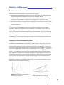
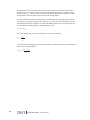
The net torque acting at “center of gravity” is constant for the weight calibration
setup, which makes equation 1 and 2 equal, making it possible to calculate the force
acting on the force transducer:
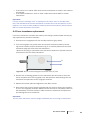
rTA · FT · sinθ2 = rPA · (mweigt · g) · sinθ1
FT = rPA · (mweigt · g) · sinθ1
rTA · sinθ2
As the length of the “pan arm” is 2 cm, the length of the “transducer arm” is 4 cm,
the weight is 2 g, both angles are 900 and the acceleration of gravity is 9.81 ms-2, the
force acting on the force transducer is:
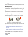
FT = 2cm · (2 g · 9.81 ms-2) · sin90
4 cm · sin90
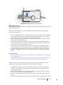
FT = 9.81 gram · m · s-2
As 1 N is equal 1 kg · m · s-2, FW is equal to:
FT = 9.81 mN
Weight calibration procedure
1. Move the pins apart in the myograph chambers. Mount a wire on the transducer
side of the myograph jaws in all chambers*. Place the units on the interface,
plug in the cables, and fill the chambers with double distilled water
*This is not required if the mounting support pins are used instead of the jaws.
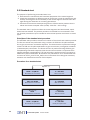
2. Turn on the heating in the Heat main menu of the Myo-Interface. The system will
typically reach the target set temperature (by default, 370C) after ~20 minutes.
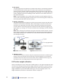
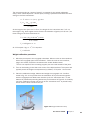
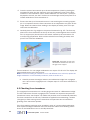
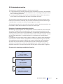
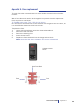
3. Place the calibration bridge, balance and weight on myograph unit 1 as illustrated in fig. 4.6. It is important that the calibration kit is pre-warmed together
with the myograph unit. Make sure that the tip of the “transducer arm” on the
balance is positioned protruding behind the pin illustrated in Figure 4.4. Carefully
move the calibration bridge until the tip of the “transducer arm” is placed freely,
which means it does not touch the pin.
Figure 4.4 Weight calibration setup
User manual 700MO
Chapter 4
21