1
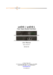
D
i
g
i
g
r
a
m
NCX
User’s Manual
D
i
g
i
g
r
a
m
INFORMATION FOR THE USER
This device complies with part 15 of FCC rules.
Operation is subject to the following two
conditions: (1) This device may not cause harmful
interference, and (2) This device must accept any
interference received, including interference that
may cause undesired operation.
This equipment has been tested and found to comply
with the limits for a CLASS B digital device,
pursuant to Part 15 of the FCC Rules. These limits
are designed to provide reasonable protection
against harmful interference in a residential
installation. This equipment generates, uses, and
can radiate radio frequency energy and, if not
installed and used in accordance with the
instructions contained in this data sheet, may cause
harmful interference to radio and television
communications. However, there is no guarantee
that interference will not occur in a particular
installation.
If this equipment does cause harmful interference to
radio or television reception, which can be
determined by turning the equipment off and on,
the user is encouraged to try to correct the
interference by one or more of the following
measures:
• reorient or relocate the receiving antenna
• increase the separation between the equipment and the
receiver
• connect the equipment into an outlet on a circuit
different from that of the receiver
• consult the dealer or an experienced audio television
technician.
2
NOTE: Connecting this device to peripheral devices
that do not comply with CLASS B requirements or
using an unshielded peripheral data cable could
also result in harmful interference to radio or
television reception. The user is cautioned that any
changes or modifications not expressly approved
by the party responsible for compliance could void
the user’s authority to operate this equipment. To
ensure that the use of this product does not
contribute to interference, it is necessary to use
shielded I/O cables.
IMPORTANT NOTICE
This device has been tested and found to comply with
the following standards :
• International : CISPR22 Class B.
• Europe : EMC 89/336/CEE (1992) specifications.
• United States : FCC Rules-Part 15-Class B (digital
device).
In order to guarantee compliance with the above
standards in an installation, the following must be
done:
• Connectors must have a conductive shell.
• Cables must be shielded and their shield must be
tightly connected to the shell of the connectors.
NCX
User’s Manual
AVAILABLE OPTIONS :
NCX can be delivered with one of the following
options
• NCX 200 : 2 mono outputs
• NCX 400 : 4 balanced mono outputs
• NCX 040 : 4 balanced mono inputs (with mic/line
level selection)
• NCX 220 : 2 mono inputs (with mic/line level
selection) and 2 mono outputs
OVERVIEW
• Independent device exchanging digital sound
through Ethernet 803.3 network
• 10 BASE-T Ethernet interface.
• 2 or 4 analog mono outputs and 1 stereo
headphone output (depending on option).
• 4 analog mono inputs (depending on option).
• 7 general purpose inputs/outputs.
• 2 general purpose RS232 links.
SOFTWARE
REQUIREMENTS
HARDWARE
INSTALLATION
• Install the NCX box in the suitable place,
• Connect the audio input/output,
• Connect the network cable (RJ45)
• Connect the power supply to the NCX box (mini
DIN plug)
• Plug the power supply into the AC supply socket.
SOFTWARE
INSTALLATION
(np DRIVER ONLY)
No driver floppy disk is delivered with the NCX.
Please ask your supplier for an updated driver or
download it from the Digigram Web site.
Make sure that the driver has been approved by your
supplier. Your supplier’s application may request
the use of a specific driver.
Please refer to the installation documentation which is
delivered with the driver. It details the installation
procedure to follow under Windows 95/98 and
Windows NT.
• V99.2 np SDK or higher (no PCX cards managed)
• V5.40 np SDK or higher (PCX cards also
managed)
3
D
i
g
i
g
r
a
m
DETAILED FEATURES
Audio outputs (when available)
Analog outputs
• 2 or 4 balanced analog outputs
(available on SubD15)
• 2 unbalanced analog outputs (on RCA or 3.5mm
stereo jack)
• output impedance < 100 ž.
• maximum level : +10dBu on balanced outputs +4dBu on unbalanced outputs (software
adjustable)
• output level adjustment : down to - 91.5dBu by
0.5dB steps.
• 24 bits digital to analog converters
(128 x oversampling delta-sigma converters).
• Sampling frequencies : 8, 11.025, 16, 22.05, 24,
32, 44.1, 48 kHz
Headphone output
• 3.5mm stereo jack
• Source impedance : 100 ž
Audio inputs (when available)
Analog inputs
• 2 or 4 balanced analog inputs
(available on SubD15)
• output impedance > 10k ž.
• maximum level : +10dBu (line level) or - 26dBu
(mic 1 level) or - 37dBu (mic 2 level)
• 24 bits digital to analog converters (128 x
oversampling delta-sigma converters).
• Sampling frequencies : 8, 11.025, 16, 22.05, 24,
32, 44.1, 48 kHz
Analog performances
4
Characteristics are measured at 48 kHz sampling
frequency, in linear (PCM) mode.
• Signal / Noise ratio (un-weighted) : better than 94
dB.
• Total Harmonic Distortion + Noise (un-weighted):
better than - 85 dB (0.0056%)
with 1kHz signal, -2dBFs.
• Frequency response (20Hz/20kHz) : ± 0.1 dB .
• Difference in phase (20Hz/20kHz) : 0.2° / 2°
• Crosstalk at 1kHz : better than - 95 dB
Physical
• Cabinet dimensions : 175mm x 175mm x 45mm
• The cabinet includes a metallic shell
Power consumption (typical)
• + 5V input : 1.5A
• AC power : 25VA
Environmental
Temperature:
• Storage : -5°C / +70°C
• Operating : 0°C / +50°C
Humidity (non condensing):
• Storage : 0% / 95%
• Operating : 5% / 90%
NCX
User’s Manual
Network
NCX appliance includes a standard Ethernet 10 BASET interface. Wiring of the network must obey to
standard rules.
If more than 2 NCX appliances are connected to the
same sound server, it is mandatory to use a 100
BASE-T Ethernet adapter on the server side and a
10/100 BASE-T hub or preferably a 10/100
BASE-T switch.
Processing
Processing power is given by the internal DSP 56303
associated with a micro-controller managing data
exchange over Ethernet port.
Miscellaneous
General Purpose Interface
• 7 TTL I/O user definable.
Serial Interface
• 2 independent RS232 receiver/transmitter pairs
5
D
i
g
i
g
r
a
m
SCHEMATIC DIAGRAM
XTAL
Depends on selected option
Depends on selected option
CLOCK
GENERATION
ANALOG IN
ADC
DSP
Level setting
RS232 #1
RS232 #2
RS232
CONTROL
Level adjust
LAN
MANAGEMENT
ETHERNET
10BaseT
NOTE : Depending on the selected option, only analog
input or analog output may exist.
6
ANALOG OUT
DAC
PARALLEL
CONTROL
GP OUT
GP IN
NCX
User’s Manual
Front panel
Rear panel
J1
J2
Status LEDs
R : Red : Power ON
G : Green : DSP activity
Y : Yellow : LAN activity
J1 - Parallel I/O connector. (SubD 15 female; front side)
To use this connector, please refer to programming
manual
pin # Signal
pin #
1 GND
9
2 VCC (5V/100mA max.) 10
3 PIO30
11
4 reserved
12
5 #RESET to ext. system
13
6 PIO17
14
7 reserved
15
8 GND
J2 - Serial I/O RS232 connector.
(SubD 9, male; front side)
pin # Signal pin #
1
nc
6
2
RXD1
7
3
TXD1
8
4
nc
9
5
GND
J5
J3
Signal
reserved
PIO31
PIO4
PIO5
PIO2
PIO25
reserved
Signal
nc
nc
RXD0
TXD0
NOTA : TXD1 and RXD1 are standard RS232 TX/RX pins
J3 - Stereo Headphone 3.5mm Jack connector : Stereo
channel #1 output. Delivers the same signal as
outputs OUT1 ( L ) and OUT2 ( R ), with a
headphone adaptor.
J6
J4
J4 - Analog Audio connector.
(SubD 15, female; back side)
pin # NCX 200
2 outputs
1 OUT2 + ( R )
2 GND
3 OUT1 – ( L )
4 GND
5 GND
6 reserved
7 reserved
8 GND
9 OUT2 – ( R )
10 OUT1 + ( L )
11 GND
12 GND
13 reserved
14 GND
15 reserved
NCX 400
4 outputs
OUT2 + ( R1 )
GND
OUT1 – ( L 1)
GND
GND
OUT4 – ( R2 )
OUT3 + ( L2 )
GND
OUT2 – ( R 1)
OUT1 + ( L 1)
GND
GND
OUT4 + ( R2 )
GND
OUT3 – (L 2)
NCX 040
4 inputs
IN4 + ( R 2)
GND
IN3 – ( L2 )
GND
GND
IN2 – ( R1 )
IN1 + (L1)
GND
IN4 – ( R 2)
IN3 + ( L2)
GND
GND
IN2 + ( L1 )
GND
IN1 – ( R1 )
NCX 220
2 ins – 2 outs
OUT2 + ( R )
GND
OUT1 – ( L )
GND
GND
IN2 – ( R )
IN1 + (L)
GND
OUT2 – ( R )
OUT1 + ( L )
GND
GND
IN2 + ( L )
GND
IN1 – ( R )
J5, J6 - RCA (Phono) Plugs
Stereo output #1, delivers the same signal as outputs
OUT1 ( L ) and OUT2 ( R ), but in unbalanced mode.
Available options
•
•
•
•
Analog breakout cable for NCX200
Analog breakout cable for NCX400
Analog breakout cable for NCX040
Analog breakout cable for NCX220
7
Digigram S.A France
E-mail : [email protected]
Digigram Inc. USA
E-mail : [email protected]
Digigram Asia Pte Ltd
E-mail : [email protected]
www.digigram.com