1
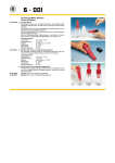
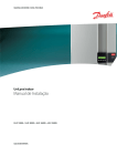
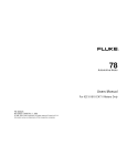
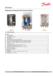
User Manual
Infratherm Pyrometer
IN 5 · IN 5/5
Contika
Hindhøjen 82
8382 Hinnerup
www.contika.dk
Contents
1. Scope of delivery.......................................................................................................................18
2. Equipment directory Infratherm IN 5; IN 5/5.............................................................................18
3. Optics ........................................................................................................................................19
4. Technology................................................................................................................................20
4.1. Technical description...........................................................................................................20
4.2. Technical data.....................................................................................................................21
5. Instrument settings...................................................................................................................22
5.1. Controls...............................................................................................................................22
5.2. Emissivity (EMI)...................................................................................................................22
5.2.1. Explanation.............................................................................................................22
5.2.2. Emissivities of common materials............................................................................23
5.2.3. Set up examples for IN 5; IN 5/5.............................................................................23
5.3. Response time t90 ................................................................................................................23
6. Electrical installation ................................................................................................................24
6.1. Connector assignment.........................................................................................................24
6.2. Display devices ...................................................................................................................24
6.3. Connection schematic for display devices............................................................................24
6.4. Examples for the IN 5 with peripheral devices......................................................................25
7. Mechanical installation .............................................................................................................25
7.1. Davice dimensions IN 5; IN 5/5...........................................................................................25
7.2. Adjustable mounting support with 2 axes .............................................................................26
7.3. Water cooling jacket / Air purge ...........................................................................................26
7.4. Water cooling jacket (heavy duty) with integrated air purge ..................................................27
7.5. Mounting tube .....................................................................................................................27
7.6. Flange tube .........................................................................................................................27
7.7. Vacuum flange ....................................................................................................................28
7.8. Avoiding reading errors caused by faulty assembly..............................................................28
8. Order numbers for IN 5 und IN 5/5 instruments incl. optics....................................................28
8.1. Ordering example for IN 5....................................................................................................38
8.2. Accessories.........................................................................................................................39
8.2.1. Mechanical accessories ..........................................................................................39
8.2.2. Electrical accessories..............................................................................................39
9. Further information...................................................................................................................30
9.1. Maintenance........................................................................................................................30
9.2. Packing instructions.............................................................................................................30
9.3. Warranty .............................................................................................................................30
9.4. Limit of Liability....................................................................................................................30
9.5. Copyright.............................................................................................................................30
10. Glossary ....................................................................................................................................31
11. Subject index ............................................................................................................................33
17
Congratulations on choosing the IMPAC pyrometer. You are now the owner of a
compact infrared non-contact thermometer, which combines efficiency and excellence for optimal temperature measurements.
Please read this manual carefully before installing this pyrometer. It contains all the
necessary information to set up and operate the new IMPAC pyrometer.
Should you require further assistance, please call our customer service hotline in
Germany (+49) (0) 69 9 73 73-190.
IMPAC has been developing and manufacturing non-contact temperature measurement instruments since 1958 and has more than 60 000 pyrometers and systems installed worldwide.
IMPAC Electronic GmbH
1. Scope of delivery
− Pyrometer with optics (IN 5: a = 100, 300 or 800 mm. IN 5/5: a = 100, 300 or 1200 mm)
Please Note:
A connecting cable is not included with the instrument and should be
ordered separately (see 8. Order numbers).
2. Special features Infratherm IN 5; IN 5/5
− Suitable for measuring objects with non-metallic surfaces (IN 5) and metals which are painted or oxidised or glass surfaces (IN 5/5)
− Measures temperature ranges between -32 and 900 °C (IN 5); between 100 and 2500 °C (IN 5/5)
− Two wire technique
− Analog output 4 - 20 mA
− Digital linearization guarantees accuracy up to 0.6 % of the measured value
− Readings are unaffected by the relative humidity or the amount of CO2 in the air
− Stainless steel housing
− Adjustable emissivity from 0.20 to 1.00 (20 - 100 %) in 0.01 (1 %) steps
− Adjustable response time from 0.08 to 5 sec
Safety warning:
Caution!
Do not clean the lens with liquids containing acids or solvents
18
3. Optics
The pyrometer is available with various optical profiles. Select the optics that are most appropriate for your
application from the optical profiles shown below. The optics must be chosen when ordering the instrument,
and cannot be changed once installed.
A pyrometer operates passively. It receives heat radiation, from the measured object, which passes through
the lens and is then converted to an electrical signal. The measured object may be at any distance from the
pyrometer! However, the farther the measured object is from the pyrometer, the larger the area (spot size)
that will be measured by the pyrometer. The object (or the area on the object) that you want to measure has
to be as big (or bigger) than the pyrometer's spot size, for that distance.
The following drawings show the pyrometer's spot sizes (minimum required sizes for the measured object)
and the focal distances, in relation to the distance from the pyrometer. The spot size at a distance of 0 mm
(a = 0) is 15 mm (M = 15) or 10 mm (M = 10 at the IN5/5, MB 25), which is the diameter of the aperture
behind the lens.
Distance a [mm]
0
200
100
300
IN 5; Optics 100
Spot size M [mm]
Distance a [mm]
2
15
0
300
15
6
18
600
35
1000
IN 5; Optics 300
Spot size M [mm]
22
45
2500
Distance a [mm]
0
800
15
16
1500
IN 5; Optics 800
Spot size M [mm]
36
68
Distance a [mm]
0
100
200
300
IN 5/5; Optics 100
Spot size M [mm]
Distance a [mm]
2,5
15 (10)*
300
0
18 (13)*
35 (24)*
1000
600
IN 5/5; Optics 300
Spot size M [mm]
Distance a [mm]
15 (10)*
6
1200
0
22 (17)*
2500
45 (32)*
4000
IN 5/5; Optics 1200
Spot size M [mm]
15 (10)*
24
50 (43)*
80 (65)*
* MB 25 at the IN 5/5
Note:
Please note that the optical profiles show nominal dimensions. The spot size diameter
or the focal distance may be slightly different due to lens tolerances.
19
The optical profiles show that the spot size M varies with the distance from the pyrometer.
Spot sizes for intermediate distances, that are not shown on the optical profiles, may be calculated using the
following formula, where:
D = 15 mm (10 mm at IN 5/5, MB 25) (the aperture diameter)
a = the nominal distance (from the optical profiles )
M = the nominal spot size (from the optical profiles)
M2 =
a2
(M − D )+ D
a
M1 =
a1
(M + D )− D
a
a1
a
a
2
Ø M2
Ø M1
ØM
ØD
4. Technology
4.1. Technical description
All objects whose temperature are above absolute zero (-273.15 ºC / -459.67 ºF) emit heat. Most of this heat
is emitted as infrared (IR) radiation.
IMPAC pyrometers are measuring instruments, which receive heat radiation through the optics and focus it
on a detector. The detector converts it into an electric signal. This signal is digitally linearized and converted
into a standard analog output signal.
For best accuracy, the correct optical filter with the appropriate spectral range must be selected for the the
type of material that is being measured. For example, select the IN 5 with the 8 to 14 µm spectral range for
measuring non-metallic surfaces or the IN 5/5 with the narrow 5.14 µm nominal bandwidth for measuring
glass surfaces.
An integrated micro-controller performs all calculations and digital processing.
20
4.2. Technical data
Temperature ranges:
IN 5:
0 to 100 °C
0 to 200 °C
0 to 300 °C
0 to 400 °C
0 to 500 °C
0 to 900 °C
- 32 to + 50 °C
IN 5/5: 100 to 600 °C
200 to 800 °C
100 to 1300 °C
400 to 2500 °C
(custom temperature ranges for either instrument are available on request)
Data handling:
Digital
Spectral response:
IN 5:
IN 5/5:
8 to 14 µm
5.14 µm
(for all general applications on non-metallic surfaces and metals which are painted or oxidised)
(narrow band, for glass surfaces)
Optics:
IN 5: Germanium (Ge) Lens
IN 5/5: Zinc Sulfide (ZnS) Lens
IR-detector:
Silicon (Si)-based thermopile
Power supply:
24 V DC (10 to 30V) ripple must be less than 0.5 V
Analog output:
4 - 20 mA, direct current, linear
resolution: 2880 steps
Load:
max. 700 Ω at 24 V (max. 100 Ω at 12 V)
Emissivity:
user-adjustable from 0.20 - 1.00 in steps of 0.01
Response time t90:
user-adjustable from 0.08 to 5 sec
Accuracy:
IN 5
Tu
15 to 30 °C
0 to 15 °C or
Dependent on object temperaT
30 to 63 °C
ture T and ambient tempera0 to 300 °C 0.6 % of measured value 1 % of measured value in
ture Tu
)
)
in °C or 1 °C ∗
°C or 1.5 °C ∗
(ε = 1, t90 = 1 sec):
300 to 900 °C 1 % of measured value 1.3 % of measured value
in °C
in °C
-32 to 0 °C
1.5 °C
2 °C
IN 5/5
Tu
15 to 30 °C
0 to 15 °C or
T
30 to 63 °C
100 to 1300°C 0.6 % of measured value 1 % of measured value in
)
)
in °C or 2 °C ∗
°C or 3 °C ∗
1300 to 1800°C 0.8 % of measured value 1.2 % of measured value
in °C
in °C
1800 to 2500°C 1 % of measured value 1.4 % of measured value
in °C
in °C
∗)
whichever value is greater. The instrument must be at a constant ambient temperature for a minimum of 15 minutes
21
Repeatability:
IN 5; IN 5/5:
∗)
0.3 % of measured value in °C or 0.6 °C ∗
)
whichever value is greater. The instrument must be at a constant ambient
temperature for a minimum of 15 minutes
Noise Equivalent Temperature 0.2 K (σ = 1) measured temperature = 23 °C, t90 = 80 ms and ε = 1
Difference (NETD):
0.05 K (σ = 1) measured temperature = 23 °C, t90 = 1 sec and ε = 1
Ambient temperature:
0 to +70 °C (IN 5/5, MB 25: 0 to 63 °C)
Storage temperature:
-20 to +70 °C
Enclosure rating:
IP 65 (DIN 40050)
Weight:
400 g
Dimensions:
111 mm x 49,5 mm (l x d)
Housing:
Stainless steel
Operating position:
Any
CE Approval / EMV tests:
Satisfies EU regulations for electromagnetic immunity (industry norm)
5. Instrument settings
5.1. Controls
The controls are located under the rear cover of the pyrometer and can be
accessed by removing the rear cover. To remove the rear cover unscrew
both rear screws and take the cover off, making sure it remains straight
(without bending or twisting it).
Caution:
Disconnect the cable before opening the
cover. Reconnect only when assembly is complete!
When reassembling the cover, insert it carefully into the guide pins and then
fasten it with the screws. The connector cable can now be plugged in.
5.2. Emissivity (EMI)
5.2.1. Explanation
The temperature of a given object can only be measured correctly if its exact emissivity ε (Epsilon) is known
and the pyrometer is set up accordingly. The emissivity is the ratio between the level of radiation from an
object and the level of radiation from a black body radiator at the same temperature. Different materials have
different emissivities ranging between 0 and 1.00 (or 0% and 100% ).
A value of ε = 1 means that the material absorbs all incoming radiation acting like a black body (a perfect
absorber and perfect emitter). Materials which reflect more radiation have a lower emissivity and the emissivity control of the pyrometer needs to be adjusted accordingly. Emissivity values of common materials are
listed in table 5.2.2. Emissivities of common materials.
Note:
The minimum emissivity setting for the pyrometer is 0.20 (20 %)!
One way to determine an accurate emissivity value for a material is to make a comparison measurement.
This can be done as follows:
22
1. Measure the surface temperature of the object using a contact thermometer (e.g. Tastotherm MP2000 with
a suitable probe) and, at the same time, measure the temperature using the pyrometer. Adjust the
emissivity control until the pyrometer displays the same temperature as the thermometer.
2. If possible, coat a portion of the object with dull black paint or carbon soot. Paint and carbon soot have
high emissivities (0.95) and take on the same temperature as the object. Measure the temperature of the
painted area with the emissivity control set to 95 %. Then measure the temperature of an adjacent unpainted area of the object and adjust the emissivity until the pyrometer displays the same temperature.
5.2.2. Emissivities of common materials
Object
ε (at 8 to 14 µm)
Object
"Black body furnace"
Human skin
Black dull varnish
Carbon soot
Wood
Paper
Asphalt
Glass/Quartz glass
Textile
Graphite
Cement
Water
1.00
0.98
0.95
0.95
0.8 - 0.92
0.92 - 0.95
0.85
0.72 - 0.87
0.75 - 0.95
0.75 - 0.92
0.9
0.95
Brickwork
Fire clay
Rubber
Porcelain
Ceramics
Varnish
Plaster
Oil paint
Steel (oxidized)
Steel (smooth)
Aluminium (smooth)
Aluminium (anodized)
Object
ε (at 5.14 µm)
Glass/Quartz glass
0.97
ε (at 8 to 14 µm)
0.85 - 0.95
0.6 - 0.8
0.1 - 0.3
0.02 - 0.15
0.9
5.2.3. Set up examples for IN 5; IN 5/5
ε = 1.00
Adjust both switches (EMI) as shown in the example
on the left.
ε = 0.85
Emissivity ε can be adjusted between
0.20 and 1.00 in steps of 0.01.
Note:
If the emissivity is set to a value below 0.2 the instrument will automatically utilize an
emissivity value of 1. The setting 00 is interpreted as ε = 1.00!
5.3. Response time t90
The response time t90 is the time interval from the
start of measurement up to the respective change in
the output signal (4 - 20 mA) which is the time taken
to reach 90 % of the recorded temperature difference.
The response time is changed by adjusting the
jumper position. In the open position shown in the
diagram on the left, the response time is 0,08 s.
For alternative settings (t90 = 0,5 s, 1 s, 2 s or 5 s)
select the respective jumper position (see diagram on
Example: t90 = 0,5 s
Example: t90 = 0,08 s
the right).
Longer response times are useful when measuring objects with fluctuating temperatures.
Settings at delivery:
ε = 1; t90 = 0.08 s
23
6. Electrical installation
The Infratherm IN 5 and IN 5/5 is powered by 24 V DC (10 to 30 V DC). When connecting the device to the
power supply ensure correct polarity. The power consumption (in this case 4 - 20 mA) is also the measuring
signal.
To meet the electromagnetic requirements (EMV), a shielded connecting cable must be used. The shield of
the two wire connecting cable is usually only connected on the pyrometer side. If the connecting cable is
extended, the extension cable also needs to be shielded. Do not connect the shield to the power source side
(control cabinet), to avoid ground loops.
6.1. Connector assignment
Pyrometer plug (connector):
3 pole Flange plug
2
1
3
Pin 1
(white)
+24 V (10 V to 30 V)
Pin 2
(brown)
0V
Pin 3
(black)
shield
6.2. Display devices
To display the temperature, IMPAC offers display devices with
integrated power supplies for two-wire pyrometers as accessories. (see 8. Order numbers)
•
•
•
(DA 4000-N): display only
(DA 4000): DA 4000-N with 2 limit switches
(DA 6000): With 2 limit switches, maximum value storage
and R S232 or RS 485 interface
display device type DA 4000
6.3. Connection schematic for display devices
The DA 4000, DA 4000-N and DA 6000 LED display devices have an integrated 24 V power supply for twowire instruments. If an RS 232 interface is required then the DA 6000 display must be used.
230 V ~
+
+ white
IN 5
– brown
LED-digital display with
integrated power supply
recorder
4 ... 20 mA
-+
controller
+
24
6.3.1. Examples of the IN 5 with peripheral devices
24 V DC
+
-
+ wt
IN 5
- br
+
230 V ~
PL C
-
+
+ wt
IN 5
- br
+
PL C
IN 5
– brown
+ wt
IN 5
- br
+ white
DIN rail power supply
- 24 V DC
-
-
+
+
Separate current output
(e.g. to a computer)
Galvanic separator
+
PL C
-
Note:
Additional instruments with current input e.g. a recorder (see 8. Order numbers) or a
controller can be connected to the display in series as shown above.
7. Mechanical installation
7.1. Device dimensions IN 5; IN 5/5
7
24.5
104.5
6.5
Robust mounting accessories for installation of the Infratherm IN 5 or IN 5/5 are described and depicted in
the following section, along with the article numbers (see also 8.2.1. Mechanical accessories).
25
7.2.
Adjustable mounting
support with 2 axes
Pyrometer
The standard mounting support
is made from stainless steel. It
can be independently adjusted
in the horizontal or vertical
directions (± 45º).
Note: This mounting support
cannot be used with the water
cooling jacket.
Mounting
support
7.3. Water cooling jacket (standard) / Air purge
The standard water cooling jacket
is designed to protect the pyrometer in hot environments with
ambient temperatures above
70 °C (or 63 °C at the IN 5/5, MB
25). With this cooling jacket, the
pyrometer may be operated at
ambient temperatures up to
170 °C when using a cooling
water temperature of 17 °C and a
cooling water flow rate of 0.4
l/min.
The air purge protects the lens of
the pyrometer against dust, humidity and other suspended
matters by blowing air away from
the lens in a cone-shaped air
stream.
Wall
Mounting flange
Connecting flange (or mounting angle)
Rear wall (optional)
Water cooling jacket
Air purge
(or mounting socket)
Note: Both parts are also available separately!
Mounting instructions: Depending on intended use, additional parts may necessary for proper
mounting:
• The water cooling jacket requires an attachment device such as:
- a mounting flange with air purge or mounting socket (not in drawing) and connecting flange.
- or a mounting angle with air purge or mounting socket. (The air purge can also be used
alone in connection with the pyrometer.)
• The mounting flange can be used instead of the connecting flange (or mounting angle); the
mounting angle can also be used instead of the mounting flange.
• The rear cover (with cable duct) serves as an additional temperature protection.
26
7.4. Water cooling jacket
(heavy duty) with
integrated air purge
Air
8 mm
The heavy duty water cooling
jacket protects the pyrometer in
extremely hot ambient temperatures. It is completely closed and
is equipped with a long air purge
tube to protect the lens. With the
heavy duty cooling jacket, the
pyrometer may be operated at
ambient temperatures up to 280
°C when using a cooling water
temperature of 14 °C and a cooling water flow rate of 2 l/min. Max.
water pressure is 6 bar.
Note:
Water
8 mm
Mounting wall
Water
8 mm
The maximum possible ambient temperature is dependant on the temperature and flow
rate of the cooling water. All maximum temperatures stated are for reference and need
to be verified according to the specific conditions. Ensure that the cooling water is at the
correct temperature at all times. If the cooling water is too cold, condensation can build
up inside the device, which will prevent proper functioning of the pyrometer. When using
the pyrometer in very low ambient temperatures, proper operation can be achieved by
using heated throughput water.
Note on air purge: The required airflow rate is approximately 25 - 30 l/min (1.5 - 1.8 m³/h) at
approx. 0.2 - 0.5 bar. Please use clean, dry air (oil and dust free) only!
7.5. Mounting tube
The mounting tube protects the
lens of the pyrometer from dirt.
There is also an 8 mm diameter
connector.
plastic protection cap
Air connector 8 mm
7.6. Flange tube
The flange tube is a
mounting tube with a
weldable flange.
plastic protection cap
Air connector 8 mm
Note on mounting tube:
The air volume required for the mounting tube is approximately
50 - 60 l/min (3.0 - 3.6 m³/h) at approx. 0.4 - 1 bar.
27
7.7. Vacuum flange
The vacuum flange separates the
pyrometer from the process area.
The pyrometer can be easily
removed, without an interruption
to the process (furnace or vacuum).
The decrease in radiation, due to
the window’s transmission, can be
compensated by reducing the
emissivity setting by the appropriate factor.
Window material:
KF16
Vacuum flange KF 16
Pyrometer
Fenster
•
IN5:
ZnSe
Transmission:
71 %
•
IN 5/5:
CaF2
Transmission:
94 %
7.8. Avoiding reading errors caused by faulty assembly
To avoid reading errors, please note the following points when mounting the pyrometer:
1. The diameter of the measuring object cannot be smaller than the pyrometer’s spot size (see 3. Optics).
2. A source of radiation behind or around the measuring object can influence the result. If the object is
transparent or partly transparent another material behind the object could transmit its radiation to the pyrometer as well. In this case the location of the pyrometer should be changed, or, if the background radiation remains constant it can be compensated for by changing the emissivity setting respectively.
3. Please take into account that radiation from other hot parts around the measured object can be reflected
by it and influence the result. If the measured object has a low emissivity, the temperature measured will
be mainly that of the reflected object not from the intended measured object itself. To prevent environmental radiation from reaching the spot area, a mounting tube should be used. The mounting tube
should be placed as near as possible to the measured object so that the tube’s shadow blocks out all the
environmental radiation.
8. Order numbers for IN 5 or IN 5/5 instruments incl. optics
Order numbers IN 5
8 to 14 µm
3 869 010
3 869 020
3 869 030
3 869 040
3 869 050
3 869 090
3 869 100
Messbereich
0 to 100 °C
0 to 200 °C
0 to 300 °C
0 to 400 °C
0 to 500 °C
0 to 900 °C
- 32 to + 50 °C
Order numbers IN 5/5
5.14 µm
3 869 110
3 869 120
3 869 130
3 869 140
Messbereich
100 to 600 °C
200 to 800 °C
100 to 1300 °C
400 to 2500 °C
Custom ranges available upon on request.
The optics must be specified when ordering
IN 5: a = 100, 300 or 800 mm;
IN 5/5: a = 100, 300 or 1200 mm
Note:
The length of the measuring area does not affect the accuracy of the pyrometer, but does
affect the resolution of the analog output (2880 steps for the range 4 - 20 mA).
8.1. Ordering example for IN 5
3 869 040
3 820 560
28
IN 5, Temperature range 0 to 400 °C
Optics a = 300 mm
Connecting cable 5 m length
8.2. Accessories
8.2.1. Mechanical accessories:
Order No.:
Accessory:
3 834 210
Mounting bracket (adjustable)
3 835 160
Air purge
Water cooling system (combination):
3 837 080
Standard water cooling jacket for ambient temperatures up to 170 °C
3 846 100
Mounting tube
3 835 080
Mounting angle
3 835 070
Connecting flange
3 835 160
Air purge
3 835 090
mounting socket
3 835 110
Rear wall for cooling jacket
3 837 230
3 846 120
3 846 620
3 846 630
3 846 650
3 846 660
Water cooling jacket (heavy duty) with integrated air purge for ambient temperatures up
to 280 °C
Flange tube
Vacuum flange KF16 with CaF2–window for IN 5/5
Vacuum flange KF16 with ZnSe-window for IN 5
Spare window CaF2 Ø 25x3 with Viton-O-ring
Spare window ZnSe Ø 25x3 with Viton-O-ring
8.2.2. Electrical Accessories:
Order No.:
3 820 210
3 820 560
3 820 570
3 820 580
3 820 590
3 820 280
3 890 600
3 890 960
3 890 610
3 890 640
3 890 650
3 890 520
3 890 530
3 890 660
3 863 010
Accessory:
Connection cable 2 m long
Connection cable 5 m long
Connection cable 10 m long
Connection cable 15 m long
Connection cable 30 m long
Connection cable 2 m long, temperature resistant up to 200 °C, (Silicone)
Power supply for DIN rail mounting (230 V AC into 24 V DC)
Power supply for DIN rail mounting (115 V AC into 24 V DC)
Galvanic separator for DIN rail mounting (no extra power supply necessary)
DA 4000-N: LED-Digital display with integrated 2 wire supply
DA 4000: like DA 4000-N, but additionally with 2 limit switches
DA 6000: analog input and 2 limit switches, RS 232-interface
DA 6000: analog input and 2 limit switches, RS 485-interface
IP 65-front cover for LED digital display
Converter IW 5-C (4 - 20 mA into 0 - 20 mA)
29
9. Further information
9.1. Maintenance
The pyrometer has no internal parts which have to be cleaned. The lens can be cleaned with compressed air
which is dry and free of oil. If the lens requires more thorough cleaning, use a soft, dry cloth such as that
used to clean camera objectives.
Caution: Do not clean or touch the lens with acidic or solvent liquids!
The Ge lens of the IN 5 has an anti-reflective coating which appears slightly colored.
Be extremely careful - this layer can easily be rubbed off - this will greatly affect the measuring results!
9.2. Packing instructions
To transport or store the instrument, please use the original box or a box padded with sufficient shockabsorbing material. For storage in humid areas or shipment overseas, the device should be placed in welded
foil (ideally along with silicon gel) to protect it from humidity .
9.3. Warranty
All series 5 instruments from IMPAC Electronic GmbH have a warranty of two years from the invoice date.
This warranty covers manufacturing defects and faults which arise during operation only if they are the result
of defects caused by IMPAC Electronic GmbH. User-induced faults are not covered with this warranty.
9.4 Limit of Liability
IMPAC Electronic GmbH is not liable for any damages that arise from the use of any examples or processes
mentioned in this manual.
9.4. Copyright
All copyrights reserved. This document may not be copied or published, in part or whole, without the prior
written permission of IMPAC Electronic GmbH.
30
10. Glossary
Absolute zero
-273.15°C (-459.67 ºF), lowest possible natural temperature. No molecular activity occurs.
Absorption
Transfer of energy to a material by means of wave radiation or particle radiation.
Reception of energy (light, heat), gases or liquids.
Air purge
Accessory to keep dust and dirt away from the optics
Aperture
Optical diameter of the stop of an objective
Black body
A body that absorbs all incoming radiation at all wavelengths and that emits the
maximum possible radiation at all wavelengths for its temperature (has an emissivity value of 1 at all wavelengths)
Black body furnace
Radiates almost like an ideal black body. Needed for calibrating and testing
infrared pyrometers
Calibration
Comparison of the pyrometer to international temperature standards and adjustment so that it measures accurately in accordance to the temperature standards
Certificate
Document on the conformity of the calibration accuracy
Contact thermometer
Temperature measuring device which measures an object’s temperature by
contact, for example thermocouples or resistance thermometers
Cooling jacket
Accessory for using the pyrometer at high ambient temperatures
Detector
Receptor for radiation. Changes heat radiation into an electrical signal
Emissivity
Ratio of the radiation emitted by a surface to that emitted by a black body at the
same temperature
Infrared (IR)
Electromagnetic waves that are invisible and have longer wavelengths than red
light in the visible spectrum. Wavelengths between 0.78 and 1000 µm.
Instrument temperature Automatic compensation for the temperature change of the pyrometer due to a
compensation
change in the ambient temperature
Interface
RS 232, RS 485, digital output for communication between pyrometer and computer or bus
Lens tolerance
Production-determined spread of focal length and centering
Limit switches
Relays that switch at predefined temperatures. i.e. high/low alarm ( located in the
power supply or digital display )
Linearization
A function of the signal processing performed by the microprocessor in a pyrometer. Establishes the proportionality between the measured temperature and the
output signal
Maximum measuring
range limit
Upper limit of the measuring range (highest measurable temperature
for the pyrometer)
31
Minimum measuring
range limit
Lower limit of the measuring range (lowest measurable temperature
for the pyrometer)
Measuring distance
Distance between the measured object and the lens of the pyrometer
Measuring uncertainty
Most probable deviation between displayed and true temperature
Objective
Optical system which consists of lenses or mirrors and which forms the object’s
image on the detector of the pyrometer
Pyrometer
Instrument for non-contact temperature measurement (radiation thermometer)
Rate of reflection
Ratio of reflected intensity to incident intensity
Reflection
Return of radiation rays at the border between two materials, may be directed or
diffuse
Repeatability
The uncertainty with which a measured value may be reproduced under constant
conditions (same instrument, same environmental conditions)
Soot
black carbon in powder form (residue of incomplete burning of organic substances) has very high emissivity
Spectral range
The wavelength range within the electromagnetic spectrum used by the pyrometer
Spectrometer
Measuring device which determines the radiation intensity in relation to the wavelength
Spot size
Area on the object from which the pyrometer receives the temperature radiation
Temperature
Corresponds to the average molecular velocity inside the material, measured in
Kelvin, °Celsius or °Fahrenheit
K = °C + 273.15
°C = 0.555 (°F - 32)
°F = 1.8 °C + 32
Test certificate
Certificate stating the accuracy of a measuring device in relation to known standards
Wavelength
Property of electromagnetic waves, corresponding to the color of light for the
visible part of the electromagnetic radiation
Window
Special glass plate, for protection of the pyrometer against hazardous materials,
which allows the pyrometer to measure a process (through the window)
32
11. Subject index
A______________________________________
Accessories .................................................... 29
Accuracy ........................................................ 21
Air connector...............................................26/27
Air flow rate .................................................... 27
Air purge ....................................................26/27
Ambient temperature ..................................26/27
Aperture.......................................................... 19
Assembly, faulty ............................................. 28
B______________________________________
Black body radiator ......................................... 22
C______________________________________
Connecting cable ........................................18/22
Connecting flange .......................................... 26
Connection examples...................................... 25
Connection for display devices ........................ 24
Connection schematic ..................................... 24
Connector assignment .................................... 24
Contact thermometer ...................................... 23
Controls .......................................................... 22
Cooling jacket ............................................26/27
Copyright ........................................................ 30
D______________________________________
DA 4000/DA 6000 ........................................... 24
Dimensions .................................................... 25
Direct current ................................................. 24
Display devices ............................................... 24
Distance ......................................................... 19
E______________________________________
Electrical accessories...................................... 29
Electrical installation........................................ 24
Emissivities of common materials.................... 23
Emissivity........................................................ 22
Equipment directory ........................................ 18
Explanation ..................................................... 22
F______________________________________
Faulty assembly .............................................. 28
Flange tube .................................................... 28
Further Information.......................................... 30
G______________________________________
Glossary......................................................13/32
L______________________________________
Lens tolerances............................................... 19
Lens................................................................ 30
Limit of Liability................................................ 30
M______________________________________
Maintenance ................................................... 30
Materials ......................................................... 23
Mechanical accessories .................................. 29
Mechanical installation .................................... 25
Mounting support ............................................ 26
Mounting tube ................................................ 27
O______________________________________
Optics.............................................................. 19
Order numbers ............................................... 29
Ordering example ........................................... 28
P______________________________________
Packing instructions......................................... 30
Polarity............................................................ 24
Power consumption......................................... 24
R______________________________________
Reading errors ................................................ 28
Response time ............................................... 23
S______________________________________
Safety warning ............................................... 18
Scope of delivery ............................................ 18
Set up examples.............................................. 23
Settings at delivery .......................................... 23
Shielding ......................................................... 24
Signal ............................................................. 24
Spot size ........................................................ 19
Switches ......................................................... 23
Switches ......................................................... 23
T______________________________________
Technical data............................................ 21/22
Technology .................................................... 20
Transmission................................................... 28
Two wire principle ........................................... 24
V______________________________________
Vacuum flange ................................................ 29
W______________________________________
Warranty ........................................................ 30
Water cooling jacket ................................... 26/27
Wavelength .................................................... 20
33
IMPAC Electronic GmbH
Temperaturmessgeräte
Krifteler Str. 32
D - 60326 Frankfurt/Main
Tel.: +49-(0)69-9 73 73-0
Fax: +49-(0)69-9 73 73-167
Internet: www.ir-impac.com
E-Mail: [email protected]
3 869 018-B