1
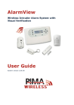
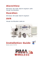
AlarmView
Wireless Intruder Alarm System with
Visual Verification
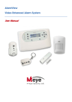
Guardian
Wireless Intruder Alarm System
AVR
Visual Verification Add-on
Installation Guide
System version 2.09.XX
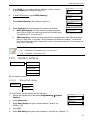
Table of contents
Table of contents
1
Introduction ........................................................................................... 5
2
Quick Reference Guide ......................................................................... 10
3
System Installation .............................................................................. 14
4
Setup and Programming ...................................................................... 23
5
Options menu....................................................................................... 25
6
Event Log menu ................................................................................... 26
7
Service menu ....................................................................................... 27
8
Passwords Menu .................................................................................. 31
9
Set Clock menu .................................................................................... 32
10
Programming menu ............................................................................. 33
1.1
1.1.1
1.2
1.3
1.4
2.1
2.2
2.2.1
2.2.2
2.2.3
2.2.4
2.2.5
3.1
3.2
3.3
3.4
3.4.1
3.4.2
3.4.3
3.4.4
3.5
4.1
4.2
4.3
4.3.1
5.1
5.2
5.3
6.1
7.1
7.1.1
7.1.2
7.1.3
7.1.4
7.1.5
7.2
7.3
8.1
8.1.1
9.1
9.2
Features ..................................................................................................... 5
The AlarmView system ............................................................................... 5
The Guardian system .................................................................................... 6
The AVR Visual Add-on ................................................................................. 7
Technical specifications ................................................................................. 8
System components ...................................................................................
The Control Panel .......................................................................................
The buttons ............................................................................................
The display .............................................................................................
Sound indications ....................................................................................
LED indications .......................................................................................
The INFO screen......................................................................................
General guidelines......................................................................................
Quick installation .......................................................................................
Professional mounting.................................................................................
Other installation options ............................................................................
Standalone wired siren .............................................................................
How to use the trigger inputs ....................................................................
The AVR .................................................................................................
External antenna .....................................................................................
How to confirm system installation ...............................................................
The Installer’s menu map ............................................................................
Accessing the menus ..................................................................................
The Master and Installer passwords ..............................................................
How to reset the passwords to factory defaults ............................................
10
10
11
12
12
13
13
14
14
16
20
20
20
21
22
22
23
24
24
24
Global Settings .......................................................................................... 25
Zone bypass.............................................................................................. 25
Contacts ................................................................................................... 25
Log entry examples .................................................................................... 26
Tests........................................................................................................
Zones ....................................................................................................
External Siren .........................................................................................
Built-in siren ...........................................................................................
Communication .......................................................................................
System self-test ......................................................................................
Display version ..........................................................................................
System reset .............................................................................................
27
27
28
29
29
29
30
30
Installer.................................................................................................... 31
Access mode........................................................................................... 31
Time ........................................................................................................ 32
Date ........................................................................................................ 32
1
Wireless Alarm Systems Installation Guide
10.1
10.1.1
10.1.2
10.1.3
10.1.4
10.1.5
10.1.6
10.2
10.2.1
10.2.2
10.3
10.4
10.5
10.5.1
10.5.2
10.5.3
10.5.4
10.5.5
10.6
10.6.1
10.6.2
10.6.3
10.6.4
10.7
10.8
Zones/Peripherals ......................................................................................
Zones ....................................................................................................
Visual zones (AlarmView and AVR only) ......................................................
Keyfobs/keypads .....................................................................................
Panic button ...........................................................................................
External siren .........................................................................................
Built-in siren ...........................................................................................
Contacts ...................................................................................................
System name .........................................................................................
Contact 1-6 ............................................................................................
CMS contacts ............................................................................................
Communication..........................................................................................
System options ..........................................................................................
Entry/Exit delay ......................................................................................
Arm/Disarm ............................................................................................
PGM output ............................................................................................
Trigger inputs .........................................................................................
Remote access ........................................................................................
Factory defaults .........................................................................................
Return to defaults....................................................................................
Clear Passwords ......................................................................................
Clear zones ............................................................................................
Initialize all.............................................................................................
Local programming ....................................................................................
Firmware upgrade ......................................................................................
33
33
34
35
36
36
37
37
37
37
38
40
41
41
42
43
43
44
44
45
45
45
46
46
46
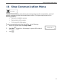
11
Stop Communication Menu ................................................................... 47
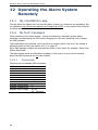
12
Operating the Alarm System Remotely ................................................ 48
12.1 By smartphone app .................................................................................... 48
12.2 By text messages....................................................................................... 48
12.2.1 Commands ............................................................................................. 48
2
Table of contents
Appendixes
Appendix A
System Peripherals ............................................................... 49
Appendix B
The SmartView Detector/ Camera ......................................... 50
Appendix C
The OutView Camera ............................................................. 51
Appendix D
External Siren Indications ..................................................... 53
Appendix E
Maintenance & Troubleshooting ............................................ 54
Appendix F
Glossary of terms .................................................................. 55
Appendix G
Event Reporting .................................................................... 57
Appendix H
SIA and ContactID Codes ...................................................... 59
Appendix I
SMS confirmation messages .................................................. 60
Appendix J
Limited Warranty .................................................................. 61
Appendix K
Declaration of Conformity ..................................................... 62
B.1
B.2
C.1
C.2
E.1
E.2
E.3
H.1
H.2
H.3
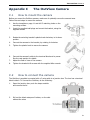
How to mount the detector .......................................................................... 50
How to replace the battery .......................................................................... 50
How to mount the camera ........................................................................... 51
How to connect the camera ......................................................................... 51
Cleaning the LCD screen ............................................................................. 54
Replacing the Control Panel’s battery ............................................................ 54
SIM card icons and LED behavior .................................................................. 54
Event codes .............................................................................................. 59
Device number .......................................................................................... 59
User number ............................................................................................. 59
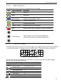
Figure index
Figure 1.
The AlarmView alarm system diagram ................................................................ 5
Figure 2.
Figure 3.
The Guardian alarm system .............................................................................. 6
The AVR visual Add-on ...................................................................................... 7
Figure 4.
Figure 5.
The control panel ............................................................................................ 10
The control panel keys ..................................................................................... 10
Figure 6.
Figure 7.
Control panel’s back side .................................................................................. 11
The LCD display and buttons ............................................................................. 12
Figure 8.
INFO screen example ....................................................................................... 13
Figure 9.
Figure 10.
The back of the circuit’s cradle .......................................................................... 17
Wall mounting diagram .................................................................................... 18
Figure 11.
External siren wiring scheme ............................................................................ 20
Figure 12.
Trigger connections ......................................................................................... 20
Figure 13.
OutView connection diagram ............................................................................. 52
3
Wireless Alarm Systems Installation Guide
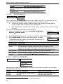
NOTICE AND DISCLAIMER
This guide will help installers and operators in the safe and efficient installation and use of the wireless
systems described herein.
Before trying to install and use the systems, read this guide and become familiar with all safety
requirements and operating procedures.
The system must not be used for purposes other than those for which it was designed.
The use of the software associated with the system is subject to the terms of the license
provided as part of the purchase documents.
PIMA Electronic Systems Ltd.’s exclusive warranty and liability is limited to the warranty and
liability statement provided in this manual and the peripherals guide (P/N 4410399).
This guide describes the maximum configuration of the systems with the maximum number of
functions, including future options. Therefore, not all functions described in this guide may be
available in a specific system.
Warnings are given for situations and circumstances in which a possible hazard can arise.
Cautions are given for situations or circumstances in which the system can possibly be damaged.
Notes are given for situations that need special attention, or to improve the operating procedure.
Wrong operation, or failure of the operator to effectively maintain the system, relieves the
manufacturer (and seller) from all or any responsibility for consequent noncompliance,
damage, or injury.
The text and graphics contained in the guide are for the purpose of illustration and reference
only. In no event shall manufacturer be liable for any special, direct, indirect, incidental,
consequential, exemplary or punitive damages (including, without limitation, any and all
damages from business interruption, loss of profits or revenue, cost of capital or loss of use of
any property or capital or injury).
Graphic signs in this guide
Icon
Description
Caution
Issues that may cause malfunctions
Warning Issues that may cause damage and actual bodily harm
Note
4
Important note
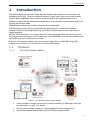
Introduction
1
Introduction
This guide will help you to install PIMA’s Wireless Intruder Alarm Systems: the AlarmView, the
Guardian and the AVR. The three systems are easy to install, plug-n-play, and provide wireless
intruder alarm capabilities, with or without Visual-Verification and optional remote Look-in.
Suitable for residential and small business applications, they present a comprehensive solution for
security and personal safety.
PIMA Wireless products also include a range of various peripherals.
The AlarmView’s unique offering incorporates the SmartView PIR /Camera that combines
movement detection and image capturing, the OutView Wireless camera and a wide range of
regular detectors.
With the Visual Verification, on an alarm event, the cameras transmit both the alarm event and
the images to the control panel, which sends them over GPRS/GSM to the Monitoring Station, and
optionally to the user’s mobile phone or email.
Note that all three alarm systems have two versions: Single SIM, and Dual SIM. Single SIM
systems cannot utilize any of the features of the dual SIM systems.
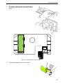
1.1
1.1.1
Features
The AlarmView system
Figure 1. The AlarmView alarm system diagram
Visual Verification images are sent to the system’s contacts, by MMS and E-mail. See
the AVR section on page 7 for details
Remote Look-in images requests, by text messages from the mobile phones
Remote Upload/Download initiation by the IP Receiver (without SMS)
5
Wireless Alarm Systems Installation Guide
Wireless peripherals including movement/smoke detectors, panic buttons, wireless
keypad, key fobs, door contacts, etc.
“SmartView” detector and camera:
“Matched field-of view” between the detector and the camera, with no dead spots
Flash correction in lowlight
High quality color images
OutView outdoor camera
Double and Backup reporting
Optional dual SIM
End-user notifications by SMS, MMS & E-mail
Alarm reporting options:
ContactID and SIA, via GPRS with SMS back-up
Images via MMS and E-mail
MMS (Multimedia Messaging Service) requires Internet plan and costs money,
including the text messages and emails sent via this service
Remote end-user commands by text messages
Built-in Quad Band GSM/GPRS modem, with SMS as backup
Advanced wireless visual link:
Two way supervised and secured radio network
128-bit encryption key
Supervision report every 10 sec
2.4 GHz FHSS (Frequency Hopping Spread Spectrum) & Diversity receiver (2 antennas)
Supervised 868 MHz link for standard wireless peripherals
Three programmable trigger inputs
PGM output
Graphic, user-friendly menu-driven LCD display
Easy battery replacement
Smartphone applications for controlling the AlarmView
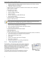
1.2
The Guardian system
The Guardian is a full featured wireless alarm system, designed to
answer the needs of most residential and small office installations.
Based on the AlarmView system, it lacks the Visual capabilities,
including Visual Verification and look-in image options.
The Guardian peripherals are the same as those of the AlarmView,
except visual detectors and cameras.
The Guardian alarm system cannot be upgraded to include the
complete enhanced visual features of the AlarmView system.
6
Figure 2. The Guardian
alarm system
Introduction
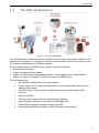
1.3
The AVR Visual Add-on
Figure 3. The AVR Visual Add-on
The AVR allows adding Visual Verification capacities to any Intruder Alarm System. Based on the
AlarmView control panel, it is designed for sending Visual Verification and look-in images by up to
six SmartView PIR/Cameras and OutView cameras.
By using trigger inputs and a PGM output, the AVR can do the following:
Be Armed and Disarmed
Trigger the external Alarm System
Serve as a GSM backup communication channel - when triggered by the external Alarm
System (on alarm, for example), the AVR will report the CMS/End-user
The AVR features are:
Six SmartView PIR/Cameras or OutView cameras
Trigger inputs: two for Arming and Disarming, one for communication Backup of the
external alarm system
One PGM output. It can be used for cellular backup of the master system alarm
reporting
Optional dual SIM
Two way communication with the SmartView and OutView
Alarm & image notifications to contacts via MMS/SMS/E-mail
Remote look-in images by contact requests (via SMS)
Remote Upload/Download initiation by the IP Receiver (without SMS)
7
Wireless Alarm Systems Installation Guide
1.4
Technical specifications1
General
Number of zones
Wireless Peripherals
Arming modes
Alarm types
Built-in siren
External siren
Event log
Codes
Special functions
Up to 30: 23 wireless, 1 hardwired, 6 visual
Up to 6 key fob remotes, or keypads
Up to 6 Panic buttons
External siren
AWAY/HOME/PART
Silent, siren or sounder
Piezoelectric, 85 dBA at 3 m
1 siren, wireless (indoor/outdoor)
256 events, non-volatile, with time and date stamp
8 codes, 4 to 8 digits each (numeric value 1-4):
Master user
4 Regular users (or up to 4 digit code, numeric value 0-9, with
external keypad)
Duress code
Limited 24H code
Installer code
Remote control by SMS from one (predefined) mobile phone,
ensuring privacy and security.
Remote Look-in via MMS Local USB connection for setup and
firmware upgrade
1 PGM output, 3 trigger inputs + trigger #1 can serve as zone #24
Time and date stamp
I/O
Real-time clock
Wireless
Advanced wireless link for visual zones
Frequency Band
2.4 GHz ISM band
TX Power
Up to 100 mW
Transmission method
2-way communication
GFSK
Frequency Hopping Spread Spectrum (FHSS)
Supervision
Up to 20 seconds
Secured wireless
48-bit factory set ID code
network
Built-in security using a link key (prevents unauthorized
access)
Data encryption (up to 48-bit)
Expected range2
Up to 100 m (outdoors)
Wireless link for standard peripherals
Frequency
868.6375 MHz
Supervision
Randomly, every 20-50 m + on every transmission
Transmission method
FM, narrow band
Expected Range
Up to 100 m outdoor. Can be extended indoors using the RP-15 Repeater
Communication
Modem
Interface
Quad-band GSM/GPRS
Report destinations
CMS Receivers, mobile phones, Email accounts
Reporting formats
SMS/MMS/Email (by SMTP)/GPRS-IP
1
2
8
The specifications of the detectors and accessories can be found in the peripherals guide (P/N 4410399)
Range is impacted by building materials and interference
Introduction
End user contacts
CMS contacts
Others
Physical Characters
Casing
Environmental Data
Operating temperature
Storage temperature
Humidity
Electrical Data
Power supply
Current drain
Backup battery
Weight:
With battery
Without battery
Dimensions
Reporting options/formats:
GSM/GPRS, SMS/MMS/Email (via mms) notifications
Four cellular phone numbers
Four email accounts
Reporting options/formats: GSM/GPRS, SMS/MMS/Email (via mms)
notices
Two IP address
Two phone numbers
Two Email accounts
Plastic - PC/ABC 94/V0
-10ºC - +49ºC
-25ºC - +70ºC
85%, non-condensed
+12VDC/1A
100 mA standby, 0.7A peak
+4.8 VDC,
4 x Ni-MH 2 Ah
687 gr
577 gr
225 x 138 x 40 mm
The control panel reports on Low Battery condition 9-12 hours after AC loss.
1-4 hours later it will turn off. Overall, the control panel can stay more than
12 hours in standby mode
We recommend using original AC adaptor and backup battery pack
from PIMA Electronic Systems
9
Wireless Alarm Systems Installation Guide
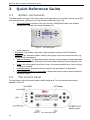
2
Quick Reference Guide
2.1
System components
The alarm system consists of the control panel, and depending on the model, wireless zones (23),
one hardwired zone, visual zones (6) and wireless peripherals (up to 36).
The Control Panel: consists of the main circuitry, GPRS/GSM module, two wireless
transceivers - standard and visual dedicated one.
Figure 4. The control panel
Visual detectors:
SmartView: high quality, supervised, rapid-acquisition camera, with PIR detector.
OutView: high resistance outdoor camera, with trigger input from external sources, e.g.,
PIR detectors and magnets.
Wireless detectors: the AlarmView system supports a wide range of wireless detectors,
including door contacts, PIR and Pet-immune motion detectors, Smoke detectors, etc.
Sirens: the control panel has a built-in siren. An external wireless siren (with a strobe)
can also be installed.
Keyfobs/keypads: accessories that are used to arm and disarm the AlarmView.
Panic/Medical pendant and wrist watch: accessories that are used to send emergency
and panic signals.
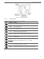
2.2
The Control Panel
The next figures show the control panel’s buttons and parts. The three arming buttons are
disabled in the AVR.
Figure 5. The control panel keys
10
Quick Reference Guide
Figure 6. Control panel’s back side
2.2.1
The buttons
The table below details the buttons of the control panel.
Button
Function
Press to…
AWAY
Arm to AWAY (full) mode
HOME
Arm to HOME mode
PART
Arm to PARTIAL mode
Left
Access the menus, Select and Insert
Right
Display the system’s Status, Cancel and Delete
OK
Confirm, Enter
Up
Scroll, type the characters A-Z, 0-9, #+_!@- space
Down
Left
Scroll, Exit, Back, and the numeral 4
Right
Scroll, Enter, Duplicate previous character, and numeral 2
11
Wireless Alarm Systems Installation Guide
2.2.2
The display
The LCD screen displays the status, the current time, and the cellular provider and reception. See
the following diagram for details.
Figure 7. The LCD display and buttons
2.2.2.1
The icons
The available icons are:
Transmission of SMS message
Low backup battery
GSM reception level
Battery loss
GSM network error
SIM1 active, fault
AC loss
SIM2 fault3
GPRS transmission
SIM1+2 fault3
2.2.3
Sound indications
The table below lists the sounds the Control Panel sounds.
Tones
Sound
Sounded when
♪
♪-♪
♪-♪-♪
♪-♪-♪-♪…
♪--------♪
Single beep
A key is pressed
Two beeps
A menu timeout occurs – exit to main menu
Three beeps
Successful command or operation
Continuous beeps
Entry/Exit delay mode
Long beep
Illegal command or entry refusal
Chime
Chime is activated
3
Displayed only in dual SIM systems
12
Quick Reference Guide
2.2.4
LED indications
The table below shows the LED color indicators and their meaning.
LED
2.2.5
Color+ Behavior
Indication
Green
Power on
Blank
Power loss
Blue, blinking
Wireless communication is active
Green, blinking
Cellular connection - OK
Off
No cellular connection
Orange, 3 blinks
Message waiting to be processed
Red
System trouble. See LCD display for further information
White, blinking
Alarm triggered - all arming modes. Blinking will
stop when re-arming, or entering the system log
The INFO screen
The INFO screen shows a grid of all active zones (up to #30, including visual zones, where available)
in several status options. To display it, press the INFO button
1
2
12
T 4
B B X
21
24 25
6
T
7
when the system is disarmed.
9 10
17 18
27
29
Figure 8. INFO screen example
The next table explains the various zone indications. A zone with more than one status toggles
between them, at one second interval.
Status
Description
Empty cell Undefined zone
Defined zone,
1-30
Normal mode
Open zone
Zone tamper open
T
B
X
Zones in the above example
19, 20, 30
1, 2, 4, 6, 7, 9, 10, 12, 17, 18,
21, 24, 25, 27, 29
5, 22, 23
3, 26
Bypassed zone
Low battery
Supervision loss
13, 14
Alarm
8, 16, 28
11
15
13
Wireless Alarm Systems Installation Guide
3
System Installation
3.1
General guidelines
The control panel should be installed at a location with optimum wireless reception from
the detectors and peripherals.
A convenient location for mains electricity supply and for user operation, near the main
access point is preferable.
For control panels which are operated using remote keypads, the panel can be
concealed inside a cupboard or loft space in a convenient location for mains electricity
supply.
3.2
Quick installation
For quick installation, you can mount the control panel on any flat surface. To do that, do
the following:
1.
On the back side, release the crosshead (“Philips”)
screw of the battery compartment and remove the
cover. The battery lies in the compartment, not
connected
2.
Connect the battery wires to the socket
14
System Installation
3.
Close the compartment and fasten the screw
4.
Remove the plastic protector of the connectors
cavity, by applying pressure with a flathead
screwdriver
5.
Insert the SIM card(s) to the SIM holder:
6.
a.
In single SIM versions, insert the SIM card into the upper slot (labeled “SIM-1 Main”)
b.
In dual SIM versions, first insert the backup SIM into the lower slot (labeled “SIM-2
Backup”), and then insert the main SIM into the upper slot (labeled “SIM-1 Main”).
See the next figure
Do not use PIN Code SIM cards
Do not insert SIM cards under power (AC or DC)
Plug the AC adapter into its socket, to the left
of the SIM card holder
Do not connect the AC adapter
to power before connecting it
to the control panel
7.
Attach the plastic protector back in place and
pass the AC wires through the wires path
8.
Connect the AC adapter to power. Wait for
the Power LED
to light up and the LCD
screen to show the normal display
9.
Ensure good reception of the wireless and GSM communications (see section 7.1.1.2,
on page 28)
15
Wireless Alarm Systems Installation Guide
10. Secure the control panel to the designated surface:
drill two holes, corresponding to the two keyhole
hangers on the back plate (see the image below),
and fasten the supplied screws, leaving a small
space between the screw head and the surface
11. Hang the control panel
3.3
Professional mounting
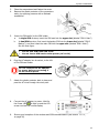
If the control panel needs to be secured with the tamper protection, do the following steps:
1.
Open the cover: insert a small slotted
screwdriver into the two slots at the bottom of
the control panel and apply pressure upwards
2.
Lift and remove the front cover
16
System Installation
3.
Pull out the plastic cradle of the circuit board,
by pulling its two clips on both sides, and turn
it over
SIM-1
Main
SIM-2
Backup
Figure 9. The back of the circuit’s cradle
4.
Connect the battery wires to the socket
17
Wireless Alarm Systems Installation Guide
5.
6.
Insert the SIM card(s) to the SIM holder:
a.
In single SIM versions, insert the SIM card into the upper slot (labeled “SIM-1 Main”)
b.
In dual SIM versions, first insert the backup SIM into the lower slot (labeled “SIM-2
Backup”), and then insert the main SIM into the upper slot (labeled “SIM-1 Main”).
See the previous figure
Do not use PIN Code SIM cards
Do not insert SIM cards under power (AC or DC)
On the designated surface, drill holes, corresponding to those marked with arrows on the
next figure and insert drywall plugs into them. Note, that the hole in the middle is designated
for the tamper switch’s knockout4
The tamper switch knockout must be secured with a dedicated screw, to
comply with EN50131-1 regulation
195mm
29mm
70mm
Tamper switch
knockout
Figure 10. Wall mounting diagram
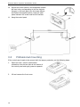
7.
Route the AC adapter’s plug and wires through the wires path. See the next figure.
8.
Secure the back plate to the surface with screws.
4
When the control panel is forcibly removed from the wall, the knockout breaks and the tamper is activated
18
System Installation
9.
Plug the AC adapter into its socket, to the
left of the SIM card holder
Do not connect the AC adapter
to power before connecting it to
the control panel
10. With the LCD screen facing you, insert the
cradle into the mounted back plate - push
it firmly, until the clasps are locked.
Ensure the back tamper is pressed
against the knockout
11. Tilt the front cover towards top of the
mounted back plate
12. Insert the two jags on the front cover to the
corresponding holes on the back plate, and
push it down, until you hear an audible press
13. Press the front cover against the back plate,
until locked
14. Secure the front cover with the two supplied
Philips screws, at the bottom
15. Connect the AC adapter to power. Wait for
the Power LED
to light up and the
screen to show the normal display
19
Wireless Alarm Systems Installation Guide
3.4
Other installation options
3.4.1
Standalone wired siren
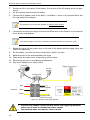
Besides the control panel’s built-in siren, you can also connect any self-powered external siren.
To do so, you will need to connect it to an external power source.
The wired siren’s current consumption should not exceed 500 mA
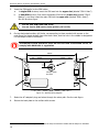
To connect the siren:
1.
Run the siren’s wires through the opening on
the control panel’s back plate
2.
Connect between the siren and the control
panel’s PGM terminals. See the scheme on
the right
3.
Connect between the siren, the control panel
and the external power source (-)
4.
Connect between the siren and the external
power source (+)
+ 12V -
-
How to use the trigger inputs
+
External
power source
Figure 11.
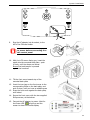
3.4.2
TR1 COM TR2
TR3 COM PGM
+
-
PGM
External siren wiring scheme
5
The alarm system has three inputs listed in the next table, which can be used to arm and disarm
it by triggers from external alarm systems. See the next sub-section on the AVR.
Input
Optional Use
TR1
arming to AWAY mode
TR2
arming to HOME mode
TR3
arming to PART mode
When using the triggers for arming and disarming, the control panel’s quick
arming buttons are disabled
Connect the triggers according to the next diagram.
+ 12V -
TR1 COM TR2
TR3 COM PGM
From PGM/
ALARM outputs
Figure 12. Trigger inputs
5
See section 1
0.5.4, on page 43 for the triggers’ settings
20
System Installation
3.4.3
The AVR
The AVR adds Visual Verification capacities to any Intruder Alarm System. Based on the
AlarmView control panel, it is designed for sending Visual Verification and look-in images by up to
six SmartView PIR/Cameras and OutView cameras.
The AVR is defined as “Slave” when connected to an external alarm system (“Master”).
By using trigger inputs and a PGM output, the AVR can do the following:
Be Armed and Disarmed
Trigger the external Alarm System
Serve as a GSM backup communication channel - when triggered by the external Alarm
System (on alarm, for example), the AVR will report the CMS/End-user
By default, the AVR will use the triggers as follows:
Trigger Default setting Connect the input to…
#1
Wired/External
zone
External alarm system’s Alarm output. The input will serve as a
backup communication channel - when the Alarm output will be
triggered (on alarm, for example), the AVR will report the CMS/ enduser. Make sure zone #24 (the wired zone) is set as 24H zone6
#2
AWAY arm
External alarm system’s On/Off output. The input will be used for
arming AWAY the AVR (and disarming it) by the external alarm system
#3
Not used
3.4.3.1
-
How to connect the triggers to the external alarm system
Use the following diagram and table to connect the trigger inputs of the AVR.
AVR (“Slave”)
Trigger inputs
External Alarm
System (“Master”)
PGM/Alarm Output
COM
On/Off Output
COM
Figure 13. The AVR trigger inputs
AVR
Alarm system
TR1
PGM/Alarm Output
TR2
On/Off Output
6
“Swinger Shutdown” must be disabled
21
Wireless Alarm Systems Installation Guide
3.4.3.2
How to connect the PGM output to the external alarm system
By default, the PGM output is used by the AVR to report on “Not Ready/Alarm” (open zone,
faults, and alarms) situations. It is set as Normally Closed. See section 10.5.3, on page 43 for
details on the PGM output options.
External Alarm
System (“Master”)
AVR (“Slave”)
PGM Output
Zone Input
Figure 14. The AVR PGM output
3.4.4
External antenna
The control panel has a model with a connector for external GSM
antenna (P/N 6110019), to improve GSM reception where necessary
This control panel model must be ordered separately!
3.5
How to confirm system installation
To make sure all detectors are well identified by the control panel after installation, do the following:
1.
Access the Installer menu and select Service -> Tests -> Zone Tests
2.
Press the Test button on each detector and check the reception level. See section 7
.1.1.2,
on page 28 for details
22
Setup and Programming
4
Setup and Programming
The alarm system has two menus and two related passwords: Installer and Master User. The
two menus have the same sub-menus, except the Programming menu which is exclusive to
the Installer.
Programming can also be done remotely, using PIMA’s Programming Tool software7.
Some menus are feature depended and vary between models
4.1
The Installer’s menu map
OPTIONS
GLOBAL SETTINGS
BACK
ZONE BYPASS
CONTACTS
EVENT LOG
BACK
SERVICE
TESTS
BACK
ENABLE PROGRAMMING
DISPLAY VERSION
SYSTEM RESET
PASSWORDS
REGULAR USERS
BACK
MASTER USER
DURESS CODE
24H LIMITED CODE
INSTALLER
SET CLOCK
TIME
BACK
PROGRAMMING
DATE
ZONES/PERIPHERALS
BACK
CONTACTS
CMS CONTACTS
COMMUNICATION
SYSTEM OPTIONS
FACTORY DEFAULTS
LOCAL PROGRAMMING
FIRMWARE UPGRADE
STOP COMM.
BACK
7
Version 02.00.11.00 and higher
23
Wireless Alarm Systems Installation Guide
4.2
Accessing the menus
To access either of the menus:
1.
2.
Press the left key
field will appear
(under “MENU”) - a password entry
ENTER PASSWORD
DELETE
Use the numeric/navigation keys to enter a password. See section 2
.2.1, on page 11, on how
to enter characters
4.3
The Master and Installer passwords
The next table lists the Master user and Installer passwords and their use.
Password
Default The password allows…
Master user
1111
Changing all passwords except the Installer’s, viewing the event log,
setting the time, and changing some system settings
Installer
1234
Changing the Installer password, changing all settings the control
panel and all detectors and peripherals
You must change the default passwords during the installation of the
system
4.3.1
How to reset the passwords to factory defaults
To reset the passwords to their factory default:
1.
Disconnect the control panel from both AC power and backup battery for 10 sec.
2.
When you power up the control panel again, the Master User and Installer’s default
passwords (1111, 1234 respectively) can be used for 30 sec. to access the menus
24
Options menu
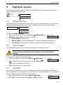
5
Options menu
This menu allows changing and controlling the general behavior of the Control Panel as well as
setting notifications for the contacts.
OPTIONS
GLOBAL SETTINGS
BACK
ZONE BYPASS
CONTACTS
5.1
Global Settings
The Global Settings menu allows setting of three features, as explained below. The remote look-in
and visual events features allows the end user to maximize the control of all privacy issues.
GLOBAL SETTINGS
GLOBAL CHIME
REMOTE LOOK-IN
VISUAL EVENTS
To change the Global Settings:
1.
Access the Installer menu and select Options Global Settings
2.
Set/Clear (enable/disable) the options, which are:
GLOBAL SETTINGS
T GLOBAL CHIME
T REMOTE LOOK-IN
SET/CLEAR
a.
Global Chime: all chime zones
b.
Remote Look-in: sending requested look-in images to predefined mobile phones
c.
Visual Events: sending visual verification images to predefined mobile phones
5.2
CANCEL
Zone bypass
This menu allows bypassing zones until the next disarming of the alarm system
Do not bypass zones unless necessary and only temporarily: bypassed
zones do not sound the alarm when opened, nor are reported to
the CMS
To bypass zones temporarily, do the following:
1.
Access the Installer menu and select Options Zone Bypass
ZONE BYPASS
2.
Set (enable) the zones to be bypassed. Press the Up/Down
SET/CLEAR
3.
Clear (disable) zones to un-bypass them
£ ZONE 1
£ ZONE 2
CANCEL
keys to scroll between the zones
5.3
Contacts
This menu allows setting which of the six available contacts will get notifications on alarms and
other system events. The events are set in the “Contact 1-6” menu. See section 10.2.2, on page 37.
To set a contact to receive notifications, do the following:
1.
Access the Installer menu and select Options Contacts
2.
Press Set to enable a contact, press Clear to disable a contact
CONTACTS
T CONTACT 1
T CONTACT 2
SET/CLEAR
CANCEL
25
Wireless Alarm Systems Installation Guide
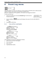
6
Event Log menu
EVENT LOG
BACK
This menu allows you to view the system log. The log keeps the last 256 events. While the alarm
system is armed, it can log up to 10 events from the same zone.
Using the “Programming Tool” application, 500 events can be logged and viewed.
To view the Event Log:
1.
Access the Installer menu and select Event Log. The first event is
the most recent one
21/5/14
07:33:20
124
Full Arm (Away)
System (AlarmView)
CANCEL
2.
Use the Up/Down
details.
3.
Press
6.1
keys to scroll between the events. See the next section for
to exit the log
Log entry examples
1
2
3
21/05/14 07:33:20
31
Supervision Loss
ZONE 11 (Room 6)
CANCEL
1
2
3
02/06/14 22:03:20
105
Alarm from Zone
ZONE 20 (Bath)
4
CANCEL
1
17/11/14 20:47:20
2
3
4
16
Full Arm (Away)
System (AlarmView)
4
CANCEL
The information of a log entry is displayed as follows:
1.
Date and time the event was logged
2.
Event description
3.
Event source
4.
Log entry serial number
26
Service menu
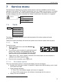
7
Service menu
The Service menu allows you to perform various tests to verify the installation and the proper
operation of the system. The “Enable Programming” menu is a Master user only menu - it enables
the user to allow a two hour remote access to the alarm system. If the default Access Code has
not been changed, this option overrides the “Always” access mode. See section 0, on page 44
SERVICE
TESTS
BACK
ENABLE PROGRAMMING
DISPLAY VERSION
SYSTEM RESET
7.1
Tests
TESTS
ZONES
EXTERNAL SIREN
BUILT-IN SIREN
COMMUNICATION
SYSTEM SELF TEST
The tests menu allows testing the zones and peripherals of the alarm system and some
more options.
Testing the system periodically will ensure the system owner that the system works properly.
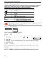
7.1.1
Zones
To test the zones:
1.
Access the Installer menu and select Service
Tests Zones
1
3
11 12
4
5
6
8
16 17
2.
The zone test screen is made of a grid that shows all
active zones: zones 1-24 are displayed with their
number, zones 25-30 are displayed with their RSSI8
level. See the next two sub-sections for full details.
3.
Trigger zones 1-24 - when a signal is received in the control panel, the zone number is
replaced by the RSSI reception level.
4.
Once the test is complete, press
7.1.1.1
9 10
20
26
to exit.
Zone status options
There are three status options in the zone test display (see the next figure):
a. Number: this is the zone number. It appears in regular zones before testing, and in visual
zones that are at fault
b. Signal strength indicators:
1) Zones 1-24: the indicators appear as the zone is triggered
2) Zones 25-30 (visual zones): the indicators interchange with the zone no.
c. Empty: the zone is disabled
8
Received Signal strength Indication.
27
Wireless Alarm Systems Installation Guide
7.1.1.2
RSSI reception level
The signal strength indicators allow you to determine how good the communication, between the
wireless devices and the control panel is. The number of the indicators is the quality of the
reception, as explained in the table below. See also the previous figure
Onscreen
Indicators Reception/Indication
5
Excellent
4
Strong
3
Good
2
Low: see the warning below!
1
Poor: see the warning below!
Numeral
-
1.
Zones 1-24: the zone was not triggered
2.
Zones 25-30: the (visual) zone is at fault
"Poor” and “Low” reception levels are not acceptable. If you get a "poor"
signal from any detector, re-locate it and re-test it, until the test result is
between "Excellent" and "Good"
7.1.2
External Siren
EXTERNAL SIREN
TEST
STOP SIREN
RELEARN
See also External Siren Indications, on page 53
7.1.2.1
Test
To test the external siren, do the following:
1.
Access the Installer menu and select Service Tests
External Siren
2.
Press Test
3.
Wait 5 sec. The siren will sound the alarm for 3 sec. and its LEDs will flash for few sec.
4.
Press
7.1.2.2
EXTERNAL SIREN
SELECT
to exit
Stop siren
If the siren’s tamper switch is tripped continuously, you can use this feature to stop (silent)
the siren.
7.1.2.3
Relearn
If the siren needs to be re-learned with the control panel, call PIMA support for instructions
28
1
TEST
STOP SIREN
BACK
Service menu
7.1.3
Built-in siren
To test the built-in siren, do the following:
1.
Access the Installer menu and select Service Tests Built-In Siren
2.
Press
7.1.4
- the built-in siren will sound briefly
Communication
COMMUNICATION
SIM 1(MAIN)
GPRS LINK
SIM 2(BACKUP)
CMS 1-2
CONTACT 1-6
This menu allows testing the SIM card’s communication setup, by trying to send and receive data.
See the next table for complete details.
To test the SIM cards:
1.
Access the Installer menu and select Service Tests
Communication
COMMUNICATION
SIM 1(MAIN)
SIM 2(BACKUP)
SELECT
2.
Select SIM1 or SIM2 (in dual SIM versions). If the selected SIM is
currently idle, the alarm system will switch to it
3.
Select the test type and press
4.
Press
7.1.4.1
BACK
COMMUNICATION
GPRS LINK
CMS 1
SELECT
BACK
at the end of the tests
Test types
The test types are described in the below table. All tests are replied by either “Passed” or
“Failed” message
Test
Process
GPRS Link
Ping a website (www.google.com)
CMS 1-2
Send a test event to the CMS:
Contact 1-6
7.1.5
a.
In SIA/CID over SMS: to mobile phone
b.
In Visual/CID over Email: to E-mail
c.
In Visual/CID over GPRS: to PC, mobile phone
Send “Periodic Test” by text message:
a.
SMS Test: to mobile phone (“SMS Event Report” must be enabled.
See page 37)
b.
Email Test: to E-mail (“Email Event” must be enabled. See page 37)
System self-test
The self-test checks the LCD display, the LEDs and the chime
To do the test:
1.
Access the Installer menu and select Service Tests System Self Test
2.
The LCD display will flicker for eight sec. and the internal sounder will sound a series of beeps
29
Wireless Alarm Systems Installation Guide
7.2
Display version
Use this feature to view the system’s version and RF frequency
To view the system version and frequency:
1.
2.
Access the Installer menu and select Service Display Version
The system’s software version and RF frequency will be displayed
Press
7.3
ALARMVIEW.STD.EN
02.09.07.00.000
FREQ:868.635
to exit
System reset
The system reset feature enables to reset the communication channels.
To do a system reset:
1.
Access the Installer menu and select Service System Reset
2.
Wait for the short process to end. While resetting, the message
UPDATING is displayed
30
AlarmView
UPDATING
OK
Passwords Menu
8
Passwords Menu
PASSWORDS
REGULAR USERS
BACK
MASTER USER
DURESS CODE
24H LIMITED CODE
INSTALLER
The password menu allows you setting the Installer password. The other passwords on the menu
can be set only by the Master User, in the User menu.
8.1
Installer
The Installer password can be 4-8 digits long and contain the numeric values of 1-4, for example
14412311. It cannot be deleted.
You must change the default Installer password during installation
To set the Installer password:
1.
Access the Installer menu and select Passwords Installer
2.
Select Password and type the desired password
3.
Press
INSTALLER
PASSWORD
ACCESS MODE
SELECT
BACK
You cannot use the Installer password over the wireless keypad, only the
control panel
A minimum of 7 digit password is required to comply with EN requirements
8.1.1
Access mode
There are two options for allowing the installer to access the alarm system remotely, via the
Programming Tool application: User Initiated and Always, explained below.
The AlarmView keeps a record of any remote connection and reports it to the CMS.
a.
User Initiated: in this mode the Installer cannot access the menu, unless the Master
user permits it by opening a two hour access window (on the User menu: Service
Enable Programming)
b.
Always: in this mode the Installer can access the system without the need for the
Master user approval
You must change the default Access Code, to be able to connect to the
alarm system remotely in the “Always” mode: as a precaution, if the
default code has not been changed, remote access without the Master
user approval is disabled
31
Wireless Alarm Systems Installation Guide
To define the Installer’s access mode, do the following:
1.
2.
Access the Installer menu and select Passwords Installer
Access Mode
Select User Initiated or Always
9
INSTALLER
1
P USER INITIATED
ALWAYS
CANCEL
SELECT
Set Clock menu
SET CLOCK
TIME
BACK
DATE
After a long power failure, or whenever the time is not accurate, the time and date need to be set
9.1
Time
To set the Time, do the following:
1.
Access the Installer menu and select Set Clock Time
2.
Press
formats
3.
Press the up and down arrow keys
to set the hour and minute
4.
Press the right and left arrow keys
minutes
to move the cursor between the hours and the
5.
Press
9.2
to change between 12H (AM/PM) and 24H time
22 : 17
AM-PM/24H
CANCEL
to save
Date
To set the Date, do the following:
1.
Access the Installer menu and select Set Clock Date
2.
Press
to set the date format to either American (MM/DD)
or European (DD/MM)
3.
Press the up and down arrow keys
to set the date
4.
Press the right and left arrow keys
and year
to move the cursor between the day, month
5.
Press
32
to save
16 / 05 / 14
DD-MM/MM-DD
CANCEL
Programming menu
10 Programming menu
The programming menu allows you to program the various functions of the alarm system.
PROGRAMMING
BACK
ZONES/PERIPHERALS
CONTACTS
CMS CONTACTS
COMMUNICATION
SYSTEM OPTIONS
FACTORY DEFAULTS
LOCAL PROGRAMMING
FIRMWARE UPGRADE
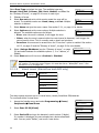
10.1
Zones/Peripherals
Enroll and define the wireless detectors and peripherals of the alarm system. Before enrolling,
make sure all peripherals have the appropriate batteries.
All three systems, the AlarmView, Guardian and AVR support up to 23 wireless zones and one
hardwired. The AlarmView and AVR also support up to six Visual zones.
10.1.1
ZONES
Zones
ZONE 1-24
DEVICE ID
ZONE TYPE
ARM SET
NAME
OPTIONS
SWINGER SHUTDOWN
STATE
To enroll and define a wireless zone:
1.
Access the Installer menu and select Programming Zones/
Peripherals Zones
2.
Select Zone 1-249
ZONES
1
ZONE 1
ZONE 2
SELECT
BACK
ZONE 1
1
DEVICE ID
ZONE TYPE
SELECT
3.
4.
Select Device ID and press Learn
to enroll a detector or a
peripheral. If a number is displayed, the zone already has a device
associated with. You can press “Delete”, and enroll a new device
9
LEARN
CANCEL
LEARN DEVICE ID
Trigger a device or press its Test button. When the device is
detected, press
BACK
LEARN DEVICE ID
A1B2C344
DELETE
CANCEL
Zone #1 is set as Entry/Exit zone by default
33
Wireless Alarm Systems Installation Guide
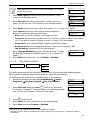
Select Zone Type and select the type. The available types are:
Normal, Entry/Exit, Follower, 24H, Panic, Medical, and Fire. See
the “Glossary of terms”, on page 55 for more on each type
5.
Glossary of terms
6.
Select Arm set and set to which arming mode the zone will be
armed. The available modes are: Home, Away, and Part. Multiple
selection is allowed
ZONE TYPE
SELECT
CANCEL
ARM SET
1
x HOME
x AWAY
SET/CLEAR
7.
Select Name and give the zone a name. See section 2
.2.1, on page 11 for details
8.
Select Options and set the zone options. Multiple selection is
allowed. The available options are as follows:
Siren: when the zone is violated, it will trigger the siren
1
P ENTRY/EXIT
FOLLOWER
CANCEL
OPTIONS
1
x SIREN
x CHIME
SET/CLEAR
CANCEL
Chime: when the zone is opened while the control panel is disarmed, it will trigger the
control panel’s chime. This is normally used on doors and windows
Force Arm: this zone can be armed when the “Force Arm” option is enabled. See section
10.5.2, on page 42 and the “Glossary of terms”, on page 54 for more details
9.
Select Swinger Shutdown (see the “Glossary of terms”, on page
54) and select between the available options: 1, 2 or 3 alarms, or
Disable
SWINGER SHUTDOWN
4
P 3 ALARMS
DISABLE
SELECT
BACK
10. Select State and set if the zone is Enabled or Disabled.
Zone #24 is a dedicated hardwired zone. As such, it does not have the “Device
ID” option. To use this zone Trigger #1 must be set as “Wired/EXT zone”. See
section 10.5.4, on page 43
10.1.2
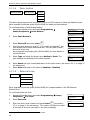
Visual zones (AlarmView and AVR only)
VISUAL ZONES
ZONE 25-30
(VISUAL)
DEVICE ID
ZONE TYPE
ARM SET
NAME
OPTIONS
SWINGER SHUTDOWN
STATE
The alarm system supports up to six visual zones, namely SmartView PIR/cameras.
To enroll and define a visual zone:
1.
Access the Installer menu and select Programming Zones/
Peripherals Visual Zones
2.
Select Zone 25-30 (Visual)
3.
Select Device ID and type the detector’s serial number (8 digits).
If a number is displayed, the zone already has a device associated
with. You can press “Delete”, and enroll a new device
VISUAL ZONES
SELECT
ZONE 25 (VISUAL)
BACK
1
DEVICE ID
ZONE TYPE
SELECT
34
1
ZONE 25 (VISUAL)
ZONE 26 (VISUAL)
BACK
DEVICE ID
00000000
INSERT
DELETE
Programming menu
Visual detectors cannot be enrolled automatically, to protect
privacy and security
DEVICE ID
33569874
INSERT
4.
Select Zone Type and mark the type. See the previous “Zone”
section for the available options
5.
Select Arm set and set the arming mode in which the zone be
armed. See the previous “Zone” section for the available options
DELETE
ZONE TYPE
1
P NORMAL
ENTRY/EXIT
SELECT
CANCEL
ARM SET
1
x HOME
x AWAY
SET/CLEAR
CANCEL
6.
Select Name and give the zone a name. See section 2
.2.1, on page 11 for details
7.
Select Options and set the zone options. Multiple selection is
allowed. The available options are as follows:
Siren: when the zone is violated, it will trigger the siren
OPTIONS
1
x SIREN
x FORCE ARM
SET/CLEAR
CANCEL
Force Arm: this zone can be armed when the “Force Arm” option is enabled. See section
10.5.2, on page 42 and the “Glossary of terms”, on page 54 for more details
Visual Verif.: send visual verification images to predefined contacts
Remote Look-in: allow predefined contacts to request look-in images by SMS
Led Indication: SmartView LED ON when alarmed
8.
Select Swinger Shutdown (see the “Glossary of terms”, on page
54) and select between the available options: 1, 2 or 3 alarms, or
Disable
9.
Select State and select if the zone is Enabled or Disabled
10.1.3
SWINGER SHUTDOWN
4
P 3 ALARMS
DISABLE
SELECT
BACK
Keyfobs/keypads
KEYFOBS/KEYPADS
KEYFOB/KEYPAD 1
DEVICE ID
NAME
STATE
The alarm system supports the connection of up to six KF key fobs and RWK wireless keypads.
See a separate Peripherals guide (P/N 4410399) for details on these devices.
To enroll and define a key fob or a wireless keypad, do the following:
1.
Access the Installer menu and select Programming Zones/
Peripherals Key fobs/ Keypads Key fob/Keypad X
KEYFOB/KEYPAD 1
1
DEVICE ID
NAME
SELECT
2.
Select Device ID and press Learn
to enroll the peripheral10
If a number is displayed11, the zone already has a device associated
with. You can press “Delete”, and enroll a new device
BACK
LEARN DEVICE ID
LEARN
CANCEL
LEARN DEVICE ID
A1B2C344
DELETE
3.
Press
4.
Select Name and type a description for the keyfob/keypad
5.
Select State and select Enabled or Disabled
10
11
CANCEL
to save the ID
Or type it: the ID is printed on a label on the keyfobs and keypad
Only the first seven digits are displayed (the eighth is always zero). The serial no. is printed on a label on
the detector
35
Wireless Alarm Systems Installation Guide
10.1.4
Panic button
PANIC BUTTONS
PANIC BUTTON 1
DEVICE ID
TYPE
NAME
STATE
The alarm system supports the connection of up to six PCP buttons for Panic and Medical issues.
See a separate Peripherals guide (P/N 4410399) for details on these devices.
To enroll and define a Panic/Medical button:
1.
Access the Installer menu and select Programming
Zones/Peripherals Panic Buttons
2.
Select Panic Button X
PANIC BUTTONS
SELECT
BACK
PANIC BUTTON 1
Select Device ID and press Learn
4.
Press the panic button to enroll it12. If a number is displayed11, the
zone already has a button associated with. You can press “Delete”,
and enroll a new one.
See a separate peripherals guide (P/N 4410399) for more details on
the panic button
5.
Select Type and select the button type: Medical or Panic. The
type selected only determines the event reported
1
DEVICE ID
TYPE
SELECT
3.
1
PANIC BUTTON 1
PANIC BUTTON 2
BACK
LEARN DEVICE ID
LEARN
CANCEL
LEARN DEVICE ID
A1B2C344
DELETE
TYPE
CANCEL
1
P MEDICAL
PANIC
SELECT
CANCEL
6.
Select Name and type a name/description for the panic button (see section 2
.2.1, on page 11
for instructions)
7.
Select State and select if the button is Enabled or Disabled
10.1.5
EXT. SIREN
External siren
DEVICE ID
START DELAY
CUT OFF
OPTIONS (AWAY)
STATE
See a separate Peripherals guide (P/N 4410399) for complete details on the SIR External
Wireless Siren.
To enroll and define the siren:
1.
Access the Installer menu and select Programming Zones/
Peripherals Ext. Siren
2.
Select Device ID
3.
Enter the siren’s serial number and press Insert
(see section
2.2.1, on page 11 for instructions). The number is printed on a label
at the back of the siren (and also on the siren’s package)
12
Or type it: the ID is printed on a label on the button
36
EXT. SIREN
1
DEVICE ID
START DELAY
SELECT
BACK
DEVICE ID
000000
INSERT
CANCEL
Programming menu
4.
If required, select Start Delay and enter a delay in sec. before the
siren will sound the alarm, between 0 (default) and 255
START DELAY
0
DELETE
INSERT
5.
Select Cut Off and enter the time, between 5 and 255 sec.
(default - 60)
CUT OFF
60
DELETE
INSERT
6.
7.
Select Option (Away) and set options, that are available only
while the alarm system is armed to AWAY mode:
OPTIONS (AWAY)
1
£ ARMING TONES
£ ENTRY/EXIT TONES
a.
Arming tones: the siren will beep once when arming the
system, and twice when disarming
b.
Entry/Exit tones: in addition to the control panel internal sounder, the siren will
sound clock ticks during the exit and entry delays. See “External Siren Indications”, on
page 50 for details
SET/CLEAR
CANCEL
Select State and select if the siren is Enabled or Disabled
10.1.6
Built-in siren
The system has an 85 dB internal siren, sufficient for indoor alarm.
To define the built-in siren:
1.
Access the Installer menu and select Programming Zones/
Peripherals Built-In Siren
2.
Select Cut Off and enter the time, between 5 and 255 sec. (default - 60)
3.
Select State and select if the siren is Enabled or Disabled
BUILT-IN SIREN
SELECT
10.2
CONTACTS
1
CUT OFF
STATE
BACK
Contacts
SYSTEM NAME
CONTACT 1-6
EVENT REPORT
The system allows defining up to six contacts, for receiving event and fault notifications.
10.2.1
System name
The system name is used to personalize the alarm system in the messages the contacts receive.
To define the name:
1.
Access the Installer menu and select Programming Contacts
CONTACTS
2.
Select System Name. Leave the default name or type a new one
(see section 2.2.1, on page 11 for instructions)
SELECT
3.
Press
10.2.2
1
SYSTEM NAME
CONTACT 1
BACK
Contact 1-6
Define the various details of up to six contacts of the alarm system, as follows:
1.
Access the Installer menu and select programming User
Contacts Contact X
CONTACT 1
SELECT
2.
1
MOBILE PHONE
EMAIL (BY MMS)
BACK
Select Mobile Phone and enter a mobile phone number
37
Wireless Alarm Systems Installation Guide
3.
Select Email (By MMS) and enter an E-mail address. E-mails are sent via MMS (Multimedia
Message Service) messages and cost money to the end user (by the service provider)
4.
Select Contact Name and type a name (see section 2
.2.1, on page 11 for instructions)
5.
Select Options and set the contact’s options, as described in the
next table
OPTIONS
1
x SMS REMOTE CMD.
x REMOTE LOOK-IN
SET/CLEAR
CANCEL
Option
The contact will be…
SMS Remote CMD.*
allowed to send arm, disarm and other commands by SMS.
See section 12.2.1, on page 48
Remote Look-in*
allowed to receive look-in images
SMS Event Report*
receiving notifications on alarms and other events by SMS
MMS Visual
receiving visual verification images by MMS
Email Event
receiving notifications on alarms and other events by E-mail
Email Visual
receiving visual verification images by E-mail (sent via MMS)
* Must be enabled when using the Android app
6.
Select Event Report and set the event types that will be reported
to any of the contacts. The options are as follows:
Alarm events: any alarm
EVENT REPORT
1
x ALARM EVENTS
x DIS/ARM REPORT
SET/CLEAR
CANCEL
Dis/Arm report: arming to any mode and disarming
Power report: power loss
Service report: actions such as entering the menu
See A
ppendix G, on page 57 for complete details on the reported events
10.3
CMS contacts
CMS CONTACTS
ACCT. ID
CMS 1-2
EVENT REPORT
RETRY OPTIONS
Here you can set two CMS contacts and their options.
To set the CMS contacts, do the following:
1.
Access the Installer menu and select Programming CMS
Contacts
2.
Select Acct. ID and type the account ID of this alarm system
3.
Select CMS X and set the following:
CMS CONTACT
SELECT
38
1
ACCT. ID
CMS 1
BACK
Programming menu
CMS 1-2
MOBILE
EMAIL (BY MMS)
IP
PORT
CMS PROTOCOL
PERIODIC TEST
GPRS ALWAYS ON
BACKUP*
* CMS 2 only
a.
Select Mobile and enter the CMS’s phone number for receiving notifications by SMS
b.
Select Email (by MMS) and enter the CMS’s E-mail address. Note that E-mails are
sent via MMS (Multimedia Message Service) messages and cost money to the end
user (charged by the cellular provider). See section 2.2.1, on page 11 for instructions
c.
Select IP and enter the IP address of the IP Receiver in the CMS. You can also enter a
URL address for DDNS services
d.
Select Port and enter the port number of the IP receiver
e.
Select CMS Protocol and select the relevant option. The
options are listed below
CMS PROTOCOL
SELECT
CMS PROTOCOL
1
P DISABLE
SIA SMS
CANCEL
DISABLE
SIA SMS
CID SMS
EMAIL VISUAL/CID
GPRS-CID
GPRS-VISUAL/CID
f.
g.
4.
Disable:
reporting to the CMS is disabled
SIA SMS:
events will be sent by SMS, in SIA
CID SMS:
events will be sent by SMS, in ContactID©
E-mail Visual/
CID:
visual and normal events will be sent by E-mail, in ContactID©
GPRS-CID:
events to the CMS will be sent as IP over GPRS, in ContactID©
GPRS-Visual/
CID:
visual and normal events will be sent to the CMS, as IP over
GPRS, in ContactID©
Select Periodic Test and select every how long a test event
will be sent to the CMS for supervision. The options are:
Disable (tests), 5 min, 10 min, 60 min, 24 hrs, one week, one
month
Select GPRS Always ON and select a ping interval in sec. The
options are: 30, 45, 60 or 90. The alarm system will ping a web
server to maintain an open session with the IP Receiver. See
the “Glossary of terms”, on page 54 for more details
PERIODIC TEST
1
P DISABLE
5 MIN
SELECT
GPRS ALWAYS ON
CANCEL
1
P DISABLE
PING 30 SEC
SELECT
CANCEL
Press BACK
39
Wireless Alarm Systems Installation Guide
5.
EVENT REPORT
1
Select Event Report and set which events will the alarm system
x BURGLARY REPORT
report the CMS. The options are: Burglary Alarms, Burglary Restore,
x BURGLARY RESTORE
SET/CLEAR
CANCEL
Fire alarms, Fire Restore, Arming and Disarming, Service events,
Service Restore, Power loss, Power Restore, Medical alarms, Medical Restore, and Visual
alarms (verification images)
6.
Select Retry Options and set the two available options. The alarm
system will retry to send events:
Interval Timeout: set the overall interval of the re-tries in
min., between 6-30
RETRY OPTIONS
1
INTERVAL TIMEOUT
DELAY TIMEOUT
SELECT
BACK
Delay Timeout: set the delay between re-tries in sec., between 15-60
Example: if you set an interval of 10 min. and a delay of 15 sec., then for 10 min. the
control panel will try to report the CMS, every 15 sec., which is 40 times (10x4)
7.
In CMS 2 only, select Backup and set the two backup options,
as follows:
Backup: CMS 2 will serve as backup to CMS 1 in case of a
communication fault with CMS 1
BACKUP
1
P BACKUP
DUPLICATE
SELECT
CANCEL
Duplicate: all events will be reported both to CMS 1 and CMS 2 (“Double Report”)
10.4
When CMS 2 is set as “Duplicate”, “GPRS Always On” is automatically disabled
Sending images may cause the IP Receiver to close the session
Communication
COMMUNIATION
SIM MODE
SIM 1 (MAIN)
SIM 2 (BACKUP)
Set the mode of the SIM card(s) - single or dual13 - and the cellular provider’s details of each card.
The alarm system comes with a list of your country’s providers by default.
To set the SIM card(s):
1.
Access the Installer menu and select Programming
Communication
COMMUNICATION
SELECT
2.
Select SIM Mode and select between the two following options:
Single SIM (Main): one card will be used
Dual SIM: two cards will be used
3.
Back in the Communication screen, select SIM1 (main) and
press Select Operator
SIM MODE
13
Using the up/down arrow keys
, scroll to the provider
that matches the SIM card in use by the alarm system, and
press Select
See the “Glossary of terms”, on page 49
40
BACK
1
P SINGLE SIM (MAIN)
DUAL SIM
SELECT
COMMUNICATION
CANCEL
1
SELECT OPERATOR
SELECT
4.
1
SIM MODE
SIM1 (MAIN)
SELECT OPERATOR (COUNTRY)
BACK
1
OPERATOR #1
OPERATOR #2
SELECT
BACK
Programming menu
5.
Press BACK. If you need to select a different country, scroll to
it, press Select, then repeat on steps 3-4
6.
In dual SIM versions, select SIM2 (Backup)
SELECT COUNTRY
1
ANGOLA
AUSTRIA
SELECT
SIM 2(BACKUP)
BACK
1
SELECT OPERATOR
OPTIONS
SELECT
7.
Press Select Operator and repeat on steps 4-5
8.
Select Options and select between the options, as follows:
SELECT OPERATOR (COUNTRY)
b.
Main SIM Restore: set how many hours after switching
from SIM1 to SIM2 the control panel will try to switch back.
The options are 1, 2 and 4 hours.
1
OPERATOR #1
OPERATOR #2
SELECT
a.
BACK
OPTIONS
BACK
1
MAIN SIM RESTORE
SIM KEEP ALIVE
SELECT
BACK
SIM Keep Alive: cellular providers suspend the communication with SIM cards being
idle for a long time. “Long time” varies between the different providers. To avoid this,
the control panel will send a “Keep-alive” event in the interval set here. The options are
once every 1-28 days
Some SIM cards may have two options:
PP – indicates a Prepaid/Pay As You Go card
10.5
CN – indicates a Contract card
System options
SYSTEM OPTIONS
ENTRY/EXIT
ARM/DISARM
PGM OUTPUT
TRIGGER INPUTS
REMOTE ACCESS
Set the system options.
10.5.1
ENTRY/EXIT
Entry/Exit delay
ENTRY DELAY
EXIT DELAY
TONE
To set the entry and exit delays, do the following:
SYSTEM OPTIONS
1.
Access the Installer menu and select Programming System
Options
2.
Select Entry/Exit
ENTRY/EXIT
3.
Select Entry Delay and type a value between 5 and 45 sec.
(default - 30)
SELECT
4.
Press
5.
Select Exit Delay and type a value between 5 and 255 sec. (default - 5)
1
ENTRY/EXIT
ARM/DISARM
SELECT
BACK
1
ENTRY DELAY
EXIT DELAY
BACK
41
Wireless Alarm Systems Installation Guide
6.
Press
7.
Select Tone and select between High or Low, for the delay countdown ticking sound
10.5.2
Arm/Disarm
ARM/DISARM
OPTIONS
OVERRIDING
Define the various arming and disarming options. For a detailed explanation of each, see the
“Glossary of terms”, on page 54.
The alarm system cannot be armed in the following situations:
The Fault LED is on
A zone tamper is open
An immediate zone is open
“Force Arm” (see the “Glossary of terms”, on page 54) is not enabled
10.5.2.1
Options
OPTIONS
FORCE ARM
ONE-KEY ARMING
WL KEYPAD ONLY
To set the arming and disarming options, do the following:
1. Access the Installer menu and select Programming System
Options Arm/Disarm
ARM/DISARM
1
OPTIONS
OVERRIDING
SELECT
2.
Select Option and set the relevant options, listed in the next table
BACK
OPTIONS
1
x FORCE ARM.
x ONE-KEY ARMING
SET/CLEAR
CANCEL
Option
Description
Force Arm
Allows arming with open zones. See “Arming modes”, on the “Glossary of
terms”, on page 55
One-Key Arming
Allows arming by only pressing the control panel’s arming buttons (without the
need to enter a user code)
WL keypad only
10.5.2.2
If only the wireless keypad will be used for arming and disarming,
user passwords can be up to four digits, and have the numerals of 09
To use both the wireless keypad and the control panel, passwords
can be up to four digits, but have the numerals of 1-4 only
Overriding
Overriding allows arming the alarm system even if one of three faults is present: Backup Battery
Loss, AC Loss and Zone Supervision Loss. These faults are being reported and logged anyway and
must be resolved as soon as possible.
To set the overriding options, do the following:
1.
Access the Installer menu and select Programming System
Options Arm/Disarm Overriding
2.
Set the relevant faults
42
OVERRIDING
1
x BACKUP BAT. LOSS
x AC LOSS
SET/CLEAR
CANCEL
Programming menu
10.5.3
PGM 1
PGM output
TRIGGER UPON
OUTPUT TYPE
PULSE
The alarm system allows one PGM connection. To set it, do the following:
1.
Access the Installer menu and select Programming System
Options PGM Outputs PGM 1
2.
Select Trigger Upon and select what will trigger the output, as
listed in the following table
PGM 1
SELECT
Trigger
Siren Follower
Entry/Exit
Not Ready/Alarm
Arm Away, Home, or Part
Power Fault
Medical, Burglary, Fire
Remote SMS
3.
Select PGM 1 Output Type and select the desired output type,
as listed in the following table
Type
Steady N.O.
Steady N.C.
Pulse Low to High
Pulse High to Low
4.
The PGM output is triggered when...
The siren is activated
The Entry/Exit delay starts running
A zone is open or alarming, a fault occurs
The alarm system is armed
This fault occurs
These alarms are set off
SMS command is received
Mode
Normally Open
Normally Close
-
1
TRIGGER UPON
OUTPUT TYPE
BACK
TRIGGER UPON
1
P SIREN FOLLOWER
ENTRY/EXIT
SELECT
CANCEL
OUTPUT TYPE
1
P STEADY NO
STEADY NC
SELECT
CANCEL
Select PGM 1 Pulse and type the pulse duration, between 1 and 255 sec.
10.5.4
TRIGGER 1-3
Trigger inputs
NOT USED
AWAY ARM
HOME ARM
PART ARM
WIRED/EXT ZONE
The alarm system allows three input connections, which can be utilized for arming the system by
an external alarm system, and more. See section 3.4.1, on page 20 for more details.
To set the trigger inputs options, do the following:
1.
Access the Installer menu and select Programming System
Options Trigger Inputs
2.
Select Trigger X and select the relevant trigger. The available
options are described in the next table.
TRIGGER INPUTS
1
TRIGGER 1
TRIGGER 2
SELECT
TRIGGER 1
BACK
1
P NOT USED
AWAY ARM
SELECT
CANCEL
43
Wireless Alarm Systems Installation Guide
Trigger
The input is triggered upon/by…
Away Arm, Home Arm,
Part Arm
Arming to one of these modes
Wired/Ext Zone
Signal via the hardwired zone (#24)14
10.5.5
Remote access
REMOTE ACCESS
ACCESS CODE
ACCESS MODE
Set the parameters for remotely accessing the alarm system, using the “Programming Tool” PC
application7 (via GPRS). When accessing remotely there are several limitations:
a.
If the control panel is armed you cannot bypass zones, change the global options,
change contacts, and change the system configuration
b.
After disarming the control panel the remote session is disconnected, to allow reporting
the event
To set the remote access parameters, do the following:
1.
Access the Installer menu and select Programming System
Options Remote Access
2.
Select Access Code and type a new code to replace the default one (531902)
3.
Select Access Mode and select when remote access is allowed.
The available modes are listed in the next table. See section 8.1.1,
on page 31 for more details
REMOTE ACCESS
1
ACCESS CODE
ACCESS MODE
SELECT
BACK
ACCESS MODE
1
P DISABLE
ALWAYS
SELECT
CANCEL
Access Mode
Description
Disable
Remote access is disabled
Always
Remote access is enabled, without the need for the Master user’s
approval (only if the default Access Code was changed. If the code is the
default one, the Master user will have to approve any remote access)
During Disarm
Remote access is enabled, only when the system is disarmed
User Initiated
(default)
Remote access is enabled, only after the Master allows a two hour
window via the Service Enable Programming menu
10.6
Factory defaults
FACTORY DEFAULTS
RETURN TO DEFAULTS
CLEAR PASSWORDS
CLEAR ZONES
INIT. ALL
Use this menu to reset the alarm system. The options on this menu are listed in the next table
and the following sections.
Option
What is defaulted?
What is not defaulted?
Return to
Defaults
All the parameters, except those on
the right
Passwords, Remote Access Code,
zones and peripherals’ IDs
14
Only Trigger #1 can be set as and connected to a Wired/External zone
44
Programming menu
Option
What is defaulted?
What is not defaulted?
Clear Passwords
All passwords, Remote Access Code
All other parameters
Clear Zones
All zones and peripherals' IDs
Zones and peripherals’ parameters
Init All
Combines the three above options
10.6.1
-
The log is not cleared in any of the above options
Bypassed zones are not un-bypassed in any of the above options
Return to defaults
The default settings may vary between various countries and regions
To return to the factory defaults:
1.
Access the Installer menu and select Programming Factory
Defaults
2.
Select Return to Defaults. A confirmation message will appear
asking you to confirm the action
FACTORY DEFAULTS
SELECT
3.
Press YES
10.6.2
to confirm
1
RETURN TO DEFAULTS
CLEAR PASSWORDS
BACK
Are you sure ?
YES
NO
Clear Passwords
To clear (reset) all passwords:
1.
Access the Installer menu and select Programming Factory
Defaults
2.
Select Clear Passwords. A confirmation message will appear
asking you to confirm the action
FACTORY DEFAULTS
SELECT
3.
Press YES
10.6.3
to confirm
1
RETURN TO DEFAULTS
CLEAR PASSWORDS
BACK
Are you sure ?
YES
NO
Clear zones
After performing this action, you will be required to re-enroll all zones
and peripherals
To clear all the zones:
1.
Access the Installer menu and select Programming Factory
Defaults
FACTORY DEFAULTS
SELECT
2.
3.
Select Clear Zones. A confirmation message will appear asking you
to confirm the action
Press YES
to confirm
1
RETURN TO DEFAULTS
CLEAR PASSWORDS
BACK
Are you sure ?
YES
NO
45
Wireless Alarm Systems Installation Guide
10.6.4
Initialize all
This action resets all system parameters and zones
To initialize the system:
1.
Access the Installer menu and select Programming Factory
Defaults
2.
Select Init All. A confirmation message will appear asking you to
confirm the action
FACTORY DEFAULTS
SELECT
3.
Press YES
10.7
to confirm
1
RETURN TO DEFAULTS
CLEAR PASSWORDS
BACK
Are you sure ?
YES
NO
Local programming
The Local Programming mode is used for uploading and downloading data via the “Programming
Tool” PC application7. See the Programming Tool guide (P/N 4410401) for complete details
To program the alarm system locally, do the following
1.
Access the Installer menu and select Programming Local
Programming
2.
Run the “Programming Tool” and follow the instructions
3.
When you are finished, press
LOCAL PROGRAMMING
1
FACTORY DEFAULTS
LOCAL PROGRAMMING
SELECT
BACK
Local programming
Unplug USB cable or
Press OK to exit
Make sure not to disconnect the USB or power cables during the session,
as it may damage the integrity of the alarm system
10.8
Firmware upgrade
Upgrading the Firmware requires the “Firmware Upgrade Tool”. See the tool’s guide (P/N 4410401)
for more details
To perform a firmware upgrade:
1.
Access the Installer menu and select Programming Firmware
Upgrade.
2.
A confirmation message will appear asking you to confirm the
action. Press YES
Run the Firmware Upgrade Tool and follow the instructions
4.
When you finish, press
1
FACTORY DEFAULTS
FIRMWARE UPGRADE
SELECT
to confirm
3.
46
PROGRAMMING
BACK
Are you sure ?
YES
NO
When performing Firmware Upgrade, you must follow the correct
procedure, otherwise you can risk system failure, which will make its
warranty void
Disconnecting power or disconnecting the USB cable, at any stage
during the upgrade process may result in system failure
Stop Communication Menu
11 Stop Communication Menu
STOP COMM.
BACK
The Stop Communication option allows you to temporarily stop all communication, cancel all
pending messages and clear all communication buffers. This option may be used on the
following situations:
a.
During the installation process
b.
During testing of the system
c.
In the event of a false alarm
To stop communication and clear the buffers, do the following:
1.
Access the Installer and select Stop Comm.
2.
Press Yes
to confirm - all messages in queue will be cleared
and will not be sent
3.
Press
Are you sure ?
YES
NO
47
Wireless Alarm Systems Installation Guide
12 Operating the Alarm System
Remotely
12.1
By smartphone app
The app allows the Master user to control the alarm system, by a simple-to-use application. See
our website at http://www.pima-alarms.com/?categoryId=91059, or the system’s User Guide for
complete details.
12.2
By text messages
Some operations of the alarm system - arming and disarming, requesting system status,
activating and deactivating the PGM output, stopping the siren and requesting look-in images are SMS operated.
These operations are processed, only if sent from a contact’s phone, and only if the contact is
allowed to perform them (see section 10.2.2, on page 37).
Every SMS message contains the event and the device or user name. For example: "Alarm from
Kitchen AlarmView".
The alarm system sends a confirmation message (or fault report) on every text command.
Note, that SMS commands are not case sensitive.
12.2.1
Commands
Following are the available SMS commands:
Action
Arm AWAY
Arm HOME
Arm PARTI
Disarm
Open PGM output
Close PGM output
Stop siren
Request system status
Request command list
Request look-in image
48
Command
a
h
p
d
1o (Open)
1c (Close)
b
s
?
25i-30i
99i - all zones
System Peripherals
Appendix A
Peripheral
SmartView
OutView
PCP
PIR-S
PIR-P
PIR-O
DCM
SM
TD-5
WLD
REP
DCO
SIR-B
SIR-R
SIR-O
SIR-I
RWK
KF-1
KF-2
System Peripherals
Description
PIR/Camera (color)
Outdoor camera (color)
Panic Button/Pendant
Standard PIR Detector
Pet Immune PIR Detector
Outdoor PIR Detector
Door Contact/Magnet
Smoke Detector
Temperature Detector +5ºC
Water Leakage Detector
Range Extender/Repeater
CO² Detector with EU approval
Outdoor Siren – Blue
Outdoor Siren – Red
Outdoor Siren - Orange
Indoor Siren
Remote Wireless Keypad (bi-directional)
Hand-held 1-way Keyfob
Hand-held 2-way Keyfob (bi-directional)
P/N
8812001
8813001
5432004
5431001
5431002
5431003
5432001
5431004
5436001
5436002
5435001
5431005
5433001
5433002
5433007
5433003
5434001
5432002
5432003
49
Wireless Alarm Systems Installation Guide
Appendix B
B.1
The SmartView Detector/
Camera
How to mount the detector
Do the following steps to mount the detector:
1.
Release the screw on the bottom of the bracket of the
detector, and remove the bracket.
2.
Drill holes for surface or corner mounting.
3.
Insert the supplied wall plugs and fasten the bracket to the
surface with the supplied screws.
4.
Place the detector in the mounting bracket and fasten the screw.
5.
If you need to adjust the direction of the detector, loosen
the screw and rotate it.
6.
Fasten the screw tightly.
B.2
How to replace the battery
When the SmartView batteries are exhausted, do the following to replace them:
Release the screw of the bracket and remove the detector.
1.
Release the screw of the cover of the battery
compartment, and remove the cover.
2.
Replace the two batteries with new alkaline batteries. See
a sticker on the battery holder for correct polarity.
3.
When you insert the batteries, the LED will light up in
blue for 2-4 sec. to indicate correct installation.
4.
Close the cover and fasten the screw.
50
The OutView Camera
Appendix C
C.1
The OutView Camera
How to mount the camera
Before you mount the OutView camera, make sure it optimally covers the secured area.
Follow the next steps to mount the camera:
1.
Use the template on page 11 and drill 3 matching holes on the
mounting surface
2.
Insert the supplied wall plugs and mount the bracket, using the
supplied screws
3.
Rotate the swiveling bracket’s plastic knob clockwise, to its lower
position
4.
Connect the camera to the bracket, by rotating it clockwise
5.
Tighten the plastic knob to secure the camera
6.
Connect the camera’s cable to the terminal block and to power.
See the next section for details
7.
Adjust the field of view of the camera
8.
Tighten the bracket’s tilt screws with the supplied Allen wrench
C.2
How to connect the camera
The OutView is supplied connected with a 3-wire cable to a junction box. The box has a terminal
block inside it. To connect the OutView, do the following:
1.
Open the junction box: push the clasps outside
and remove the lid
2.
Pull out the black waterproof isolator, on the side
without the wires
51
Wireless Alarm Systems Installation Guide
3.
Puncture a hole in the center of the isolator, for the wires of the AC adapter and the trigger
source
4.
Put the required wires through the isolator
5.
Connect the AC adapter wires to the Red (+) and Black (-) wires, on the terminal block. See
the next section for a diagram
The positive wire of the AC adapter is marked with stripes
6.
Connect the wire from the trigger source to the Yellow wire of the OutView, on the terminal
block. See the next diagram
Two-state triggers, like door contacts and beam detectors, cannot be used
7.
Release the screw on the junction box, on the side of the adapter and the trigger wires, and
remove the plastic clip
8.
Put the isolator, now with the wires inserted into it, back in its place
9.
Replace the clip on the wires and fasten the screw
10. Close the lid and make sure it is fastened by all four clasps
11. Place the junction box in a weatherproof placement
12. Plug the AC adapter to an indoor outlet
OutView
Trigger source (N.C.)
AC-DC
Adapter
Junction box
Red
OutView
Black
Yellow
(+)
AC-DC Adapter
(-)
Trigger source
(up to 50 m long)
Figure 15. OutView connection diagram
52
If the AC-DC adapter is also used to power the triggering detector,
make sure it does not exceed its power output
The OutView does not report a restore event
External Siren Indications
Appendix D
External Siren Indications
The SIR-B/R/O Wireless External Siren can indicate on various system activities.
If this is the first time the siren is set, before setting the available options, initialize the siren by
selecting Service -> Tests -> External Siren -> Test.
The following table describes the activities and their indications:
Action
Alarms: Burglary, 24H, Panic, Fire
Arming AWAY
Arming HOME/PART
Arming with low battery
Arming with tamper condition
Disarming
Disarming with low battery
Disarming with tamper condition15
15
Beeps
Siren
1
2
5
5
2
2
2
Strobe light/Trigger Inputs
Flashes
3 flashes
2 flashes
3 flashes, 3 cycles
3 flashes, 3 cycles
Sequential flashes, 1 cycle
Sequential flashes, 2 cycles
3 sec. alarm, sequential flashes
Siren tone confirmation must be enabled in the control panel
53
Wireless Alarm Systems Installation Guide
Appendix E Maintenance & Troubleshooting
E.1
Cleaning the LCD screen
The LCD screen may occasionally get finger oil stains and accumulate dust. It should be cleaned
only with a soft dry cloth or a special LCD screen cleanser. Avoid the use of abrasives of any kind.
Do not use solvents such as kerosene, acetone or thinner. These will
harm the external finish and damage the transparency of the window.
E.2
Replacing the Control Panel’s battery
Remove the transformer from the AC outlet or disconnect the power
before replacing the backup battery.
For best performance and care, use suitable replacement batteries from
Pima Electronic Systems.
For instructions on how to replace the backup battery, see the “Quick installation” section, on
page 14
E.3
SIM card icons and LED behavior
OK/ Active
Not detected/
At fault
SIM-1 (Main)
1
1
SIM-2 (Backup)
2
2
LED
-
54
Two SIMs at fault
Glossary of terms
Appendix F
Glossary of terms
Alarm types –
Burglary – alarm caused by violation of intrusion zone
Fire – alarm caused by violation of fire zone
Tamper – alarm caused by opening tamper protection switch
Panic/Medical/Emergency – alarm caused by activation of a panic/medical button
Alarm Restore – closing the alarm event and restoring the system to its previous state
Arming modes and options–
Away – full arming of the system
Home – arming of perimeter detectors, as defined by the installer
Partial – arming of part of the premises, while leaving the other part unsecured
One-Key Arming – arming of the system pressing a single key, without any code
Force Arm – arming the system even if it is not ready, under the condition that all open
zones will be closed by the end of the Exit delay. If the zone/s is open when the exit delay
expires, an alarm is generated
Bypassing Zones – temporarily ignoring signals from a zone, to allow accessing to
part of the protected area while the system is armed. Zone bypassing can also be used
when a zone is at fault, but only until the fault is repaired. Bypassed zones are
automatically un-bypassed (that is returning to normal mode) when disarming the alarm
system
Chime – bell sound, typically assigned to entry points or back doors, to warn when a
zone is opened while the system is disarmed
CMS Contact – Central Monitoring Station contact
Contact – person that receive notifications on system events and faults, and can
perform some actions remotely, by text messages
Control panel – is where the user can activate/deactivate the alarm system as well as
change the various system configurations. This is the heart and brains of the system
which also includes the system’s communication module
Detectors/Devices/Peripherals –
Device ID – unique identifier of detectors and peripherals
Types:
o
PIR (Passive Infrared) Detector – heat emission detector of humans and
animals
o
Door Contact – magnetically operated detector, usually used on doors and
windows
o
Keyfob – small remote control for arming and disarming the system
o
Smoke Detector – sensing device which detects smoke particles of combustion
o
Panic button – button that triggers emergency alarm
Disarmed – Normal, standby mode. All zones, except 24 hour zones (Panic, Fire,
Tamper, etc.) are not active
55
Wireless Alarm Systems Installation Guide
Dual SIM mode16 – The control panel checks the SIM card slots on power-up only,
and sets the mode between Single of Dual. When two SIMs are detected, the SIM in the
upper slot is defined as Main (SIM1), and the one in the lower as Backup (SIM2)
Entry/Exit Delay – predetermined time to allow entering and exiting the premises
without triggering the alarm
Event Group – a group of events defined by type, for notifying the contacts
SIM Swap16 – The control panel automatically swaps from SIM1 to SIM2 (and vise
versa), when one of the following occurs: low GSM reception, GSM/GPRS loss,
Jamming, and CMS communication fault (including retries).
The control panel will keep trying to send events via SIM 1 and when it does, it will
swap from SIM2 back to SIM1. The control panel report on why the swap was
performed. See section E
.3, on page 54, for more information
Swinger Shutdown – this feature prevents a zone to repeatedly trigger the alarm, if it
is opened and closed (this is a "swinger") again and again (or left open). With this
feature ON, the zone will only trigger the alarm as many times as is designated - once,
twice or three times.
System Ready – all zones that are part of the defined arming mode are closed, and
the system can be armed
Users –
Regular – can arm and disarm the system and view its status
Master – can change settings relating to the system behavior, change all passwords
except the Installer’s and do everything regular user can
Zone – protected area connected with detector
Zone Types –
Normal (Immediate) – intrusion protected zone. Immediately activates the alarm if
violated while the system is armed
Entry/Exit – intrusion protected zone. Activates the alarm if violated while the
system is armed, only after the entry/exit delay expires, to allow entering/exiting the
protected area
Follower (Inhibited/Intermediate) – intrusion protected zone that “follows” the
entry/exit zones: if violated while any entry/exit zone has already been opened, it will not
trigger the alarm. Typically used in zones adjoining the entry/exit route
24 Hr – intrusion protected zone, that will immediately trigger the alarm if opened,
regardless of the system state (armed or disarmed)
Panic (Personal Attack) and Medical – button operated zone, used in panic/distress
or medical situations. Pressing the button will immediately trigger the alarm, regardless of
the system state (armed or disarmed). Panic buttons and zones trigger silent alarm
Fire – smoke and heat detectors, that will immediately trigger the alarm in fire/heat
conditions, regardless of the system state (armed or disarmed)
16
For dual SIM versions only
56
Event Reporting
Appendix G
Event Reporting
The contacts of the alarm system can be reported on various system events. The events are
divided into four groups: alarms, arming and disarming, power loss and service events. See the
table below for the full list of the events and their ContactID codes.
Event
Text
Alarms
Zone alarm
Zone alarm restore
Fire alarm
Fire alarm restore
Gas alarm
Gas alarm restore
Panic alarm
Panic alarm restore
Tamper alarm
Alarm from Zone + zone no. (zone name)
Zone Alarm Restore + zone no. (zone name)
Fire Alarm + zone no. (zone name)
Fire Alarm Restore + zone no. (zone name)
Gas Alarm + zone no. (zone name)
Gas Alarm Restore + zone no. (zone name)
Panic Alert + button name
Panic Alert Restore + button name
Tamper + zone no. (zone name) or System
Tamper alarm restore
Tamper Restore + zone no. (zone name) or
(system name)
Disarm with Duress code
Zone bypassed
Zone un-bypassed
Bell cancel
System (system name)
Duress + System (system name)
Zone Bypassed + zone no. (zone name)
Zone Unbypassed + zone no. (zone name)
Bell cancel + user17
Arm and disarm
Arm to Away mode
Full Arm (Away) + User no. (user
Arm to Home mode
Arm to Part mode
Disarm
Disarm after alarm18
Disarm failed
Full/Perimeter/Part arm failed
Service
AC loss
AC restore
Backup network error
Backup network restore
Backup SIM failure
Backup SIM restored
Communication loss
Communication restore
Date was set
End remote programming
17
18
name)/Peripheral no. (peripheral name)
Perimeter Arm (Home) + User no. (user name)/
Peripheral no. (peripheral name)
Part Arm + User no. (user name)/ peripheral no.
(peripheral name)
Disarm +User no. (user name)
Disarm After Alarm +User no. (user name)
Disarm Failed +User no. (user name)
Full/Perimeter/Part Arm Failed + User no. (user
name)/peripheral no. (peripheral name)
AC Loss + System (system name)
AC Restore + System (system name)
Backup Network Error + System (system name)
Backup network rest System (system name)
Backup SIM failure + System (system name)
Backup SIM Restored + cause of switching event
Communication Loss + Source
Comm. Restore + Source
Set Date + MASTER CODE/INSTALLER
End Remote Prog + System (system name)
Only to CMS contacts and only to the contact who cancelled the bell
This action is not logged
57
Wireless Alarm Systems Installation Guide
End system programming
Main SIM failure
Main SIM restored
Periodic test
Peripheral battery low
Peripheral battery restore
PGM close
PGM open
Remote look-in failed
Remote look-in request
Remote programming
RF interference
RF interference restore
SIM Switched to Backup
SIM switched to main
Status report
Supervision loss
Supervision restore
System battery loss
System battery low
System battery low restore
System peripheral restore
System peripheral trouble
System programming
Time was set
User code changed
User code deleted18
Zone trouble
Zone trouble restore
58
End System Prog + System (system name)
Main SIM failure + System (system name)
Main SIM Restored + cause of switching
The cause may be one of the following:
SIM not inserted
Pin code needed
Low reception
GSM loss
GPRS loss
Jamming
Session open failure
CMS1 Tx failure
CMS2 Tx failure
Keepalive failure
Periodic Test
Accessory Battery + Zone
Accessory Batt. Rest + Zone
PGM Close
PGM Open
Remote Look-In Failed
Remote Look-In Request
Remote Programming + System (system name)
RF Interference
RF Interference Rest
SIM Switched to Back + cause of event
SIM Switched To Main + cause of switching event
Status Report
Supervision Loss + zone no. (zone name)
Supervision Restore + zone no. (zone name)
System Battery Loss + System (system name)
System Battery + System (system name)
System Battery Rest + System (system name)
Syst Periph Restore+ Zone
Syst Periph Trouble + Zone
System Programming + System (system name)
Set Time + MASTER CODE/INSTALLER
User Code Changed +User no. (user name)
User Code Deleted +User no. (user name)
Zone Trouble + zone no. (zone name)
Zone Trouble Restore + zone no. (zone name)
SIA and ContactID Codes
Appendix H
H.1
H.1.1
101
110
120
121
122
123
130
131
132
134
137
301
302
321
344
350
351
381
383
384
401
406
408
441
456
459
570
602
607
641
H.2
SIA and ContactID Codes
Event codes
ContactID
H.1.2
Emergency
Fire
Panic
Duress
Silent
Audible
Burglary
Perimeter
Interior
Entry/Exit
Tamper/CP
AC loss
Low system battery
Bell
RF receiver jam detect
Communication trouble
Telco fault
Loss of supervision RF
Sensor tamper
RF low battery
O/C by user
Cancel
Quick arm
Armed home
Partial arm
Recent close
Bypass
Periodic test report
Walk test mode
Senior watch trouble
Device number
Control Panel
Wireless Zones
Wireless Video Zones
Hardwires Zones
Remote Control Keyfobs/Panic
Wireless Keypads
Built-in Keyboard
External Wireless Siren
GSM/GPRS Modem
Local USB Access
00
01-24
25-30
51-53
31-50
61-63
00
70
80
AR
AT
BA
BB
BC
BR
BT
BZ
CF
CL
CR
FA
FR
HA
LR
LT
OP
PA
QA
RP
RX
RY
TA
TR
XR
XT
YR
YT
YX
SIA
AC Restore
AC Trouble
Burglary Alarm
Burglary Bypass
Burglary Cancel
Burglary Restore
Burglary Trouble / Jamming
Missing Supervision
Forced Closing
Closing Report
Recent Close
Fire Alarm
Fire Restore
Holdup Alarm (duress)
Phone Line Restore
Phone Line Trouble
Opening Report
Panic Alarm
Emergency Alarm
Automatic Test
Manual Test
Exit from Manual Test
Tamper Alarm
Tamper Restore
Sensor Battery Restore
Sensor Battery Trouble
System Battery Restore
System Battery Trouble
Service Required
H.3
User number
Regular User
Master User
Duress code
24H code
Installer code
01-25
26
27
28
29
71
59
Wireless Alarm Systems Installation Guide
Appendix I
SMS confirmation messages
Every time an SMS command/info message from a confirmed telephone number is received in the
control panel, it is replied with a confirmation (or error) message.
The next table lists the various messages.
Command/info Confirmation message
Arming
Armed
AWAY/HOME/PARTIAL by
User Name
Disarming
Disarmed by User Name
xx25-30 (look-in Picture from Zone No.
image)
Stop bell
Bell canceled by User Name
Status
Away/Home/Part/Disarm
state
? (command list)
60
PGM #1 Opened/Closed
Away: A,a
Home: H,h
Part: P,p
Disarm: D,d
Image: xxI, xxi zone 2530, all- 99
PGM Open: 1O,1o
PGM Close: 1C,1c
Stop Bell: B,b
Status: S,s
Help: ?
Error message
Armed AWAY/HOME/PARTIAL failed
Disarm failed
Operation failed
-
-
Limited Warranty
Appendix J
Limited Warranty
PIMA Electronic Systems Ltd. ("the Manufacturer") warrants its products hereinafter referred to as "the
Product" or "Products" to be in conformance with its own plans and specifications and to be free of defects
in materials and workmanships under normal use and service for a period of twelve (12) months from the
date of shipment by the Manufacturer. The Manufacturer's obligations shall be limited within the warranty
period and its option, to repair or replace the product or any part thereof. The Manufacturer shall not be
responsible for dismantling and/or reinstallation charges. To exercise the warranty, the product must be
returned to the Manufacturer freight prepared and insured.
The warranty does not apply in the following cases: improper installation, misuse, failure to follow
installation and operating instructions, alteration, abuse, accident or tampering, and repair by anyone other
than the Manufacturer.
The warranty is exclusive and expressly in lieu of all other warranties, obligations or liabilities, whether
written, oral, express or implied, including any warranty of merchantability or fitness for a particular
purpose, or otherwise. In no case shall the Manufacturer be liable to anyone for any consequential or
incidental damages for breach of this warranty or any other warranties whatsoever, as aforesaid.
This warranty shall not be modified, varied or extended, and the Manufacturer does not authorize any person
to act on its behalf in the modification, variation or extension of this warranty. This warranty shall apply to
the Product only. All products, accessories or attachments of others used in conjunction with the Product,
including batteries, shall be covered solely by their own warranty, if any. The Manufacturer shall not be
liable for any damage or loss whatsoever, whether directly, indirectly, incidentally, consequentially or
otherwise, caused by the malfunction of the Product due to products, accessories, or attachments of others,
including batteries, used in conjunction with the Products. The Manufacturer does not represent that its
Product may not be compromised and/or circumvented, or that the Product will prevent any death, personal
and/or bodily injury and/or damage to property resulting from burglary, robbery, fire or otherwise, or that
the Product will in all cases provide adequate warning or protection. User understands that a properly
installed and maintained alarm may only reduce the risk of events such as burglary, robbery, and fire
without warning, but it is not insurance of a guarantee that such will not occur or there will be no death,
personal damage and/or damage to property as a result.
The Manufacturer shall have no liability for any death, personal and/or bodily injury and/or damage to
property or other loss whether direct, indirect, incidental, consequential or otherwise, based on a claim that
the Product failed to function. However, if the Manufacturer is held liable, whether directly or indirectly, for
any loss or damage arising under this limited warranty or otherwise, regardless of cause of origin, the
Manufacturer's maximum liability shall not in any case exceed the purchase price of the Product, which shall
be fixed as liquidated damages and not as penalty, and shall be the complete and exclusive remedy against
the Manufacturer.
Warning: The user should follow the installation and operation instructions and among other things test the
product and the whole system at least once a week. For various reasons, including, but not limited to,
changes in environmental conditions, electric or electronic disruptions and tampering, the Product may not
perform as expected. The user is advised to take all necessary precautions for his/her safety and the
protection of his/her property.
* Patent Pending Technology
61
Wireless Alarm Systems Installation Guide
Appendix K
62
Declaration of Conformity
Declaration of Conformity
Hereby,
Company: PIMA Electronic Systems Ltd.
Address: 5 Hatzoref Street, Holon 5885633
Country: Israel
Telephone number: +972.3.6506414
Fax number: +972.3.5500442
PIMA Electronic Systems Ltd. declares that the AlarmView system is in compliance with the essential requirements and
other relevant provisions of Directive 1999/5/EC.
Federal Communications Commission (FCC) Part 15 Statement
This equipment has been tested to FCC requirements and has been found acceptable for use. The FCC requires the
following statement for your information.
This equipment generates and uses radio frequency energy and if not installed and used properly, that is, in strict accordance
with the manufacturer’s instructions, may cause interference to radio and television reception. It has been type tested and
found to comply with the limits for a Class B computing device in accordance with the specifications in Part 15 of FCC
Rules, which are designed to provide reasonable protection against such interference in a residential installation. However,
there is no guarantee that interference will not occur in a particular installation. If this equipment does cause interference to
radio or television reception, which can be determined by turning the equipment off and on, the user is encouraged to try to
correct the interference by one of the following measures:
If using an indoor antenna, have a quality outdoor antenna installed.
Reorient the receiving antenna until interference is reduced or eliminated.
Move the receiver away from the control/communicator.
Plug the control/communicator into a different outlet so that it and the receiver are on different branch circuits.
If necessary, the user should consult the dealer or an experienced radio/television technician for additional suggestions.
The user or installer may find the following booklet prepared by the Federal Communications Commission helpful:
“Interference Handbook.” This booklet is available from the U.S. Government Printing Office, Washington, DC 20402.
The user shall not make any changes or modifications to the equipment unless authorized by the Installation Instructions or
User’s Guide. Unauthorized changes or modifications could void the user’s authority to operate the equipment.
RoHS compliance - All our products are lead-free
PIMA Electronic Systems is ISO 9001 certified
All data contained herein is subject to change without prior notice.
PIMA Electronic Systems Ltd.
* Patent Pending Technology
This guide and the information contained herein are proprietary to PIMA Electronic Systems Ltd. Only PIMA Electronic
Systems Ltd. or its customers have the right to use the information.
No part of this guide may be re-produced or transmitted in any form or by any means, electronic or mechanical, for any
purpose, without the express written permission of PIMA Electronic Systems Ltd.
PIMA Electronic Systems Ltd. owns patents and patent applications, trademarks, copyrights, or other intellectual property
rights covering the subject matter in this guide.
The furnishing of this guide to any party does not give that party or any third party any license to these patents, trademarks,
copyrights or other intellectual property rights, except as expressly provided in any written agreement of PIMA Electronic
Systems Ltd.
Copyright © 2014 by PIMA Electronic Systems Ltd. All rights reserved. E&OE
63
Wireless Alarm Systems Installation Guide
64
Pima Electronic Systems Ltd.
5 Hatzoref street,
Holon 5885633
ISRAEL
Tel: +972.3.650.6414
Fax: +972.3.550.0442
E-mail: [email protected]
[email protected]
www.pima-alarms.com
Distributed and Supported by:
4
4
1
0
3
7
5
*4410375*
Version: XX en, B2 (Nov 2014)