Download FASTERCNC CO., LTD.
Transcript
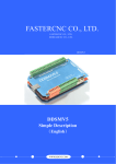
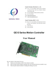
请在这里输入您的公司名称 FASTERCNC CO., LTD. FASTERCNC CO., LTD. DDREAMCNC CO., LTD. DDMDLV1 DDMDLV1 Simple Description (English) WWW.DDCNC.COM M WWW.DDCNC.COM DDMDLV1 MACH3 CARD Contents Chapter 1 1.1 1.2 1.3 1.4 1.5 Chapter 2 2.1 2.2 Chapter 3 3.1 3.2 3.3 Chapter 4 4.1 4.2 Chapter 5 5.1 5.2 Overview .............................................................................................................................................. 1 Simply Introduction ................................................................................................................................ 1 Requirements of Computer ..................................................................................................................... 1 Product feature........................................................................................................................................ 2 Outview & Size....................................................................................................................................... 3 Notes and Cautions ................................................................................................................................. 6 Detail Features ..................................................................................................................................... 7 Electrical parameters............................................................................................................................... 7 Functions and define of each module ..................................................................................................... 8 Software Installation ........................................................................................................................ 17 MACH3 Install ..................................................................................................................................... 17 MACH3 Registration ............................................................................................................................ 20 USB Plug-in installation ....................................................................................................................... 20 Software ............................................................................................................................................. 21 Open Software ...................................................................................................................................... 21 Software Common settings ................................................................................................................... 22 Q&A................................................................................................................................................. 28 Q & A.................................................................................................................................................... 28 Contact us ............................................................................................................................................. 28 Chapter 01 Overview WWW.DDCNC.COM Chapter 1 Overview 1.1 Simply Introduction DDMDLV1.0 is designed by our Studio, it is a CNC system based mach3.It’s version is 1.0 now. You do not need to add other Hardware,and you can complete the signal conversion from the G-code to the movement of the stepper motor drive control. This card is compatible with most stepper motor with 0.6-4A and 2-phase. And it is perfect weapon to replace mach3 parallel interface stepper driver board. 1.2 Requirements of Computer Basic Configuration: 1) CPU:1GHz; 2) Memory:512MB 3) 500MB Available disk space 4) USB 2.0 Recommended configuration: 1) CPU:2GHz Dual Core; 2) Memory:2GB; 3) 1G Available disk space 4) USB 2.0 1 Chapter 01 Overview WWW.DDCNC.COM 1.3 Product feature 1) USB communication interface, and power supply for the board; 2) 11 IO input, opto-isolated, It Can be configured to limit the emergency stop and other functions, all of them are 15D-3.5 port. 3) 6 IO input with no opto-isolated but with iso-IC. This port is set to 15D-3.5mm and PHB2.0-2*3port. 4) 2 IO output with opto-isolated for spindle can be configured to EN and DIR. 5) up to 5 axes stepper-motor control port. Each port has up to 200KHz plus output; 6) COTEX-M3 of NXP-LPC is main control chip; New feature 7) New design Aluminum cooling make the system more stable; 8) This system is equipped with RS2332 manual control box. You can use manual control box with this port. 9) Equip control panel. You can give normal order from this panel on box. 10) Spindle control port has PWM Mod(0%-100% dutycycle with 12Vpp)and voltage Mod(0-10V). 11) Spindle speed feed back port-INDEX. 12) There is a power autostability system. When USB port overvoltage or undervoltage or within other EMI, this system can make power of system stable. 13) There are High speed interface chips,which make stepper driver signal more stable. 14) There is a USB protection chip,which can protect system within high voltage EMI; 2 Chapter 01 Overview WWW.DDCNC.COM 1.4 Outview & Size Figure1-1. Size of DDMDLV1.0 Figure1-2. Install Size of DDMDLV1.0 3 Chapter 01 Overview WWW.DDCNC.COM Figure1-3. Outview of DDMDLV1.0 Figure1-4. Outview of DDMDLV1.0 4 Chapter 01 Overview WWW.DDCNC.COM Figure1-5. Outview of DDMDLV1.0 5 Chapter 01 Overview WWW.DDCNC.COM Figure1-6. Outview of DDMDLV1.0 1.5 Notes and Cautions Prohibits the rain, boards for high-performance precision equipment, rain can cause short-circuit CAUTION WARNING, various wiring in strict accordance with installation Description document specification. High risk, boards need to stay away from high-pressure. 6 Chapter 02 Detail Feature WWW.DDCNC.COM Chapter 2 Detail Features 2.1 Electrical parameters A. System input voltage5V; B. Operating voltage of input interface with no opto-isolated:5V C. Operating voltage of input interface with opto-isolated:12V; D. Operating voltage of output interface:5V; E. stepper motor control signal output voltage:5V; F. Spindle Signal:10V; 7 Chapter 02 Detail Feature WWW.DDCNC.COM 2.2 Functions and define of each module Figure2-1. Block of Function ■ A)USB PORT,This interface is connected to the computer through a USB line. You can use the software mach3 to control this board, Note that you should use a USB2.0 cable with shielding and ferrite core, and cable length should be not more than 2 meters. ■ B) ※Power supply system. The 5V power from PC has interference in complex electromagnetic environment eg. Stepper motor and spindle motor. The power supply from 3V-7V can be limited to 5V±10% and 3.3V±10% by this power supply system. 8 Chapter 02 Detail Feature WWW.DDCNC.COM ■ C)Control panel port. See as Figure 2-2, This port can conjunct with Control panel. This port is a double row port of 2.54mm pin spacing. Figure2-2. Control panel ■ D) These four blue potentiometer mange XYZA 4axis steppe rmotors’ decay. The end of clockwise is fast decay. And the end of counter-clockwise is slow decay. Adjust them according the motors’ need. ■ E) These four blue potentiometer mange XYZA 4axis steppe rmotors’ current. Turn clockwise will increase the current, and turn counter-clockwise will decrease the current. Please adjust them according the motors’ need. The position of current see as Figure 2-3. Figure2-3. Position of current ■ F) These four green 4P port are XYZA 4axis stepper motor port. Each port’s definition is A+ A- B+ B- from down to up. Wiring method see as figure 2-4. 9 Chapter 02 Detail Feature WWW.DDCNC.COM Figure2-4. Wiring with stepper motor ■ G)These 4 blue slide switch . microstep Step/circle SW1 SW2 SW3 2 400 OFF OFF OFF 8 1600 ON OFF OFF 16 3200 OFF ON OFF 32 6400 ON ON OFF 64 12800 OFF OFF ON 128 25600 ON OFF ON 10 2000 OFF ON ON 20 4000 ON ON ON Form 2-1 The form of micorstep definition ■ H) See as figure2-1, these 4 LED belong to XYZA 4 axis form up to down. When one axis stepper motor run , eg. X axis, the LED will be on when the stepper motor stop, the LED will be off. 10 Chapter 02 Detail Feature WWW.DDCNC.COM ■ J).12V power supply. You can conjunct a 12V fan or other 12V equipment to this port. The maximum current is 500mA. ■ K)Spindle port. This port doesn’t need reference voltage. It can supply a speed regulating voltage to Frequency Converter. It is defined as EG/DIR/EN/0V/PWM/VE from left to right. EG is a spindle speed feedback signal. DIR is direction signal output. EN is enable signal output. 0V is ground Pin. PWM is pulse-width modulation signal output. VE is voltage signal output. Wiring with Frequency Converter see as Figure2-5.VE to VI as a speed conjuncting port. DIR/EN to M1/M2, can be set as RUN/STOP or other function. Wiring with Brushless DC driver see as figure 2-6. The definitions of this port and BLDC driver are the same. You can conjunct them together by difiniton. Attention, DIR/EN is defined as PIN6/7 of PORT2# in mach3. 11 Chapter 02 Detail Feature WWW.DDCNC.COM Figure2-5. Wiring with Frequency Converter 12 Chapter 02 Detail Feature WWW.DDCNC.COM Figure2-6. Wiring with BLDC driver ■ L) Power input. This card support AC and DC power input. AC power support AC12V-AC28V \50Hz\8A. DC power support DC15V-45V 10A. DC input definition is + - from left to right. ■ M) Output port without opticalcoupler. This port has no opticalcoupler,but there are another opto-isolated IC. If there are high voltage input,it can protect the board. The maximum current supply is 20mA. This port is defined as GND/OUT1/OUT2/5V from left to right. OUT1/2 is PIN1 and PIN2 of PORT2# in mach3. ■ N)Hand control box/HMI port. This is a UART port. Hand control box and HMI can 13 Chapter 02 Detail Feature WWW.DDCNC.COM connect to mach3 from this port. See as Figure 2-7 Figure2-7. Index port connection method ■ O)B axis control signal port. This port is B axis control signal port. It can connect to B axis stepper motor driver. Definition see as Figure 2-8.Common anode. COM+ connect to STEP+ and DIR+ of driver, CP- connect to STEP- of driver, DIR- connect to DIR- of river. Figure2-8. B axis’ definition ■ P)Estop and probe .This port is 15D-3.5-3P port. Pin distance is 3.5mm. It’s defined as ESTOP/PROBE/12V from left to right, see as figure 2-9. ESTOP and PROBE are 14 Chapter 02 Detail Feature WWW.DDCNC.COM defined as PIN1 and PIN2 of PORT1# in mach3. Figure2-9. Wiring of estop and probe ■ Q) Common input with optocoupler. It’s defined as 12V/IN3/IN4/IN5/IN6/IN7/IN8/IN9/IN10/0V from left to right. They are PIN3/4/5/6/7/8/9/10 of PORT1# in mach3. 2-wire proximity switch and microswitch wiring method see as figure 2-10. 3-wire PNP proximity switch wiring method see as figure 2-11. 15 Chapter 02 Detail Feature WWW.DDCNC.COM Figure2-10. Figure2-11. microswitch wiring method 3-wire PNP proximity switch wiring method ■ R)Common IO output. PHB-2.0 special port. This port supply only 2mA current. If you want connect this port to optocoupler, you should boost the current. This port can connect to 4-relay board from our company. The definition of this port see as figure 2-12. special output port Figure2-12. 16 Chapter 03 Software installation WWW.DDCNC.COM Chapter 3 Software Installation 3.1 MACH3 Install When you purchase our product, we will supply a CD-ROM, which contains the MACH3 installation, registration, and USB plug-ins. See as Figure 3-1. Figure3-1. software of CD-ROM First run the installation Mach3Version3.043.066 first page. See as Figure 3-2. 17 。Into the Chapter 03 Software installation WWW.DDCNC.COM Figure3-2. MACH3 installation process 1 Click Next and then enter the page shown in Figure 3-3 Figure3-3. installation process 2 选择同意协议,点下一步,如图 3-4 18 Chapter 03 Software installation WWW.DDCNC.COM Figure3-4. MACH3 installation process 3 Select the installation path, click Next (it can be installed on any disk, and recommended to install the C drive or the D drive) See as Figure 3-5 Figure3-5. MACH3 installation process 4 Click Next until completion. Then restart the computer. 19 Chapter 03 Software installation WWW.DDCNC.COM 3.2 MACH3 Registration Copy the file Mach1Lic.dat in The CD-ROM to mach3 installation path (eg C:/MACH3). 3.3 USB Plug-in installation Copy the file DDSM.dll to X:\Mach3\PlugIns,X is the disk where the soft is installed. 20 Chapter 04 Software WWW.DDCNC.COM Chapter 4 Software 4.1 Open Software ■ Double-click the mach3mill 。 Enter mach3 software. Pop-up the plug-in dialog box. See as Figure 4-1. Figure4-1. Plugin selection dialog Choose our plugin DDSM-USBMACH3-PlugIn---Ver-2.0a。Then press OK. If you do not want to the dialog box appear again next time, you can select Don’t ask me this again. 21 Chapter 04 Software WWW.DDCNC.COM 4.2 Software Common settings ■ DDSM plugin setting Figure4-2. get in config plugins Figure4-3. click config of DDMD 22 Chapter 04 Software WWW.DDCNC.COM Figure4-4. config dialog In this dialog you can change buffer time. Suggest setting is device buffer to 400ms and jog buffer to 100ms.If your system is not stable, pls increase device buffer time. ■ Motor operating parameters setting Figure4-5. Motor operating parameter setting menu entry See as Figure 4-5.From submenu “motor tuning” of the menu “config” into the motor parameter settings dialog. See as Figure 4-6 Figure4-6. Motor operating parameter settings dialog 23 Chapter 04 Software WWW.DDCNC.COM The parameters are defined as follows: Steps per:Pulse equivalent ,it is number of pulses required with axial movement 1mm, This can be calculated by lead screw pitch and motor drive segment. Such as pitch 2.5mm,2-phase motor 8 segments, Calculation method is 8*200/2.5=640。 Velocity:The speed is the axial velocity, Units is mm/s,Recommended settings 1500. Acceleration:Units is mm/s2,Recommended settings 200. Step Pulse:Step Pulse Cannot be set, it’s 2.5us in default. Dir Pulse:. Dir Pulse Cannot be set, it’s 2.5us in default. Attention: The parameters for each axis is not necessarily the same,To select the axis, and then set parameters. You should click “SAVE AXIS SETTINGS” After setting. ■ Port Settings Figure4-7. Port setting intry See as Figure 4-7,Click the sub-menu “ports and pins” of menu “Config” into Port Settings dialog box. Figure4-8. Pin&Port Dialog 24 Chapter 04 Software WWW.DDCNC.COM The sub-pages you need to set include “Motor Outputs”, “Input Signals”, “Output Signals” and “Spindle Setup”.First Click to enter “Motor Outputs”. This page is to select the stepper motor control pin. Because our usbmach3 interface board stepper motor signals are fixed, So here only need to Select, no need to select the specific pin. See as Figure4-9 To make the Z axis to the same direction, Z axis’s “Dir low” should be set to”√”.Other axes’s should be set as system need. Figure4-9. Stepper motor port settings dialog Click “Input Signals” Into the input signal settings page. See as Figure4-10 25 Chapter 04 Software WWW.DDCNC.COM IO limited Input Settings dialog Here you can configure according to your actual needs the corresponding function. Optional Function include XYZABC6axis’s Upper and lower limit、XYZABC6axis’s HOME point. Figure4-10. Figure4-11. Estop Probe and index Setting dialog PROBE、ESTOP and Spindle speed back index Setting see as Figure 4-11,PIN of index should be set to 0,and probe’s pin number is 2,estop’s pin number is 1. Click “Output Signals” to enter the Output signal setting page. See as Figure 4-12 26 Chapter 04 Software WWW.DDCNC.COM Figure4-12. Output Signal Setup dialog Note that the output signal number from 1-9. Because there is an overlap with the input signal, We set output signals to the port 2.See as Figure4-12, PORT # All output signal is set to 2.Please put Output signal to the corresponding options as you need. Here OUT1\2 is 15D-3.5 common port;OUT3 is EN of XYZA stepper motor; OUT4\5\6\7 is special port; OUT8\9 is EN and DIR signal for spindle. Click “Spindle Setup” switch to the spindle settings page. See as Figure4-13 Spindle Settings dialog Here we can configure the spindle rotates CW、Reverse CCW、Mist、Flood pin, See as Figure4-13,They have been configured as 1、2、3、4. Corresponding to output#1~output#4 in Figure4-14.output#1~output#6 in Output Signal Setup dialog can be Configured into these 4 signals. Here we note correspondence between 2 page. Please select “use spindle motor output” if required PWM speed spindle. And select “ PWM Control”. Our PWM pin fixedly arranged on a special pin, it’s no need to be set Figure4-13. 27 Chapter 05 Q & A WWW.DDCNC.COM Chapter 5 Q&A 5.1 Q & A 5.2 Contact us Company Website:ddcnc.com; Technical Support email:[email protected]; Technical Support qq:649631655; 28


