1
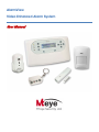
AlarmView
Video Enhanced Alarm System
User Manual
Table of Contents
TABLE OF CONTENTS
1
Introduction .......................................................................................... 4
1.1 General............................................................................................................ 4
1.2 Documentation Graphic Conventions ............................................................. 6
1.3 Glossary of Terms ............................................................................................. 6
2
Quick Reference Guide .................................................................... 10
2.1 System Components...................................................................................... 10
2.1.1
2.1.2
2.1.3
2.1.4
2.1.5
2.1.6
2.2
2.3
2.4
2.5
2.6
2.7
3
Media Gateway ..........................................................................................................10
Video Zone Sensors .....................................................................................................10
Wireless Sensors ...........................................................................................................11
Sirens ...........................................................................................................................11
Keyfobs / Remote Controls .........................................................................................11
Panic / Medical Alarm - Pendant / Wrist Watch ..........................................................11
Media Gateway Component Overview ......................................................... 12
Media Gateway Key Definition ....................................................................... 13
Main LCD Display ........................................................................................... 14
Sound Indicators ............................................................................................ 14
LED Indicators................................................................................................. 15
Viewing the System Status .............................................................................. 15
Operating Instructions ....................................................................... 17
3.1 Arming Options and Behavior......................................................................... 17
3.1.1
3.1.2
3.1.3
3.1.4
3.1.5
Away Arming ...............................................................................................................17
Home Arming ..............................................................................................................18
Partial Arming ..............................................................................................................18
Forced Arming ............................................................................................................18
Disarming ....................................................................................................................18
3.2 Controlling the System Using a Keyfob............................................................ 19
3.3 Controlling the System Using an external wireless Keypad .............................. 19
3.4 Controlling the System via Cellular Phone....................................................... 19
3.4.1
3.4.2
Overview .....................................................................................................................19
Cellular Phone Commands ........................................................................................20
3.4.2.1
3.4.3
4
Miscellaneous Cellular Commands ........................................................................... 21
Cellular Messages .......................................................................................................21
System Menus .................................................................................... 22
4.1 Overview ........................................................................................................ 22
4.2 Accessing the Various Menus ......................................................................... 22
4.3 Options Menu ................................................................................................ 23
4.3.1
4.3.2
4.3.3
Global Settings ............................................................................................................23
Zone Bypass ................................................................................................................23
User Account Disable ..................................................................................................24
4.4 Event Log Menu ............................................................................................. 25
4.5 Service Menu ................................................................................................. 25
4.5.1
Performing System Tests ..............................................................................................26
4.5.1.1
4.5.1.2
4.5.1.3
4.5.1.4
Page I
Zones ................................................................................................................................. 26
External Siren.................................................................................................................... 26
Internal Siren Test ............................................................................................................ 28
Communication Test...................................................................................................... 28
AlarmView Installation and User Manual
Table of Contents
4.5.1.5
4.5.2
4.5.3
4.5.4
Self Test.............................................................................................................................. 30
Enabling Programming ...............................................................................................30
Displaying System Version ...........................................................................................30
Performing a System Reset .........................................................................................31
4.6 Passwords Menu............................................................................................. 31
4.6.1
4.6.2
4.6.3
4.6.4
4.6.5
User Codes ..................................................................................................................32
Master User ..................................................................................................................33
Duress Code ...............................................................................................................33
Time (24H) limited Code .............................................................................................34
Installer ........................................................................................................................35
4.7 Set Clock Menu .............................................................................................. 36
4.8 Stop Communication Menu........................................................................... 37
Appendix A
Maintenance & Troubleshooting .................................... 38
A.1 Cleaning the Media Gateway........................................................................ 38
A.2 Replacing the Media Gateway Battery .......................................................... 38
A.3 Replacing the SmartView Battery .................................................................... 39
Appendix B
Menu Map ........................................................................ 41
Appendix C
Useful Tables ..................................................................... 42
C.1
C.2
C.3
C.4
Sensor Placement .......................................................................................... 42
Keyfob / Remote Control Owners ................................................................... 43
Emergency Devices ....................................................................................... 43
Alarm Messages............................................................................................. 43
Appendix D
Remote Command Tables .............................................. 45
Appendix E
Warranty ........................................................................... 46
Appendix F
Declaration of Conformity .............................................. 47
AlarmView Installation and User Manual
Page II
Notice and Disclaimer
NOTICE AND DISCLAIMER
THIS MANUAL IS INTENDED TO ASSIST INSTALLERS AND OPERATORS IN THE SAFE AND
EFFICIENT INSTALLATION AND USE OF THE SYSTEM DESCRIBED HEREIN.
BEFORE ATTEMPTING TO INSTALL AND USE THE SYSTEM, THE INSTALLER / USER MUST
READ THIS MANUAL AND BECOME FAMILIAR WITH ALL SAFETY REQUIREMENTS AND
OPERATING PROCEDURES.
THE SYSTEM MUST NOT BE USED FOR PURPOSES OTHER THAN THOSE FOR WHICH IT
WAS DESIGNED.
THE USE OF THE SOFTWARE ASSOCIATED WITH THE SYSTEM IS SUBJECT TO THE
TERMS OF THE LICENSE PROVIDED AS PART OF THE PURCHASE DOCUMENTS.
MTEYE SECURITY LTD.’S EXCLUSIVE WARRANTY AND LIABILITY IS LIMITED TO THE
WARRANTY AND LIABILITY STATEMENT PROVIDED IN AN APPENDIX AT THE END OF THIS
DOCUMENT.
THIS MANUAL DESCRIBES THE MAXIMUM CONFIGURATION OF THE SYSTEM WITH THE
MAXIMUM NUMBER OF FUNCTIONS, INCLUDING FUTURE OPTIONS. THEREFORE, NOT
ALL FUNCTIONS DESCRIBED IN THIS MANUAL MAY BE AVAILABLE IN A SPECIFIC SYSTEM.
WARNINGS ARE GIVEN FOR SITUATIONS AND CIRCUMSTANCES IN WHICH A POSSIBLE
HAZARD CAN ARISE.
CAUTIONS ARE GIVEN FOR SITUATIONS OR CIRCUMSTANCES IN WHICH THE SYSTEM
CAN POSSIBLY BE DAMAGED.
NOTES ARE GIVEN FOR SITUATIONS REQUIRING SPECIAL ATTENTION OR TO IMPROVE
THE OPERATING PROCEDURE.
INCORRECT OPERATION, OR FAILURE OF THE OPERATOR TO EFFECTIVELY MAINTAIN
THE SYSTEM, RELIEVES THE MANUFACTURER (AND SELLER) FROM ALL OR ANY
RESPONSIBILITY FOR CONSEQUENT NONCOMPLIANCE, DAMAGE, OR INJURY.
THE TEXT AND GRAPHICS CONTAINED IN THE MANUAL ARE FOR THE PURPOSE OF
ILLUSTRATION AND REFERENCE ONLY. IN NO EVENT SHALL MANUFACTURER BE LIABLE
FOR ANY SPECIAL, DIRECT, INDIRECT, INCIDENTAL, CONSEQUENTIAL, EXEMPLARY OR
PUNITIVE DAMAGES (INCLUDING, WITHOUT LIMITATION, ANY AND ALL DAMAGES FROM
BUSINESS INTERRUPTION, LOSS OF PROFITS OR REVENUE, COST OF CAPITAL OR LOSS
OF USE OF ANY PROPERTY OR CAPITAL OR INJURY).
COPYRIGHT ׃2009 BY MTEYE SECURITY LTD. ALL RIGHTS RESERVED.
THIS MANUAL AND THE INFORMATION CONTAINED HEREIN ARE PROPRIETARY TO MTEYE
SECURITY LTD. ONLY MTEYE SECURITY LTD. OR ITS CUSTOMERS HAVE THE RIGHT TO USE
THE INFORMATION.
NO PART OF THIS MANUAL MAY BE RE-PRODUCED OR TRANSMITTED IN ANY FORM OR BY ANY
MEANS, ELECTRONIC OR MECHANICAL, FOR ANY PURPOSE, WITHOUT THE EXPRESS WRITTEN
PERMISSION OF MTEYE SECURITY LTD.
MTEYE SECURITY LTD. OWNS PATENTS AND PATENT APPLICATIONS, TRADEMARKS,
COPYRIGHTS, OR OTHER INTELLECTUAL PROPERTY RIGHTS COVERING THE SUBJECT MATTER
IN THIS MANUAL.
THE FURNISHING OF THIS MANUAL TO ANY PARTY DOES NOT GIVE THAT PARTY OR ANY THIRD
PARTY ANY LICENSE TO THESE PATENTS, TRADEMARKS, COPYRIGHTS OR OTHER
INTELLECTUAL PROPERTY RIGHTS, EXCEPT AS EXPRESSLY PROVIDED IN ANY WRITTEN
AGREEMENT OF MTEYE SECURITY LTD.
Page III
AlarmView Installation and User Manual
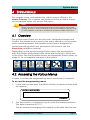
Introduction
1 INTRODUCTION
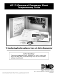
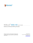
This manual is designed to assist the user with the operation of the
AlarmView Video enhanced alarm system.
1.1 General
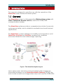
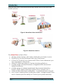
The AlarmView system is a 3rd generation Wireless Alarm system with
Video-Verification, Remote-Look-In, and built-in GPRS/GSM
communication modem.
The AlarmView system provides a comprehensive solution for security
and personal safety, and is suitable for residential and small business
applications.
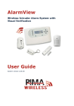
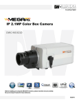
The AlarmView’s unique offering is in its ability to incorporate a set of
SmartView, LiveView and OutView cameras that combines
movement detection and video/image capturing.
Figure 1 The AlarmView System Layout
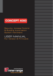
Upon alarm event, both the event and related video images are
transmitted wirelessly to the AlarmView Media Gateway (MGW); the
event code as well as an image/video-clip is sent over the GPRS/GSM
AlarmView Installation and User Manual
Page 4
Introduction
network directly to the alarm receiving center and or the end-user
mobile phone.
Figure 2 AlarmView Video Verification
Figure 3 AlarmView Look-In
The AlarmView system offers:
•
•
•
•
•
•
•
•
Wireless Alarm System with Video-Verification & Video Look-In
Security for your environment and your loved ones
A View & Control of your Home and Office, from whereever you
are, anywhere in the world
Alarm & Video reporting to Central Monitoring Stations
A wide range of Smart cameras, integrated with movement
detection sensors
A Wide range of wireless peripherals (Movement detection,
Smoke, Panic alarm, Remote controls, Door contact, etc.)
Video & Alarm End-user notification – to mobile phones or email
Use of your mobile phone for Remote video / image request from
each camera plus the ability to Control your system remotely
Page 5
AlarmView Installation and User Manual
Introduction
1.2 Documentation Graphic Conventions
Familiarize yourself with these icons and conventions to make better
use of the manual as you read through it.
Note
Important notes used to emphasize points, also
used for useful operation tips
Used to indicate issues that may cause system
malfunctions
Caution
Warning
Used to indicate issues that may cause
damage to the system or actual bodily harm
Indicates menus accessed by the master user
Master User
Indicates menus accessed by the installer
Installer
Remote Access
Indicates menus accessed remotely, usually by
Monitoring Station or Service Center
1.3 Glossary of Terms
•
Alarms – A signal that warns or calls to action, based on the type
defined below
o Burglary Alarm – An alarm caused by a violation of one or
more of the intrusion zones.
o Fire Alarm – An alarm initiated due to a violation of one or
more of the fire zones (heat, smoke detectors).
o Tamper Alarm – An alarm caused by an open tamper
protection, for example when someone attempts to remove
a sensor or the Media Gateway from the wall.
o Panic/Medical/Emergency Alarm – An alarm due to an
activation of a panic / distress button or medical sensor.
o Alarm Restore – Closes the alarm event and restores the
system to its previous state.
•
Arming – Activation of the alarm system
o Arming Modes:
Away – Full arming of the system, best used when there is
no one at home/office.
AlarmView Installation and User Manual
Page 6
Introduction
Home – Home arming is a perimeter arming of all
perimeter sensors and detectors as defined by the installer.
For use when home/office is occupied.
Partial – Partial arming is designed for when you wish to
secure one part of the premises while leaving the other
part unsecured.
o One-Key Arming – Allows arming the system using a single key
without the use of a code.
o Force Arming – Allows you to arm the system even if the
system is not ready, under the condition that all open zones
will be closed by the end of the Exit delay. If the zone/s is
open when the exit delay expires, an alarm is generated.
•
•
Chime – "Ding-Dong" Bell sound typically assigned to an entry
point or back door to indicate entry when the system is
disarmed.
Contacts – are the system's destinations/people that receive the
events reporting described above as well as perform some predefined authorized tasks.
o User Contact –Private users, usually the owner of the system or
other family members.
o CMS Contact – Central Monitoring Station or as sometimes
described: Alarm Receiving Centers.
•
•
•
Disarmed – System is in normal standby mode. Only 24 hour zones
are active (Panic, Fire, Tamper, etc.)
Entry/Exit Delay – The predetermined time set before triggering
an alarm. Associated with the entry/exit zones defined above.
Events – an occurrence of significant in the system reported to
either the user or/and the monitoring center.
o Alarm events – an occurrence relating to an alarm triggered
or deactivated within the system.
o Arming events – an occurrence relating to arming or
disarming of the system.
o Video events – an occurrence of an event sent together with
still images or a video clip for verification.
o Event Groups – a group of events defined by type, which
allows you to define the type of events for which you would
like to receive notifications.
•
Media Gateway – The control panel where the user can activate
/ deactivate the alarm as well as change the various system
configurations. This is the heart and brains of the system which
also includes the system’s communication module.
Page 7
AlarmView Installation and User Manual
Introduction
•
Sensors/Devices/Peripherals:
o Device ID – A unique identification of the sensor (serial
number).
o Device types:
•
•
SmartView – MTEye’s video enhanced PIR detector,
PIR – Passive infrared detector – Apparent motion is
detected when there is a movement of humans or animals
within the protected area; detection is based on the heat
emission of humans.
Door Contact – A detector comprising a magnetically
operated reed switch and a separate magnet. Usually
used on doors and windows to detect whether the door or
window is opened or closed.
Keyfob – A small remote control that can be used to
arm/disarm the system.
Smoke Detector – A sensing device which detects smoke
or visible or invisible particles of combustion
Panic button – A button that triggers an alarm, setting off a
precipitous emergency response.
System Ready – System is ready for arming – all zones that are
part of the defined arming mode are closed.
Users – This shows the various users defined in the system and their
permissions.
o Regular User – can arm/disarm the system and view the
system’s general status.
o Master User – normally the owner of the system/protected
premises. Can arm/disarm, change settings relating to the
system behavior, as well as setting/changing authorized
passwords.
o Installer – normally a professional installer of intrusion systems,
authorized to define and perform changes to the system’s
parameters. Installer access requires the Master User’s
permission.
•
Zones - A protected area; connected with a detection device
(sensor), dependant on the protected area type (see Zone Types
ahead) (e.g. zone #1 = “Front Door”, zone #2 = “Living Room
Motion”, Zone #3 = “Smoke Detector” etc.)
o Regular Zones - Protection zones of various sorts including
intrusion, fire, distress medical etc.
o Video Zones – Protection zones using a detector (usually
motion) combined with a stills or video camera used for alarm
verification and/or Look-in.
AlarmView Installation and User Manual
Page 8
Introduction
o Zone Types:
•
Normal (Immediate) – Burglary Protection zone; Activates
an alarm immediately upon system arming.
Entry/Exit – Burglary Protection zone; Zones that are in the
premises’ entry/exit route. A delay can be defined to
allow entry/exit before system arming.
Follower – This zone type behaves as a normal zone in the
event of intrusion, however if an entry/exit zone was
opened it will follow it, meaning it will wait for the delay to
be over before initiating the alarm. This zone type is
typically used in the entry/exit route but also protects an
additional entry point such as an outside window.
24Hr – A zone which is protected always, even when the
system is disarmed. Typically used together with a tamper
protection or similar device.
Panic – used with permanent distress/panic buttons.
Medical – sensors or distress/panic buttons used in the
event of a medical emergency.
Fire – A zone used in conjunction with heat and smoke
detectors.
Zone Bypass / Un-bypass - To temporarily de-activate a zone /
sensor, so as not to trigger the alarm system while armed. This
feature is usually used when a sensor is defective, or a window is
intentionally left open
Page 9
AlarmView Installation and User Manual
Quick Reference Guide
2 QUICK REFERENCE GUIDE
Use this quick reference to better familiarize yourself with the system.
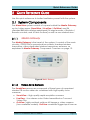
2.1 System Components
The AlarmView system consists of a panel called the Media Gateway,
up to 6 video zones (SmartView / LiveView / OutView) and 36
standard 868 MHz wireless peripherals (24 regular zones, 6 Keyfobs /
Remote controls, and 6 Panic buttons) as well as one wireless siren.
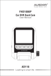
2.1.1
Media Gateway
The Media Gateway is the heart of the system; it consists of the main
circuitry, GPRS/GSM communication module, standard wireless
transceiver, video-dedicated wireless transceiver, antenna, as
explained in Media Gateway Component Overview on page 12.
Figure 4 Media Gateway
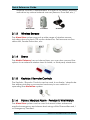
2.1.2
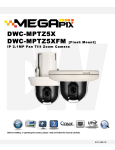
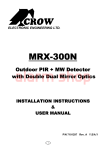
Video Zone Sensors
The SmartView sensors are composed of three types of supervised
wireless PIR motion detector combined with high-quality color
cameras:
•
•
•
SmartView – High quality rapid acquisition camera.
LiveView – Live stream color Video transmitted as 7 second
Video-Clip.
OutView- highly resistant outdoor still image or video camera
(two available models). OutView combines Trigger Input from an
AlarmView Installation and User Manual
Page 10
Quick Reference Guide
external sources, in replacement to a built-in PIR sensor, allowing
activation by various external sources (Sensors, Door Bell, etc.)
SmartView
2.1.3
LiveView
OutView
Wireless Sensors
The AlarmView system supports a wide range of wireless sensors,
including door contacts, PIR motion detectors, Pet-Immune motion
detectors, Smoke Detectors, etc.
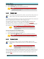
2.1.4
Sirens
The Media Gateway has an internal siren; you can also connect the
system to an external wireless siren & strobe, or third party wired siren.
2.1.5
Keyfobs / Remote Controls
The Keyfobs / Remote Controls can be used to activate / deactivate
the alarm providing a convenient and easy to use method of
operating the AlarmView system.
2.1.6
Panic / Medical Alarm - Pendant / Wrist Watch
The AlarmView system can be used to transmit video enhanced
medical emergency and duress alerts using a Wrist Transmitter and /
or Emergency Pendant.
Page 11
AlarmView Installation and User Manual
Quick Reference Guide
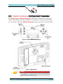
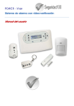
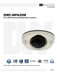
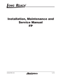
2.2 Media Gateway Component Overview
The AlarmView’s Media Gateway is the main interface to be used
when operating the alarm system. This section comes to familiarize
you, the user, with the Media Gateway panel and all its functionality.
Figure 5 Front Panel action keys
Figure 6 Back Panel
Note:
The Tamper is an order option and is only available if
specified in the original order.
AlarmView Installation and User Manual
Page 12
Quick Reference Guide
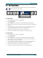
2.3 Media Gateway Key Definition
The table below details the Media Gateway’s key definition and
functions
Arming keys
Away
Arm Away (full Arm)
Home
Arm Home (perimeter)
Partial
Partial Arming
Soft keys
Left
Access Menu, Select and Insert functions
Right
View Status, Cancel and Delete functions
Navigation keys
Page 13
OK
Input confirmation
Up
Scroll Up, Password numeric key 1, Scroll
Alphanumeric values (A-Z, 0-9)
Down
Scroll Down, Password numeric key 3, Scroll
Alphanumeric values (A-Z, 0-9)
Left
Access and scroll left, Password numeric key 4
Right
Access and scroll right, Password numeric key 1
AlarmView Installation and User Manual
Quick Reference Guide
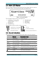
2.4 Main LCD Display
The LCD screen shows at any given time the system status as well as
the current time, GSM service provider and signal level.
AlarmView
VODAFONE
12 : 00 : 00
D ISARM
MENU
INFO
Figure 7 LCD main Display
The available system status messages are:
Initializing – Shown after
• Armed Home
initial startup or after a
• Armed Part
system reset.
• Exit Delay
• Disarmed
• Entry Delay
• Armed Away
The available system trouble status icons are:
•
Transmission of message
AC Loss
GSM Reception Level
Low Backup Battery
GSM Network Error
Communication Buffer Full
2.5 Sound Indicators
Following are the sounds emitted by the system and the keypad:
Sound
Sounded when
♪
Single Beep
A key is pressed
♪-♪
Two Short Beeps
A Menu Timeout occurs – Exits to Main
Menu
♪-♪-♪
Three Short Beeps
A Command / Operation is Successful
♪-♪-♪-♪
Four Short Beeps
The system is in Trouble Condition (will
repeat every minute)
♪-♪-♪-♪…
Continuous short
beeps
The system is in Entry / Exit delay mode
♪♪♪♪♪
Long Beep
Illegal Command or Entry refusal
Chime
The Chime is activated
AlarmView Installation and User Manual
Page 14
Quick Reference Guide
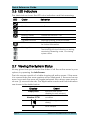
2.6 LED Indicators
The table below shows the LED color indicators and their meaning.
LED
Color
Behavior
GREEN
Power – OK
BLANK
No Power
Blinking BLUE
Wireless communication is active
Blinking GREEN
Cellular connection – OK
Blinking YELLOW
Cellular connection – No Network
3 Flashes YELLOW
Message waiting to be processed
RED
Indicates System Trouble, see LCD display
for further information
Blinking White
Alarm triggered.
The blinking will stop following re-arming,
reentering disarming code, or entering
system menu
2.7 Viewing the System Status
At any given time you can see the status of all the active zones in your
system, by opening the Info Screen.
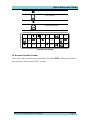
The info screen consists of a table showing all active zones. If the zone
is in normal state the zone number will be displayed, if the zone has an
event or events the zone will toggle between the various open events
at one (1) second intervals. The applicable events and their indication
are shown in the table below:
Display
Empty Field
Unblinking
Number 01-30
Event
Inactive Zone (zone
disabled or non-existent)
Active Zone – Normal
condition
Open Zone (system not
ready)
T
Page 15
Zone Tamper
AlarmView Installation and User Manual
Quick Reference Guide
Bypassed Zone
B
Low Battery
Supervision Loss
X
Alarm Message
1
2
12
X
T
B
5
X
T
23
10
6
17
B
27
30
Figure 8 Info Screen
To Access the Info Screen:
From the main screen press the Right Soft Key INFO. Pressing either of
the soft keys will exit the INFO screen.
AlarmView Installation and User Manual
Page 16
Operating Instructions
3 OPERATING INSTRUCTIONS
This chapter comes to explain all operation aspects of the AlarmView.
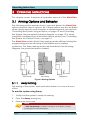
3.1 Arming Options and Behavior
The following section explains how to arm and disarm the AlarmView
system using the various options. All of these options are also available
when using a remote control keyfob or wireless keypads, see sections
Controlling the System Using a Keyfob, on page 19 and Controlling
the System Using an external wireless Keypad, on page 19 or when
using SMS command from authorized cellular phones, see Controlling
the System via Cellular Phone, on page 19.
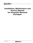
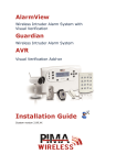
The AlarmView system allows three arming modes defined during the
programming process allowing a fully flexible and complete
protection. The three arming modes are illustrated in the following
diagram, the protected area is shaded.
Figure 9 Arming Options
3.1.1
Away Arming
Full arming of the system, best used when there is no one at home /
office.
To arm the system using Away:
1.
Verify that the system is ready for arming.
2.
Press the Away arming key.
3.
Enter your user code.
Note:
If One Key Arming is enabled, arming is activated by simply
pressing the Away arming key.
Page 17
AlarmView Installation and User Manual
Operating Instructions
3.1.2
Home Arming
Home arming is a perimeter arming of all perimeter sensors and
detectors as defined by the installer. For use when home / office is
occupied.
To arm the system using Home:
1.
Verify that the system is ready for arming.
2.
Press the Home arming key.
3.
Enter your user code.
Note:
If One Key Arming is enabled, arming is activated by simply
pressing the Home arming key.
3.1.3
Partial Arming
Partial arming is designed for when you wish to secure one part of the
premises while leaving the other part unsecured.
To arm the system using Partial:
1.
Verify that the system is ready for arming.
2.
Press the Partial arming key.
3.
Enter your user code.
Note:
If One Key Arming is enabled, arming is activated by simply
pressing the Partial arming key.
3.1.4
Forced Arming
Forced arming allows you to arm the system even if the system is not
ready. For example, if the main door (protected by a magnetic
contact) is open, you may arm the system on condition that it will be
closed by the end of the Exit delay. If the door is still open when the
exit delay expires, an alarm is generated. The Forced Arm option must
be enabled by the installer.
3.1.5
Disarming
There are two disarming options. Normal disarming of the system and
disarming the system while sending a duress message, the two options
depend on the password entered.
To Disarm the system:
1.
Enter your password.
AlarmView Installation and User Manual
Page 18
Operating Instructions
3.2 Controlling the System Using a Keyfob
If a Keyfob was assigned to the AlarmView system, you can use the
buttons to arm or disarm the system using the various options detailed
in the Arming Options and Behavior, page 17.
3.3 Controlling the System Using an external
wireless Keypad
If an external wireless Keypad was assigned to the AlarmView system,
it can be used either in addition or instead of the Media Gateway
Panel to arm or disarm the system using the various options detailed in
the Arming Options and Behavior, page 17.
When using the wireless keypad, the user code will be limited to 4
digits only but allows for numeric values between 0 and 9, for
example 0369.
Master user code and Installer code cannot be initiated via the
wireless keypad but needs to be entered directly to the Media
Gateway Panel
3.4 Controlling the System via Cellular Phone
The AlarmView system can be controlled using a cell phone by
sending an SMS to the Media Gateway’s SIM card’s number.
3.4.1
Overview
The system cellular phone control allows you to operate the alarm
system by Arming / Disarming the system, requesting system status,
Activating PGM, and Stopping the siren. You can also request video
images or streams if the look-in feature is enabled.
The system enforces a high grade security in regard to cellular phone
activity. The system utilizes caller ID authentication for enhanced
security, therefore the Cell phone you are using must be enrolled in
the system as one of the User Contact’s. Furthermore the security
settings and actions allowed for each and every phone number
enrolled in the system can be managed separately.
The system will also send the enrolled cellular phone various messages
based on actions performed in the system as detailed in section
Cellular Messages, on page 21.
Page 19
AlarmView Installation and User Manual
Operating Instructions
3.4.2
Cellular Phone Commands
This section explains in detail all of the available commands you can
utilize by using your cellular phone.
For a complete explanation of each of the arming options see Arming
Options and Behavior on page 17.
To Arm / Disarm the System:
•
Send an SMS using the following command table:
Action
Command
Shortcut
Arm Away
AWAY
A, a
Arm Home
HOME
H, h
Arm Partial
PARTIAL
P, p
Disarm
DISARM
D, d
A confirmation message will be sent to your cellular phone.
If enabled by the system use the following codes to receive an MMS
with a live feed to your cellular phone.
Note:
The system enforces a high grade security in regard to cellular
phone activity. The system utilizes Caller ID Authentication for
enhanced security; therefore the Cell phone you are using must
be enrolled in the system as one of the User Contact’s.
Furthermore the security settings and actions allowed for each
and every phone number enrolled in the system can be
managed separately.
To Receive a Look-In Image:
•
Send an SMS using the following command table:
Action
Command
Comments
Request
Image
xxI, xxi
(xx – indicates a zone number).
Available video zones are zones 25 to 30
A confirmation message will be sent to your cellular phone.
AlarmView Installation and User Manual
Page 20
Operating Instructions
You can activate or deactivate (Open or Close) the PGM output.
To operate the PGM output:
•
Send an SMS using the following command table:
Action
Command
Comments
Open PGM
xO, xo
x – indicates PGM number 1 or 2
(the system currently supports
only one PGM)
Close PGM
xC, xc
x – indicates PGM number 1 or 2
(the system currently supports
only one PGM)
A confirmation message will be sent to your cellular phone.
3.4.2.1 Miscellaneous Cellular Commands
•
Send an SMS using the following command table.
Action
Command
Shortcuts
Stop Bell
BELL
B, b
Check System Status
STATUS
S, s
Help - Request a list
of commands
?
A confirmation message will be sent to your cellular phone.
3.4.3
Cellular Messages
The cellular message is built out of a message depending on the
event combined with the address field, using the following format
Message + Device Name / User Name, for example Alarm from Zone
5 or Alarm from Kitchen if you utilized the personalization option via
the individual descriptor of each zone and peripheral.
The tables in Appendix B, on page 41 show the individual messages
you will receive for each event.
Page 21
AlarmView Installation and User Manual
System Menus
4 SYSTEM MENUS
This chapter shows and explains the various menus utilized in the
Media Gateway. The chapters are divided into the available menus
as they appear when you access the menu.
Note:
Please note that the programming option is intended for advanced
settings & options, and is intended for first time installation (please refer
to the installation manual for detailed authorized installer instructions.
4.1 Overview
The system menus have two access levels, designated Master and
Installer. The Master level is used for the basic operation of the system
and is described herein. The Installer access level is designed for
advanced settings and is not discussed in this manual, see the
AlarmView installation manual.
Depending on the action required some menus are accessible to
both the master and installer while others are exclusive to either one
or the other. See the illustration below and Appendix B Menu Map, on
page 41, for a complete overview of the menus.
Options Event Service Password Set Programming
Stop
Log
Clock
Communication
4.2 Accessing the Various Menus
In order to access the programming menus a password is required.
To access the programming menu:
1.
In the main screen press the MENU soft key; a password entry field
will appear.
ENTER PASSWORD
CANCEL
2.
Use the numeric / navigation keys to enter the Master password.
The default password is 1111.
We recommend changing both default codes after first time use.
AlarmView Installation and User Manual
Page 22
System Menus
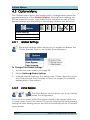
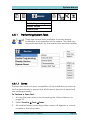
4.3 Options Menu
The Options menu allows the Master user to change and control the
general behavior of the Media Gateway. Among these settings are
Chime, Remote Look-In, and Video Events behavior as well as Zone
Bypass Settings and the ability to temporarily disable user accounts.
Options
Global Settings
Zone Bypass
User Account
4.3.1
Global Settings
The global settings option allows you to enable or disable the
Chime, Remote Look-In, and Video Event Behavior.
To Change The Global Settings:
1.
Access the main menu; see page 22.
2.
Select Options Global Settings.
3.
Mark all relevant options. The options are: Chime, Remote Look-In,
and Video Events. See Glossary of Terms on page 6 for detailed
explanation of the options.
4.3.2
Zone Bypass
The Zone Bypass option allows you to set certain
zones to be bypassed.
This is used for events when the system needs to be armed while one
or more zones cannot be armed. The zones selected will be bypassed
during the next arming session and will automatically return to normal
upon disarm.
Page 23
AlarmView Installation and User Manual
System Menus
To Set Zones for Bypass:
1.
Access the main menu; see page 22.
2.
Select Options Zone Bypass.
3.
Mark all relevant zones.
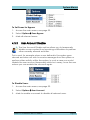
4.3.3
User Account Disable
The User Account Disable option allows you to temporarily
disable a user contact from receiving notifications or perform
other normally allowed activities.
This is used, for example when a user defined in the system goes
abroad and does not wish to receive messages from the system or
perform other activity within the system. In such a case you would
disable the user account temporarily while he is away, once the user
returns you can enable the account again.
To Disable Users:
1.
Access the main menu; see page 22.
2.
Select Options User Account.
3.
Mark to enable or unmark to disable all relevant users.
AlarmView Installation and User Manual
Page 24
System Menus
4.4 Event Log Menu
The Event Log menu allows you to view and
clear the event log.
Event Log
View
Clear
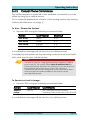
To View the Event Log:
1.
Access the main menu; see page 22.
2.
Select Event Log View.
3.
The display will show the last chronological event in the log and
will include three (3) lines showing the time/date stamp, the event
description, and the event source {Zone # (Zone Name) / User #
(User name) / System / Keyfob # (Name), etc.} For example:
7 / 7 / 2009 , 15:45
BURGLARY ALARM
ZONE 1 (ENTRY DOOR)
CANCEL
4.
Use the Up / Down navigation keys to scroll the event log.
5.
Press the Cancel Soft key to exit the log view menu.
To Clear the Event Log:
1.
Access the main menu, see Accessing the Various Menus, P. 22.
2.
Select Event Log Clear.
3.
A confirmation message will appear, use the soft key to confirm
deletion of the event log.
4.5 Service Menu
The service menu allows you to perform various tests to verify the
installation and operation of the system. In this menu you will also find
the options allowing you to enable programming and USB connection
as well as to view the current software version the system is running,
and when necessary to perform a complete system reset.
Page 25
AlarmView Installation and User Manual
System Menus
SERVICE
Tests
Enable Programming
Display Version
System Reset
4.5.1
Performing System Tests
There are several tests available to ensure proper
installation and operation of the system. The tests can
be performed both by the Master User and the Installer
4.5.1.1 Zones
Perform the zone test upon completion of the installation process as
well as periodically to ensure that all the zones (sensors & detectors)
are working properly.
To Perform a Zone Test:
1.
Access the main menu; see Accessing the Various Menus, on
page 22.
2.
Select Service Tests Zones.
3.
All installed zones (excluding video zones) will appear as a zone
number in the zone table.
AlarmView Installation and User Manual
Page 26
System Menus
1
2
12
5
6
17
23
10
4.
For Video zones there are three scenarios, if the sensor is
available, it will appear checked(), if the zone is empty or
disabled, the box will be empty, if an error occurs, such as no
battery or loss of communication, the zone number will be shown.
5.
Trigger each regular zone, once the zone signal is received, the
zone cell number will be replaced by a check mark ().
6.
Once the test is complete, click OK to exit.
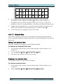
4.5.1.2 External Siren
This menu consists of all of the controllers for servicing the external
siren, including testing, stopping the siren, and relearning the panel to
the siren.
Testing the external siren
The test verifies the behavior of the External Siren.
To Perform An External Siren Test:
1.
Access the main menu; see Accessing the Various Menus, on
page 22.
2.
Select Service Tests External Siren Test.
3.
The External sounder will sound briefly.
Stopping the external siren
This option stops the siren from sounding.
To stop the external siren:
1.
Access the main menu; see Accessing the Various Menus, on
page 22.
2.
Select Service Tests External SirenStop Siren.
Page 27
AlarmView Installation and User Manual
System Menus
Relearning the external siren
In some cases the need arises to resend a signal to the external siren
in order for the siren to reacquaint itself with the panel.
To relearn the external siren:
1.
Access the main menu; see Accessing the Various Menus, on
page 22.
2.
Select Service Tests External Siren Relearn.
3.
The system sends a signal to the external siren.
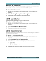
4.5.1.3 Internal Siren Test
The test verifies the behavior of the Internal Siren.
To Perform An Internal Siren Test:
1.
Access the main menu; see Accessing the Various Menus, on
page 22.
2.
Select Service Tests Internal Siren.
3.
The Internal sounder will sound briefly.
4.5.1.4 Communication Test
The test verifies the communication setup by attempting to send and
receive video and data.
To Perform A communication Test:
1.
Access the main menu; see Accessing the Various Menus, on
page 22.
2.
Select Service Tests Communication.
3.
Select the communication test type you wish to perform:
o GPRS Link,
o CMS 1 or 2
o Contact 1, 2, 3, or 4
4.
See the table below for details on each test procedure.
AlarmView Installation and User Manual
Page 28
System Menus
Communication Test Options
Communication
Type
Test Process
Target
LCD
Message
Response
GPRS
Automatically Attempts to open MTeye test Web
Page
MTeye Test
Page
"Wait"
Passed
/Failed
CMS 1...2
Sends a periodic test report to the CMS defined in
CMS contacts (reporting is dependent on the
protocol defined)
"Wait"
Passed
/Failed
User Contacts 1...4
CID SMS / SIA SMSv
CMS Phone
Email Video/CID (MT Video)
CMS Email
GPRS CID / GPRS Video CID
CMS IP & Port
Address
Transmits a “Periodic Test” Text message via MMS, SMS & Email, in succession, and reports after
each one.
SMS Test: Set Mobile Phone + SMS
Event Report (enabled)
Mobile
Phone
"Test SMS"
Passed
/Failed
MMS Test: Set Mobile Phone + MMS Video(enabled)
Mobile
Phone
"Test MMS"
Passed
/Failed
Email Test: Email address + Email Event Report
(enabled)
E-Mail
Address
"Test E-Mail
Text"
Passed
/Failed
Page 29
AlarmView Installation and User Manual
System Menus
4.5.1.5 Self Test
The self test sequence initiates an automatic self test of the system
that checks the processor, screen, etc.
To Perform A Self Test:
1.
Access the main menu; see Accessing the Various Menus, on
page 22.
2.
Select Service Tests System Self Test.
3.
The system will activate a sequence of all the user end displays
and audio’s, LED, LCD, Siren and internal speaker. Once
complete the system will initiate an internal test checking the
CPU, Memory, GSM/GPRS modem, RF, etc.
4.
When the test is complete the system will display a status message
of either Ok or detailed Error Message. Click OK to exit.
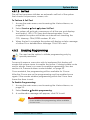
4.5.2
Enabling Programming
The user has the option to initiate programming only by
special permission.
For security reasons, users who wish to implement this feature will
require the system owner to enable the option. If during installer code
was to always, there is no need to enable programming. See also
section 4.6, Passwords Menu under Installer, on page 35.
Once enabled, the programming will be available for 2 hours.
After the 2 hours are up the programming must be enabled once
again. If the master enables programming within the 2 hour time
frame the timer is reset.
To Enable Programming:
1.
Access the main menu; see Accessing the Various Menus, on
page 22.
2.
Select Service Enable programming.
3.
A confirmation message will appear, click OK to exit.
Note:
Once enabled, the programming will be available
for two hours.
AlarmView Installation and User Manual
Page 30
System Menus
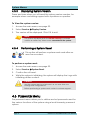
4.5.3
Displaying System Version
There are times when you will need the system version number, for
example when contacting support with a problem or question.
To View the system version:
1.
Access the main menu; see page 22.
2.
Select Service Display Version.
3.
The version will be displayed. Click OK to exit.
Note:
The system will display both the Media Gateway’s software
version as well as any video sensor connected to the system.
4.5.4
Performing a System Reset
This option will perform a system reset used after an
error has occurred.
To perform a system reset:
1.
Access the main menu; see page 22.
2.
Select Service System Reset.
3.
Confirm the soft reset.
4.
While the system is initializing, the system will display the Logo with
initializing written under it.
Caution:
Use the system reset as a last resort, as you may lose your
settings and configurations.
Before performing a system reset contact customer support.
4.6 Passwords Menu
The password menu allows you to define and set passwords used for
the various functions of the system using a level hierarchy password
system.
Page 31
AlarmView Installation and User Manual
System Menus
PASSWORDS
User codes
Master User
Duress Code
24H Limited Code
Installer
4.6.1
User Codes
Define up to four (4) regular passwords, these passwords allow
their users to perform the basic arming options.
When installing an external wireless keypad, and if the system was set
to work with the keypad only the user codes entered can be up to
four (4) digits long and have numeric values between 0 and 9, for
example 0369.
When using the Media Gateway panel for arming and disarming the
system, the user codes can be up to eight (8) digits long and can
contain numeric values of 1 through 4, for example 12341234.
Note:
Grade 2 approval, requires the use of a minimum of
7 digit password when using the media gateway
panel and therefore 1 to 4 numeric values only.
To Set Passwords for Regular Users:
1.
Access the main menu; see page 22.
2.
Select Passwords Regular Users User 1.
Note:
Although the instruction refers to User 1, the same applies to
user 2, 3, and 4.
AlarmView Installation and User Manual
Page 32
System Menus
3.
Select Name. Type a user name.
4.
Select Password. Type the desired password.
Note:
To delete a password entirely use the Delete key to clear all the
digits and leave it blank.
4.6.2
Master User
The master user password is used to access the setup menu as
well as allow the user to perform the basic arming options.
It is highly recommended to change the default Master User password
after completing the installation and setup process.
The Master User code can be up to eight (8) digits long and can
contain numeric values of 1 through 4, for example 11223344.
The Master code cannot be entered via an installed wireless keypad
but needs to be entered directly in the Media Gateway panel.
Note:
Grade 2 approval, requires the use of a minimum of
7 digit password.
To Set a Password for the Master User:
1.
Access the main menu; see page 22.
2.
Select Passwords Master User. Type the desired password.
Note:
The Master User’s password cannot be deleted completely.
4.6.3
Duress Code
The Duress Code is used to send a distress signal to the
designated contact person and /or CMS and act as a Silent
Alarm.
Note:
Check availability of this feature based on the
Firmware version
When installing an external wireless keypad, and if the system was set
to work with the keypad only the Duress code entered, can be up to
four (4) digits long and have numeric values between 0 and 9, for
example 0369.
Page 33
AlarmView Installation and User Manual
System Menus
When using the Media Gateway panel for arming and disarming the
system, the Duress code can be up to eight (8) digits long and can
contain numeric values of 1 through 4, for example 12341234.
Note:
Grade 2 approval, requires the use of a minimum of
7 digit password when using the media gateway
panel and therefore 1 to 4 numeric values only.
To Create a Duress Code:
1.
Access the main menu; see page 22.
2.
Select Passwords Duress Code. Type the desired Code.
Note:
To delete a password entirely use the Delete key to clear all the
digits and leave it blank.
4.6.4
Time (24H) limited Code
The system allows you to create a time limited password, used
to allow temporary workers or house help access without risk.
The allocated password is reset after 24 hours.
Note:
Another Limited Arming option (if enabled in the
system setup) is One Key Arming, which allows, for
example, children, guests, maintenance/cleaning
personnel, etc. to arm the system without the use of
a code. To Disarm the system you will require the use
of an authorized user code.
When installing an external wireless keypad, and if the system was set
to work with the keypad only the time limited code entered, can be
up to four (4) digits long and have numeric values between 0 and 9,
for example 0369.
When using the Media Gateway panel for arming and disarming the
system, the time limited code can be up to eight (8) digits long and
can contain numeric values of 1 through 4, for example 12341234.
Note:
Grade 2 approval, requires the use of a minimum of
7 digit password when using the media gateway
panel and therefore 1 to 4 numeric values only.
To Create a Time Limited Code:
1.
Access the main menu; see page 22.
AlarmView Installation and User Manual
Page 34
System Menus
2.
Select Passwords 24H Limited Code. Type the desired Code.
Note:
To delete a password entirely use the Delete key to clear all the
digits and leave it blank.
4.6.5
Installer
The Installer password is used to access the setup and
programming menus.
It is highly recommended to change the default Installer password
after completing the installation and setup process.
The installer code can be up to eight (8) digits long and can contain
numeric values of 1 through 4, for example 11223344.
The installer code cannot be entered via an installed wireless keypad
but needs to be entered directly in the Media Gateway panel.
Note:
Grade 2 approval, requires the use of a minimum of
7 digit password.
You have the option of setting the installer access to either always in
which case any time the programming menu will be accessible any
time the installer code is entered, or you can limit the access to user
initiated access, in which case the master user needs to allow the
programming menu to be accessed thus preventing changes to the
settings without the user’s knowledge, see also section 4.5.2 Enabling
Programming, on page 30.
To Set a Password for the Installer:
1.
Access the main menu; see Accessing the Various Menus, on
page 22.
2.
Select Passwords Installer Password. Type the desired
password.
Note:
The Installer’s password cannot be deleted
completely.
3.
Define the access mode for the installer, select Passwords
Installer Access Mode. Select either Always or User Initiated.
Page 35
AlarmView Installation and User Manual
System Menus
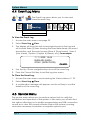
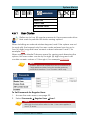
4.7 Set Clock Menu
When starting the system for the first time you need to
set the time and date.
SET CLOCK
Time
Date
To set the Time:
1.
Access the main menu; see page 22.
2.
Select Set Clock.
3.
Select Time to set the time. The time setting window opens.
4.
Use the left soft key to set the time format to either 12H (AM/PM)
or 24H.
5.
Use the Right and Left scroll keys to move the setting indicator
(arrow keys) between the hour and minute boxes.
6.
Use the Up and Down scroll keys to set the time.
7.
Click the confirmation button (OK) to confirm change.
To set the Date:
1.
Access the main menu; see page 22.
2.
Select Set Clock.
3.
Select Date to set the date. The date setting window opens.
4.
Use the left soft key to set the date format to either American
(MM/DD) or European (DD/MM).
5.
Use the Right and Left scroll keys to move the setting indicator
(arrow keys) between the day, month and year boxes.
6.
Use the Up and Down scroll keys to set the date.
7.
Click the confirmation button (OK) to confirm change.
AlarmView Installation and User Manual
Page 36
System Menus
4.8 Stop Communication Menu
The stop communication option allows you to
temporarily stop all communication, all pending
messages are canceled and all communication buffers
are cleared.
This option is normally used by either the installer during the installation
process, during technician testing of the system, or by the user in the
event of a false alarm caused by a procedural error when entering or
exiting the premises.
Stop Communication
To Stop Communication and Clear Buffers:
1.
Access the main menu; see page 22.
2.
Select Stop Communication.
3.
Press OK to confirm, all messages in queue will be erased and will
not be sent.
Page 37
AlarmView Installation and User Manual
Maintenance & Troubleshooting
Appendix A MAINTENANCE & TROUBLESHOOTING
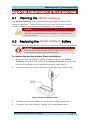
A.1
Cleaning the Media Gateway
The Media Gateway may occasionally get finger oil stains and
accumulate dust. Clean it only with a soft dry cloth or a special
screen cleanser. Avoid the use of abrasives of any kind.
Caution:
Never use solvents such as kerosene, acetone or thinner. These
will harm the external finish and damage the transparency of
the top window.
A.2
Replacing the Media Gateway Battery
After several years the need may arise to replace the backup battery.
Warning:
Remove the transformer from the AC outlet or disconnect the
power before replacing the backup battery.
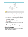
To replace the backup battery (Basic Installation):
1.
Based on the installation method, either remove the Media
Gateway from the wall or open the Media Gateway’s panel and
remove the plastic circuit board enclosure (skip step 2).
2.
Unscrew and remove the battery cover from the back cover.
Figure 10 remove battery cover
3.
Gently pull out the battery wiring from its designated port.
4.
Connect the new battery’s wiring to its designated port.
AlarmView Installation and User Manual
Page 38
Maintenance & Troubleshooting
Figure 11 Connect battery wire
Caution:
It is prudent that you use suitable replacement batteries from
MTEye for best performance and system care.
5.
Depending on your mounting option, either close the battery
cover while fastening the screw and mount the unit back on the
wall. Or close the Media Gateway panel:
o Insert the plastic circuit board enclosure by gently pressing
into place.
o Push down on the two clasps located on both sides of the
plastic circuit board enclosure until you hear an audible click.
Make sure the back tamper button is pressed down firmly by
the backplate’s tamper pin.
o Insert the two closing pins on the front panel of the Media
Gateway into their slots located on the back panel and close
the front panel.
o Replace and tighten the two screws at the bottom of the
Media Gateway using a Philips screwdriver.
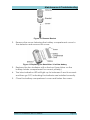
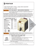
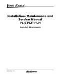
A.3
Replacing the SmartView Battery
When the time comes to replace the batteries in the SmartView /
LiveView, follow these steps.
To Replace the SmartView battery:
1.
Release the screw fastening the bracket to the detector and
separate the bracket from the detector.
Page 39
AlarmView Installation and User Manual
Maintenance & Troubleshooting
Figure 12: Remove Bracket
2.
Remove the screw fastening the battery compartment cover to
the detector and remove the cover.
3.
Replace the two batteries with a fresh set (see sticker on the
battery holder compartment for correct polarity)
4.
The blue indication LED will light up for between 2 and 4 seconds
and then go OFF, indicating the batteries are installed correctly.
5.
Close the battery compartment cover and fasten the screw.
Figure 13 Replacing the SmartView / LiveView battery
AlarmView Installation and User Manual
Page 40
Menu Map
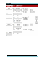
Appendix B MENU MAP
Page 41
AlarmView Installation and User Manual
Useful Tables
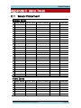
Appendix C USEFUL TABLES
C.1 Sensor Placement
Wireless Zones
#
Zone Name Sensor Type Sensor Location Zone Type Comments
1
2
3
4
5
6
7
8
9
10
11
12
13
14
15
16
17
18
19
20
21
22
23
24
Video Zones
#
Zone Name Sensor Type Sensor Location Zone Type Comments
25
26
27
28
29
30
AlarmView Installation and User Manual
Page 42
Useful Tables
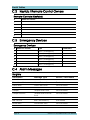
C.2 Keyfob / Remote Control Owners
Remote Controls (Keyfobs)
#
Name Of Owner
1
2
3
4
5
6
C.3 Emergency Devices
Emergency Devices
# Name Of Owner
Type
1
Panic / Emergency
Comments
2
Panic / Emergency
3
Panic / Emergency
4
Panic / Emergency
5
Panic / Emergency
6
Panic / Emergency
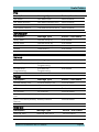
C.4 Alarm Messages
Burglary
Description
Message Type
Device / User Name
Alarm from Zone
Alarm from
Device Name
Zone Alarm Restore
Alarm Restore from
Device Name
Panic Alert
Panic Alert from
Device Name
Panic Alert Restore
Panic Alert Restore from
Device Name
Tamper
Tamper Alert from
Device Name
Tamper Restore
Tamper Alert Restore
from
Device Name
Duress
Duress Alert
Bell Cancel
Bell Canceled by
User Name
Flood Alert
Flood Alert from
Device Name
Flood Alert Restore
Flood Alert Restore from
Device Name
Page 43
AlarmView Installation and User Manual
Useful Tables
Fire
Description
Message Type
Device / User Name
Fire Alarm
Fire Alarm from
Device Name
Fire Alarm Restore
Fire Alarm Restore from
Device Name
Gas Alarm
Gas Alarm from
Device Name
Gas Alarm Restore
Gas Alarm Restore from
Device Name
Description
Message Type
Device / User Name
Away ARM
Armed Away by
User Name
Home ARM
Armed Home by
User Name
Partial ARM
Armed Partial by
User Name
Disarm
Disarmed by
User Name
Disarm after Alarm
Disarmed after Alarm by User Name
Arm/Disarm
Service
Description
Message Type
Device / User Name
Remote Programming
Start Remote
Programming
User Name
End Remote
Programming
End Remote
Programming
User Name
Description
Message Type
Device / User Name
System Battery Low
System Battery Low
Device Name
System Battery Restore
System Battery Restore
Device Name
AC Loss
AC Loss
Device Name
AC Restore
AC Restore
Device Name
Zone / Accessory Battery Battery Low
Low
Device Name
Zone / Accessory Battery Battery Restore
Restore
Device Name
Power
Medical
Description
Message Type
Device / User Name
Medical Alert
Medical Alert from
Device Name
Medical Alert Restore
Medical Alert Restore from Device Name
AlarmView Installation and User Manual
Page 44
Remote Command Tables
Appendix D REMOTE COMMAND TABLES
Here you will find a summary of the remote commands.
Arming Commands
Action
Command Shortcut
Arm Away
AWAY
A, a
Arm Home
HOME
H, h
Arm Partial
PARTIAL
P, p
Disarm
DISARM
D, d
Video Look-In Commands
Action
Command Comments
Request Image
xxI, xxi
(xx – indicates a zone number).
Available zones are zones 25
PGM Commands
Action
Command Comments
Open PGM
xO, xo
x – indicates PGM number 1
Close PGM
xC, xc
x – indicates PGM number 1
Note:
Check availability for additional PGM outputs as an order
option.
Miscellaneous Commands
Action
Command Shortcuts
Stop Bell
BELL
B, b
Check System
Status
STATUS
S, s
Help - Request a
list of commands
?
Page 45
AlarmView Installation and User Manual
Warranty
Appendix E WARRANTY
MTeye Security Ltd. ("the Manufacturer") warrants its products hereinafter referred to
as "the Product" or "Products" to be in conformance with its own plans and
specifications and to be free of defects in materials and workmanships under normal
use and service for a period of twelve (12) months from the date of shipment by the
Manufacturer. The Manufacturer's obligations shall be limited within the warranty
period and its option, to repair or replace the product or any part thereof. The
Manufacturer shall not be responsible for dismantling and/or reinstallation charges. To
exercise the warranty, the product must be returned to the Manufacturer freight
prepared and insured.
The warranty does not apply in the following cases: improper installation, misuse,
failure to follow installation and operating instructions, alteration, abuse, accident or
tampering, and repair by anyone other than the Manufacturer.
The warranty is exclusive and expressly in lieu of all other warranties, obligations or
liabilities, whether written, oral, express or implied, including any warranty of
merchantability or fitness for a particular purpose, or otherwise. In no case shall the
Manufacturer be liable to anyone for any consequential or incidental damages for
breach of this warranty or any other warranties whatsoever, as aforesaid.
This warranty shall not be modified, varied or extended, and the Manufacturer does
not authorize any person to act on its behalf in the modification, variation or extension
of this warranty. This warranty shall apply to the Product only. All products,
accessories or attachments of others used in conjunction with the Product, including
batteries, shall be covered solely by their own warranty, if any. The Manufacturer shall
not be liable for any damage or loss whatsoever, whether directly, indirectly,
incidentally, consequentially or otherwise, caused by the malfunction of the Product
due to products, accessories, or attachments of others, including batteries, used in
conjunction with the Products. The Manufacturer does not represent that its Product
may not be compromised and/or circumvented, or that the Product will prevent any
death, personal and/or bodily injury and/or damage to property resulting from burglary,
robbery, fire or otherwise, or that the Product will in all cases provide adequate
warning or protection. User understands that a properly installed and maintained
alarm may only reduce the risk of events such as burglary, robbery, and fire without
warning, but it is not insurance of a guarantee that such will not occur or there will be
no death, personal damage and/or damage to property as a result.
The Manufacturer shall have no liability for any death, personal and/or bodily injury
and/or damage to property or other loss whether direct, indirect, incidental,
consequential or otherwise, based on a claim that the Product failed to function.
However, if the Manufacturer is held liable, whether directly or indirectly, for any loss
or damage arising under this limited warranty or otherwise, regardless of cause of
origin, the Manufacturer's maximum liability shall not in any case exceed the purchase
price of the Product, which shall be fixed as liquidated damages and not as penalty,
and shall be the complete and exclusive remedy against the Manufacturer.
Warning: The user should follow the installation and operation instructions and among
other things test the product and the whole system at least once a week. For various
reasons, including, but not limited to, changes
in environmental conditions, electric or electronic disruptions and tampering, the
Product may not perform as expected. The user is advised to take all necessary
precautions for his/her safety and the protection of his/her property.
* PATENT PENDING TECHNOLOGY
AlarmView Installation and User Manual
Page 46
Declaration of Conformity
Appendix F DECLARATION OF CONFORMITY
HEREBY,
COMPANY: MTEYE SECURITY LTD
ADDRESS: 11, HAMELACHA ST. AFEK INDUSTRIAL PARK RASH HA’AYIN 48091
COUNTRY: ISRAEL
TELEPHONE NUMBER: +972.3.9008900
FAX NUMBER: +972.3.9008901
MTEYE SECURITY LTD. DECLARES THAT THE ALARMVIEW ™ SYSTEM IS IN COMPLIANCE
WITH THE ESSENTIAL REQUIREMENTS AND OTHER RELEVANT PROVISIONS OF DIRECTIVE
1999/5/EC.
Federal Communications Commission (FCC) Part 15 Statement
This equipment has been tested to FCC requirements and has been found acceptable
for use. The FCC requires the following statement for your information.
This equipment generates and uses radio frequency energy and if not installed and
used properly, that is, in strict accordance with the manufacturer’s instructions, may
cause interference to radio and television reception. It has been type tested and found
to comply with the limits for a Class B computing device in accordance with the
specifications in Part 15 of FCC Rules, which are designed to provide reasonable
protection against such interference in a residential installation. However, there is no
guarantee that interference will not occur in a particular installation. If this equipment
does cause interference to radio or television reception, which can be determined by
turning the equipment off and on, the user is encouraged to try to correct the
interference by one of the following measures:
If using an indoor antenna, have a quality outdoor antenna installed.
Reorient the receiving antenna until interference is reduced or eliminated.
Move the receiver away from the control/communicator.
Plug the control/communicator into a different outlet so that it and the receiver are on
different branch circuits.
If necessary, the user should consult the dealer or an experienced radio/television
technician for additional suggestions.
The user or installer may find the following booklet prepared by the Federal
Communications Commission helpful: “Interference Handbook.” This booklet is
available from the U.S. Government Printing Office, Washington, DC 20402.
The user shall not make any changes or modifications to the equipment unless
authorized by the Installation Instructions or User’s Manual. Unauthorized changes or
modifications could void the user’s authority to operate the equipment.
RoHS compliance - All our products are lead-free
MTeye Security is ISO 9001 and ISO 14001 certified
All data contained herein is subject to change without prior notice.
MTeye Security Ltd.
* Patent Pending Technology
Page 47
AlarmView Installation and User Manual
MTeye Security Ltd.
11 Hamelacha St.
Afek Industrial Park
Rosh Ha’ayin 48091 Israel
Tel: +972.3.900.8900
Fax: +972.3.900.8901
[email protected],
[email protected]
www.mteye.co.il
Distributed and Supported by:
Revision 2.06 October, 2010