1
Avaya
User’s Guide
AVAYA P332MF
STACKABLE SWITCH
SOFTWARE VERSION 3.12
May 2002
Preface
FCC Notice
This equipment has been tested and found to comply with the limits for a Class A
digital device, pursuant to part 15 of the FCC Rules. These limits are designed to
provide reasonable protection against harmful interference when the equipment is
operated in a commercial environment. This equipment generates, uses, and can
radiate radio frequency energy and, if not installed and used in accordance with the
instruction manual, may cause harmful interference to radio communications.
Operation of this equipment in a residential area is likely to cause harmful
interference in which case the user will be required to correct the interference at his
own expense.
Changes or modifications to this equipment not expressly approved by Avaya Inc.
could void the user’s authority to operate the equipment.
Conventions Used in the Documentation
Documentation for this product users the following conventions to convey
instructions and information:
CLI
•
•
•
•
•
•
•
Mandatory keywords you type in are in the computer bold font.
Information displayed on screen is displayed in computer font.
Variables that you supply are in pointed brackets <>.
Optional keywords are in square brackets [].
Alternative but mandatory keywords are grouped in braces {} and separated by
a vertical bar |.
Lists of parameters from which you should choose are enclosed in square
brackets [ ] and separated by a vertical bar |.
If you enter an alphanumeric string of two words or more, enclose the string in
inverted commas.
Avaya P332MF User’s Guide
I
Notes, Cautions and Warnings
Note: Notes contain helpful information or hints or reference to material in other
documentation.
Caution: You should take care. You could do something that may damage
equipment or result in loss of data.
Warning: This means danger. Failure to follow the instructions or warnings may
result in bodily injury. You should ensure that you are qualified for this task and
have read and understood all the instructions
II
Avaya P332MF User’s Guide
Table of Contents
Preface .................................................................................................................. I
FCC Notice........................................................................................................... I
Conventions Used in the Documentation ....................................................... I
CLI .............................................................................................................I
Notes, Cautions and Warnings ............................................................ II
Table of Contents ................................................................................................ i
List of Figures .................................................................................................... ix
List of Tables ...................................................................................................... xi
Chapter 1
Avaya P330 Overview....................................................................................... 1
Avaya P330 Family Features ............................................................................ 1
Avaya P330 Standards Supported................................................................... 2
IEEE .......................................................................................................... 2
IETF ........................................................................................................... 2
Avaya P330 Network Management ................................................................ 2
Avaya P330 Device Manager (Embedded Web) ................................ 2
Avaya P330 Command Line Interface (CLI) ....................................... 2
Avaya Multi-Service Network Manager™ ......................................... 3
Avaya P330 Network Monitoring ................................................................... 3
RMON MIBs - RFC 1757 ........................................................................ 3
SMON MIBs - RFC 2613 ........................................................................ 3
Bridge MIB Groups - RFC 2674 ............................................................ 3
Port Mirroring ......................................................................................... 3
SMON ....................................................................................................... 4
Chapter 2
Applications........................................................................................................
Application 1 ......................................................................................................
Application 2 ......................................................................................................
Application 3 ......................................................................................................
Chapter 3
Avaya P332MF Front and Back Panels ........................................................... 8
Avaya P332MF Front Panel .............................................................................. 8
Avaya P330 Back Panel ................................................................................... 12
BUPS Input Connector ......................................................................... 12
Chapter 4
Installation and Setup...................................................................................... 19
Installing the X330STK Stacking Sub-module in the P330......................... 19
Avaya P332MF User’s Guide
5
5
6
7
i
Table of Contents
Positioning......................................................................................................... 19
Rack Mounting ................................................................................................. 20
Connecting Stacked Switches ......................................................................... 21
To connect stacked switches: ...............................................................21
Installing Expansion Sub-modules ................................................................ 24
Installing the Expansion Sub-module into the Avaya P330 ...........24
Removing an Existing Expansion Sub-module ................................24
Powering On – Avaya P330 Module AC ...................................................... 25
Powering On – Avaya P330 Module DC ...................................................... 25
Configuring the Switch ................................................................................... 26
Avaya P330 Default Settings ...............................................................26
Cabling ....................................................................................................28
Connecting the Console Cable ............................................................29
Configuring the Terminal Serial Port Parameters ............................29
Connecting a Modem to the Console Port ........................................29
Assigning P330’s IP Stack Address ....................................................30
ii
Chapter 5
Avaya CLI – Architecture, Access & Conventions...................................... 31
Establishing a Serial Connection.................................................................... 31
Establishing a Telnet Connection................................................................... 32
Command Line Prompt................................................................................... 33
Avaya P330 Sessions ........................................................................................ 33
Security Levels .................................................................................................. 34
Entering the Supervisor Level .............................................................34
Defining new users ....................................................................34
Exiting the Supervisor Level ....................................................34
Entering the CLI ....................................................................................35
Entering the Technician Level .............................................................35
Conventions Used ............................................................................................ 35
Navigation, Cursor Movement and Shortcuts............................................. 36
Getting Help...................................................................................................... 36
Command Syntax............................................................................................. 36
Command Abbreviations ....................................................................36
Universal Commands ...................................................................................... 37
Top and Up commands ........................................................................37
Retstatus command ..............................................................................37
Tree command .......................................................................................37
Chapter 6
CLI – Layer 2 .................................................................................................... 39
User Level Commands .................................................................................... 39
session .....................................................................................................40
terminal ..................................................................................................40
clear screen .............................................................................................41
ping .........................................................................................................41
Show Commands Summary Table .....................................................42
Avaya P332MF User’s Guide
Table of Contents
show time ............................................................................................... 45
show timezone ...................................................................................... 45
show time parameters .......................................................................... 45
show ip route ......................................................................................... 46
show image version .............................................................................. 46
show download status ......................................................................... 47
show snmp ............................................................................................. 47
show snmp retries ................................................................................ 48
show snmp timeout .............................................................................. 48
show timeout ......................................................................................... 48
show logout ........................................................................................... 48
show interface ....................................................................................... 49
show device-mode ................................................................................ 49
show port ............................................................................................... 50
show port trap ....................................................................................... 51
show port channel ................................................................................ 51
show port classification ....................................................................... 52
show port redundancy ......................................................................... 52
show intermodule port redundancy .................................................. 53
show port mirror .................................................................................. 53
show port vlan-binding-mode ............................................................ 53
show port security ................................................................................ 54
show port blocking ............................................................................... 55
show port self-loop-discovery ............................................................ 57
show internal buffering ....................................................................... 57
show boot bank ..................................................................................... 58
show module ......................................................................................... 58
show port flowcontrol .......................................................................... 60
show cam ............................................................................................... 62
show cascading fault-monitoring ....................................................... 62
show port auto-negotiation-flowcontrol-advertisement ................ 63
show trunk ............................................................................................. 63
show vlan ............................................................................................... 64
show leaky-vlan .................................................................................... 65
show spantree ....................................................................................... 65
show autopartition ............................................................................... 67
show dev log file ................................................................................... 67
show log ................................................................................................. 67
show module-identity .......................................................................... 68
show license ........................................................................................... 68
show system .......................................................................................... 69
show rmon statistics ............................................................................. 70
show rmon history ............................................................................... 71
show rmon alarm .................................................................................. 71
Avaya P332MF User’s Guide
iii
Table of Contents
show rmon event ...................................................................................72
show ppp session ..................................................................................72
show ppp authentication .....................................................................72
show ppp incoming timeout ...............................................................73
show ppp baud-rate .............................................................................73
show ppp configuration .......................................................................73
show tftp download/upload status ...................................................74
show tftp download software status ..................................................74
show web aux-files-url .........................................................................75
show intelligent-multicast ...................................................................75
show intelligent-multicast hardware-support ..................................76
show security mode ..............................................................................76
show secure mac port ...........................................................................77
show arp-tx-interval .............................................................................77
show arp-aging-interval .......................................................................77
show self-loop-discovery .....................................................................78
show allowed managers status ...........................................................78
show allowed managers table .............................................................79
dir ..........................................................................................................79
Privileged Level Commands .......................................................................... 81
no hostname ...........................................................................................82
no rmon history .....................................................................................82
no rmon alarm .......................................................................................82
no rmon event ........................................................................................83
hostname ................................................................................................83
Clear Commands Summary Table .....................................................83
clear timezone ........................................................................................84
clear ip route ..........................................................................................84
clear snmp trap ......................................................................................84
clear vlan ................................................................................................85
clear dynamic vlans ..............................................................................85
clear port static-vlan .............................................................................86
clear cam .................................................................................................86
clear log ..................................................................................................86
clear port mirror ....................................................................................86
clear secure mac ....................................................................................87
Set Commands Summary Table .........................................................88
set logout ................................................................................................91
set timezone ...........................................................................................92
set time protocol ....................................................................................92
set time server ........................................................................................93
set time client .........................................................................................93
set ip route ..............................................................................................93
set snmp community ............................................................................94
iv
Avaya P332MF User’s Guide
Table of Contents
set snmp trap ......................................................................................... 94
set snmp trap auth ................................................................................ 95
set snmp retries ..................................................................................... 95
set snmp timeout .................................................................................. 96
set system location ................................................................................ 96
set system name .................................................................................... 96
set system contact ................................................................................. 96
set device-mode .................................................................................... 97
set interface ............................................................................................ 97
set interface ppp .................................................................................... 98
set port level .......................................................................................... 99
set port negotiation ............................................................................... 99
set port enable ..................................................................................... 100
set port disable .................................................................................... 100
set port speed ...................................................................................... 101
set port duplex .................................................................................... 101
set port name ....................................................................................... 102
set port trap ......................................................................................... 102
set port vlan ......................................................................................... 102
set port vlan-binding-mode .............................................................. 103
set port static-vlan .............................................................................. 103
set port self-loop-discovery Admin_Status .................................... 104
set port channel ................................................................................... 104
set port classification .......................................................................... 105
set port redundancy on/off .............................................................. 106
set port redundancy ........................................................................... 106
set internal buffering .......................................................................... 107
set boot bank ........................................................................................ 107
set intermodule port redundancy .................................................... 108
set intermodule port redundancy off .............................................. 108
set port mirror ..................................................................................... 109
set port spantree .................................................................................. 109
set port spantree priority ................................................................... 110
set port spantree cost .......................................................................... 110
set port security ................................................................................... 111
set cascading ........................................................................................ 111
set inband vlan .................................................................................... 111
set vlan ................................................................................................. 112
set port flowcontrol ............................................................................ 112
set port auto-negotiation-flowcontrol-advertisement ................... 114
set trunk ............................................................................................... 114
set leaky-vlan ....................................................................................... 115
set spantree .......................................................................................... 115
set spantree priority ........................................................................... 115
Avaya P332MF User’s Guide
v
Table of Contents
set autopartition ..................................................................................116
set license ..............................................................................................116
set ppp authentication incoming ......................................................117
set ppp incoming timeout ..................................................................117
set ppp baud-rate ................................................................................117
set web aux-files-url ...........................................................................118
set intelligent-multicast ......................................................................118
set intelligent-multicast client port pruning time ..........................118
set intelligent-multicast router port pruning time .........................119
set intelligent-multicast group-filtering delay time .......................119
set secure mac ......................................................................................119
set security mode ................................................................................120
set arp-aging-interval .........................................................................120
set arp-tx-interval ................................................................................120
set self-loop-discovery Admin_Status .............................................121
set welcome message ..........................................................................121
set allowed managers .........................................................................122
set allowed managers IP ....................................................................122
set psu type ..........................................................................................122
sync time ..............................................................................................123
get time .................................................................................................123
reset .......................................................................................................124
reset stack .............................................................................................124
reset mgp ..............................................................................................125
reset wan ..............................................................................................125
nvram initialize ...................................................................................125
rmon history ........................................................................................126
rmon alarm ...........................................................................................127
rmon event ...........................................................................................128
copy stack-config tftp .........................................................................128
copy module-config tftp .....................................................................129
copy tftp stack-config .........................................................................130
copy tftp module-config .....................................................................130
copy tftp EW_archive .........................................................................131
copy tftp SW_image ............................................................................131
Radius Commands .............................................................................132
set radius authentication secret .........................................................133
set radius authentication server ........................................................133
clear radius authentication server ....................................................133
set radius authentication retry-time .................................................134
set radius authentication retry-number ...........................................134
set radius authentication udp-port ...................................................134
Supervisor Level Commands ....................................................................... 135
username ..............................................................................................135
vi
Avaya P332MF User’s Guide
Table of Contents
no username ........................................................................................ 135
show username ................................................................................... 136
set ppp chap-secret ............................................................................. 136
show radius authentication ............................................................... 136
set radius authentication ................................................................... 137
tech ....................................................................................................... 137
Chapter 7
Installing the Embedded Web Manager.....................................................
System Requirements ....................................................................................
Running the Embedded Web Manager ......................................................
Installing the Java Plug-in.............................................................................
Installing the On-Line Help and Java Plug-In on your Web Site............
Documentation and Online Help ................................................................
Software Download .......................................................................................
Appendix A
Specifications .................................................................................................. 145
Avaya P332MF Switch .................................................................................. 145
Physical ................................................................................................ 145
Power Requirements – AC ................................................................ 145
Power Requirements – DC ................................................................ 145
Laser Data ............................................................................................ 145
Environmental ..................................................................................... 146
Safety .................................................................................................... 146
Avaya P330 DC Input Version .......................................................... 146
Agency Approvals .............................................................................. 146
EMC Emissions ........................................................................ 146
Immunity .................................................................................. 147
Other ......................................................................................... 147
Interfaces .............................................................................................. 147
Standards Compliance ....................................................................... 147
IEEE ........................................................................................... 147
IETF ........................................................................................... 147
Basic MTBF .......................................................................................... 147
Stacking Module ............................................................................................ 148
Expansion Modules ....................................................................................... 148
Gigabit Ethernet Expansion Modules .............................................. 148
Laser Safety .............................................................................. 148
Laser Classification ................................................................. 149
Usage Restriction ..................................................................... 149
Laser Data ................................................................................. 149
Fast Ethernet Fiber Expansion Module ........................................... 150
Ethernet/Fast Ethernet Expansion Module .................................... 150
GBIC Expansion Module ................................................................... 151
Safety Information ................................................................... 151
Usage Restriction ..................................................................... 151
Avaya P332MF User’s Guide
139
139
140
143
144
144
144
vii
Table of Contents
Avaya Approved GBIC Transceivers ...................................152
Specifications ............................................................................152
Agency Approval ....................................................................153
MTBF .........................................................................................153
X330GT2 Gigabit Ethernet Expansion Module ...............................153
Installing the Expansion Module in the Avaya P330 .........153
Removing an Existing Expansion Module ...........................154
Cabling ......................................................................................154
ATM Expansion Modules ..................................................................155
Safety Information ...................................................................155
Backup Power Supply (BUPS)...................................................................... 156
Physical .................................................................................................156
Power Requirements ..........................................................................156
Environmental .....................................................................................157
Safety .....................................................................................................157
EMC Emissions ...................................................................................157
Emissions ..................................................................................157
Immunity ..................................................................................157
BUPS MTBF .........................................................................................157
MTBF in Various Configurations................................................................. 158
Index of CLI Commands ............................................................................... 159
How to Contact Us ..................................................................................................................... 163
In the United States .............................................................................163
In the EMEA (Europe, Middle East and Africa) Region ...............163
In the AP (Asia Pacific) Region .........................................................165
In the CALA (Caribbean and Latin America) Region ...................165
viii
Avaya P332MF User’s Guide
List of Figures
Figure 2.1
Backbone
Figure 2.2
Figure 2.3
Figure 3.1
Figure 3.2
Figure 3.3
Figure 3.4
Figure 4.1
Figure 4.2
Figure 4.3
Figure 7.1
Figure 7.2
Avaya P332MF User’s Guide
Avaya P333T and Avaya P334T stacks with an Avaya P882
......................................................................................................... 5
Avaya P330 stacks with an Avaya 330 backbone .................... 6
Avaya P332MF with an Avaya P882 backbone ....................... 7
Avaya P332MF Front Panel ........................................................ 8
Avaya P332MF LEDs ................................................................... 9
Avaya P330 AC and DC Back Panels ...................................... 12
BUPS Input Connector Sticker ................................................. 12
Avaya P330 Rack Mounting .................................................... 20
Incorrect Stack Connection ....................................................... 22
Avaya P330 Stack Connections ................................................ 23
The Welcome Page ................................................................... 141
Web-based Manager ................................................................ 142
ix
List of Figures
x
Avaya P332MF User’s Guide
List of Tables
Table 3.1
Table 3.2
Table 4.1
Table 4.2
Table 4.3
Table 5.1
Table 7.1
Table A.1
Table A.2
Table A.3
Table A.4
Table A.5
Table B.6
Table B.7
Avaya P332MF User’s Guide
Avaya P332MF LED Descriptions ............................................. 9
Avaya P330 <- -> Select buttons............................................... 10
Default Switch Settings ............................................................. 26
Default Port Settings .................................................................. 27
Gigabit Ethernet Cabling........................................................... 28
Navigation, Cursor Movement and Shortcuts....................... 36
Embedded Web Manager/Browser Compatability............ 140
Stacking Module....................................................................... 148
Gigabit Ethernet Expansion Modules ................................... 148
Fiber Fast Ethernet Expansion Module................................. 150
Ethernet/Fast Ethernet Expansion Module ......................... 150
..................................................................................................... 158
..................................................................................................... 158
MTBF for the Avaya P332MF in Various Configurations .. 158
xi
List of Tables
xii
Avaya P332MF User’s Guide
Chapter 1
Avaya P330 Overview
The Avaya P330 family of stackable Ethernet workgroup switches includes a range
of modules with 10/100/1000 Mbps ports and a Layer 3 capability/ATM Expansion
Module. The Avaya P332MF switch has 12x100BaseFX MT-RJ ports and an
Expansion Module slot. The optional expansion modules provide additional
Ethernet, Fast Ethernet, and Gigabit Ethernet connectivity.
An Avaya P330 stack can contain up to 10 switches and up to 3 backup power
supply units. The stacked switches are connected using the Avaya X330STK
stacking Modules which plug into a slot in the back of the Avaya P330. They are
connected using the X330SC or X330LC cable (if the stack is split between two
racks). The Avaya X330RC cable connects the top and bottom switches in the stack
and provides redundancy and hot-swappability in the same way that modules can
be swapped in a modular switching chassis.
The Avaya P330 is fully compliant with IEEE standards for VLAN Tagging, Gigabit
Ethernet, Spanning Tree and Flow Control. This full standards-compliance,
combined with auto-negotiation for 10/100/1000 Mbps and half/full duplex
facilitates the expansion of your network to match your company's growing needs.
Avaya P330 Family Features
•
•
•
•
•
•
•
•
You can connect up to 10 Avaya P330 switches in a stack. Moreover, this stack
can be either in one rack or split over several racks using the X330LC Long
Cable, according to your requirements.
Avaya X330STK - this stacking Module is used to connect Avaya P330 switches
in a stack, via the Octaplane.
Avaya P330 BUPS - this back-up power supply module supports up to four
Avaya P330 switches.
One RJ-45/RS232 front panel console connector for both terminal and modem
sessions.
Two fan units in every switch, with operation sensors.
One virtual IP address for managing the whole stack, the P330 stack is managed
as a single entity.
Hot-swapping of one switch at a time - by activation of the redundant cable:
— Does not disrupt the operation of other Avaya P330 switches.
— Does not change stack configuration.
— Does not require network downtime.
Connection through Telnet from the front panel ports of any switch, with:
— multiple levels of password protection
— login and inactivity timeouts
Avaya P332MF User’s Guide
1
Chapter 1
Avaya P330 Overview
Avaya P330 Standards Supported
The Avaya P330 complies with the following standards.
IEEE
•
•
•
•
•
802.3x Flow Control on all ports
802.1Q VLAN Tagging support on all ports and 802.1p compatible
802.1D Bridges and STA
803.2z Gigabit Ethernet ports
803.2u Ethernet/Fast Ethernet ports
•
•
•
•
•
MIB-II - RFC 1213
Bridge MIB for Spanning Tree - RFC 1492
RMON - RFC 1757
SMON - RFC 2613
Bridge MIB Groups - RFC 2674 dot1dbase and dot1dStp fully implemented.
Support for relevant MIB objects: dot1q (dot1qBase, dot1qVlanCurrent)
IETF
Avaya P330 Network Management
Comprehensive network management is a key component of today’s networks.
Therefore we have provided multiple ways of managing the Avaya P330 to suit
your needs.
Avaya P330 Device Manager (Embedded Web)
The built-in Avaya P330 Device Manager (Embedded Web Manager) allows you to
manage an Avaya P330 stack using a Web browser without purchasing additional
software. This application works with the Microsoft® Internet Explorer and
Netscape® Navigator web browsers and Sun Microsystems Java™ Plug-in.
Avaya P330 Command Line Interface (CLI)
The Avaya P330 CLI provides a terminal type configuration tool for local or remote
configuration of Avaya P330 features and functions.
2
Avaya P332MF User’s Guide
Chapter 1
Avaya P330 Overview
Avaya Multi-Service Network Manager™
When you need extra control and monitoring or wish to manage other Cajun
Campus equipment, then the Avaya Multi-Service Network Manager network
management suite is the answer. This suite provides the ease-of-use and features
necessary for optimal network utilization.
• Avaya Multi-Service Network Manager is available for Windows® NT®/2000
and Solaris 8.
• Avaya Multi-Service Network Manager can operate in Stand-Alone mode with
Windows® NT®/2000.
• Avaya Multi-Service Network Manager operates under HP OpenView for
Windows® NT®/2000 and Solaris 8.
Avaya P330 Network Monitoring
RMON MIBs - RFC 1757
• RMON support for groups 1,2,3 and 9
— Statistics
— History
— Alarms
— Events
SMON MIBs - RFC 2613
• SMON support for groups
— Data Source Capabilities
— Port Copy
— VLAN and Priority Statistics
Bridge MIB Groups - RFC 2674
• dot1dbase and dot1dStp fully implemented.
• Support for relevant MIB objects: dot1q (dot1qBase, dot1qVlanCurrent)
Port Mirroring
The Avaya P330 provides port mirroring for additional network monitoring
functionality. You can filter the traffic and mirror either incoming traffic to the
source port or both incoming and outgoing traffic. This allows you to monitor the
network traffic you need.
Ports which are members in a Link Aggregation Group (LAG) cannot also be used as
Port Mirroring Destination or Source ports.
Avaya P332MF User’s Guide
3
Chapter 1
Avaya P330 Overview
SMON
The Avaya P330 supports Avaya’s ground-breaking SMON Switched Network
Monitoring, which the IETF has now adopted as a standard (RFC2613). SMON
provides an unprecedented top-down monitoring of switched network traffic at the
following levels:
• Enterprise Monitoring
• Device Monitoring
• VLAN Monitoring
• Port-level Monitoring
This top-down approach gives you rapid troubleshooting and performance
trending to keep the network running optimally.
Note: Avaya Multi-Service Network Manager is required to run SMON monitoring.
Note: You need to purchase one SMON License per Avaya P330 Stack.
4
Avaya P332MF User’s Guide
Chapter 2
Applications
The following sections describe typical applications for the Avaya P330 in a network
with other Cajun Campus products.
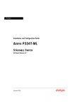
Application 1
This application shows Avaya P882 as the network backbone with Avaya P333T and
Avaya P334T stacks as closet devices with LAG and redundant links.
Figure 2.1
Avaya P333T and Avaya P334T stacks with an Avaya P882 Backbone
10/100 Mbps
Ethernet
Avaya P333T
Avaya P333T
10/100 Mbps Ethernet
Avaya P334T
LAG
Redundancy
Avaya P334T
Avaya P334T
Avaya P334T
Avaya P334T
Avaya P334T
Avaya P333T
Avaya P334T
10/100 Mbps Ethernet
Gigabit Ethernet
with LAG
4x100 Mbps
LAG
Avaya P880
Gigabit Ethernet
with LAG
Avaya P882
Avaya P332MF User’s Guide
4x100 Mbps
LAG
5
Chapter 2
Applications
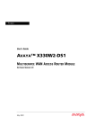
Application 2
This application shows an Avaya P330 stack forming the backbone of a Small/
Medium-sized Enterprise (SME) network with Avaya P330 stacks as closet devices
with LAN and redundant links.
Figure 2.2
Avaya P330 stacks with an Avaya 330 backbone
Avaya P330
Avaya P330
LAG
Redundancy
10/100 Mbps Ethernet
10/100 Mbps Ethernet
Gigabit Ethernet
with LAG
10/100 Mbps Ethernet
4x100 Mbps
LAG
Gigabit Ethernet
with LAG
4x100 Mbps
LAG
6
Avaya P332MF User’s Guide
Chapter 2
Applications
Application 3
This application shows Avaya P880 as the network backbone with Avaya P332MF
deployed as a distribution switch. An Avaya P333R multilayer switch provides local
IP routing. The Avaya P333T stacks act as closet devices with LAG and redundant
links.
Figure 2.3
Avaya P332MF with an Avaya P882 backbone
10/100 Mbps Ethernet
LAG
Redundancy
10/100 Mbps Ethernet
100 Mbps
Fiber Optic
Ethernet
with LAG
10/100 Mbps
Ethernet
100 Mbps
Fiber Optic
Ethernet
with LAG
10/100 Mbps Ethernet
LAG
Redundancy
LAG
Redundancy
Avaya P332MF
Avaya P332MF
Avaya P333R
Gigabit Ethernet
with LAG
10/100 Mbps
Ethernet
Server Farm
Avaya P880
Gigabit Ethernet
with LAG
Avaya P882
Avaya P332MF User’s Guide
4x100 Mbps
LAG
7
Chapter 3
Avaya P332MF Front and Back Panels
Avaya P332MF Front Panel
The Avaya P332MF front panel contains LEDs, controls, connectors and an
expansion Module slot, as well as a console connector. The status LEDs and control
buttons provide at-a-glance information.
The front panel LEDs consist of Port LEDs and Function LEDs. The Port LEDs
display information for each port according to the illuminated function LED. The
function is selected by pressing the left or right button until the desired parameter
LED is illuminated.
For example, if the COL LED is illuminated, then all Port LEDs show the collision
status of their respective port. If you wish to select the LAG function, then press the
right button until the LAG Function LED is lit; if you then wish to select Rx then
press the left button several times until the Rx function LED lights.
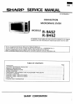
Figure 3.1 shows the Avaya P332MF front panel. Figure 3.2 shows a detailed view
of the LEDs (described in Table 3.1), pushbuttons, the Expansion Module slot, and
the RJ-45 console connector at the bottom right.
Figure 3.1
Avaya P332MF Front Panel
Avaya P332MF User’s Guide
8
Chapter 3
Figure 3.2
Avaya P332MF Front and Back Panels
Avaya P332MF LEDs
Port LEDs
51
52
53
54
55
56
57
58
59
60
61
62
63
64
65
66
1
2
Tx
Rx
3
4
5
6
7
8
9
10
11
12
EXPANSION
SLOT
LNK
COL
FDX
FC
Hspd LAG
SYS OPR PWR
FIV
Left/Right
and Reset (both)
Switches
FIV Switch
Function LEDs
Note: All LEDs are lit during a reset.
Table 3.1
Avaya P332MF LED Descriptions
LED Name
Description
LED Status
OFF – power is off
PWR
Power status
ON – power is on
Blink – using BUPS only
OPR
CPU operation
OFF – Module is booting
ON – Normal operation
OFF – Module is a slave in a stack
SYS
System Status
ON – Module is the Master of the stack and
the Octaplane and Redundant cable are
connected correctly.
This LED will also light in Standalone mode.
Blink – Box is the stack Master and the stack
is in redundant mode.
The following Function LEDs apply to ports 1 to 66
OFF – Port disabled
LNK
Port status
ON – Port enabled and link OK
Blink – Port enabled and the link is down
Avaya P332MF User’s Guide
9
Chapter 3
Avaya P332MF Front and Back Panels
Table 3.1
Avaya P332MF LED Descriptions
LED Name
Description
COL
Collision
LED Status
OFF – No collision or FDX port
ON – Collision occurred on line
OFF – No transmit activity
Tx
Transmit to line
ON – Data transmitted on line from the
module
OFF – No receive activity
Rx
Receive from line
FDX
Half/Full Duplex
ON – Data received from the line into the
module
OFF – Half duplex mode
ON – Full duplex mode
OFF – No Flow Control
FC
Flow Control
Hspd
High Speed
ON – Symmetric/Asymmetric Flow Control
mode is enabled and port is in full duplex
mode.
OFF:
ON:
Link Aggregation
Group (Trunking)
LAG
Table 3.2
10
10/100
10
100
1000
N/A
1000
OFF – No LAG defined for this port
ON – Port belongs to a LAG
Avaya P330 <- -> Select buttons
Description
Function
Left/Right
Individual – select LED function (see table above).
Reset module
Press both right and left buttons together for approximately two
seconds. All LEDs on module light up until buttons are
released.
Reset stack
Press both right and left buttons together for 4 seconds. All
LEDs on stack light up until buttons are released.
FIV
Force Initial Version – boot from backup initial version of the
Avaya P330 software, from Bank A (see Note below).
Avaya P332MF User’s Guide
Chapter 3
Avaya P332MF Front and Back Panels
Note: To perform “Force Initial Version” reset the module and at the same time
press the FIV reset button (use an opened paper clip or other pointed object).
Release the reset buttons first and 1 or 2 seconds later, release the FIV button.
Note: The Port LEDs of the P332MF are numbered from 1-12. Expansion Module
ports are numbered from 51. Port LED numbers 49-50 are reserved.
Avaya P332MF User’s Guide
11
Chapter 3
Avaya P332MF Front and Back Panels
Avaya P330 Back Panel
The Avaya P330 back panel contains a stacking sub-module slot, power supply and
BUPS connector. Figure 3.3 shows the back panel of the AC switch (top) and the DC
switch (bottom) with a stacking sub-module installed.
Figure 3.3
Avaya P330 AC and DC Back Panels
Note: Further illustrations of the Avaya P330 Back Panel will be that of the AC
model, the topmost panel in Figure 3.3.
Figure 3.3 shows the back panel of the AC switch (top) and the DC switch (bottom)
with a stacking sub-module installed.
BUPS Input Connector
The BUPS input connector (see Figure 3.4) is a 5 VDC connector for use with the
Avaya P330 BUPS unit only. A BUPS Input sticker appears directly to the right the
BUPS input connector.
Figure 3.4
BUPS Input Connector Sticker
BUPS Input
12
Avaya P332MF User’s Guide
Chapter 3
Avaya P332MF User’s Guide
Avaya P332MF Front and Back Panels
13
Chapter 3
14
Avaya P332MF Front and Back Panels
Avaya P332MF User’s Guide
Chapter 3
Avaya P332MF User’s Guide
Avaya P332MF Front and Back Panels
15
Chapter 3
16
Avaya P332MF Front and Back Panels
Avaya P332MF User’s Guide
Chapter 3
Avaya P332MF User’s Guide
Avaya P332MF Front and Back Panels
17
Chapter 3
18
Avaya P332MF Front and Back Panels
Avaya P332MF User’s Guide
Chapter 4
Installation and Setup
The Avaya P332MF is ready to work after you carry out the installation instructions
given below. All the Avaya P332MF ports provide complete connectivity and no
configuration is required to make the system work.
Installing the X330STK Stacking Sub-module in the P330
Caution: The stacking sub-modules contain components sensitive to electrostatic
discharge. Do not touch the circuit board unless instructed to do so.
To install the stacking sub-module in the Avaya P330:
1 Remove the blanking plate from the back of the Avaya P330 switch.
2 Insert the stacking sub-module gently into the slot, ensuring that the metal base
plate is aligned with the guide rails.
The metal plate of the X330STK (and not the PCB) fits onto the guide rails.
3 Press the sub-module in firmly until it is completely inserted into the
Avaya P330.
4 Gently tighten the two screws on the side panel of the stacking sub-module by
turning them.
Note: The Avaya P330 switch must not be operated with the back-slot open; the
stacking sub-module should be covered with the supplied blanking plate if necessary.
Positioning
Avaya P330 can be mounted alone or in a stack in a standard 19-inch equipment
rack in a wiring closet or equipment room. Up to 10 units can be stacked in this way.
When deciding where to position the unit, ensure that:
• It is accessible and cables can be connected easily and according to the
configuration rule.
• Cabling is away from sources of electrical noise such as radio transmitters,
broadcast amplifiers, power lines and fluorescent lighting fixtures.
• Water or moisture cannot enter the case of the unit.
• There is a free flow of air around the unit and that the vents in the back and
sides of the case are not blocked.
Avaya P332MF User’s Guide
19
Chapter 4
Installation and Setup
Note: Use Octaplane cables to interconnect with other switches.
Rack Mounting
The Avaya P330 case fits in most standard 19-inch racks. Avaya P330 is 2U (88mm,
3.5”) high.
Place the Avaya P330 in the rack as follows:
1 Snap open the hinged ends of the front panel to reveal the fixing holes.
2 Insert the unit into the rack. Ensure that the four Avaya P330 screw holes are
aligned with the rack hole positions as shown in Figure 4.1.
Figure 4.1
3
4
5
20
Avaya P330 Rack Mounting
Secure the unit in the rack using the screws. Use two screws on each side. Do
not overtighten the screws.
Snap closed the hinged ends of the front panel.
Ensure that ventilation holes are not obstructed.
Avaya P332MF User’s Guide
Chapter 4
Installation and Setup
Connecting Stacked Switches
Note: The two ends of the Octaplane cable terminate with different connectors. Each
connector can only be connected to its matching port.
The following cables are used to connect stacked switches:
• Short Octaplane cable (X330SC) – ivory-colored, used to connect adjacent
switches (Catalog No. CB0223) or switches separated by a BUPS unit.
• Long/Extra Long Octaplane cable (X330LC/X330L-LC) – ivory-colored, used to
connect switches from two different physical stacks, or switches separated by a
BUPS unit (Catalog No. CB0225/CB0270).
• Redundant/Long Redundant Octaplane cable (X330RC/X330L-RC) – black,
used to connect the top and bottom switches of a stack (Catalog No. CB0222/
CB0269).
These are the same cables that are used with all P330 family modules.
To connect stacked switches:
Note: When adding a module to an existing stack, first connect the stacking cables
and then power up the module.
1
2
3
4
5
Plug the light grey connector of the Short Octaplane cable into the port marked
“to upper unit” of the bottom Avaya P330 switch.
Plug dark grey connector of same Short Octaplane cable to the port marked “to
lower unit” in the unit above. The connections are illustrated in Figure 4.3.
Repeat Steps 1 and 2 until you reach the top switch in the stack.
If you wish to implement stack redundancy, use the Redundant Cable to
connect the port marked “to lower unit” on the bottom switch to the port
marked “to upper unit” on the top switch of the stack.
Power up the added modules.
Caution: Do not cross-connect two Avaya P330 switches with two Octaplane (lightcolored) cables. If you wish to cross-connect for redundancy, use one light-colored
Octaplane cable and one black redundancy cable. Figure 4.2 shows an incorrect
connection.
Avaya P332MF User’s Guide
21
Chapter 4
Installation and Setup
Note: You can build a stack of up to 10 Avaya P330 switches. If you do not wish to
stack all the switches in a single rack, use long Octaplane cables to connect two
physical stacks as shown in Figure 4.3.
Figure 4.2
Incorrect Stack Connection
BUPS
Connector
Cable to
Lower Unit
Cable to
Upper Unit
Cable to
Lower Unit
Cable to
Upper Unit
Power Supply
Connector
BUPS
Connector
Power Supply
Connector
22
Avaya P332MF User’s Guide
Chapter 4
Figure 4.3
Installation and Setup
Avaya P330 Stack Connections
BUPS
Connector
BUPS
Connector
Cable to
Lower Unit
Cable to
Upper Unit
5
Power Supply
Connector
X330SC
BUPS
Connector
Cable to
Lower Unit
Cable to
Upper Unit
Cable to
Upper Unit
10
Cable to
Lower Unit
Cable to
Upper Unit
9
Cable to
Lower Unit
Cable to
Upper Unit
Cable to
Lower Unit
Cable to
Upper Unit
Cable to
Lower Unit
Cable to
Upper Unit
BUPS
Connector
4
Power Supply
Connector
Power Supply
Connector
BUPS
Connector
BUPS
Connector
Cable to
Lower Unit
Cable to
Upper Unit
3
Power Supply
Connector
8
Power Supply
Connector
BUPS
Connector
BUPS
Connector
Cable to
Lower Unit
Cable to
Upper Unit
2
Power Supply
Connector
Power Supply
Connector
BUPS
Connector
BUPS
Connector
X330RC
Power Supply
Connector
Cable to
Lower Unit
Power Supply
Connector
Cable to
Lower Unit
Cable to
Upper Unit
1
7
6
Power Supply
Connector
X330LC
Avaya P332MF User’s Guide
23
Chapter 4
Installation and Setup
Installing Expansion Sub-modules
Caution: The expansion sub-modules contain components sensitive to electrostatic
discharge. Do not touch the circuit board unless instructed to do so.
Installing the Expansion Sub-module into the Avaya P330
1 Remove the blanking plate or other sub-module (if installed).
2 Insert the sub-module gently into the slot, ensuring that the Printed Circuit
Board (PCB) is aligned with the guide rails.
The PCB not the metal base plate fits into the guide rail.
3 Firmly press the sub-module until it is completely inserted into the Avaya P330.
4 Gently tighten the two screws on the front panel of the expansion sub-module
by turning them.
Removing an Existing Expansion Sub-module
1 Loosen the screws by turning the knobs.
2 Take hold of the two knobs (one near each side of the front panel) and pull
gently but firmly towards yourself.
3 Insert another expansion sub-module or the blanking plate.
Note: If an expansion sub-module is removed from the stack with the power supply
on, all configuration definitions on expansion sub-modules are lost. To remove an
expansion sub-module and save configuration definitions:
1 Turn off the power supply.
2 Remove an expansion sub-module.
3 Insert another expansion sub-module.
4 Turn on the power supply.
Note: The Avaya P330 switch must not be operated with the expansion slot open;
the expansion sub-module slot should be covered with the supplied blanking plate
if necessary.
24
Avaya P332MF User’s Guide
Chapter 4
Installation and Setup
Powering On – Avaya P330 Module AC
For the AC input version of the Avaya P330, insert the AC power cord into the
power inlet in the back of the unit. The unit powers up even if no direct AC power is
applied to it.
1 If you are using a BUPS, insert a power cord from the BUPS into the BUPS
connector in the back of the unit. The unit powers up.
2 After power up or reset, the Avaya P330 performs a self test procedure.
Powering On – Avaya P330 Module DC
For the DC input version of the Avaya P330, connect the power cable to the switch
at the input terminal block.
1 The terminals are marked “+”, “-“ and with the IEC 5019a Ground symbol.
2 The size of the three screws in the terminal block is M3.5.
3 The pitch between each screw is 9.5mm.
Warning: Before performing any of the following procedures, ensure that DC power
is OFF.
Caution: This product is intended for installation in restricted access areas and is
approved for use with 18 AWG copper conductors only. The installation must
comply with all applicable codes.
4
Connect the power cable to the DC power supply.
Warning: The proper wiring sequence is ground to ground, positive to positive and
negative to negative. Always connect the ground wire first and disconnect it last.
Avaya P332MF User’s Guide
25
Chapter 4
Installation and Setup
Configuring the Switch
The Avaya P330 may be configured using the text-based Command Line Interface
(CLI), the built-in Avaya P330 Device Manager (Embedded Web) or Avaya MultiService Network Manager™.
For instructions on the text-based utility, see the CLI chapter.
For instructions on installation of the graphical user interfaces, see the Avaya P330
Device Manager Appendix. For instructions on the use of the graphical user
interfaces, refer to the Device Manager User’s Guide on the Documentation and
Utilities CD.
Avaya P330 Default Settings
The default settings for the Avaya P330 switch and its ports are determined by the
Avaya P330 software. These default settings are subject to change in newer versions
of the Avaya P330 software. See the Release Notes for the most up-to-date settings.
Table 4.1
26
Default Switch Settings
Function
Default Setting
IP address
149.49.32.134
Default gateway
0.0.0.0
VLANs
VLAN 1
Spanning tree
Enabled
Bridge priority for Spanning Tree
32768
Time server IP address
0.0.0.0
Timezone offset
0 hours
Read-only SNMP community string
Public
Read-write SNMP community string
Public
Trap SNMP community string
Public
SNMP retries number
3
SNMP timeout
2000 Seconds
SNMP authentication trap
Disabled
CLI timeout
15 Minutes
User Name/Password
root/root
Avaya P332MF User’s Guide
Chapter 4
Table 4.2
Installation and Setup
Default Port Settings
Function
Default Setting
10/100Base-TX ports
100Base-F ports
1000 Base-X ports
Duplex mode
Full duplex
Full duplex
Full duplex only
Port Speed
100M
100M
1000M
Flow control
Off
Off
Off
Flow control
advertisement
Off
N/A
Off (No pause)
Backpressure
On (only in Half duplex)
Not Applicable
Not Applicable
Autopartitioning
Disabled (only in Half
duplex)
N/A
N/A
Auto-negotiation
Enable
Not Applicable
Enable1
Administration status
Enable
Enable
Enable
Port VLAN
1
1
1
Tagging mode
Clear
Clear
Clear
Port priority
0
0
0
Spanning Tree cost
20
20
4
Spanning Tree port
priority
128
128
128
1 Ensure that the other side is also set to Autonegotiation Enabled
Note: Functions operate in their default settings unless configured otherwise.
Avaya P332MF User’s Guide
27
Chapter 4
Installation and Setup
Cabling
Avaya P330 modules include the following types of ports (according to the speed
and standard they support): 10Base-T, 100Base-TX, 100Base-FX, 1000Base-SX and
1000Base-LX.
Note: To interconnect Avaya P330 switches with twisted pairs, crossed cables are
required.
•
•
•
•
The maximum UTP cable length connected to a 10/100 Mbps port operating as
10Base-T, is 100 m (328 ft.).
A UTP Category 5 cable must be connected to any 100Base-TX port, via an RJ45
connector. The maximum UTP cable length connected to a 10/100 Mbps port
operating as 100Base-TX, is 100 m (328 ft.).
A fiberoptic cable must be connected to any 100Base-FX port, via a pair of SC
connectors. The maximum fiber cable length connected to a 100Base-FX port is
412 m (1,352 ft) when operating in half duplex, and 2 km (6,562 ft) when
operating in full duplex.
The maximum length of fiber optic cable connected to a 12 fiber MT-RJ port is 2
km (6,562 ft).
Appropriate cables are available from your local supplier.
Table 4.3
28
Gigabit Ethernet Cabling
Gigabit
Interface
Fiber
Type
Diameter
(µm)
Modal
Bandwidth
(MhzKm)
Maximum
Distance
(m)
Minimum
Wavelength
Distance
(nm)
(m)
1000BASE-SX
MM
62.5
160
220
2
850
1000BASE-SX
MM
62.5
200
275
2
850
1000BASE-SX
MM
50
400
500
2
850
1000BASE-SX
MM
50
500
550
2
850
1000BASE-LX
MM
62.5
500
550
2
1310
1000BASE-LX
MM
50
400
550
2
1310
1000BASE-LX
SM
9
NA
10,000
2
1310
Avaya P332MF User’s Guide
Chapter 4
Installation and Setup
Connecting the Console Cable
The Avaya P330 has one serial port on the front panel of the switch for connecting a
terminal, a terminal emulator, or a modem.
The serial port on the front panel is labelled “Console” and has a RJ-45 connector.
Connect the P330 to a terminal or a terminal emulator using the supplied console
cable and the RJ-45 to DB-9 adaptor. To connect a modem, use the supplied cable
and an RJ-45 to DB-25 adaptor.
Note: The cable and two adaptors can be found in the accessory set, and they are
clearly marked.
Configuring the Terminal Serial Port Parameters
The serial port settings for using a terminal or terminal emulator are as follows:
• Baud Rate - 9600 bps
• Data Bits - 8 bits
• Parity - None
• Stop Bit - 1
• Flow Control - None
• Terminal Emulation - VT-100
Connecting a Modem to the Console Port
A PPP connection with a modem can be established only after the
Avaya P330 is configured with an IP address and net-mask, and the PPP parameters
used in the Avaya P330 are compatible with the modem’s PPP parameters.
1 Connect a terminal to the console port of the Avaya P330 switch as described in
Connecting the Console Cable on page 29.
2 When you are prompted for a Login Name, enter the default name root.
3 When you are prompted for a password, enter the password root. You are
now in Supervisor Level.
4 At the prompt, type:
set interface ppp <ip_addr><net-mask>
with an IP address and netmask to be used by the Avaya P330 to connect via its
PPP interface.
Note: The PPP interface configured with the set interface ppp command
must be on a different subnet from the stack inband interface.
Avaya P332MF User’s Guide
29
Chapter 4
Installation and Setup
5
6
Set the baud rate, ppp authentication, and ppp time out required to match your
modem. These commands are described in the “Command Line Interface”
chapter.
At the prompt, type:
set interface ppp enable
The CLI responds with the following:
Entering the Modem mode within 60 seconds...
7
8
9
Please check that the proprietary modem cable is plugged
into the console port
Use the DB-25 to RJ-45 connector to plug the console cable to the modem’s DB25 connector. Plug the other end of the cable RJ-45 connector to the
Avaya P330 console’s RJ-45 port.
The Avaya P330 enters modem mode.
You can now dial into the switch from a remote station, and open a Telnet
session to the PPP interface IP address.
Assigning P330’s IP Stack Address
Note: All P330 switches are shipped with the same default IP address. You must
change the IP address of the master P330 switch in a stack in order to guarantee that
the stack has its own unique IP address in the network.
Use the CLI to assign the P330 stack an IP address and net mask. The network
management station can establish communications with the stack once this address
had been assigned and the stack has been inserted into the network.
To assign a P330 IP stack address:
1 Establish a serial connection by connecting a terminal to the Master P330 switch
of the stack.
2 When prompted for a Login Name, enter the default name root
3 When you are prompted for a password, enter the password root. You are
now in Supervisor Level.
4 At the prompt, type:
set interface inband <vlan> <ip_address> <netmask>
Replace <vlan>, <ip_address> and <netmask> with the VLAN,
IP address and net mask of the stack.
5 Press Enter to save the IP address and net mask.
6 At the prompt, type reset and press Enter to reset the stack. After the Reset,
log in again as described above.
7 At the prompt, type set ip route <dest> <gateway> and replace <dest>
and <gateway> with the destination and gateway IP addresses.
8 Press Enter to save the destination and gateway IP addresses.
30
Avaya P332MF User’s Guide
Chapter 5
Avaya CLI – Architecture, Access & Conventions
This chapter describes the Avaya P330 CLI architecture and conventions, and
provides instructions for accessing the Avaya P330 for configuration purposes.
The configuration procedure involves establishing a Telnet session or a serial
connection and then using the Avaya P330’s internal CLI. The CLI is command-line
driven and does not have any menus. To activate a configuration option, you must
type the desired command at the prompt and press Enter. You can also configure
your Avaya P330 using the P330 Manager with its graphical user interface. For
details, see the Avaya P330 Device Manager Appendix and the Avaya Multi-Service
Network Manager P330 Device Manager User’s Guide on the Documentation and
Utilities CD.
Establishing a Serial Connection
Perform the following steps to connect a terminal to the Avaya P330 Master Switch
Console port for configuration of Stack or Router parameters:
1 Use the serial cable supplied to attach the RJ-45 console connector to the
Console port of the Avaya P330 Master Switch. Connect the DB-9 connector to
the serial (COM) port on your PC/terminal.
2 Ensure that the serial port settings on the terminal are 9600 baud, 8 bits, 1 stop
bit and no parity.
3 When you are prompted for a Login Name, enter the default login. The default
login is root.
4 When you are promoted for a password, enter the user level password root.
5 Now you can begin the configuration of Module or Stack parameters.
Avaya P332MF User’s Guide
31
Chapter 5
Avaya CLI – Architecture, Access & Conventions
Establishing a Telnet Connection
Perform the following steps to establish a Telnet connection to the Avaya P330 for
configuration of Stack or Router parameters. You can Telnet either the Stack Master
IP address or directly to one of the Router IP address:
1 Connect your station to the network.
2 Verify that you can communicate with the Avaya P330 using Ping to the IP of
the Avaya P330. If there is no response using Ping, check the IP address and
default gateway of both the Avaya P330 and the station.
Note: The Avaya P330 default IP address is 149.49.32.134 and the default subnet
mask is 255.255.255.0.
3
4
5
6
32
From the Microsoft Windows® taskbar of your PC click Start and then Run (or
from the DOS prompt of your PC), then start the Telnet session by typing:
telnet <P330_IP_address>
For example: telnet 149.49.32.134
If the IP Address in Telnet command is the IP address of the stack, then
connection is established with the Switch CLI entity of the Master module.
If you want to connect to the Router CLI entity, use the session command.
If the IP address in the Telnet command is of the router, connection is
established to the Router CLI entity in the router module.
When you see the “Welcome to P330” menu and are prompted for a Login
Name, enter the default name root
When you are prompted for a password, enter the User Level password root
or norm in lower case letters (do NOT use uppercase letters). The User level
prompt will appear when you have established communications with the
Avaya P330.
Avaya P332MF User’s Guide
Chapter 5
Avaya CLI – Architecture, Access & Conventions
Command Line Prompt
When you start the CLI, the initial prompt shows the number of the Master module
in the Avaya P330 stack. For example, if the stack Master is Module 5, counting from
the bottom up, then the prompt is:
P330-5>
In this document the Module number in the prompt is generic and is represented by
“N”.
If you wish to open a session with an Avaya P333R-LB routing module in the stack
or reopen a session with the Master module, use the session command (see
below).
The command prompt is not hierarchical in structure. If you wish to use several
commands, each beginning with the same keyword, you must retype all parts of
the command each time. For example, if after you want to set the system contact
and the system name you must type both set system contact and set
system name. However, you can use command abbreviations.
Avaya P330 Sessions
You can use sessions to switch between P330 modules or to switch between Layer 2
and Layer 3 commands in the P333R CLI.
To switch between P330 modules use the command:
session [<mod_num>] <mode>.
The <mod_num> is the number of the module in the stack, counting from the bottom
up. The <mode> can be either switch or router. When Module Number is not
specified, the command switches between the modes in the local module. Use
switch mode to configure layer 2 commands. Use router mode to configure routing
commands.
Examples:
To configure router parameters in the module that you are currently logged into,
type the following command:
session router.
To configure the switch parameters, on module 6, type the command:
session 6 switch.
Note: When you use the session command the security level stays the same.
Avaya P332MF User’s Guide
33
Chapter 5
Avaya CLI – Architecture, Access & Conventions
Security Levels
There are four security access levels – User, Privileged, Configure and Supervisor.
• The User level is a general access level used to show system parameter values.
• The Privileged level is used by site personnel to access stack configuration
options.
• The Configure level is used by site personnel for Layer 3 configuration.
• The Supervisor level is used to define user names, passwords, and access levels
of up to 10 local users.
A login name and password are always required to access the CLI and the
commands. The login names and passwords, and security levels are established
using the username command.
Switching between the entities, does not effect the security level since security levels
are established specifically for each user. For example, if the operator with a
privileged security level in the Switch entity switches to the Router entity the
privileged security level is retained.
Entering the Supervisor Level
The Supervisor level is the level in which you first enter Cajun Campus CLI and
establish user names for up to 10 local users. When you enter the Supervisor level,
you are asked for a Login name. Type root as the Login name and the default
password root (in lowercase letters):
Welcome to P330
Login: root
Password:****
Password accepted.
P330-N(super)#
Defining new users
Define new users and access levels using the username command in Supervisor
Level. (see page 135).
Exiting the Supervisor Level
To exit the Supervisor level, type the command exit.
34
Avaya P332MF User’s Guide
Chapter 5
Avaya CLI – Architecture, Access & Conventions
Entering the CLI
To enter the CLI, enter your username and password. Your access level is indicated
in the prompt as follows:
The User level prompt is shown below:
P330-N>
The Privileged level prompt is shown below:
P330-N#
The Configure level prompt for Layer 3 configuration is shown below:
P330-N(configure)#
The Supervisor level prompt is shown below:
P330-N(super)#
Entering the Technician Level
This level is can only be accessed from the Privileged and Supervisor levels not from
the User level.
This feature is not documented and is for use by Avaya Technical Support only.
Conventions Used
The following conventions are used in this chapter to convey instructions and
information:
• Mandatory keywords are in boldface.
• Variables that you supply are in pointed brackets <>.
• Optional keywords are in square brackets [].
• Alternative but mandatory keywords are grouped in braces {} and separated by
a vertical bar |.
• If you enter an alphanumeric string of two words or more, enclose the string in
inverted commas.
• Information displayed on screen is displayed in text font.
Avaya P332MF User’s Guide
35
Chapter 5
Avaya CLI – Architecture, Access & Conventions
Navigation, Cursor Movement and Shortcuts
The CLI contains a simple text editor with these functions:
Table 5.1
Navigation, Cursor Movement and Shortcuts
Keyboard
Functions
Backspace
Deletes the previous character
Up arrow/Down arrow
Scrolls back and forward through the command
history buffer
Left arrow/Right arrow
Moves the cursor left or right
Tab
Completes the abbreviated command. Type the
minimum number of characters unique to the
command. An exception is the Reset System
command which you must type in full.
Enter
Executes a single-line command
““
If you type a name with quotation marks, the
marks are ignored.
Getting Help
On-line help may be obtained at any time by typing a question mark (?), or the
word help on the command line or by pressing the F1 key. To obtain help for a
specific command, type the command followed by a space and a question mark.
Example: Router> show?
Command Syntax
Commands are not case-sensitive. That is, uppercase and lowercase characters may
be interchanged freely.
Command Abbreviations
All commands and parameters in the CLI can be truncated to an abbreviation of any
length, as long as the abbreviation is not ambiguous. For example, version can
be abbreviated ver.
For ambiguous commands, type the beginning letters on the command line and
then use the Tab key to toggle through all the possible commands beginning with
these letters.
36
Avaya P332MF User’s Guide
Chapter 5
Avaya CLI – Architecture, Access & Conventions
Universal Commands
Universal commands are commands that can be issued anywhere in the hierarchical
tree.
Top and Up commands
The Up command moves you up to the next highest level in the CLI command
hierarchy. The Top command moves you to the highest level.
Retstatus command
Use the retstatus command to show whether the last CLI command you
performed was successful. It displays the return status of the previous command.
The syntax for this command is: retstatus
Output Example:
P330 # set port negotiation 2/4 disable
Link negotiation protocol disabled on port 2/4.
Tree command
The tree command displays the commands that are available at your current
location in the CLI hierarchy.
The syntax for this command is: tree
Avaya P332MF User’s Guide
37
Chapter 5
38
Avaya CLI – Architecture, Access & Conventions
Avaya P332MF User’s Guide
Chapter 6
CLI – Layer 2
This chapter provides all the Layer 2 CLI commands, parameters and their default
values.
The CLI is command-line driven and does not have any menus. To activate a
configuration option, you must type the desired command at the prompt and press
Enter.
Note: The terms “module” and “switch” are used interchangeably.
User Level Commands
This section describes all commands that are available from the User level.
Following is a table of the User Level commands and command groups (all
commands are also available at the higher levels).
• session
Opens a session to another P330 switch, X330
ATM Access sub-module, X330 WAN Access
sub-module or G700 MGP.
Page 40
• terminal width
Displays or sets the width of the terminal
display.
Page 40
• terminal length
Display or set the length of the terminal
display.
Page 40
• clear screen
Clears the current terminal display.
Page 41
• show1
Shows the current switch parameters.
Page 42
• ping
Sends ICMP echo request packets to another
node on the network.
Page 41
• dir
Show files in the system.
Page 79
1 This command corresponds to a group of commands and is shown in a
separate Table on Page 42.
Avaya P332MF User’s Guide
39
Chapter 6
CLI – Layer 2
session
Use the session command to open a session with a specific entity in a switch of
the stack. For example, you can open a session with the Routing entity of a
P332G-ML switch in the stack, or with an the X330 ATM sub-module entity plugged
into a specific switch.
The syntax for this command is:
session [<mod_num> [switch|router|atm|mgp|wan]]
mod_num
(optional) The switch number.
If you do not specify this parameter, you will
get the default entity of the stack (Layer 2
session to the Master)
switch|router|atm|mgp|wan
(optional) The entity to which you want to
open a session.
If you do not specify this parameter, you will
get the default entity of the specific module:
switch - Layer 2 entity of the switch (see
Note below).
router - Routing entity.
atm - ATM entity.
mgp - Media Gateway Precessor.
wan - WAN access router entity.
Note: Layer 2 commands are only available if you open a switch session with the
Master switch.
Note: When you use the session command the security level stays the same.
terminal
Use the terminal width and terminal length commands to set the width
and length of the terminal display in characters.
The syntax for this command is:
terminal {width|length} [<characters>]
40
Avaya P332MF User’s Guide
Chapter 6
CLI – Layer 2
clear screen
The clear screen command clears the current terminal display.
The syntax for this command is:
clear screen
ping
Use the ping command to send ICMP echo request packets to another node on the
network.
The syntax for this command is:
ping [host[number]]
host
Host IP address/Internet address of route destination. If missing
then the last host IP is used.
number
Number of packets to send. If missing, then the last number is used.
If the last number is not available, the default is 4.
Note: You can use this command via the Master switch only.
Output Example:
To ping the IP number 149.49.48.1 four times:
P330-N> ping 149.49.48.1 4
PING 149.49.48.1: 56 data bytes
64 bytes from 149.49.48.1: icmp_seq=0. time=0. ms
64 bytes from 149.49.48.1: icmp_seq=1. time=0. ms
64 bytes from 149.49.48.1: icmp_seq=2. time=0. ms
P330-1(super)# 64 bytes from 149.49.48.1: icmp_seq=3. time=0. ms
----149.49.48.1 PING Statistics---4 packets transmitted, 4 packets received, 0% packet loss
round-trip (ms) min/avg/max = 0/0/0
Avaya P332MF User’s Guide
41
Chapter 6
CLI – Layer 2
Show Commands Summary Table
Following is a table of the show commands:
42
• show time
Shows the current time.
Page 45
• show timezone
Shows the current timezone offset.
Page 45
• show time
parameters
Shows the status and parameters.
Page 45
• show ip route
Shows the IP routing table entries.
Page 46
• show image version
Shows the image version.
Page 46
• show download
status
Shows the last download operation.
Page 47
• show snmp
Shows the SNMP community strings.
Page 47
• show snmp retries
Shows the SNMP retries number.
Page 48
• show snmp timeout
Shows the SNMP timeout.
Page 48
• show timeout
Shows the CLI logout time setting.
Page 48
• show logout
Shows the CLI logout time setting.
Page 48
• show interface
Shows the interfaces of the device.
Page 49
• show device-mode
Shows the operating mode you are
currently in.
Page 49
• show port
Shows settings and status for all ports.
Page 50
• show port trap
Shows the port trap.
Page 51
• show port channel
Shows the port channel.
Page 51
• show port
classification
Displays the port classification.
Page 52
• show port
redundancy
Displays information on redundancy
schemes.
Page 52
• show intermodule
port redundancy
Shows the stack’s intermodule
redundancy.
Page 53
• show port mirror
Shows mirroring information.
Page 53
• show port vlanbinding-mode
Shows port vlan binding mode settings.
Page 53
• show port security
Lists the security mode of the ports of a
switch or stack.
Page 54
• show port blocking
Displays the port blocking mode on a
particular switch.
Page 54
Avaya P332MF User’s Guide
Chapter 6
CLI – Layer 2
• show port self-loopdiscovery
Displays which port or switch has an
enabled IBM™ token ring cable loop
discovery status.
Page 57
• show internal
buffering
Shows the current internal buffering
capacity.
Page 57
• show boot bank
Displays the software bank from which
the switch will load.
Page 58
• show module
Shows switch status and information.
Page 58
• show port
flowcontrol
Shows the per-port status information
related to flow control.
Page 60
• show cam
Shows the CAM table entries for a
specific port.
Page 62
• show cascading faultmonitoring
Shows cascading fault monitoring mode.
Page 62
• show port autonegotiationflowcontroladvertisement
Displays the flowcontrol advertisement
for a Gigabit port when performing
autonegotiation.
Page 63
• show trunk
Displays VLAN tagging information of
the ports, port binding mode, and the
port VLAN ID.
Page 63
• show vlan
Displays the VLANs configured in the
stack/switch.
Page 64
• show leaky-vlan
Displays the leaky VLAN status.
Page 65
• show spantree
Shows Spanning Tree Protocol (STP)
settings.
Page 65
• show autopartition
Shows the autopartition settings.
Page 67
• show dev log file
Displays the encrypted device log file.
Page 67
• show log
Displays an encrypted device reset log.
Page 67
• show moduleidentity
Displays the switch’s identity.
Page 68
• show license
Shows the license.
Page 68
• show system
Shows system parameters.
Page 69
• show rmon statistics
Shows the traffic statistics of an interface.
Page 70
• show rmon history
Shows the existing history entries.
Page 71
• show rmon alarm
Shows the existing alarm entries.
Page 71
Avaya P332MF User’s Guide
43
Chapter 6
44
CLI – Layer 2
• show rmon event
Shows the existing event entries.
Page 72
• show ppp session
Shows the PPP parameters of the active
PPP session.
Page 72
• show ppp
authentication
Shows the authentication method used
for PPP sessions.
Page 72
• show ppp incoming
timeout
Shows the amount of time PPP sessions
can remain idle before being
disconnected.
Page 73
• show ppp baud-rate
Shows the baud rate.
Page 73
• show ppp
configuration
Displays the ppp configuration.
Page 73
• show tftp upload/
download status
Shows the status of the TFTP upload/
download configuration per switch.
Page 74
• show tftp download
software status
Shows the status of the TFTP software
download of the Device Manager
software to the switch.
Page 74
• show web
aux-files-url
Shows the location (URL/directory) of
the P330 Device Manager Help files.
Page 75
• show intelligentmulticast
Shows the status IP multicast filtering
application.
Page 75
• show intelligentmulticast hardware
support
Shows whether the connected unit’s
hardware supports IP multicast filtering.
Page 76
• show security mode
Displays the status of the MAC security
feature (enabled/disabled).
Page 76
• show secure mac port
Shows the secure MAC addresses of a
port.
Page 77
• show arp-tx-interval
Displays the keep-alive status.
Page 77
• show arp-aginginterval
Displays the ARP table aging interval for
gateways’ entries.
Page 77
• show self-loop
discovery
Displays the self-loop discovery mode.
Page 78
• show allowed
managers status
Displays the status of the allowed
managers feature (enabled/disabled) .
Page 78
• show allowed
managers table
Displays the IP addresses of the allowed
managers.
Page 79
Avaya P332MF User’s Guide
Chapter 6
• dir
CLI – Layer 2
Displays the file types that have been
downloaded to the module.
Page 79
show time
Use the show time command to display the current stack time.
The syntax for this command is:
show time
Output Example:
P330-N> show time
10:32:34 27 JAN 2000 GMT
show timezone
Use the show timezone command to display the current stack timezone.
The syntax for this command is:
show timezone
Output Example:
P330-N> show timezone
Timezone set to 'GMT', offset from UTC is 0 hours
show time parameters
Use the show time parameters command to display the status and
parameters.
The syntax for this command is:
show time parameters
Output Example:
P330-N> show time parameters
Current time: L:02:49:11 02 JAN 1999 isl
Timezone set to ’isl’, offset from UTC is 2 hours
Time-Server: 0.0.0.0
Time acquired from Time-Server: 0.0.0.0
Time protocol set to: TIME protocol
Avaya P332MF User’s Guide
45
Chapter 6
CLI – Layer 2
show ip route
Use the show ip route command to display IP routing table entries.
The syntax for this command is:
show ip route
Output Example:
P330-N> show ip route
Destination
----------149.49.1.1
190.20.0.0
172.20.0.0
Gateway
----------172.20.22.201
172.20.22.202
172.20.22.96
show image version
Use the show image version command to display the software version of the
image on both memory banks of a specified switch.
The syntax for this command is:
show image version [<mod_num>]
If no switch number is specified, the image version of the all switches will be
displayed.
Output Example:
P330-N> show image version 1
Mod
-----1
1
46
Module-Type
Bank
-------------24x10/100Base-T with optional expansion slot
A
24x10/100Base-T with optional expansion slot
B
Version
-------3.3.14
3.5.19
Avaya P332MF User’s Guide
Chapter 6
CLI – Layer 2
show download status
Use the show download status command to display a summary of the last
software download operation.
The syntax for this command is:
show download status [slot]
Output Example:
P330-1(super)# sh download status 1
Mod
Bank
Download State
Activity Status
Download Size
----- ------ --------------- ---------------- --------------1.
Bank B
idle
Download idle
0
Mod
Version
Host
File
----- --------- ------------- -----------------1.
3.5.18
149.49.70.61 d:\p340sw\gt-ml\3.5.18\p332gt_ml
Note: This command is only supported by the P332G-ML and P332GT-ML switches.
show snmp
Use the show snmp command to display SNMP information.
The syntax for this command is:
show snmp
Output Example:
P330-N> show snmp
Authentication trap disabled
Community-Access
Community-String
------------------------------read-only
public
read-write
public
trap
public
Trap-Rec-Address
Traps Enabled
------------------------------1.1.1.1
config
fault
etc...
Avaya P332MF User’s Guide
47
Chapter 6
CLI – Layer 2
show snmp retries
Use the show snmp retries command to display the number of retries initiated
by the Device Manager application when it tries to send SNMP messages to the
device.
The syntax for this command is:
show snmp retries
Output Example:
P330-N> show snmp retries
the SNMP Retries Number is 3
show snmp timeout
Use the show snmp timeout command to display the default SNMP timeout in
seconds. This command is useful for access using the Device Manager.
The syntax for this command is:
show snmp timeout
Output Example:
P330-N> show snmp timeout
the SNMP Timeout is 2000
show timeout
Use the show timeout command to display the amount of time the CLI can
remain idle before timing out in minutes. If the result is 0, there is no timeout limit.
The default is 15 minutes.
The syntax for this command is:
show timeout
Output Example:
P330-N> show timeout
CLI timeout is 10 minutes
show logout
Use the show logout command to display the amount of time the CLI can
remain idle before timing out in minutes. If the result is 0, there is no timeout limit.
The default is 15 minutes.
48
Avaya P332MF User’s Guide
Chapter 6
CLI – Layer 2
The syntax for this command is:
show logout
Output Example:
P330-N> show logout
CLI timeout is 10 minutes
show interface
Use the show interface command to display information on network
interfaces.
The syntax for this command is:
show interface
Output Example:
To display the interface:
P330-N> show interface
Interface Name
VLAN
IP address
Netmask
--------------
----
---------------
---------------
inband
1
10.0.0.1
255.255.255.0
ppp disable
1
0.0.0.0
0.0.0.0
show device-mode
Use the show device-mode command to show the P332G-ML/P332GT-ML/
P333R/P333R-LB operating mode you are currently in. Possible modes are Router,
or Switch.
Note: This command is not supported by the P333T/P334T/P332MF/P333T-PWR
switches which do not have Router mode.
The syntax for this command is:
show device-mode
Avaya P332MF User’s Guide
49
Chapter 6
CLI – Layer 2
show port
Use the show port command to display port status.
The syntax for this command is:
show port [<mod_num>[/<port_num>]]
mod_num
(Optional) Number of the switch. If you do not specify a
number, the ports on all switches are shown.
port_num
(Optional) Number of the port on the switch. If you do not
specify a number, all the ports on the switch are shown.
You can also specify a range of ports separated by a dash, e.g.,
5-13 for ports 5 to 13.
Output Example:
To display the status for port 4 on switch 3:
P330-N> show port 3/4
Port
Name
Status
------ ------- --------3/4
John
connected
Vlan
---1
Level
Neg
Dup. Spd. Type
------ ------- ---- ---- ------------4
enable
half 10M
100/1000Base-Tx
Show Port Output Fields
50
Field
Description
Port
Switch and port number
Name
The name you assigned to the port
Status
Status of the port (connected, no link, disabled, no Rmt Lnk)
VLAN
VLAN ID of the port
Level
Priority level of the port (0-7)
Neg
The autonegotiation status of the port (enable, disable)
Duplex
Duplex setting for the port (fdx, hdx)
Speed
Speed setting for the port (10, 100)
Avaya P332MF User’s Guide
Chapter 6
Type
CLI – Layer 2
Port type, for example:
For the P332-ML and P332GT-ML switches - 100BaseT,
1000BaseT, 1000BaseS.
For the P333T/P334T/P332MF/P333R/P333R-LB switches 10BaseT, 10BaseFL, 100BaseTX, 100BaseFX MM, 100BaseFX
SM, 10/100BaseTX.
show port trap
Use the show port trap command to display information on SNMP generic
link up/down traps sent for a specific port.
The syntax for this command is:
show port trap [<mod_num>[/<port_num>]]
Output Example:
P330-N> show port trap 1/1
Port 1/1 up/down trap is disabled
show port channel
Use the show port channel command to display Link Aggregation Group
(LAG) information for a specific switch or port.
The syntax for this command is:
show port channel [<mod_num>[/<port_num>]]
Output Example:
show port channel 1
Port
Channel Status
------ --------------1/1
off
1/2
off
1/3
on
1/4
on
------ --------------1/5
off
etc...
Avaya P332MF User’s Guide
Channel Name
--------------------------------
server1
server1
--------------------------------
51
Chapter 6
CLI – Layer 2
show port classification
Use the show port classification command to display a port’s classification.
The syntax for this command is:
show port classification [module/[port]
module/port
The switch number/the port number
Output Example:
P330-1(super)# show port classification
Port
Port Classification
------ --------------------1/1
regular
1/2
regular
1/3
regular
1/4
regular
1/5
regular
1/6
regular
1/7
regular
etc...
show port redundancy
Use the show port redundancy command to display information about all
redundancy schemes defined for this stack.
The syntax for this command is:
show port redundancy
Output Example:
P330-N> show port redundancy
Redundancy Name
----------------uplink
52
Primary Port
-------------1/7
Secondary Port
---------------2/12
Status
-------enable
Avaya P332MF User’s Guide
Chapter 6
CLI – Layer 2
show intermodule port redundancy
Use the show intermodule redundancy command to display the intermodule
redundancy entry defined for the stack.
The syntax for this command is:
show intermodule port redundancy
Output Example:
P330-N> show intermodule port redundancy
Primary-Port
: 1/1
Primary-Port status
: Disable
Secondary-Port
: 1/2
Secondary-Port status
: Disable
show port mirror
Use the show port mirror command to display mirroring information for the
stack.
The syntax for this command is:
show port mirror [<mod_num>[/<port_num>]]
Output Example:
P330-N> show port mirror
port mirroring
Mirroring both Rx and Tx packets from port 1/2 to port 1/4 is
enabled
show port vlan-binding-mode
Use the show port vlan-binding-mode command to display port vlan binding
mode information.
The syntax for this command is:
show port vlan-binding-mode [module[/port]]
module/port
Avaya P332MF User’s Guide
The switch number/the port
number
53
Chapter 6
CLI – Layer 2
Output Example:
P330-N> show port vlan-binding-mode
port 1/1 is statically bound
port 1/2 is statically bound
port 1/3 is statically bound
port 1/4 is statically bound
port 1/5 is statically bound
port 1/6 is statically bound
port 1/7 is statically bound
port 1/8 is statically bound
port 1/9 is statically bound
port 1/10 is statically bound
show port security
Use the show port security command to list the security mode of the ports of a
switch or stack. When no port number is specified, this command displays all the
secured ports in the stack.
The syntax for this command is:
show port security [<module>[/<port>]]
Example:
P330-N> show port security 1
Port 1/1 port security disabled.
Port 1/2 port security disabled.
Port 1/3 port security disabled.
Port 1/4 port security disabled.
Port 1/5 port security disabled.
etc.
Note: Port security for the P330-ML switches will always have the value unknown.
This command is used to display the security status for the other P330 switches in
the stack.
54
Avaya P332MF User’s Guide
Chapter 6
CLI – Layer 2
show port blocking
Use the show port blocking command to display the port blocking mode on a
particular switch. Use the session command to change switches before using this
command.
The show port blocking command is used with the
show self-loop discovery command to confirm a port’s blocking mode.
The syntax for this command is:
show port blocking
Note: This command is not supported by the P330-ML switches.
Note: If this command is to be implemented on a switch other than the stack master,
a session should be opened to the relevant switch.
Avaya P332MF User’s Guide
55
Chapter 6
CLI – Layer 2
Output Example:
P330-N> show port blocking
+-------------------+
| Port | Blk /Fwd |
+-------------------+
|
1 | Blocking
|
|
2 | Blocking
|
|
3 | Blocking
|
|
4 | Blocking
|
|
5 | Blocking
|
|
6 | Blocking
|
|
7 | Blocking
|
|
8 | Blocking
|
|
9 | Blocking
|
|
10 | Blocking
|
|
11 | Blocking
|
|
12 | Forwarding |
|
13 | Blocking
|
|
14 | Blocking
|
|
15 | Blocking
|
|
16 | Blocking
|
|
17 | Blocking
|
|
18 | Blocking
|
|
19 | Blocking
|
|
20 | Blocking
|
|
21 | Blocking
|
|
22 | Blocking
|
|
23 | Blocking
|
|
24 | Forwarding |
+-------------------+
56
Avaya P332MF User’s Guide
Chapter 6
CLI – Layer 2
show port self-loop-discovery
Use the show port self-loop-discovery command to display which port or
switch has an enabled IBM™ token ring cable loop discovery status.
Note: This command is not supported by the P330-ML switches.
Note: If this command is to be implemented on a switch other than the stack master,
a session should be opened to the relevant switch.
The syntax for this command is:
show port self-loop-discovery [module num/port number]
Output Example:
P330-N> show port self-loop-discovery 1/5
Self-Loop-Discovery is enabled on port 1/5.
show internal buffering
The show internal buffering command displays the size options (Maximum,
Minimum, or Medium) of the Receive (Rx) buffer allocated to each port of the
specified switch.
The syntax for this command is:
show internal buffering [<mod_num>]
Output Example:
P330-N> show internal buffering 1
Module Internal Buffer
------ --------------1
med
Note: Internal buffering for the P330-ML switches will always have the value Not
supported. This command is used to display the internal buffering status for the
other P330 switches in the stack.
Avaya P332MF User’s Guide
57
Chapter 6
CLI – Layer 2
show boot bank
Use the show boot bank command to display the software bank from which the
switch will boot at the next boot process. This command should be issued separately
for each switch in the stack using the session command.
Note: This command is not supported by the P333R and P333R-LB switches.
Note: If this command is to be implemented on a switch other than the stack master,
a session should be opened to the relevant switch.
The syntax for this command is:
show boot bank
Output Example:
show boot bank
Boot bank set to bank-a
show module
Use the show module command to display switch status and information. For
each switch with an expansion sub-module installed, both switch and expansion
sub-module type and information are shown.
The syntax for this command is:
show module [<mod_num>]
mod_num
(Optional) Number of the switch/expansion sub-module. If
you do not specify a number, all switches/expansion submodules are shown.
Output Example:
P330-N> show port flowcontrol 3/2
Mod
Type
--- -----------------1 P333T
X330GT2
P330STK
BUPS
2
58
P333T-PWR
C/S
---1.0
2.0
2.0
S/N
-------4144162
3.0
4455428
Statuses
---------------------------PS:OK Fans:OK Mode:Layer2
Conn-Up:Fail Conn-Down:Ok
BUPS:Not Prsnt Fans:None Type:None
PS:OK Fans:OK Mode:Layer2
Avaya P332MF User’s Guide
Chapter 6
No Expansion
P330STK
BUPS
Avaya P332MF User’s Guide
2.2
CLI – Layer 2
Not Present
Conn-Up:Ok Conn-Down:Ok
BUPS:Not Prsnt Fans:None Type:None
59
Chapter 6
CLI – Layer 2
Output Fields
Field
Description
Mod
Switch number
Type
Module Type/Expansion sub-module type
S/N
Serial number of the switch
C/S
(Hardware) Configuration Symbol of the module/
expansion sub-module
Statuses
Status of the module/expansion sub-module
show port flowcontrol
Use the show port flowcontrol command to display per-port status
information related to flow control.
The syntax for this command is:
show port flowcontrol [<mod_num>[/<port_num>]]
Output Example:
P330-N> show port flowcontrol 3/2
Port
Admin Oper
Admin Oper
------ ----- ----
----- ----
3/2
60
Send-Flowcontrol Receive-Flowcontrol
off
off
off
off
Avaya P332MF User’s Guide
Chapter 6
CLI – Layer 2
Output Fields
Field
Description
Port
Switch and port number
SendFlowcontrolAdmin
Send flow-control administration. Possible settings:
• ON indicates that the local port is allowed to send flow
control frames to the far end.
• OFF indicates that the local port is not allowed to send flow
control frames to the far end.
SendFlowcontrolOper
Send flow-control operation mode. Possible modes:
• ON indicates that the local port will send flow control frames
to the far end.
• OFF indicates that the local port will not send flow control
frames to the far end.
ReceiveFlowcontrolAdmin
Receive flow-control administration. Possible settings:
• ON indicates that the local port will act upon flow control
indications if received from the far end.
• OFF indicates that the local port will discard flow control
frames if received from the far end.
ReceiveFlowcontrolOper
Receive flow-control operation mode. Possible modes:
• ON indicates that the local port will act upon flow control
indications received from the far end.
• OFF indicates that the local port will discard flow control
frames received from the far end.
Avaya P332MF User’s Guide
61
Chapter 6
CLI – Layer 2
show cam
Use the show cam commands to display the CAM table entries for a specific port.
Note: MACs associated with LAGs appear under the LAG ID, not under the LAG
port.
The syntax for this command is:
show cam [mac mac-addr]/[module[/port]]
Output Example:
P330-N> show cam 1/1
Dest MAC/Route Dest
------------------00-40-0d-59-03-78
00-d0-79-0a-0a-da
00-40-0d-43-1e-e9
etc...
Destination Ports
----------------1/1
1/1
1/1
Output Example:
P330-N> show cam mac 00-40-0d-88-06-c8
Dest MAC/Route Dest Destination Ports
------------------- ----------------00-40-0d-88-06-c8
1/1
Total Matching CAM Entries Displayed = 1
show cascading fault-monitoring
Use the show cascading fault-monitoring command to display the status of
the fault trap sending mode for cascading links.
The syntax for this command is:
show cascading fault-monitoring [<mod_num>]
Output Example:
P330-N> show cascading fault-monitoring 1
Module 1 cascading-down fault monitoring enabled.
Module 1 cascading-up fault monitoring enabled.
62
Avaya P332MF User’s Guide
Chapter 6
CLI – Layer 2
show port auto-negotiation-flowcontrol-advertisement
Use the show port auto-negotiation-flowcontrol-advertisement
command to display the flowcontrol advertisement for a Gigabit port used to
perform auto-negotiation.
The syntax for this command is:
show port auto-negotiation-flowcontrol-advertisement
[<mod_num>[/<port_num>]]
mod_num
Number of the switch
port num
Number of the port
Output Example:
P330-N> show port auto-negotiation-flowcontrol-advertisement
Port 1/1 advertises no flow control capabilities.
Port 1/2 advertises no flow control capabilities.
Port 1/3 advertises no flow control capabilities.
etc.
show trunk
Use the show trunk command to display VLAN tagging information of the
ports, port binding mode, and the port VLAN ID.
The syntax for this command is:
show trunk [<mod_num>[/<port_num>]]
Output Example:
P330-N> show trunk
Port
Mode
Binding mode
Native vlan
------
-----
-----------------------------
-----------
1/1
dot1q
bound to configured vlans
1
1/2
dot1q
bound to all vlans
1
1/3
off
statically bound
1
1/4
off
statically bound
1
1/5
off
statically bound
1
Avaya P332MF User’s Guide
63
Chapter 6
CLI – Layer 2
Output Example:
P330-N> show trunk 1/5
Port
Mode
Binding mode
Native vlan Vlans allowed on trunk
------ ----- -------------- ----------- ---------------------1/5
off
statically bound
1
1
Output Fields:
Field
Description
Port
Switch and port number(s)
Mode
Tag status of the port (dot1q - dot1Q tagging mode,
off - clear mode).
Binding mode
Binding mode of the port
Native VLAN
Number of the Port VLAN ID (the VLAN to which received
untagged traffic will be assigned).
VLANs allowed
on trunk
Range of VLAN values allowed on the port.
show vlan
Use the show vlan command to display the VLANs configured in the stack/
switch.
The syntax for this command is:
show vlan
Output Example:
P330-N> show vlan
VLAN ID Vlan-name
------- --------------------------------
64
1
v1
5
V5
10
V10
15
V15
20
V20
25
V25
Avaya P332MF User’s Guide
Chapter 6
CLI – Layer 2
show leaky-vlan
Use the show leaky-vlan command to display the leaky VLAN status.
The syntax for this command is:
show leaky-vlan
Output Example:
P330-N> show leaky-vlan
Leaky VLAN mode Disable
show spantree
Use the show spantree command to display spanning-tree information.
The syntax for this command is:
show spantree [<mod_num>[/<port_num>]]
Output Example:
P330-N> show spantree
Spanning tree enabled
Designated Root: 00-40-0d-88-06-c8
Designated Root Priority: 32768
Designated Root Cost: 20
Designated Root Port: 1/1
Root Max Age: 20
Hello Time: 2
Bridge ID MAC ADDR: 00-40-0d-92-04-b4
Bridge ID priority: 32768
Port
-----1 /1
1 /2
1 /3
1 /4
1 /5
1 /6
etc...
State
------------Forwarding
not-connected
LAG-member
LAG-member
not-connected
not-connected
Avaya P332MF User’s Guide
Cost
---------20
20
20
20
20
20
Priority
-----------128
128
128
128
128
128
65
Chapter 6
CLI – Layer 2
Output Fields:
66
Field
Description
Spanning tree
Status of whether Spanning-Tree Protocol is enabled or
disabled
Designated
Root
MAC address of the designated spanning-tree root bridge
Designated
Root Priority
Priority of the designated root bridge
Designated
Root Cost
Total path cost to reach the root
Designated
Root Port
Port through which the root bridge can be reached (shown only
on nonroot bridges)
Root Max Age
Amount of time a BPDU packet should be considered valid
Hello Time
Number of times the root bridge sends BPDUs
Bridge ID
MAC ADDR
Bridge MAC address used in the sent BPDUs
Bridge ID
Priority
Bridge priority
Port
Port number
State
Spanning-tree port state (disabled, inactive, not-connected,
blocking, listening, learning, forwarding, bridging, or typepvid-inconsistent)
Cost
Cost associated with the port
Priority
Priority associated with the port
Avaya P332MF User’s Guide
Chapter 6
CLI – Layer 2
show autopartition
Use the show autopartition command to display the automatic partition.
Note: Autopartition for the P330-ML switches will always have the value
disabled. This command is used to display the autopartition status for the other
P330 switches in the stack.
The syntax for this command is:
show autopartition [module]
Example:
P330-N> show autopartition 1
Mod
Mode
--- ----------1
Enable
show dev log file
Use the show dev log file command to display the encrypted device’s log file.
Note: This command is only supported by the P330-ML switches.
The syntax for this command is:
show dev log file
show log
Use the show log command to display an encrypted device’s reset log. This
command is for Avaya technical support use.
The syntax for this command is:
show log [module]
Output Example:
P330-1(super)# show log 1
MODULE 1, MESSAGE 01:
00000000 0 05002966 0205 0 0 0 0 0 0 0 0 0 0
MODULE 1, MESSAGE 02:
Avaya P332MF User’s Guide
67
Chapter 6
CLI – Layer 2
00000000 0 00004242 0205 0 0 0 0 0 0 0 0 0 0
MODULE 1, MESSAGE 03:
00000000 0 00002395 0205 0 0 0 0 0 0 0 0 0 0
show module-identity
Use the show module identity command to display the switch identity
required for acquiring a license.
The syntax for this command is:
show module-identity [module]
Output Example:
show module-identity [module]
P330-1(super)# show module-identity
Mod
Module Identity
---
---------------
1
1234567
2
4144162
show license
Use the show license command to display a switch license.
The syntax for this command is:
show license [mod_num]
mod_num
The switch number
Output Example:
P330-N> show license 1
P330-N> Module 1 License:
Mod
Application
License Key
State
Feature Flag
--- ------------------- ----------------------------- ---------- -----------1
smon
0000 0000 0000 0000 0000 0000 licensed
1
68
Avaya P332MF User’s Guide
Chapter 6
CLI – Layer 2
show system
Use the show system command to display the up time, system name, location,
and contact person.
The syntax for this command is:
show system
Output Example:
P330-N> show system
Uptime d,h:m:s
-----------------------0,2:40:55
System Name
System Location
System Contact
--------------------- ------------------------- ------------------------P332_version-3.0.5
Alpha LAB
Ygdal Naouri
Switch MAC address
-----------------00 40 0d 8a 04 b4
Avaya P332MF User’s Guide
69
Chapter 6
CLI – Layer 2
RMON Tools
The following are a series of RMON commands, however we recommend using the
P330 Device Manager.
show rmon statistics
Use the show rmon statistics command to show the RMON statistics counters
for a certain interface number according to the MIB-2 interface table numbering
scheme.
The syntax for this command is:
show rmon statistics <module/port>
module/port
range of ports (the default is full switch)
Output Example:
P330-1(super)# show rmon statistics
Statistics for switch is active, owned by Monitor
Received 171665151 octets, 1474442 packets,
1030346 broadcast and 369540 multicast packets,
0 undersize and 0 oversize packets,
1 fragments and 0 jabbers,
11 CRC alignment errors and 0 collisions,
# of dropped packet events (due to a lack of resources): 0
# of packets received of length (in octets):
64:862274, 65-127:973110, 128-255:173921,
256-511:72880, 512-1023:4374, 1024-1518:29744,
70
Avaya P332MF User’s Guide
Chapter 6
CLI – Layer 2
show rmon history
Use the show rmon history command to show the most recent RMON history
log for a given History Index. The history index is defined using the rmon
history command on Page 126 or using an RMON management tool.
The syntax for this command is:
show rmon history [<History Index>]
P330-N> show rmon history 1026
history
Entry 1026 is active, owned by amir
Monitors ifEntry.1.1026 every 30 seconds
Requested # of time intervals, ie buckets, is 20
Granted # of time intervals, ie buckets, is 20
Sample # 1 began measuring at 2:53:9
Received 62545 octets, 642 packets,
391 broadcast and 145 multicast packets,
0 undersize and 0 oversize packets,
0 fragments and 0 jabbers,
0 CRC alignment errors and 0 collisions,
# of dropped packet events (due to a lack of resources): 0
Network utilization is estimated at 0
show rmon alarm
Use the show rmon alarm command to show the parameters set for a specific
alarm entry that was set using the rmon alarm command on Page 127 or using the
P330 Device Manager.
The syntax for this command is:
show rmon alarm [<Alarm Index>]
Output Example:
P330-N> show rmon alarm 1026
alarm
alarm 1026 is active, owned by amir
Monitors ifEntry.1.1026 every 60 seconds
Taking delta samples, last value was 1712
Rising threshold is 10000, assigned to event # 1054
Falling threshold is 10, assigned to event # 1054
On startup enable rising or_falling alarms
Avaya P332MF User’s Guide
71
Chapter 6
CLI – Layer 2
show rmon event
Use the show rmon event command to show the parameters of an Event entry
defined by the rmon event command on Page 128 or using the P330 Device
Manager.
The syntax for this command is:
show rmon event [<Event Index>]
Output Example:
P330-N> show rmon event 1054
event
Event 1054 is active, owned by amir
Description is event for monitoring amir's co
Event firing causes log and trap to community public,last
fired 0:0:0
show ppp session
Use the show ppp session command to display PPP parameters and statistics of
a currently active PPP session.
The syntax for this command is:
show ppp session
Example:
P330-N> show ppp session
show ppp authentication
Use the ppp authentication command to see the authentication method used
for PPP sessions.
The syntax for this command is:
show ppp authentication
Output Example:
P330-N> show ppp authentication
PPP Authentication Parameters:
-----------------------------Incoming:
72
CHAP
Avaya P332MF User’s Guide
Chapter 6
CLI – Layer 2
show ppp incoming timeout
Use the ppp incoming timeout command to see the amount of time in minutes
that a PPP session can remain idle before being automatically disconnected.
The syntax for this command is:
show ppp incoming timeout
Output Example:
P330-N> show ppp incoming timeout
PPP incoming timeout is 10 minutes
show ppp baud-rate
Use the show ppp baud-rate command to display the set baud-rate.
The syntax for this command is:
show ppp baud-rate
Output Example:
P330-N> show ppp baud-rate
PPP baud rate is 38400
show ppp configuration
Use the show ppp configuration command to display the ppp configuration
The syntax for this command is:
show ppp configuration
Output Example:
P330-N> show ppp configuration
PPP baud rate is 38400
PPP incoming timeout is 0 minutes
PPP Authentication Parameters:
-----------------------------Incoming:
None
Avaya P332MF User’s Guide
73
Chapter 6
CLI – Layer 2
show tftp download/upload status
Use the show tftp download status and show tftp upload status
commands to display the status of the current TFTP configuration file copy process
into/from the device.
The syntax for this command is:
show tftp {download|upload} status [<mod_num>]
Output Example:
P330-N> show tftp upload status 1
Module
: 1
Source file
: stack-config
Destination file : c:\conf.cfg
Host
: 149.49.36.200
Running state
: Executing
Failure display : (null)
Last warning
: No-warning
show tftp download software status
Use the show tftp download software status commands to display the
status of the current TFTP Device Manager S/W (Embedded Web) download
process into the device.
The syntax for this command is:
show tftp download software status [<mod_num>]
Output Example:
P330-1(super)# show tftp download software status
Module #1
===========
Module
: 1
Source file
: d:\p340sw\gt-ml\3.5.18\p340.web
Destination file : EW_Archive
74
Host
: 149.49.70.61
Running state
: Writing ...
Failure display
: (null)
Last warning
: No-warning
Avaya P332MF User’s Guide
Chapter 6
CLI – Layer 2
show web aux-files-url
Use the show web aux-files-url command to display the URL/Directory
from where the P330 can access the Device Management auxiliary files (for example
help files).
The syntax for this command is:
show web aux-files-url
show intelligent-multicast
Use the show intelligent-multicast command to display the intelligent
multicast configuration.
The syntax for this command is:
show intelligent-multicast
Output Example:
P330-N> show intelligent-multicast
Intelligent-multicast configuration:
-----------------------------------intelligent-multicast state --------------------- Disabled
Intelligent-multicast client-port-pruning time --- 600[Sec]
Intelligent-multicast router-port-pruning time ---1800[Sec]
intelligent-multicast group-filtering-delay time -
10[Sec]
Intelligent-multicast HW configuration:
#
Module
Sub-Module
-------
----------
1 No IPMc Support
Avaya P332MF User’s Guide
Not Installed
Cascade
-------No IPMc Support
75
Chapter 6
CLI – Layer 2
show intelligent-multicast hardware-support
Use the show intelligent-multicast hardware-support command to
display the intelligent multicast hardware support configuration.
The syntax for this command is:
show intelligent-multicast hardware-support
Output Example:
P330-N> show intelligent-multicast hardware support
Intelligent-multicast HW configuration:
#
Module
Sub-Module
Cascade
-------
----------
--------
1 Support IPMc
Not Installed
Support IPMc
show security mode
Use the show security mode command to display the status of the MAC
security feature.
Note: Layer 2 commands are only available if you open a switch session with the
Master switch.
The syntax for this command is:
show security mode
Output Example:
P330-N> show security mode
Security mode enabled.
76
Avaya P332MF User’s Guide
Chapter 6
CLI – Layer 2
show secure mac port
Use the show secure mac port command to display the secure MAC addresses
of a port from the sub-agent CLI. This command is accessed only through
connection to a particular switch.
Note: This command is not supported by the P330-ML switches.
Note: If this command is to be implemented on a switch other than the stack master,
a session should be opened to the relevant switch.
The syntax for this command is:
show secure mac port [<module>[/port]]
Output Example:
P330-N> show secure mac port 1
Port
Secure-Src-Addrs
------
-----------------
1/17
00-50-04-07-6a-fa
01-02-03-04-05-06
show arp-tx-interval
Use the show arp-tx-interval command to display the keep-alive frames
transmission interval.
The syntax for this command is:
show arp-tx-interval
Output Example:
P330-N> show arp-tx-interval
ARP tx interval is set to 5 seconds.
show arp-aging-interval
Use the show arp-aging-interval command to display the ARP table aging
interval for gateways’ entries.
Avaya P332MF User’s Guide
77
Chapter 6
CLI – Layer 2
The syntax for this command is:
show arp-aging-interval
Output Example:
P330-N> show arp-aging-interval
ARP table aging interval for gateways was set to 10 minutes.
show self-loop-discovery
Use the show self-loop-discovery command to display a switch’s IBM token ring
cable discovery status.
Note: This command is not supported by the P330-ML switches.
Note: If this command is to be implemented on a switch other than the stack master,
a session should be opened to the relevant switch.
The syntax for this command is:
show self-loop-discovery [mod_num]
Output Example:
P330-N> show self-loop-discovery 1
Self-Loop-Discovery is disabled on module 1.
show allowed managers status
Use the show allowed managers status command to display the activation
status of the Allowed Managers feature. When this feature is enabled, only those
stations whose IP addresses are listed in the Allowed Managers table can access the
device over Telnet, SNMP, or HTTP.
The syntax for this command is:
show allowed managers status
Output Example:
P330-N> show allowed managers status
Managers are disabled.
78
Avaya P332MF User’s Guide
Chapter 6
CLI – Layer 2
show allowed managers table
Use the show allowed managers table command show the list of the twenty
possible allowed managers IP addresses.
show allowed managers table
Output Example:
P330-N> show allowed managers status
1 ) 149.49.32.134
2 ) Not Used
3 ) Not Used
4 ) Not Used
5 ) Not Used
6 ) Not Used
7 ) Not Used
8 ) Not Used
9 ) Not Used
10) Not Used
11) Not Used
12) Not Used
13) Not Used
14) Not Used
15) Not Used
16) Not Used
17) Not Used
18) Not Used
19) Not Used
20) Not Used
dir
Use the dir command to show the file types that have been downloaded to the
switch.
The syntax for this command is:
dir [<mod_num>]
Avaya P332MF User’s Guide
79
Chapter 6
CLI – Layer 2
Output Example:
P330-N> dir
M# file
ver num
-- ----
--------
file type
file location
file description
----------
-------------
----------------
1
Booter_Image
3.5.17
SW BootImage
Nv-Ram
Booter Image
1
module-config
N/A
Running Conf
Ram
Module Configuration
1
stack-config
N/A
Running Conf
Ram
Stack Configuration
1
EW_Archive
N/A
SW Web Image
Nv-Ram
Web Download
2
Booter_Image
3.2.5
SW BootImage
Nv-Ram
Booter Image
2
module-config
N/A
Running Conf
Ram
Module Configuration
2
EW_Archive
N/A
SW Web Image
Nv-Ram
Web Download
Output Fields:
Field
Description
M#
The switch number
file
There are several files loaded into the switch’s memory:
• module-config – file which contains the configuration
settings made to this switch
• stack-config – file which contains the configuration settings
made at the stack level (for example IP address of the stack)
• EW_Archive – file which contains the Device Manager
(Embedded Web) software
ver num
S/W Version number – relevant only for the Device
Management S/W
file type
There are several file types:
• Running Conf – the configuration currently in use and the
startup configuration in the P330-ML, P333R and P333R-LB.
• SW Web Image – Device Manager S/W archive file
file location
Type of internal memory into which the file is loaded
file description
Description of the file
Note: If the N/A is displayed for the EW_Archive file, this means that the Device
Manager S/W is not loaded correctly. Download the Device Manager S/W again.
80
Avaya P332MF User’s Guide
Chapter 6
CLI – Layer 2
Privileged Level Commands
Following is a table of the Privileged Level commands. This level includes all the
commands from the User Level described above (see the User Level Commands
Section for a description of these common commands).
• no hostname
Returns the prompt to its default.
Page 82
• no rmon history
Deletes an existing history entry.
Page 82
• no rmon alarm
Deletes an existing alarm entry.
Page 82
• no rmon event
Deletes an existing event entry.
Page 83
• hostname
Displays or sets a new prompt.
Page 83
• clear1
Clears current settings
(a group of commands).
Page 83
• set2
Sets the switch parameters
(a group of commands).
Page 88
• sync time
Synchronizes the time between switches.
Page 118
• get time
Gets the time from the time server.
Page 123
• reset
Restarts the system or a switch.
Page 124
• reset stack
Causes a hardware reset to the stack.
Page 124
• reset mgp
Causes a software reset to the Media
Gateway Processor.
Page 124
• nvram initialize
Initializes the NVRAM to its factory
defaults.
Page 125
• rmon history
Creates a history entry.
Page 126
• rmon alarm
Creates an alarm entry.
Page 127
• rmon event
Creates an event entry.
Page 128
• copy stack-config
tftp
Uploads stack configuration to a file
(using TFTP). The file must exist before
you Upload.
Page 128
• copy moduleconfig tftp
Uploads switch configuration to a file
(using TFTP). The file must exist before you
Upload.
Page 129
• copy tftp stackconfig
Downloads a stack configuration file
(using TFTP) into the device.
Page 130
Avaya P332MF User’s Guide
81
Chapter 6
CLI – Layer 2
• copy tftp moduleconfig
Downloads a switch configuration file
(using TFTP).
Page 130
• copy tftp
EW_Archive
Downloads the Device Manager S/W
(Embedded Web Archive file), using
TFTP, into the device.
Page 131
• copy tftp
SW_image
Updates the software image and device
manager application of a designated
switch.
Page 131
• radius
authentication3
Sets radius authentication parameters.
Page 132
1 The clear command corresponds to a group of commands and is
shown in a separate Table on Page 83.
2 The set command corresponds to a group of commands and is shown
in a separate Table on Page 88.
3 The radius authentication commands corresponds to a group
of commands listed on Page 132.
no hostname
Use the no hostname command to return the CLI prompt to its default.
The syntax for this command is:
no hostname
Note: If this command is to be implemented on a switch other than the stack master,
a session should be opened to the relevant switch.
no rmon history
Use the no rmon history command to delete an existing RMON history entry.
The syntax for this command is:
no rmon history <History Index>
no rmon alarm
Use the no rmon alarm command to delete an existing RMON alarm entry.
The syntax for this command is:
no rmon alarm <Alarm Index>
82
Avaya P332MF User’s Guide
Chapter 6
CLI – Layer 2
no rmon event
Use the no rmon event command to delete an existing RMON event entry.
The syntax for this command is:
no rmon event <Event Index>
hostname
Use the hostname command to change the Command Line Interface (CLI)
prompt. The current switch number always appears at the end of the prompt.
The syntax for this command is:
hostname [<hostname_string>]
hostname_string
none – displays current hostname
string – the string to be used as the hostname
(up to 20 characters).
Note: If this command is to be implemented on a switch other than the stack master,
a session should be opened to the relevant switch.
Clear Commands Summary Table
Following is a Table of the Privileged Level clear commands.
• clear timezone
Returns the timezone to its default, UTC.
Page 84
• clear ip route
Clears IP routing table entries.
Page 84
• clear snmp trap
Clears SNMP trap on the system.
Page 84
• clear vlan
Clears VLAN entries.
Page 85
• clear dynamic vlans
Clears dynamic VLAN entries.
Page 85
• clear port static-vlan
Clears a VLAN statically configured on a
port.
Page 86
• clear cam
Clears all the CAM entries.
Page 86
• clear log
Clears the Log entries of a switch.
Page 86
• clear port mirror
Cancels port mirroring.
Page 86
• clear secure mac
Clears a MAC address.
Page 87
Avaya P332MF User’s Guide
83
Chapter 6
CLI – Layer 2
clear timezone
Returns the timezone to its default, Coordinated Universal Time (UTC)
The syntax for this command is:
clear timezone
clear ip route
Use the clear ip route command to delete IP routing table entries.
The syntax for this command is:
clear ip route <destination> <gateway>
destination
IP address of the network, or specific host to be added
gateway
IP address of the router
Output Example:
To delete the route table entries using the clear ip route command:
P330-N# clear ip route 134.12.3.0 192.1.1.1
Route deleted.
clear snmp trap
Use the clear snmp trap command to clear an entry from the SNMP trap
receiver table.
The syntax for this command is:
clear snmp trap {<rcvr_addr>|all}
rcvr_addr
IP address or IP alias of the trap receiver (the SNMP management
station) to clear
all
Keyword that specifies every entry in the SNMP trap receiver table
Output Example:
P330-N# clear snmp trap 192.122.173.82
SNMP trap receiver deleted.
84
Avaya P332MF User’s Guide
Chapter 6
CLI – Layer 2
clear vlan
Use the clear vlan command to delete an existing VLAN and return ports from
this VLAN to the default VLAN #1. When you clear a VLAN, all ports assigned to
that VLAN are assigned to the default VLAN #1.
The syntax for this command is:
clear vlan <vlan-id>[name <vlan_name>]
vlan_id
Number of the VLAN (range is 1to 3071)
vlan_name
VLAN name
Note: If you wish to define a name which includes spaces, you must enclose the
entire name in quotation marks, e.g. "new york".
Output Example:
To delete an existing VLAN (VLAN 5) from a management domain:
P330-N# clear vlan 5 name V5
This command will assign all ports on vlan 5 to their default
in the entire management domain
- do you want to continue (Y/N)?
y
All ports on vlan-id 5 assigned to default vlan.
VLAN 5 was deleted successfully.
clear dynamic vlans
Use the clear dynamic vlans command to clear dynamic vlans. Only the
VLANs learned by the switch from incoming traffic are cleared using this
command.
The syntax for this command is:
clear dynamic vlans
Output Example:
P330-N# clear dynamic vlans
This command will delete all the vlans that were dynamically
learned by the device - do you want to continue (Y/N)?
Avaya P332MF User’s Guide
85
Chapter 6
CLI – Layer 2
clear port static-vlan
Use the clear port static-vlan command to delete VLANs statically
configured on a port.
The syntax for this command is:
clear port static-vlan [module/port range][vlan num]
module/port
range
Port range
vlan num
The VLAN to unbind from the port
Output Example:
P330-1(super)# clear port static-vlan 1/10 5
VLAN 5 is unbound from port 1/10
clear cam
Use the clear cam command to delete all entries from the CAM table.
The syntax for this command is:
clear cam
Output Example:
P330-N# clear cam
CAM table entry cleared.
clear log
Use the clear log command to delete the Log file of a switch.
The syntax for this command is:
clear log [<mod_num>]
clear port mirror
Use the clear port mirror command to cancel port mirroring.
The syntax for this command is:
clear port mirror <source-module>/<source-port>/<destmodule>/<dest-port>
86
Avaya P332MF User’s Guide
Chapter 6
CLI – Layer 2
Output Example:
P330-N# clear port mirror 1/2/1/4
this command will delete the port mirror entry
- do you want to continue (Y/N)?
y
Mirroring packets from port 1/2 to port 1/4 is cleared
clear secure mac
Use the clear secure mac command to remove a MAC address from the CAM
table of a secured port.
Note: This command is not supported by the P330-ML switches.
The syntax for this command is:
clear secure mac <mac-address> port <mod-num>/<port-num>
Output Example:
P330-N> clear secure mac 1-2-3-4-5 port 1/17
01-02-03-04-05 cleared from secure address list for port 1/17
Note: If this command is to be implemented on a switch other than the stack master,
a session should be opened to the relevant switch.
Avaya P332MF User’s Guide
87
Chapter 6
CLI – Layer 2
Set Commands Summary Table
Following is a Table of the Privileged Level set commands.
88
• set logout
Sets the number of minutes before an
inactive CLI session automatically logs
out.
Page 91
• set timezone
Sets the timezone for the system.
Page 92
• set time protocol
Sets the time protocol for use in the
system.
Page 92
• set time server
Sets the NTP server address.
Page 93
• set time client
Enables or disables the time client.
Page 93
• set ip route
Adds IP addresses to the IP routing
table.
Page 93
• set snmp community
Sets the SNMP community string for a
specific switch.
Page 94
• set snmp trap
Sets the SNMP trap of the system or
add/delete an entry into/from the
SNMP trap receiver table.
Page 94
• set snmp trap auth
Enables/disables the SNMP
authentication trap.
Page 95
• set snmp retries
Sets the number of SNMP retries.
Page 95
• set snmp timeout
Sets the SNMP timeout.
Page 96
• set system location
Sets the system location.
Page 96
• set system name
Sets the system name.
Page 96
• set system contact
Sets the system contact person.
Page 96
• set device-mode
Sets the basic mode of operation.
Page 97
• set interface
Configures the management interface of
the device.
Page 97
• set interface ppp
Configures the device ppp interface.
Page 98
• set port level
Sets the priority level of a port.
Page 99
• set port negotiation
Sets the auto negotiation mode of a port.
Page 99
• set port enable
Administratively enables a port.
Page 100
Avaya P332MF User’s Guide
Chapter 6
CLI – Layer 2
• set port disable
Administratively disables a port.
Page 100
• set port speed
Sets the speed for a 10/100 port.
Page 101
• set port duplex
Sets the duplex mode of a port.
Page 101
• set port name
Assigns a name to a port.
Page 102
• set port trap
Enables/disables the SNMP up/down
link traps sent for port.
Page 102
• set port vlan
Assigns the Port VLAN ID (PVID).
Page 102
• set port vlan-bindingmode
Defines the port binding method.
Page 103
• set port static-vlan
Defines a multiple VLANs per port.
Page 103
• set port self-loop
discovery
Admin_Status
Defines a port’s IBM token ring
discovery mode.
Page 104
• set port channel
Defines a LAG interface.
Page 104
• set port classification
Defines port classification.
Page 105
• set port redundancy
on/off
Defines/deletes a link redundancy
entry.
Page 106
• set port redundancy
Enables/disables all the defined link
redundancy schemes.
Page 106
• set internal buffering
Sets internal buffering capacity to
maximum/minimum.
Page 107
• set boot bank
Configures the boot bank from which
the switch will boot.
Page 107
• set intermodule port
redundancy
Defines the stack’s unique fast
redundancy scheme.
Page 108
• set intermodule port
redundancy off
Clears the intermodule redundancy.
Page 108
• set port mirror
Sets a port mirroring source-destination
pair in the stack.
Page 109
• set port spantree
Enables or disables the spanning tree for
switch ports.
Page 109
• set port spantree
priority
Sets the port spantree priority level.
Page 110
Avaya P332MF User’s Guide
89
Chapter 6
90
CLI – Layer 2
• set port spantree cost
Sets the port spantree cost.
Page 110
• set port security
Enables MAC security on a range of
ports.
Page 111
• set cascading
Sets switch cascading fault-monitoring
mode.
Page 111
• set inband vlan
Sets the management VLAN ID.
Page 111
• set vlan
Creates VLANs.
Page 112
• set port flowcontrol
Sets the flow control mode of a port.
Page 112
• set port autonegotiationflowcontroladvertisement
Sets the flowcontrol advertising
capabilities of a Gigabit port.
Page 114
• set trunk
Sets the tagging mode of a port.
Page 114
• set leaky-vlan
Enables/disables leaky-VLAN mode.
Page 115
• set spantree
Enables/disables Spanning Tree
Protocol (STP).
Page 115
• set spantree priority
Sets the STP Bridge priority level.
Page 115
• set autopartition
Enables or disables autopartitioning for
switches in a stack.
Page 116
• set license
Enters a license number for the stack.
Page 116
• set ppp authentication
incoming
Defines the PPP authentication method.
Page 117
• set ppp incoming
timeout
Sets the time after which the system
automatically disconnects an idle PPP
incoming session.
Page 117
• set ppp baud-rate
Sets the baud rate used in PPP sessions.
Page 117
• set web
aux-files-url
Sets the location (URL/directory) of the
P330 Device Manager Help files.
Page 118
• set intelligent-multicast
Enables or disables the IP multicast
filtering application.
Page 118
• set intelligent-multicast
client-port-pruning
time
Sets the aging time for client ports.
Page 118
Avaya P332MF User’s Guide
Chapter 6
CLI – Layer 2
• set intelligent-multicast
router-port-pruning
time
Sets the aging time for router ports.
Page 119
• set intelligent-multicast
group-filtering-delay
time
Sets the time delay before a filter is
applied to a specific group.
Page 119
• set secure mac
Adds a unicast MAC address into the
CAM table of a secured port.
Page 119
• set security mode
Enables or disables the stack’s MAC
security.
Page 120
• set arp-aging-interval
Sets the ARP aging interval.
Page 120
• set arp-tx-interval
Sets the keep-alive interval.
Page 120
• set self-loop-discovery
Admin_Status
Sets the IBM token ring discovery mode.
Page 121
• set welcome message
Sets a welcome message to appear after
a reboot.
Page 121
• set allowed managers
enabled/disabled
Enables/disables the Allowed Managers
feature.
Page 122
• set allowed managers
IP
Used to add or remove an IP address
from the allowed managers table.
Page 122
• set psu type
Sets the main power supply type (AC/
DC) of the module.
Page 122
set logout
The set logout command is used to set the number of minutes until the system
automatically disconnects an idle session.
The syntax for this command is:
set logout <timeout>
timeout
Number of minutes (0 to 999) until the system automatically
disconnects an idle session. Setting the value to 0 disables the
automatic disconnection of idle sessions (default is 15 minutes).
Output Example:
To set the number of minutes until the system disconnects an idle session
Avaya P332MF User’s Guide
91
Chapter 6
CLI – Layer 2
automatically:
P330-N# set logout 20
Sessions will be automatically logged out after 20 minutes of
idle time.
Output Example:
To disable the automatic disconnection of idle sessions:
P330-N# set logout 0
Sessions will not be automatically logged out.
set timezone
Use the set timezone command to assign a timezone name and set the time
difference of your P330 relative to the Coordinated Universal Time (UTC/GMT).
The minutes parameter can only be set to 30.
The syntax for this command is:
set timezone <zone_name> <hours | hours:min>
Output Example:
set timezone GMT -3:30
Timezone set to 'GMT', offset from UTC is -3:30 hours
Note: If you wish to define a name which includes spaces, you must enclose the
entire name in quotation marks, e.g. "new york".
set time protocol
Use the set time protocol command to set the protocol for use in the system as either
SNTP protocol or TIME protocol.
The syntax for this command is:
set time protocol
[sntp-protocol|time-protocol]
Output Example:
P330-N# set time protocol sntp-protocol
The protocol has been set to SNTP protocol
Output Example:
P330-N#
92
set time protocol time-protocol
Avaya P332MF User’s Guide
Chapter 6
CLI – Layer 2
The protocol has been set to TIME protocol
set time server
The set time server command is used to set the TIME server address.
The syntax for this command is:
set time server <ip>
ip
IP address of the TIME server.
set time client
The set time client command is used to enable or disable the periodic
network time acquisition by the switch from the network time server (SNTP or
TIME protocol).
The syntax for this command is:
set time client <enable|disable>
set ip route
Use the set ip route command to add IP addresses to the IP routing table. You
can configure from one to ten (10) default gateways for a P330 stack.
The syntax for this command is:
set ip route <destination> <gateway>
destination
IP address of the network, or specific host to be added
gateway
IP address of the router
Output Example:
This example shows how to add a default route to the IP routing table:
P330-N# set ip route 0.0.0.0 192.168.1.1
destination = 0.0.0.0
gateway = 192.168.1.1
ROUTE NET TABLE
destination
gateway
flags
Refcnt
Use
Interface
-----------------------------------------------------------------------0.0.0.0
192.168.1.1
1
1
3199
se0
127.1.1.0
127.1.1.1
1
8
7606
se1
------------------------------------------------------------------------
Avaya P332MF User’s Guide
93
Chapter 6
CLI – Layer 2
ROUTE HOST TABLE
destination
gateway
flags
Refcnt
Use
Interface
-----------------------------------------------------------------------127.0.0.1
127.0.0.1
5
2
131
lo0
10.10.10.10
192.168.1.1
7
0
0
se0
------------------------------------------------------------------------
set snmp community
Use the set snmp community command to set or modify the switch’s SNMP
community strings.
The syntax for this command is:
set snmp community <access_type> [community string]
access type
read-only, read-write, or trap
Output Example:
P330-1(super)# set snmp community read-only read
SNMP read-only community string set
set snmp trap
Use the set snmp trap commands to add an entry into the SNMP trap receiver
table and to enable or disable the different SNMP traps for a specific receiver. First
add the rcvr_addr and then enable/disable the different traps for it.
The syntax for this command is:
set snmp trap <rcvr_addr>
set snmp trap <rcvr_addr> {enable|disable} {all|config|fault|...}
94
enable
Activate SNMP traps
disable
Deactivate SNMP traps
all
(Optional) Specify all trap types
config
(Optional) Specify the ConfigChange trap from the TRAP-MIB.
fault
(Optional) Specify the Fault trap from the TRAP-MIB.
rcvr_addr
IP address or IP alias of the system to receive SNMP traps
Avaya P332MF User’s Guide
Chapter 6
CLI – Layer 2
Output Example:
To enable SNMP ConfigChange traps to a specific manager:
P330-N# set snmp trap 192.168.173.42 enable config
SNMP config change traps enabled.
Output Example:
To enable all traps to a specific manager:
P330-N# set snmp trap 192.168.173.42 enable all
All SNMP traps enabled.
Output Example:
To disable SNMP config traps to a specific manager:
P330-N# set snmp trap 192.168.173.42 disable config
SNMP config traps disabled.
Output Example:
To add an entry in the SNMP trap receiver table with default:
P330-N# set snmp trap 192.168.173.42
SNMP trap receiver added.
set snmp trap auth
Use the set snmp trap auth commands to enable/disable the sending of
SNMP traps upon SNMP authentication failure.
The syntax for this command is:
set snmp trap {enable|disable} auth
Output Example:
P330-N# set snmp trap enable auth
Authentication trap enabled
set snmp retries
Use the set snmp retries command to set the number of retries initiated by
the Device Manager application when it tries to send SNMP messages to the device.
The syntax for this command is:
set snmp retries <number>
Avaya P332MF User’s Guide
95
Chapter 6
CLI – Layer 2
set snmp timeout
Use the set snmp timeout command to set the SNMP timeout in seconds. This
command is useful for access using the Device Manager.
The syntax for this command is:
set snmp timeout <number>
set system location
Use the set system location command to set the mib2 system location MIB
variable.
The syntax for this command is:
set system location [<string>]
string
Location name. The location name is cleared if this field is left
blank. A string of 2 words or more must be type in quotation
marks – e.g. “Operations Floor”.
set system name
Use the set system name command to set mib2 system name MIB variable.
The syntax for this command is:
set system name [<string>]
string
System name. The system name is cleared if this field is left blank. A
string of 2 words or more must be type in quotation marks –
e.g. “Backbone Stack”.
set system contact
Use the set system contact command to set mib2 system contact MIB
variable.
The syntax for this command is:
set system contact [<string>]
string
96
Contact person. The contact person field is cleared if this field is
blank. A string of 2 words or more must be type in quotation
marks – e.g. “Yigdal Naouri”.
Avaya P332MF User’s Guide
Chapter 6
CLI – Layer 2
set device-mode
Use the set device-mode command to change the Basic Mode of Operation of
the P332-ML/P332GT-ML/P333R/P333R-LB switches between Router and Layer 2
modes.
Note: This command is not supported by the P333T/P334T/P332MF switches
which do not have Router mode.
The syntax for this command is:
set device-mode <mode>
mode
Router | Layer2
set interface
Use the set interface command to configure the management interface on the
Master agent of the stack.
The syntax for this command is:
set interface inband <vlan> <ip_addr> <netmask>
inband
Interface name used for the management
vlan
The number of the VLAN to be used for management
ip_addr
IP address used for managing the stack
netmask
Subnet mask of the management interface
Output Example:
P330-N# set interface inband 1 192.168.42.252 255.255.255.0
Interface inband IP address set.
You must reset the device in order for the change to take effect.
Avaya P332MF User’s Guide
97
Chapter 6
CLI – Layer 2
set interface ppp
Use the set interface ppp command to configure the P330 PPP interface IP
parameters, exit modem mode, disconnect the PPP session, or reset the connected
modem.
A PPP connection can be established only after the P330 is configured with an IP
address and net-mask. The IP address is a dummy address that is shared between
two peers, and must be taken from a subnet that is different from the agent’s IP subnet.
The syntax for this command is:
set interface ppp <ip_addr><net-mask>
ip_addr
IP address used by the P330 to connect via its PPP interface
net-mask
Subnet mask used by the P330 to connect via its PPP interface
Output Example:
P330-N> set interface ppp 149.49.34.125 255.255.255.0
Interface ppp has its ip address set
You can also use the set interface ppp command to enter modem mode, enter
terminal mode, disconnect the PPP session or to reset the connected modem.
The syntax for this command is:
set interface ppp {enable|enable-always|disable|off|reset}
enable
Enable PPP and enter modem mode.
enable-always
Enable automatic reentry into modem mode after modem cable
disconnection or reconnection.
disable
Disable PPP and enter terminal mode
off
Disconnect the active PPP session.
reset
Reset the connected modem.
Output Example:
P330-N> set interface ppp reset
PPP has reset the connected modem.
98
Avaya P332MF User’s Guide
Chapter 6
CLI – Layer 2
Output Example:
P330-N# set interface ppp enable
Entering the Modem mode within 60 seconds...
Please check that the proprietary modem cable is plugged into
the console port
Output Example:
P330-N# set interface ppp disable
Entering the Terminal mode immediately
set port level
Use the set port level command to set the priority level of a port. Untagged
(without an 802.1p priority header) packets travelling through ports set with
priority 0-3 will be served only after packets traveling through ports set with
priority 4-7 in case of congestion. Packets arriving with an 802.1p priority header
will not be modified by this command.
The syntax for this command is:
set port level <mod_num>/<port_num> {value}
value
Priority level (0-7)
Output Example:
To set the priority level for port 2 on module 1 to 7:
P330-N# set port level 1/2 7
Port 1/2 port level set to 7
set port negotiation
Use the set port negotiation command to enable or disable autonegotiation
on a port. If autonegotiation is disabled, you can set port parameters using the
relevant CLI commands. If autonegotiation is enabled, these commands have no
effect. For Fiber Gigbit Ethernet ports it can determine the flow control (pause)
mode only.
Note: Copper ports in the P332GT-ML can work at 1000Mbps (Full Duplex) only if
autonegotiation is enabled on both cable ends and you are using a 4 pair (8 wires)
Ethernet cable. If autonegotiation is disabled, these ports can only work at 100Mbps
(Full Duplex), and autonegotiation should be disabled on both cable ends.
Avaya P332MF User’s Guide
99
Chapter 6
CLI – Layer 2
The syntax for this command is:
set port negotiation <mod_num>/<port_num> {enable|disable}
Output Example:
To disable autonegotiation on port 1, module 4:
P330-N# set port negotiation 4/1 disable
Link negotiation protocol disabled on port 4/1.
set port enable
Use the set port enable command to enable a port or a range of ports.
The syntax for this command is:
set port enable [mod_num/port_num]
mod _num
The switch number
port_num
The port number
Output Example:
To enable port 3 on module 2:
P330-N# set port enable 2/3
Port 2/3 enabled.
set port disable
Use the set port disable command to disable a port.
The syntax for this command is:
set port disable <mod_num>/<port_num>
Output Example:
P330-N# set port disable 5/10
Port 5/10 disabled.
100
Avaya P332MF User’s Guide
Chapter 6
CLI – Layer 2
set port speed
Use the set port speed command to configure the speed of a 10/100Base-T
port. If autonegotiation mode is enabled for such ports, the port's speed is
determined by autonegotiation, and an error message is thus generated if you
attempt to perform the set port speed command in this case.
Note: This command does not apply to P332G-ML and P332GT-ML ports. An error
message is generated if you attempt to perform the set port speed command
for P332G-ML and P332GT-ML ports.
The syntax for this command is:
set port speed <mod_num>/<port_num> {value}
Output Example:
To configure port 2 on module 2 port speed to 10 Mbps:
P330-N# set port speed 2/2 10MB
Port 2/2 speed set to 10 Mbps.
set port duplex
Use the set port duplex command to configure the duplex mode of a
10/100Base-T port. You can configure the duplex mode to either Half or Full
duplex. If autonegotiation mode is enabled for such ports, the port’s duplex mode is
determined by autonegotiation, and an error message is thus generated if you
attempt to perform the set port duplex command in this case.
Note: P332G-ML and P332GT-ML switch ports work in Full duplex mode only. An
error message is generated if you attempt to change P332G-ML and P332GT-ML
ports to half-duplex.
The syntax for this command is:
set port duplex <mod_num>/<port_num> {full|half}
Example:
To set port 1 on module 2 to full duplex:
P330-N# set port duplex 2/1 full
Port 2/1 set to full-duplex.
Avaya P332MF User’s Guide
101
Chapter 6
CLI – Layer 2
set port name
Use the set port name to configure a name for a port. If you do not specify a
name, the port name remains empty.
The syntax for this command is:
set port name <mod_num>/<port_num> [<name>]
name
Name assigned to the port.
Output Example:
P330-N# set port name 1/2 arthur
Port 1/2 name set.
Note: If you wish to define a name which includes spaces, you must enclose the
entire name in quotation marks, e.g. "new york".
set port trap
Use the set port trap command to enable/disable generic SNMP uplink/
downlink traps from a port.
The syntax for this command is:
set port trap <mod_num>/<port_num> {enable|disable}
Output Example:
P330-N# set port trap 1/2 enable
Port 1/2 up/down trap enabled.
set port vlan
Use the set port vlan command to set the Port’s VLAN ID (PVID). The VLAN
number must be within the range 1 to 3071.
The syntax for this command is:
set port vlan <value> <mod_num>/<port_num>
102
value
Number between 1 and 3071, identifying the VLAN.
mod_num/
port_num
The switch number/the port number.
Avaya P332MF User’s Guide
Chapter 6
CLI – Layer 2
Output Example:
To set VLAN 850 to include ports 4 through 7 on module 3.
P330-N# set port vlan 850 3/4-7
VLAN 850 modified.
VLAN
Mod/Ports
---- ----------------------850
3/4-7
set port vlan-binding-mode
Use the set port vlan-binding-mode command to define the binding method
used by ports.
The syntax for this command is:
set port vlan-binding-mode [port_list] [value]
port list
Switches and ports to bundle (format: switch/port)
value
static - the port supports only the VLAN as configured per port
bind-to-configured - the port supports the VLANs configured
on the device
bind-to-all - the port support the whole range of VLANs on the
device
Output Example:
P330-N# set port vlan-binding-mode 1/5-9 static
Set Port vlan binding method:1/5
Set Port vlan binding method:1/6
.
.
set port static-vlan
Use the set port static-vlan command to statically assign VLANs to ports.
The syntax for this command is:
set port static-vlan [module/port range] [vlan num]
[module/port] - port range
{vlan range] - vlan to bind to port
Avaya P332MF User’s Guide
103
Chapter 6
CLI – Layer 2
Example:
P330-N# set port static-vlan 1/4-6 9
set port self-loop-discovery Admin_Status
Use the set port self-loop-discovery Admin_Status command to
enable or disable a port’s IBM token ring discovery mode. The port’s self-loopdiscovery feature is activated only after you enable the self-loop-discovery mode at
the module level using the set self-loop-discovery Admin_status
command.
Note: This command is not supported by the P330-ML switches.
The syntax for this command is:
set port self-loop-discovery Admin_Status <enable|disable>
<module/port>
Output Example:
P330-N# set port self-loop-discovery Admin_Status enable 1/2
Self-Loop-Discovery enabled on port 1/2.
set port channel
Use the set port channel command to enable or disable a Link Aggregation
Group (LAG) interface on the switch. LAG creation requires a LAG name to be
specified. There is no default name.
You can also add or remove a port from an existing LAG. When adding or removing
a port to an existing LAG, type the same LAG-name. All ports in the LAG are
configured with the parameters of the first port that is added to the LAG. These
parameters include port administrative status, speed, duplex, autonegociation
mode, VLAN ID, tagging mode, binding mode, and priority level.
The ports added to a LAG must belong to the same LAG group - refer to the “LAG”
marking on device’s front panel.
The syntax for this command is:
set port channel [port_list] [value] [name]
104
port_list
Switch and ports to bundle (format: module/port)
value
on/off to enable/disable a channel for the specified module
ports
Avaya P332MF User’s Guide
Chapter 6
name
CLI – Layer 2
Channel name
Note: If you wish to define a name which includes spaces, you must enclose the
entire name in quotation marks, e.g. "new york".
Output Example:
P330-1(super)# set port channel 1/1-3 on test
Port 1/1 channel mode set to on
Port 1/2 was added to channel
Port 1/3 was added to channel
set port classification
Use the set port classification command to set the port classification to
either regular or valuable. Any change in the Spanning Tree state from Forwarding
for a valuable port will erase all learnt MAC addresses in the stack.
The syntax for this command is:
set port classification [module/port]
module port
switch/port range
regular | valuable
port classification
{regular | valuable}
Output Example:
P330-1(super)# set port classification 2/19 valuable
Port 2/19 classification has been changed.
Avaya P332MF User’s Guide
105
Chapter 6
CLI – Layer 2
set port redundancy on/off
Use the set port redundancy command to define/delete port redundancy
schemes between a Primary and a Secondary link. There should not be any
redundancy scheme already defined on any of the links.
The syntax for this command is:
set port redundancy <mod_num>/<prim_port_num> <mod_num>/
<second_port_num> {on/off} [<redundancy_name>]
prim_port_num
Primary link of the redundancy scheme
second_port_num
Secondary link of the redundancy scheme
redundancy_name
Name for the redundancy scheme (optional)
Output Example:
P330-N# set port redundancy 1/7 2/12 on red1
uplink: Port 2/12 is redundant to port 1/7.
Port redundancy is active - entry is effective immediately
Note: If you wish to define a name which includes spaces, you must enclose the
entire name in quotation marks, e.g. "new york".
set port redundancy
Use the set port redundancy commands to activate or disable all defined port
redundancy schemes within the stack. This command will not delete existing port
redundancy entries. A port redundancy scheme is removed once the switch
containing either its primary or secondary ports is removed from the stack.
Note: You must disable Spanning Tree before you can enable redundancy.
The syntax for this command is:
set port redundancy {enable|disable}
Output Example:
P330-N# set port redundancy enable
All redundancy schemes are now enabled
106
Avaya P332MF User’s Guide
Chapter 6
CLI – Layer 2
set internal buffering
The set internal buffering command allows you to set the size (either
Maximum or Minimum) of the Receive (Rx) buffer allocated to each port of the
specified switch. This command is meaningless when any port of the switch is
operating with flow control ON.
Note: This command is not supported by P332G-ML and P332GT-ML switches.
The syntax for this command is:
set internal buffering <mod_num> {max|med|min}
max
Sets the internal receive buffer to its maximum size.
med
Sets the internal receive buffer capacity dynamically
min
Sets the internal receive buffer to its minimum size (this is the
Default).
Example:
P330-N> set internal buffering 1 max
Done.
set boot bank
Use the set boot bank command to configure the software bank from which the
switch will boot at the next boot process. This command should be issued separately
for each switch in the stack using the session command.
Note: This command is not supported by the P333R and P333R-LB switches.
Note: If this command is to be implemented on a switch other than the stack master,
a session should be opened to the relevant switch.
The syntax for this command is:
set boot bank <value>
value
{bank-a | bank-b}
Avaya P332MF User’s Guide
107
Chapter 6
CLI – Layer 2
Output Example:
P330-1(super)# set boot bank bank-a
Boot bank set to bank-a
set intermodule port redundancy
Use the set intermodule port redundancy command to define or delete the
stack’s unique intermodule redundancy scheme. The defined scheme can be cleared
using the set intermodule port redundancy off command.
The syntax for this command is:
set intermodule port redundancy <module/prim-port> <module/
second-port> {on [<name>]}
module/prim-port
The primary port number
module/second-port
The secondary port number
on
Set the intermodule redundancy
name
The name of the fast redundancy (default is 'fast')
Output Example:
P330-N> set intermodule port redundancy 1/7 2/12 on backbone
backbone: port 2/12 is intermodule redundant to port 1/7
Note: You must disable Spanning Tree before you can enable redundancy.
Note: If you wish to define a name which includes spaces, you must enclose the
entire name in quotation marks, e.g. "new york".
set intermodule port redundancy off
Use the set intermodule port redundancy off command to clear the
intermodule redundancy scheme.
The syntax for this command is:
set intermodule port redundancy off
108
Avaya P332MF User’s Guide
Chapter 6
CLI – Layer 2
set port mirror
Use the set port mirror command to define a port mirroring sourcedestination pair in the stack.
The syntax for this command is:
set port mirror source-port <mod_num>/<port_num> mirror-port
<mod_num>/<port_num> sampling {always|disable} direction
{rx|tx|both}
always
Keyword to activate the port mirroring entry
disable
Keyword to change the status of the port mirroring entry to “not active”
rx
Keyword to copy only incoming traffic
tx
Keyword to copy only outgoing traffic
both
Keyword to copy both incoming and outgoing traffic
Output Example:
P330-N# set port mirror source-port 1/9 mirror-port 1/10
sampling always direction both
Mirroring both Rx and Tx packets from port 1/9 to port 1/10 is
enabled
set port spantree
Use the set port spantree command to enable or disable the spanning tree
mode for specific switch ports.
The syntax for this command is:
set port spantree {enable|disable} [module/port]
enable|disable
Enables or disables the spanning tree mode for the
specified ports.
module/port
The switch/port number.
Output Example:
Enable the spanning tree mode for port 2 on module 3.
P330-N# set port spantree enable 3/2
Avaya P332MF User’s Guide
109
Chapter 6
CLI – Layer 2
set port spantree priority
Use the set port spantree priority command to set the priority level of a
port. This value defines the priority of a port to be blocked in case two ports with
the same costs cause a loop.
The syntax for this command is:
set port spantree priority [module/port] [value]
module/port
The switch number/the port number.
value
Number representing the priority of the port. The priority
level is from 0 to 255, with 0 indicating high priority and
255 indicating low priority. A port with a lower priority
will be blocked.
set port spantree cost
Use the set port spantree cost command to set the cost of a port. This value
defines which port will be allowed to forward traffic if two ports with different costs
cause a loop.
The syntax for this command is:
set port spantree cost [module/port] [value]
110
module/port
The switch number/the port number.
value
Number representing the cost. The cost level is set from 1
to 65535. A lower cost (lower value) specifies precedence
of a port to forward traffic.
Avaya P332MF User’s Guide
Chapter 6
CLI – Layer 2
set port security
Use the set port security command to enable MAC security on a port or a
range of ports at the module level. The port security is activated only after you
enable the secutity mode at the stack level using the set security mode
command.
Note: This command is not supported in P332G-ML and P332GT-ML switches. This
command is used to set port security for ports in other P330 switches in the stack.
The syntax for this command is:
set port security { enable | disable } [<module>[/<port>]]
enable | disable
Set the port security enable or disable
module/port
The switch number/the port number
Output Example:
P330-N> set port security enable 1/2
Port 1/2 secured.
set cascading
Use the set cascading command to enable or disable fault-trap sending for
unconnected cascading links. The default setting is disable.
The syntax for this command is:
set cascading{up|down}fault-monitoring {enable|disable}
<mod-num>
Output Example:
P330-N# set cascading down fault-monitoring enable 1
Module 1 cascading-down fault monitoring enabled.
set inband vlan
Use the set inband vlan command to set a value for the management vlan
(from 1 to 3071).
Avaya P332MF User’s Guide
111
Chapter 6
CLI – Layer 2
The syntax for this command is:
set inband vlan <value>
value
A VLAN number between 1 and 3071.
Output Example:
P330-N# set inband vlan 1
Management VLAN number set to 1
set vlan
Use the set vlan command to create VLANs.
The syntax for this command is:
set vlan <vlan-id> [name <vlan-name>]
vlan-id
vlan number
vlan-name
vlan name
Output Example:
P330-N# set vlan 3 name v3
VLAN ID 3 is named v3.
Note: If you wish to define a name which includes spaces, you must enclose the
entire name in quotation marks, e.g. "new york".
set port flowcontrol
Use the set port flowcontrol command to set the send/receive mode for
flow-control frames (IEEE 802.3x or proprietary) for a full duplex port. Each
direction (send or receive) can be configured separately only for Gigabit Ethernet
ports. Proprietary flow control cannot be configured on Gigabit ports. The set
flowcontrol command cannot be used on Gigabit ports for which
autonegotiation is enabled.
The syntax for this command is:
set flowcontrol [direction] [module/port] [value]
where the parameters of direction are receive|send|all, and the parameters
of value are on|off|proprietary.
112
Avaya P332MF User’s Guide
Chapter 6
CLI – Layer 2
Field
Description
receive
Controls the receipt of IEEE802.3x flow-control frames on Gigabit
ports only:
• ON indicates that the local port will act upon flow control
frames received from the far end.
• OFF indicates that the local port will discard flow control
frames received from the far end.
send
Controls the sending of IEEE802.3x flow-control frames from
Gigabit ports only:
• ON indicates that the local port is allowed to send flow control
frames to the far end.
• OFF indicates that the local port is not allowed to send flow
control frames to the far end.
all
Controls the sending and receipt of flow-control frames for any
type of ports:
• ON indicates that the local port will both act upon and send
IEEE802.3x flow control frames.
• OFF indicates that the local port will both discard and not send
flow control frames (of any type).
• PROPRIETARY indicates that the local port will both act upon
and send Avaya proprietary flow control frames.
proprietary
A proprietary flow control which may be used when a P330 is
connected to M770 10/100 ports or P110 ports.
module/
port
Switch number/port number
Output Example:
P330-1(super)# set port flowcontrol all 2/20 on
Port 2/20 flow control administration status set to on
Avaya P332MF User’s Guide
113
Chapter 6
CLI – Layer 2
set port auto-negotiation-flowcontrol-advertisement
The set port auto-negotiation-flowcontrol-advertisement command
sets the flowcontrol advertisement for a Gigabit port when performing
autonegotiation.
The syntax for this command is:
set port auto-negotiation-flowcontrol-advertisement <mod_num>/
<port_num> {no-flowcontrol|asym-tx-only|sym-only|sym-and-asym-rx}
no-flowcontrol
The port will advertise no pause capabilities.
asym-tx-only
The port will advertise asymmetric Tx pause capabilities only.
sym-only
The port will advertise symmetric pause capabilities only.
sym-and-asym-rx
The port will advertise both symmetric and asymmetric Rx
pause capabilities.
Output Example:
P330-N# set port auto-negotiation-flowcontrol-advertisement
1/5 asym-tx-only
P330-N# Port 1/5 pause capabilities was set
set trunk
Use the set trunk command to configure the tagging mode of a post.
set trunk [module/port] [value]
module/port
module/port number
value
off/dot1q
Output Example:
P330-1(super)# set trunk 2/20 dot1q
Dot1Q VLAN tagging set on port 2/20.
114
Avaya P332MF User’s Guide
Chapter 6
CLI – Layer 2
set leaky-vlan
Use the set leaky-vlan command to define the P330 stack’s leaky VLAN mode. In
this mode, VLAN test is done only on broadcast/multicast/unknown frames, and
not on unicast frames.
The syntax for this command is:
set leaky-vlan <enable|disable>
Output Example:
P330-N# set leaky-vlan enable
Leaky VLAN mode enabled
set spantree
Use the set spantree command to enable/disable the spanning-tree protocol
for the stack.
Note: When you disable STP, blocking ports are disabled in order to prevent loops
in the network. As a result, you should wait 30 seconds before disabling STP if you
reset the switch, enabled STP, or inserted a new station.
The syntax for this command is:
set spantree {enable|disable}
Output Example:
P330-N# set spantree enable
bridge spanning tree enabled.
set spantree priority
Use the set spantree priority command to set the bridge priority for STP.
The syntax for this command is:
set spantree priority <value>
value
Avaya P332MF User’s Guide
Number representing the priority of the bridge with a priority
level from 0 to 65535, with 0 indicating high priority and 65535
indicating low priority.
115
Chapter 6
CLI – Layer 2
Example:
To set the priority to 45000:
P330-N# set spantree priority 45000
Priority enabled
set autopartition
Use the set autopartition command to enable or disable auto-partitioning on
specific switches of the stack.
Note: This command can not be executed on the P332G-ML and P332GT-ML
switches. This command is used to set the autopartition status for the other P330
switches in the stack.
The syntax for this command is:
set autopartition <enable|disable>[module]
Output Example:
P330-N# set autopartition enable 3
Auto-partition is enabled in module 3.
set license
The set license command enables you to activate the SMON/routing
capability of the Avaya P330 stack. An Avaya P330 stack can include several Avaya
P330 switches. One SMON/routing license is required per Avaya P330 stack.
For a full description of the SMON/routing License and the installation procedure
please refer to the Installation Guide provided with the SMON/routing License.
The syntax for this command is:
set license [module] [license] [featureName]
module
The switch number
license
The license number
featureName
The name of the feature, either smon or routing
Example:
P330-N> set license 1 021 1ad bad ca5 8d2 ccd smon
116
Avaya P332MF User’s Guide
Chapter 6
CLI – Layer 2
set ppp authentication incoming
Use the set ppp authentication incoming command to define the
authentication method used for a PPP server or client session.
The syntax for this command is:
set ppp authentication incoming {pap|chap|none}
pap
PAP authentication method
chap
CHAP authentication method
none
No authentication
Example:
P330-N(super)# set ppp authentication incoming chap
set ppp incoming timeout
Use the set ppp incoming timeout command to configure the number of
minutes until the system automatically disconnects an idle PPP incoming session.
The syntax for this command is:
set ppp incoming timeout <time>
time
The timeout in minutes
Output Example:
P330-N> set ppp incoming timeout 15
PPP incoming session will automatically disconnect after 15
minutes of idle time
set ppp baud-rate
Use the set ppp baud-rate command to define the baud rate used in PPP sessions.
Note that the peer baud rate must be set at the same value as the host.
The syntax for this command is:
set ppp baud-rate <9600 | 19200 | 38400>
Example:
P330-N# set ppp baud-rate 38400
Avaya P332MF User’s Guide
117
Chapter 6
CLI – Layer 2
set web aux-files-url
Use the set web aux-files-url command to allow the Device Manager to
automatically locate the URL (the http://www address and path) of the Web server
containing the Device Manager help files and Java plug-in.
Note: Ensure that the Web server is always accessible otherwise Web access to the
device may take a few minutes.
The syntax for this command is:
set web aux-files-url <//IP address/directory name>
Example:
P330-N# set web aux-files-url //192.168.47.25/emweb-aux-files
Note: If you wish to define a name which includes spaces, you must enclose the
entire name in quotation marks, e.g. "new york".
set intelligent-multicast
Use the set intelligent-multicast command to enable or disable the IPmulticast filtering application.
The syntax for this command is:
set intelligent-multicast {enable|disable}
Example:
P330-N> set intelligent-multicast enable
Done!
set intelligent-multicast client port pruning time
Use the set intelligent-multicast client-port-pruning time
command to define aging time for client ports.
The syntax for this command is:
set intelligent-multicast client-port-pruning time <time>
time
118
The time in seconds.
Avaya P332MF User’s Guide
Chapter 6
CLI – Layer 2
Example:
P330-N> set intelligent-multicast client-port-pruning-time 20
Done!
set intelligent-multicast router port pruning time
Use the set intelligent-multicast router-port-pruning time
command to define aging time for router ports.
The syntax for this command is:
set intelligent-multicast router-port-pruning time <time>
time
The time in seconds.
Example:
P330-N> set intelligent-multicast router-port-pruning time 20
Done!
set intelligent-multicast group-filtering delay time
Use the set intelligent-multicast group-filtering-delay time
command to define group filtering time delays.
The syntax for this command is:
set intelligent-multicast group-filtering-delay time <time>
time
The time in seconds.
Example:
P330-N> set intelligent-multicast group-filtering-delay time
20
Done!
set secure mac
Use the set secure mac command to add a unicast MAC address into the CAM
table of a secured port. This command is accessed only through connection to a
particular switch, not directly from the master switch.
Note: This command is not supported by the P332G-ML and P332GT-ML switches.
Avaya P332MF User’s Guide
119
Chapter 6
CLI – Layer 2
The syntax for this command is:
set secure mac <mac-address> port <mod-num>/<port-num>
set security mode
Use the set security mode command to enable or disable MAC security at the
stack level. When enabled, the ports are secured based on their individual
configuration. When disabled, all the ports in a stack are non-secured.
The syntax for this command is:
set security mode { enable | disable }
Output Example:
P330-N> set security mode enable
Security mode enabled.
set arp-aging-interval
Use this command to set the ARP table aging interval for gateways’ entries in the
agent ARP table. The MAC value for the default gateway of ML agent in the ARP
table, is deleted at the end of every aging interval. The default value is 10 minutes.
The syntax for this command is:
set arp-aging-interval <value>
value
The number representing the interval, from 0-10 minutes.
Example:
P330-N# set arp-aging-interval 20
ARP aging interval was set to 20 minutes.
set arp-tx-interval
Use the set arp-tx-interval command to set the keep-alive frames sending interval.
Setting the interval to 0 disables the transmission of the keep-alive frames.
The syntax for this command is:
set arp-tx-interval <value>
value
120
The interval, in seconds.
Avaya P332MF User’s Guide
Chapter 6
CLI – Layer 2
Output Example:
P330-N# set arp-tx-interval 15
ARP tx interval was set to 15 seconds.
set self-loop-discovery Admin_Status
Use the set self-loop-discovery Admin_Status command to enable or
disable IBM token ring discovery feature at the module level.
Note: You must disable Spanning Tree before you can enable self-loop-discovery.
Note: This command is not supported by the P332G-ML and P332GT-ML switches.
The syntax for this command is:
set self-loop-discovery Admin_Status <enable|disable>
<modul num>
Example:
P330-N# set self-loop-discovery Admin_Status enable 1
Self-Loop-Discovery is disabled on module 1.
set welcome message
Use the set welcome message command to set a welcome message to appear
after a reboot or after opening a new session (see session command) in the stack.
The syntax for this command is:
set welcome message [string]
string
string - The string to be used as the welcome message.
blank - Restores the default string.
Output Example:
P330-N# set welcome message avaya
The new welcome string is “avaya”
Avaya P332MF User’s Guide
121
Chapter 6
CLI – Layer 2
Note: If you wish to define a string which includes spaces, you must enclose the
entire string in quotation marks, e.g. "new york".
set allowed managers
Use the set allowed managers command toenable/disable the Allowed
Managers feature. When this feature is enabled, only those stations whose IP
addresses are listed in the Allowed Managers table can access the device over
Telnet, SNMP, or HTTP.
The syntax for this command is:
set allowed managers [enabled|disabled]
Output Example:
P330-N> set allowed managers enabled
Managers are enabled
set allowed managers IP
Use the set allowed managers IP command to add or remove an IP address
from the Allowed Managers table. The Allowed Managers table can contain up to
twenty IP addresses.
The syntax for this command is:
set allowed managers ip [add|delete][IP address]
Output Example:
P330-N> P330-1(super)# set allowed managers ip add
149.49.32.134
Ip was added to the table
set psu type
Use the set psu type command to set the main power supply type (AC/DC) of
the module.
Note: This command is not applicable to P332G-ML and P332GT-ML switches. This
command is used to set the power supply types for other P330 switches in the stack.
122
Avaya P332MF User’s Guide
Chapter 6
CLI – Layer 2
The syntax for this command is:
set psu type [AC|DC][module number]
Output Example:
P330-N> set psu type DC 3
Power supply type was changed to DC on module 3
sync time
Use the sync time command to synchronize the time used by all switches in a
stack.
The syntax for this command is:
sync time
Output Example:
P330-N# sync time
Time has been distributed.
get time
Use the get time command to retrieve the time from the network.
The syntax for this command is:
get time
Output Example:
P330-N# get time
Time is already being acquired from network!
Avaya P332MF User’s Guide
123
Chapter 6
CLI – Layer 2
reset
Use the reset command to restart the system or an individual switch. If no switch
number is defined or the switch number of the Master is defined, the command
resets the entire system. If the switch number is defined, the command resets the
specified switch only.
Note: You should perform a reset after downloading software to the switch.
The syntax for this command is:
reset {module number}
Output Example:
To reset the Master agent and force the entire system to reset:
P330-N# reset
This command will force a switch-over to the master module and
disconnect your telnet session.
Do you want to continue (y/n) [n]? y
Connection closed by foreign host.
Output Example:
To reset switch 4:
P330-N# reset 4
This command will reset module 4 and may disconnect your
telnet session.
Do you want to continue (y/n) [n]? y
Resetting module 4...
reset stack
Use the reset stack command to perform a hardware reset in the entire stack.
The syntax for this command is:
reset stack
124
Avaya P332MF User’s Guide
Chapter 6
CLI – Layer 2
reset mgp
Use the reset mgp command to perform a software reset in the G700 Media
Gateway Processor.
The syntax for this command is:
reset mgp
reset wan
Use the reset wan command to perform a software reset in the X330 WAN Access
Router Module.
The syntax for this command is:
reset wan [module number][bank-a]
module
number
Optional - the module number where the WAN module to be
reset resides.
bank-a
Optional - boot the WAN module from bank-a after reset.
Example:
To reset a WAN module residing on switch 2:
P330-N# reset wan 2
This command will force a switch-over to the wan device
and disconnect your telnet session
*** Reset *** - do you want to continue (Y/N)? y
nvram initialize
Use the nvram initialize command to reset the P330 parameters to the factory
defaults. If no options are specified for this command, only the Layer 2 parameters
will be reset.
Avaya P332MF User’s Guide
125
Chapter 6
CLI – Layer 2
The syntax for this command is:
nvram initialize [switch|all]
switch
Resets all the switching level parameters (Layer 2 only) throughout
the stack
all
Resets all parameters including licenses and routing parameters of
the Layer 3 switches present in the stack
Output Example:
P330-N# nvram initialize
This command will force a factory default and switch-over to
the master module and disconnect your telnet session.
Do you want to continue (y/n) [n]? y
Connection closed by foreign host.
host%
rmon history
Use the rmon history command to create an RMON history entry.
The syntax for this command is:
rmon history <history index> [<module>[</port>]] interval
<interval> buckets <number of buckets> owner <owner name>
history_index
This is the history index number of this entry (it is advisable to
use the same interface number as your history index number).
module/port
The switch number/the port number.
interval
The interval between 2 samples.
number of
buckets
The number of buckets defined.
owner name
The owner name string.
Output Example:
P330-N# rmon history 1026 1026 3/2 30 buckets 20 owner amir
history 1026 was created successfully
126
Avaya P332MF User’s Guide
Chapter 6
CLI – Layer 2
Note: If you wish to define a name which includes spaces, you must enclose the
entire name in quotation marks, e.g. "new york".
rmon alarm
Use the rmon alarm command to create a new RMON alarm entry.
The syntax for this command is:
rmon alarm <Alarm Number> <variable> <interval> <sampletype>
rising-threshold <rising threshold> <rising event> fallingthreshold <falling threshold> <falling event> <startup alarm>
<owner>
alarm number
This is the alarm index number of this entry (it is advisable to
use the same interface number as your alarm index number.)
variable
This is the MIB variable which will be sampled by the alarm
entry.
interval
The interval between 2 samples.
sample type
This can be set to either delta (the difference between 2
samples) or an absolute value.
rising threshold
This sets the upper threshold for the alarm entry.
rising event
The RMON event entry that will be notified if the upper
threshold is passed.
falling
threshold
This sets the lower threshold for the alarm entry.
falling event
The RMON event entry that will be notified if the lower
threshold is passed.
startup alarm
The instances in which the alarm will be activated. The
possible parameters are: Rising, Falling, risingOrfalling.
owner
Owner name string.
Output Example:
P330-N# rmon alarm 1026 1.3.6.1.2.1.16.1.1.1.5.1026 60 delta
rising-threshold 10000 1054 falling-threshold 10 1054
risingOrFalling amir
Avaya P332MF User’s Guide
127
Chapter 6
CLI – Layer 2
alarm 1026 was created successfully
rmon event
Use the rmon event command to create an RMON event entry.
The syntax for this command is:
rmon event <Event Number> <type> description <description>
owner <owner>
event number
This is the event index number of this entry.
type
The type of the event. The possible parameters are:
trap, log, logAndTrap, none.
description
A user description of this event
owner
Owner name string
Output Example:
P330-N# rmon event 1054 logAndTrap description "event for
monitoring amir's computer" owner amir
event 1054 was created successfully
copy stack-config tftp
Use the copy stack-config tftp command to upload the stack-level
parameters from the current NVRAM running configuration into a file via TFTP.
Note: Create the file into which you wish to upload the stack-level parameters prior
to executing this command.
The syntax for this command is:
copy stack-config tftp <filename> <ip>
filename
The file name (full path)
ip
The IP address of the TFTP server
Output Example:
P330-N# copy stack-config tftp c:\conf.cfg 192.168.49.10
Beginning upload operation ...
128
Avaya P332MF User’s Guide
Chapter 6
CLI – Layer 2
This operation may take a few minutes...
Please refrain from any other operation during this time.
For more information , use 'upload status' command
********************************************************************
* If you are currently running the P330 Device Manager application,*
* it is recommended to exit from it before performing configuration*
* download operations.
*
********************************************************************
copy module-config tftp
Use the copy module-config tftp command to upload the switch-level
parameters from the current NVRAM running configuration into a file via TFTP.
If an error occurred during upload (you can check this using the command show
tftp upload status) you must fix the problem. The following is a list of
possible problems:
a You did not create an empty text file at the destination server (0 Bytes).
b You do not have the correct path to the file.
c The destination server is not active/on.
d The destination server is unreachable.
Then, perform the upload procedure again twice as follows:
a Delete the destination file and recreate a correctly named empty file at the
destination server (0 Bytes)
b Type the command copy module-config tftp for the first time.
c Delete the destination file and recreate a correctly named empty file at the
destination server (0 Bytes)
d Type the command copy module-config tftp again, a second time.
The syntax for this command is:
copy module-config tftp <filename> <ip> <mod_num>
filename
The file name (full path)
ip
The IP address of the TFTP server
mod-num
The switch number
Output Example:
P330-N# copy module-config tftp c:\config\switch1.cfg
192.168.49.10 5
Beginning upload operation ...
This operation may take a few minutes...
Please refrain from any other operation during this time.
Avaya P332MF User’s Guide
129
Chapter 6
CLI – Layer 2
For more information , use 'show tftp upload status' command
********************************************************************
* If you are currently running the P330 Device Manager application,*
* it is recommended to exit from it before performing configuration*
* download operations.
*
********************************************************************
copy tftp stack-config
Use the copy tftp stack-config command to download the stack-level
configuration from a saved file into the current NVRAM running configuration, via
TFTP. To use this command, you need to have an active tftp server, and to create a
file into which to download the data. If Avaya Multi-Service Network Manager is
running, an additional TFTP server is not required.
Note: You should perform the nvram initialize command prior to the
copy tftp operation.
The syntax for this command is:
copy tftp stack-config <filename> <ip>
filename
The file name (full path)
ip
The IP address of the TFTP server
Example:
P330-N# copy tftp stack-config c:\config\switch1.cfg
192.168.49.10
copy tftp module-config
Use the copy tftp module-config command to download the switch-level
configuration from a saved file into the current NVRAM running configuration of a
switch, via TFTP. To use this command, you need to have an active tftp server, and
to create a file into which to download the data. If Avaya Multi-Service Network
Manager is running, an additional tftp server is not required.
Note: You should perform the nvram initialize command prior to the
copy tftp operation.
130
Avaya P332MF User’s Guide
Chapter 6
CLI – Layer 2
The syntax for this command is:
copy tftp module-config <filename> <ip>
filename
The file name (full path)
ip
The ip address of the TFTP server
Example:
P330-N# copy tftp module-config
192.168.49.10 5
c:\config\switch1.cfg
copy tftp EW_archive
Use the copy tftp EW_archive command to download the P330 Device
Manager application into the switch via TFTP. To use this command, you need to
have an active TFTP server, and to create a file into which to download the data. If
Avaya Multi-Service Network Manager is running, an additional TFTP server is not
required.
The syntax for this command is:
copy tftp EW_archive <filename> <ip> <mod_num>
filename
Embedded Web Manager image file name (full path)
ip
The ip address of the TFTP server
mod_num
Target switch number
Example:
P330-N# copy tftp EW_archive c:\p330\p330web201
192.168.49.10 5
copy tftp SW_image
Use the copy tftp SW_image command to update the software image and the
device manager applications of a designated switch. To use this command, you
need to have an active TFTP server, and to create a file into which to download the
data. If Avaya Multi-Service Network Manager is running, an additional tftp server
is not required.
The syntax for this command is:
copy tftp SW_image <image-file> EW_archive <filename><ip>
Avaya P332MF User’s Guide
131
Chapter 6
CLI – Layer 2
<mod_num>
image-file
Common name for the files that contain the Software
Image and Embedded Web archive (full path)
filename
Embedded Web Manager image file name (full path)
ip
The ip address of the TFTP server
mod_num
Target switch number
Example:
P330-N# copy tftp SW_image c:\p330\p330web101 EW_archive
c:\p330\p330web201 192.168.49.10 5
Radius Commands
The following radius commands are accessible from Privileged mode.
132
• set radius
authentication secret
Enables secret authentication for the
Avaya P330 unit.
Page 133
• set radius
authentication
server
Sets a primary or secondary RADIUS
server IP address.
Page 133
• clear radius
authentication
server
Removes a primary or secondary
RADIUS authentication server.
Page 133
• set radius
authentication retrytime
Sets the time to wait before re-sending
an access request.
Page 134
• set radius
authentication retrynumber
Sets the number of times an access
request is sent when there is no
response.
Page 134
• set radius
authentication udpport
Sets the RFC 2138 approved UDP port
number.
Page 134
Avaya P332MF User’s Guide
Chapter 6
CLI – Layer 2
set radius authentication secret
Use the set radius authentication secret command to enable secret
authentication for the P330 unit.
The syntax for this command is:
set radius authentication secret <string>
string
text password
Example:
P330-N(super)# set radius authentication secret sodot
set radius authentication server
Use the set radius authentication server command to set a primary or
secondary RADIUS server IP address.
The syntax for this command is:
set radius authentication server <ip-address>
<primary|secondary>
ip-addr
IP address of the RADIUS authentication server
primary
default - Primary authentication server
secondary
Secondary authentication server
Example:
P330-N(super)# set radius authentication server 192.168.38.12
primary
clear radius authentication server
Use the clear radius authentication server command to remove a
primary or secondary RADIUS authentication server.
The syntax for this command is:
clear radius authentication server[{primary|secondary}]
Avaya P332MF User’s Guide
133
Chapter 6
CLI – Layer 2
set radius authentication retry-time
Use the set radius authentication retry-time command to set the time
to wait before re-sending an access request.
The syntax for this command is:
set radius authentication retry time <time>
time
Retry time in seconds
set radius authentication retry-number
Use the set radius authentication retry-number command to set the
number of times an access request is sent when there is no response.
The syntax for this command is:
set radius authentication retry number <number>
number
Retry number
set radius authentication udp-port
Use the set radius authentication udp-port command to set the RFC
2138 approved UDP port number. Normally, the UDP port number should be set to
its default value of 1812. Some early implementations of the RADIUS server used
port number 1645.
The syntax for this command is:
set radius authentication server udp-port <number>
134
Avaya P332MF User’s Guide
Chapter 6
CLI – Layer 2
Supervisor Level Commands
This level includes all the commands of the User and Privileged Levels (including
all show and set commands).
username
Use the username command to add a local user account. You can only do this
from within the Supervisor Level.
The syntax for this command is:
username <name> password <passwd> access-type{read-only|readwrite|admin}
name
New user name
passwd
User’s password
access-type
Access type definition - read only, read-write or
administrator
Note: If you wish to define a name which includes spaces, you must enclose the
entire name in quotation marks, e.g. "new york".
no username
Use the no username command to remove a local user account.
The syntax for this command is:
no username <name>
Note: If you wish to define a name which includes spaces, you must enclose the
entire name in quotation marks, e.g. "new york".
Avaya P332MF User’s Guide
135
Chapter 6
CLI – Layer 2
show username
Use the show username command to display the username.
The syntax for this command is:
show username
Output Example:
P330-N> show username
User account
password
access-type
--------------
------------------------------
-----------
root
****
admin
set ppp chap-secret
Use the set ppp chap-secret command to configure the shared secret used in
PPP sessions with CHAP authentication.
The syntax for this command is:
set ppp chap-secret <chap-secret>
chap-secret
The shared secret, 4 to 32 characters.
Output Example:
P330-N(super)# set ppp chap secret sodot
PPP shared secret for CHAP authentication is set
show radius authentication
Use the show radius authentication command to display all RADIUS
authentication configurations. The shared secrets are not displayed.
The syntax for this command is:
show radius authentication
136
Avaya P332MF User’s Guide
Chapter 6
CLI – Layer 2
Example:
P330-N(super)# show radius authentication
RADIUS authentication parameters:
--------------------------------Mode:
Enabled
Primary-server:
192.168.42.252
Secondary-server:
192.168.48.134
Retry-number:
4
Retry-time:
5
UDP-port:
1645
Shared-secret:
sodot
set radius authentication
Use the set radius authentication command to enable or disable
authentication for the P330 unit. RADIUS authentication is disabled by default.
The syntax for this command is:
set radius authentication [enable|disable]
tech
Use the tech command to enter tech mode. This command is reserved for service
personnel use only.
Avaya P332MF User’s Guide
137
Chapter 6
138
CLI – Layer 2
Avaya P332MF User’s Guide
Chapter 7
Installing the Embedded Web Manager
The Embedded Web Manager provides the following:
• Managing and monitoring Power over Ethernet.
• Device Configuration - Viewing and modifying the different device
configurations.
• Virtual LANs - Viewing and editing Virtual LAN information.
• Link Aggregation Groups (LAGs) - Viewing and editing LAG information.
• Software Redundancy - Setting software redundancy for ports in an Avaya P330
Switch.
• Port Mirroring - Setting up port mirroring for ports in an Avaya P330 Switch.
• Trap Managers Configuration - Viewing and modifying the Trap Managers
Table.
• Switch Connected Addresses - View devices connected to selected ports.IP
Multicast filtering with IGMP snooping (new hardware)
— Software support from s/w 3.0.
• Hardware support - from Hardware Ver. C/S; 2.0.
• Port Security.
• Intermodule Redundancy
— One pair per stack.
— Also operates as a result of a module fault, e.g., power failure.
System Requirements
Minimum hardware and Operating System requirements are:
• One of the following operating systems:
— Windows® 95
— Windows 98 SP1
— Windows 98 OSR (Second Edition)
— Windows ME
— Windows NT® 4 Workstation or Server
— Windows 2000 Professional or Server
• Pentium® II 400 Mhz-based computer with 256 Mb of RAM
(512 Mb recommended)
• Minimum screen resolution of 1024 x 768 pixels
• Sun Microsystems Java™ plug-in version 1.2.2 (supplied)
Avaya P332MF User’s Guide
139
Chapter 7
Installing the Embedded Web Manager
•
Microsoft® Internet Explorer® or Netscape Navigator/Communicator® (see
table)
Table 7.1
Embedded Web Manager/Browser Compatability
Windows 95 or NT
Windows 98, ME or 2000
Internet Explorer
5.0 or higher
5.01 or higher
Netscape Navigator/
Communicator
4.7
4.73
Note for users of Netscape Navigator: The Java plug-in requires certain services from
Windows 95 which are not present if Internet Explorer is not installed. In order to
add these services to the operating system, please install Internet Explorer version 3
or higher. You can then use either browser to manage the switch.
Running the Embedded Web Manager
Note: You should assign an IP address to the switch before beginning this procedure.
1
2
Open your browser.
Enter the url of the switch in the format http://aaa.bbb.ccc.ddd where
aaa.bbb.ccc.ddd is the IP address of the switch.
Note: The user name is “root”
The default password for read-write access is “root”.
Note: The Web management passwords are the same as those of the CLI. If you
have created additional CLI user names or changed the default passwords then you
can use those passwords for Web management as well.
140
Avaya P332MF User’s Guide
Chapter 7
Installing the Embedded Web Manager
The welcome page is displayed:
Figure 7.1
The Welcome Page
Avaya P332MF User’s Guide
141
Chapter 7
Installing the Embedded Web Manager
— If you have the Java plug-in installed, the Web-based manager should open
in a new window (see Figure 7.2).
Figure 7.2
Web-based Manager
— If you do not have the Java plug-in installed, follow the instructions on the
Welcome page that offers a variety of options to install the plug-in (see
Figure 7.1).
142
Avaya P332MF User’s Guide
Chapter 7
Installing the Embedded Web Manager
Installing the Java Plug-in
If the network manager has configured the system, the plug-in should be installed
automatically.
Note: Ensure that Java or JavaScript is enabled on your Web browser. Please refer to
your browser on-line help or documentation for further information.
If the plug-in is not installed automatically, then you have three options for
installing it manually:
1 Installing from the Avaya P330 Documentation and Utilities CD
1 Close all unnecessary applications on your PC.
2 Insert the “Avaya P330 Documentation and Utilities” CD into the CD drive.
3 Click Start on the task bar.
4 Select Run.
5 Type x:\emweb-aux-files\plug-in_1_3_1.exe where x: is the CD
drive letter.
6 Follow the instructions on screen.
2 Install from the Avaya Site
Click on the link in the Welcome page.
3 Install from your Local Web Site
Click on the link in the Welcome page.
Note: This option is only available if the network manager has placed the files on
the local Web server.
Avaya P332MF User’s Guide
143
Chapter 7
Installing the Embedded Web Manager
Installing the On-Line Help and Java Plug-In on your Web Site
Note: This procedure is optional.
Copying the help files and Java plug-in to a local Web server allows users to access
the on-line help for the Embedded Manager and enables automatic installation of
the Java plug-in the first time the users tries to manage the device.
1 Copy the emweb-aux-files directory from the “Avaya P330 Documentation
and Utilities” CD to your local Web server. Please refer to your Web server
documentation for full instructions.
2 Define the URL in the Avaya P330 using the following CLI command:
set web aux-files-url //IP address/directory name
where //IP address/directory name is the location of the directory
from the previous step.
Refer to Chapter 6 for further details of the command.
Documentation and Online Help
Refer to the Avaya P330 Documentation and Utilities CD.
Software Download
You can perform software download using the CLI or Avaya UpdateMaster (part of
the Avaya Multi-Service Network Manager Suite).
144
Avaya P332MF User’s Guide
AppendixA
Specifications
Avaya P332MF Switch
Physical
Height
2U (88 mm, 3.5”)
Width
482.6 mm (19”)
Depth
450 mm (17.7”)
Weight
8 kg (17.6 lb)
Power Requirements – AC
Input voltage
100 to 240 VAC, 50/60 Hz
Power dissipation
150 W max
Input current
5.3 A
Power Requirements – DC
Input voltage
-36 to -72 VDC
Power dissipation
150 W max
Input current
5.1 A max
Inrush current
50 A max
Laser type
Multimode
Wavelength
1300 nm
Laser Data
Avaya P332MF User’s Guide
145
Appendix A
Specifications
Output power
dissipation
0.60 W max
Transmit power
-19 dbm min, -14 dbm max
Receive power
-31 dbm max
Environmental
Operating Temp.
-5 to 50°C (23 to 122°F)
Relative Humidity
5% to 95% non-condensing
Safety
•
•
•
•
•
UL for US approved according to UL195O Std.
C-UL(UL for Canada) approved according to C22.2 No.950 Std.
CE for Europe approved according to EN 60950 Std.
Laser components are “Class 1 Laser Products”:
— EN-60825/IEC-825-1 for Europe
— FDA 21 CFR 1040.10 and 1040.11 for USA.
Overcurrent Protection: A readily accessible listed safety-approved protective
device with a 16A rating must be incorporated in series with building
installation AC power wiring for the equipment under protection.
Avaya P330 DC Input Version
• Restricted Area Access: This device should only be installed in a restricted
access area.
• Installation Codes: This device must be installed in accordance with the US
National Electrical Code, Articles 110-26 and 110-27, and the Canadian
Electrical Code, Section 12.
• Overcurrent Protection: A readily accessible Listed branch-circuit overcurrent
protective device with a 15A rating must be incorporated in the building wiring.
Agency Approvals
EMC Emissions
Approved according to:
• US - FCC Part 15 Subpart B, Class A
• EU - EN55022 Class A
• EU - EN61000-3-2
146
Avaya P332MF User’s Guide
Appendix A
•
Specifications
Japan - VCCI-A
Immunity
Approved according to:
• EN55024
• EU - EN61000-3-3
Other
Approved according to:
• CLEI Code: According to Tecordia (Bellcore) KS-22022 Standard
• NEBS Level 3:
— AC Product with optional brackets
— DC Product certified
Interfaces
•
•
12 x 100BASE-FX MT-RJ port connectors.
RS-232 for terminal setup via RJ45 connector on front panel.
Standards Compliance
The Avaya P330 complies with:
IEEE
• 802.3x Flow Control on all ports
• 802.1p Priority Tagging compatible on all ports
• 802.1Q VLAN Tagging support on all ports
• 802.1D Bridges and STA
• 803.2z Gigabit Ethernet ports
• 803.2u Ethernet/Fast Ethernet ports
IETF
• MIB-II - RFC 1213
• Bridge MIB for Spanning Tree - RFC 1493
• Bridge MIB for STP and CAM contents - RFC 1314
• ATM Management - RFC 1695
• RMON - RFC 1757
• SMON - RFC 2613
Basic MTBF
Avaya P332MF User’s Guide
147
Appendix A
Specifications
•
140,000 hrs minimum (see Section MTBF in Various Configurations)
Stacking Module
Table A.1
Stacking Module
Number of
Ports
Name
X330STK
2
Expansion Modules
Gigabit Ethernet Expansion Modules
Table A.2
Name
Gigabit Ethernet Expansion Modules
Number of
Ports
Interface
X330S2
2
1000Base-SX
X330L2
2
1000Base-LX
X330S1
1
1000Base-SX
X330L1
1
1000Base-LX
Laser Safety
The Avaya X330S1/S2 multi-mode transceivers and the Avaya X330L1/X330L2
single mode transceivers are Class 1 laser products.
They comply with IEC 825-1 and Food and Drug Administration (FDA) 21 CFR
1040.10 and 1040.11.
The transceivers must be operated under recommended operating conditions.
148
Avaya P332MF User’s Guide
Appendix A
Specifications
Laser Classification
CLASS 1
LASER PRODUCT
Note: Class 1 lasers are inherently safe under reasonably foreseeable conditions of
operation.
Caution: The use of optical instruments with this product will increase eye hazard.
Usage Restriction
The optical ports of the module must be terminated with an optical connector or a
dust plug when not in use.
Laser Data
Avaya P330S2 Expansion Modules
Wavelength: 850 nm
Output power dissipation: Max. 0.63W
Transmit power: Min. -9 dbm, Max. -4 dbm
Receive power: Min. -17 dbm, Max. 0 dbm
Avaya P330L1/2 Expansion Modules
Wavelength: 1300 nm
Output power dissipation: Max. 0.68W
Transmit power (9 µm SMF): Min. -9.5 dbm, Max. -3 dbm
Transmit power (62.5 µm and 50 µm MMF): Min. -11.5 dbm, Max. -3 dbm
Receive power (9 µm SMF, 62.5 µm and 50 µm MMF): Min. -20 dbm, Max. -3 dbm
Avaya P332MF User’s Guide
149
Appendix A
Specifications
Fast Ethernet Fiber Expansion Module
Table A.3
Name
Fiber Fast Ethernet Expansion Module
Number of
Ports
X330F2
2
Interface
100Base-FX
Ethernet/Fast Ethernet Expansion Module
Table A.4
Name
X330T16
150
Ethernet/Fast Ethernet Expansion Module
Number of
Ports
16
Interface
10/100Base-T
Avaya P332MF User’s Guide
Appendix A
Specifications
GBIC Expansion Module
The Avaya X330G2 Expansion Module is the GBIC (1.25 Gbit/s Gigabit Ethernet)
Expansion Module for the Avaya P330 family of stackable switches.
Note: In order to use this module the Avaya P330 switch must must have
Embedded S/W Version 2.2 or higher. You can download this from:
http://www.avayanetwork.com/
The X330G2 can be used either as a Gigabit Ethernet link or as a high Bandwidth
backplane for connecting switches. The introduction of the GBIC interface to the
Avaya P330 family presents an added value over the existing Gigabit Ethernet
expansion modules. You can insert any of the Avaya-authorized GBIC transceivers
into the X330G2 Expansion Module socket. This provides you with a highly
modular and customisable Gigabit Ethernet interface. The GBIC transceivers are
hot-swappable.
Safety Information
The multimode and single-mode GBIC transceivers are Class 1 Laser products.
They comply with EN 60825-1 and Food and Drug Administration (FDA) 21 CFR
1040.10 and 1040.11.
The GBIC transceivers must be operated under recommended operating conditions.
Laser Classification
CLASS 1
LASER PRODUCT
Note: Class 1 lasers are inherently safe under reasonably foreseeable conditions of
operation.
Caution: The use of optical instruments with this product will increase eye hazard.
Usage Restriction
When a GBIC transceiver is inserted into the X330G2 Expansion Module but is not
in use, then the Tx and Rx ports should be protected with an optical connector or a
dust plug.
Avaya P332MF User’s Guide
151
Appendix A
Specifications
Avaya Approved GBIC Transceivers
Caution: All Avaya approved GBICs are 5V. Do not insert a 3.3V GBIC.
Avaya supplies the following two GBIC transceivers for the Avaya P330 X330G2
Expansion Modules. You can order these directly from your local Avaya
representative using the PEC or COM Codes:
Type
Description
PEC Code
COM Code
GBIC SX
Transceiver
Multimode Fiber
1000BaseSx (550 m)
4705-122
108659228
GBIC LX
Transceiver
Single-mode Fiber
1000BaseLx (10 km)
4705-121
108659210
In addition, Avaya has tested and approved a number of GBIC transceivers from
other manufacturers for use with the Avaya X330G2 Expansion Module.
An up-to-date list can be found in Avaya’s website at the following address:
http://www.avayanetwork.com/.
Click on the “Supported Devices” icon.
Specifications
X330G2- LX GBIC Transceiver
A 9 mm or 10 mm single-mode fiber (SMF) cable may be connected to a
1000Base-LX GBIC port. The maximum length is 10 km (32,808 ft).
A 50 mm or 62.5 mm multimode (MMF) fiber cable may be connected to a 1000BaseLX GBIC port. The maximum length is 550 m (1,804 ft.) for 50 mm and 62.5 mm
cable.
The LX transceiver has a Wavelength of 1300 nm, Transmission Rate of 1.25 Gbps
and Input Power of 5V.
X330G2- SX GBIC Transceiver
A 50 µm or 62.5 µm multimode (MMF) fiber cable may be connected to a 1000BaseSX GBIC port. The maximum length is 500 m (1,640 ft.) for 50 µm cable and 220 m
(722 ft.) for 62.5 µm cable.
The SX transceiver has a Wavelength of 850 nm, Transmission Rate of 1.25 Gbps and
Input Power of 5V.
152
Avaya P332MF User’s Guide
Appendix A
Specifications
Agency Approval
The transceivers comply with:
• EMC Emission: US – FCC Part 15, Subpart B, Class A;
Europe – EN55022 class A
• Immunity: EN50082-1
• Safety: UL for US UL 1950 Std., C-UL (UL for Canada) C22.2 No.950 Std., Food
and Drug Administration (FDA) 21 CFR 1040.10 and 1040.11, and CE for
Europe EN60950 Std. Complies with EN 60825-1.
MTBF
The Mean Time Between Failures (MTBF) for the X330G2 Expansion Sub-module is
594,639 hours.
X330GT2 Gigabit Ethernet Expansion Module
The X330GT2 Expansion Module provides two copper Gigabit Ethernet 1000Base-T
ports.
Note: The X330GT2 module is only supported by Avaya P330 embedded software
versions 2.4 and higher.
Installing the Expansion Module in the Avaya P330
1 Remove the blanking plate or other Module (if installed).
2 Insert the Module gently into the slot, ensuring that the Printed Circuit Board
(PCB) is aligned with the guide rails.
The PCB not the metal base plate fits into the guide rail.
3 Press the Module in firmly until it is completely inserted into the Avaya P330.
4 Gently tighten the two screws on the front panel of the expansion module by
turning the screws.
Note: The expansion modules contain components sensitive to electrostatic
discharge. Do not touch the circuit board unless instructed to do so.
Avaya P332MF User’s Guide
153
Appendix A
Specifications
Removing an Existing Expansion Module
1 Loosen the screws by turning the knobs.
2 Grasp the two knobs one near each side of the front panel, and pull gently but
firmly towards yourself.
3 Insert another expansion module or the blanking plate.
Note: The Avaya P330 switch must not be operated with the expansion slot open;
the expansion module should be covered with the supplied blanking plate if
necessary.
Note: X330GT2 Modules are hot swapable and can be inserted or removed in an
operating base unit.
Cabling
A Category 5 copper cable with RJ-45 termination should be used. You should use
all eight wires in the cable.
The maximum copper cable length connected to a 1000Base-T port is 100 m
(328 ft.)
154
Avaya P332MF User’s Guide
Appendix A
Specifications
ATM Expansion Modules
There are three Avaya P330 ATM Expansion Modules:
• X330-OC12F1:
500m, Multimode fiber, can also be OC-3 reduced range
• X330-OC12S1:
15 km, Single-mode fiber, can also be OC-3
The ATM Modules can be installed in the following Avaya P330 Family switches:
• Avaya P333T Hardware Version C/S 1.3 and higher, with Embedded S/W 2.4
and higher.
Note: The ATM Expansion Module cannot be used in Avaya P333T hardware
Versions lower than C/S 1.3.
•
•
•
Avaya P334T Embedded S/W Ver. 2.4 and higher.
Avaya P332MF Embedded S/W Ver. 3.0 and higher.
Avaya P333R Embedded S/W Ver. 2.4 and higher.
Refer to the Avaya X330 ATM Access Module Installation Guide for installation
procedures.
The multimode Avaya X330-OC12F1 and X330-OC3F1 (future) ATM Modules are
Class 1 LED products. The single-mode X330-OC12S1 ATM Module is a Class 1
Laser product. They comply with EN 60825-1 and Food and Drug Administration
(FDA) 21 CFR 1040.10 and 1040.11.
The Modules must be operated under recommended operating conditions.
Safety Information
Single-mode Module Laser Classification
CLASS 1
LASER PRODUCT
Note: Class 1 lasers are inherently safe under reasonably foreseeable conditions of
operation.
Caution: The use of optical instruments with this product will increase eye hazard.
Avaya P332MF User’s Guide
155
Appendix A
Specifications
Multi-Mode Module LED Warning
The following warnings apply to the X330 ATM Modules equipped with multimode fiber.
Class 1
LED Product
Warning: Class 1 LED Product. Do not view the LED through any magnifying
device while it is powered on. Never look directly at the fiber Tx port and fiber cable
ends when powered on.
Backup Power Supply (BUPS)
Physical
Height
2U (88 mm, 3.5”)
Width
482.6 mm (19”)
Depth
450 mm(17.7”)
Weight
10 kg (22 lb)
Power Requirements
156
Input voltage
100-240 VAC, 50/60 Hz
Input current
7.76 A@100 VAC
3.82 A@200 VAC
Inrush current
70 A@100 VAC (max.)
150 A@200 VAC (max.)
Output power
4 x 27 A@ 5.5 V
Output voltage
5.5V
Avaya P332MF User’s Guide
Appendix A
Specifications
Environmental
Operating Temp.
0-500C (32-1220F)
Rel. Humidity
5% to 95% non-condensing
Safety
•
•
•
•
UL for US approved according to UL195O Std.
C-UL(UL for Canada) approved according to C22.2 No.950 Std.
CE for Europe approved according to EN 60950 Std.
Overcurrent Protection: A readily accessible Listed safety-approved protective
device with a 16A rating must be incorporated in series with building
installation AC power wiring for the equipment under protection.
EMC Emissions
Emissions
Approved according to:
• Europe - EN55022 class A, 1994
• Europe - EN 6150-3-2 (Harmonics Current Emissions
• Europe - EN 6150-3-3 (Flicker)
Immunity
Approved according to:
• EN 50082-1
• IEC 150-4-5
BUPS MTBF
•
125,194 hrs minimum (see Section MTBF in Various Configurations)
Avaya P332MF User’s Guide
157
Appendix A
Specifications
MTBF in Various Configurations
The following table provides the MTBF for the Avaya P333T-PWR P332MFin
various configurations.
Table B.7
MTBF for the Avaya P332MF in Various Configurations
Model
Without BUPS
Without
X330STK
158
With
X330STK
With BUPS
Without
X330STK
With
X330STK
P332MF
163,995
140,766
242,000
200,000
P332MF+X330T16
137,893
121,080
186,000
159,000
P332MF+X330F2
133,227
117,467
178,000
154,000
P332MF+X330L2/
X330S2
125,298
111,259
165,000
144,000
P332MF+X330L1/
X330S1
>125,298
>111,259
>165,000
>144,000
P332MF+X330G2
128,568
113,830
168,000
149,000
P332MF+X330GT2
137,571
120,831
186,000
160,000
Avaya P332MF User’s Guide
Index of CLI Commands
clear cam 86
clear dynamic vlans 85
clear log 86
clear port mirror 86
clear port static-vlan 86
clear radius authentication server 133
clear screen 41
clear secure mac 87
clear snmp trap 84
clear timezone 84
clear vlan 85
copy module-config tftp 129
copy stack-config tftp 128
copy tftp EW_archive 131
copy tftp module-config 130
copy tftp stack-config 130
copy tftp SW_image 131
dir 79
dir 79
get time 123
hostname 83
no hostname 82
no rmon alarm 82
no rmon event 83
no rmon history 82
no username 135
nvram initialize 125
ping 41
reset 124
reset mgp 125
reset stack 124
rmon alarm 127
rmon event 128
Avaya P332MF User’s Guide
rmon history 126
session 40
set allowed managers 122
set allowed managers IP 122
set arp-aging-interval 120
set arp-tx-interval 120
set autopartition 116
set boot bank 107
set cascading 111
set inband vlan 111
set intelligent-multicast 118
set intelligent-multicast client port pruning
time 118
set intelligent-multicast group-filteringdelay time 119
set intelligent-multicast router port pruning
time 119
set interface 97
set interface ppp 98
set intermodule port redundancy 108
set intermodule port redundancy off 108
set internal buffering 107
set ip route 93
set leaky-vlan 115
set license 116
set logout 91
set port auto-negotiation-flowcontrol-advertisement 114
set port channel 104
set port classification 105
set port disable 100
set port duplex 101
set port enable 100
Index of CLI Commands
set port flowcontrol 112
set port level 99
set port mirror 109
set port name 102
set port negotiation 99
set port redundancy 106
set port redundancy on/off 106
set port security 111
set port self-loop-discovery Admin_Status
104
set port spantree 109
set port spantree cost 110
set port spantree priority 110
set port speed 101
set port static-vlan 103
set port trap 102
set port vlan 102
set port vlan-binding-mode 103
set ppp authentication incoming 117
set ppp baud-rate 117
set ppp chap-secret 136
set ppp incoming timeout 117
set psu type 122
set radius authentication 137
set radius authentication retry-number 134
set radius authentication retry-time 134
set radius authentication secret 133
set radius authentication server 133
set radius authentication udp-port 134
set secure mac 119
set security mode 120
set self-loop-discovery Admin_Status 121
set snmp community 94
set snmp retries 95
set snmp timeout 96
set snmp trap 94
set snmp trap auth 95
set spantree 115
160
set spantree priority 115
set system contact 96
set system location 96
set system name 96
set time client 93
set time protocol 92
set time server 93
set timezone 92
set trunk 114
set vlan 112
set web aux-files-url 118
set welcome message 121
show allowed managers status 78
show allowed managers status 78
show allowed managers table 79
show arp-aging-interval 77
show arp-tx-interval 77
show autopartition 67
show boot bank 58
show cam 62
show cascading fault-monitoring 62
show image version 46
show intelligent-multicast 75
show intelligent-multicast hardware-support 76
show interface 49
show intermodule port redundancy 53
show internal buffering 57
show ip route 46
show leaky-vlan 65
show license 68
show log 67
show module 58
show module-identity 68
show port 50
show port auto-negotiation-flowcontroladvertisement 63
show port blocking 55
Avaya P332MF User’s Guide
Index of CLI Commands
show port channel 51
show port classification 52
show port flowcontrol 60
show port mirror 53
show port redundancy 52
show port security 54
show port self-loop-discovery 57
show port trap 51
show port vlan-binding-mode 53
show ppp authentication 72
show ppp baud-rate 73
show ppp configuration 73
show ppp incoming timeout 73
show ppp session 72
show radius authentication 136
show rmon alarm 71
show rmon event 72
show rmon history 71
show rmon statistics 70
show secure mac port 77
show security mode 76
show self-loop-discovery 78
show snmp 47
show snmp retries 48
show snmp timeout 48
show spantree 65
show system 69
show tftp download software status 74
show tftp download/upload status 74
show time 45
show timeout 48
show timezone 45
show timezone parameters 45
show trunk 63
show username 136
show vlan 64
show web aux-files-url 75
sync time 123
Avaya P332MF User’s Guide
tech 137
terminal 40
username 135
Index of CLI Commands
162
Avaya P332MF User’s Guide
How to Contact Us
To contact Avaya’s technical support, please call:
In the United States
Dial 1-800-237-0016, press 0, then press 73300.
In the EMEA (Europe, Middle East and Africa) Region
Country
Local Dial-In
Number
Country
Local Dial-In
Number
Albania
+31 70 414 8001
France
+33 1 4993 9009
Austria
+43 1 36 0277 1000
Germany
+49 69 95307 680
Azerbaijan
+31 70 414 8047
Ghana
+31 70 414 8044
Bahrain
+800 610
Gibraltar
+31 70 414 8013
Belgium
+32 2 626 8420
Greece
+00800 3122 1288
Belorussia
+31 70 414 8047
Hungary
+06800 13839
Bosnia
Herzegovina
+31 70 414 8042
Iceland
+0800 8125
Bulgaria
+31 70 414 8004
Ireland
+353 160 58 479
Croatia
+31 70 414 8039
Israel
+1 800 93 00 900
Cyprus
+31 70 414 8005
Italy
+39 02 7541 9636
Czech Rep.
+31 70 414 8006
Jordan
+31 70 414 8045
Denmark
+45 8233 2807
Kazakhstan
+31 70 414 8020
Egypt
+31 70 414 8008
Kenya
+31 70 414 8049
Estonia
+372 6604736
Kuwait
+31 70 414 8052
Finland
+358 981 710 081
Latvia
+371 721 4368
Avaya P332MF User’s Guide
163
How to Contact Us
Country
Local Dial-In
Number
Country
Local Dial-In
Number
Lebanon
+31 70 414 8053
Slovakia
+31 70 414 8066
Lithuania
+370 2 756 800
Slovania
+31 70 414 8040
Luxemburg
+352 29 6969 5624
South Africa
+0800 995 059
Macedonia
+31 70 414 8041
Spain
+34 91 375 3023
Malta
+31 70 414 8022
Sweden
+46 851 992 080
Mauritius
+31 70 414 8054
Switzerland
+41 22 827 8741
Morocco
+31 70 414 8055
Tanzania
+31 70 414 8060
Netherlands
+31 70 414 8023
Tunisia
+31 70 414 8069
Nigeria
+31 70 414 8056
Turkey
+800 4491 3919
Norway
+47 235 001 00
UAE
+31 70 414 8036
Oman
+31 70 414 8057
Uganda
+31 70 414 8061
Pakistan
+31 70 414 8058
UK
+44 0207 5195000
Poland
+0800 311 1273
Ukraine
+31 70 414 8035
Portugal
+351 21 318 0047
Uzbekistan
+31 70 414 8046
Qatar
+31 70 414 8059
Yemen
+31 70 414 8062
Romania
+31 70 414 8027
Yugoslavia
+31 70 414 8038
Russia
+7 095 733 9055
Zimbabwe
+31 70 414 8063
Saudi Arabia
+31 70 414 8022
Email: [email protected]
164
Avaya P332MF User’s Guide
How to Contact Us
In the AP (Asia Pacific) Region
Country
Local Dial-In
Number
Country
Local Dial-In
Number
Australia
+1800 255 233
Malaysia
+1800 880 227
Hong Kong
+2506 5451
New
Zealand
+00 800 9828 9828
Indonesia
+800 1 255 227
Philippines
+1800 1888 7798
Japan
+0 120 766 227
Singapore
+1800 872 8717
Korea
+0 80 766 2580
Taiwan
+0 80 025 227
Email: [email protected]
In the CALA (Caribbean and Latin America) Region
Email: [email protected]
Hot Line:+1 720 4449 998
Fax:+1 720 444 9103
For updated information, visit www.avayanetwork.com and click "Global Support
Organization (GSO)".
Avaya P332MF User’s Guide
165
How to Contact Us
All trademarks, registered trademarks, service names, product and/or brand names are the sole property of
their respective owners.
Copyright © 2002 Avaya Inc. All rights reserved.
166
Avaya P332MF User’s Guide