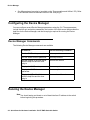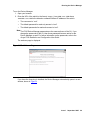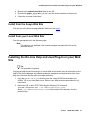
1
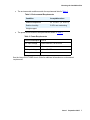
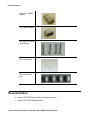
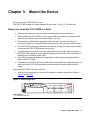
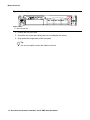
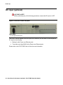
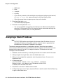
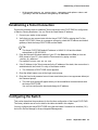
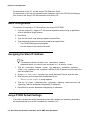
Quick Start for Hardware
Installation
Avaya P333T-PWR Stackable Switch
10-300732
Issue 1
September 2005
Contents
Chapter 1:
Before you Start . . . . . . . . . . . . . . . . . . . . . . . . . . . . . . .
5
Gathering Information . . . . . . . . . . . . . . . . . . . . . . . . . . . . . . . . .
Defining the Installation . . . . . . . . . . . . . . . . . . . . . . . . . . . . . .
Preparing Contacts you might need . . . . . . . . . . . . . . . . . . . . . . .
5
5
5
Preparing Installation Files . . . . . . . . . . . . . . . . . . . . . . . . . . . . . .
6
Preparing Needed Tools . . . . . . . . . . . . . . . . . . . . . . . . . . . . . . . .
6
Choosing the Installation Site . . . . . . . . . . . . . . . . . . . . . . . . . . . .
6
Building a stack . . . . . . . . . . . . . . . . . . . . . . . . . . . . . . . . . . . .
8
Stack Master election rules . . . . . . . . . . . . . . . . . . . . . . . . . . . . . .
10
Chapter 2: Unpack the Device . . . . . . . . . . . . . . . . . . . . . . . . . . . . . .
13
Equipment . . . . . . . . . . . . . . . . . . . . . . . . . . . . . . . . . . . . . . .
13
Documentation. . . . . . . . . . . . . . . . . . . . . . . . . . . . . . . . . . . . .
Avaya P330 Documentation and Utilities CD . . . . . . . . . . . . . . . . . .
14
15
Chapter 3: Mount the Device . . . . . . . . . . . . . . . . . . . . . . . . . . . . . . .
17
Before you Install the P333T-PWR in a Rack. . . . . . . . . . . . . . . . .
17
Chapter 4: Power Up . . . . . . . . . . . . . . . . . . . . . . . . . . . . . . . . . . .
19
AC input . . . . . . . . . . . . . . . . . . . . . . . . . . . . . . . . . . . . . . . .
19
DC input (optional). . . . . . . . . . . . . . . . . . . . . . . . . . . . . . . . . . .
20
Chapter 5: Prepare for Configuration . . . . . . . . . . . . . . . . . . . . . . . . . .
21
Establishing a Console Connection . . . . . . . . . . . . . . . . . . . . . . . . .
21
Assigning a Stack IP Address . . . . . . . . . . . . . . . . . . . . . . . . . . . .
22
Establishing a Telnet Connection. . . . . . . . . . . . . . . . . . . . . . . . . . .
23
Configuring the Switch . . . . . . .
Basic configuration . . . . . . .
Assigning the Stack IP Address
Avaya P333R Default Settings .
.
.
.
.
23
24
24
24
Chapter 6: Device Manager . . . . . . . . . . . . . . . . . . . . . . . . . . . . . . . .
27
Overview . . . . . . . . . . . . . . . . . . . . . . . . . . . . . . . . . . . . . . . .
27
System Requirements . . . . . . . . . . . . . . . . . . . . . . . . . . . . . . . . .
27
Configuring the Device Manager . . . . . . . . . . . . . . . . . . . . . . . . . . .
Device Manager Commands . . . . . . . . . . . . . . . . . . . . . . . . . . .
28
28
Running the Device Manager . . . . . . . . . . . . . . . . . . . . . . . . . . . . .
28
Installing the Java Plug-in. . . . . . . . . . . . . . . . . . . . . . . . . . . . . . .
30
.
.
.
.
.
.
.
.
.
.
.
.
.
.
.
.
.
.
.
.
.
.
.
.
.
.
.
.
.
.
.
.
.
.
.
.
.
.
.
.
.
.
.
.
.
.
.
.
.
.
.
.
.
.
.
.
.
.
.
.
.
.
.
.
.
.
.
.
.
.
.
.
.
.
.
.
.
.
.
.
.
.
.
.
Quick Start for Hardware Installation: P333T-PWR Stackable Switch
.
.
.
.
.
.
.
.
.
.
.
.
September 2005
1
Installing from the P330 Documentation and Utilities CD. . . . . . . . . . . .
Install from the Avaya Web Site . . . . . . . . . . . . . . . . . . . . . . . . .
Install from your Local Web Site . . . . . . . . . . . . . . . . . . . . . . . . .
30
31
31
Installing the On-Line Help and Java Plug-In on your Web Site . . . . . . . . . .
31
Documentation. . . . . . . . . . . . . . . . . . . . . . . . . . . . . . . . . . . . .
32
Quick Start for Hardware Installation: P333T-PWR Stackable Switch
September 2005
2
Quick Start for Hardware Installation: P333T-PWR Stackable Switch
September 2005
3
Copyright 2005, Avaya Inc.
All Rights Reserved
Notice
Every effort was made to ensure that the information in this document
was complete and accurate at the time of printing. However, information
is subject to change.
Warranty
Avaya Inc. provides a limited warranty on this product. Refer to your
sales agreement to establish the terms of the limited warranty. In
addition, Avaya’s standard warranty language as well as information
regarding support for this product, while under warranty, is available
through the following Web site: http://support.avaya.com.
Disclaimer
Avaya is not responsible for any modifications, additions or deletions to
the original published version of this documentation unless such
modifications, additions or deletions were performed by Avaya. Customer
and/or End User agree to indemnify and hold harmless Avaya, Avaya's
agents, servants and employees against all claims, lawsuits, demands
and judgments arising out of, or in connection with, subsequent
modifications, additions or deletions to this documentation to the extent
made by the Customer or End User.
How to Get Help
For additional support telephone numbers, go to the Avaya support Web
site: http://support.avaya.com. If you are:
•
Within the United States, click the Escalation Management
link. Then click the appropriate link for the type of support you
need.
•
Outside the United States, click the Escalation Management
link. Then click the International Services link that includes
telephone numbers for the international Centers of
Excellence.
Standards Compliance
Avaya Inc. is not responsible for any radio or television interference
caused by unauthorized modifications of this equipment or the
substitution or attachment of connecting cables and equipment other
than those specified by Avaya Inc. The correction of interference caused
by such unauthorized modifications, substitution or attachment will be the
responsibility of the user. Pursuant to Part 15 of the Federal
Communications Commission (FCC) Rules, the user is cautioned that
changes or modifications not expressly approved by Avaya Inc. could
void the user’s authority to operate this equipment.
Product Safety Standards
This product complies with and conforms to the following international
Product Safety standards as applicable:
Safety of Information Technology Equipment, IEC 60950, 3rd Edition, or
IEC 60950-1, 1st Edition, including all relevant national deviations as
listed in Compliance with IEC for Electrical Equipment (IECEE) CB-96A.
Safety of Information Technology Equipment, CAN/CSA-C22.2
No. 60950-00 / UL 60950, 3rd Edition, or CAN/CSA-C22.2 No.
60950-1-03 / UL 60950-1.
One or more of the following Mexican national standards, as applicable:
NOM 001 SCFI 1993, NOM SCFI 016 1993, NOM 019 SCFI 1998.
The equipment described in this document may contain Class 1 LASER
Device(s). These devices comply with the following standards:
•
EN 60825-1, Edition 1.1, 1998-01
•
21 CFR 1040.10 and CFR 1040.11.
The LASER devices used in Avaya equipment typically operate within the
following parameters:
Electromagnetic Compatibility (EMC) Standards
This product complies with and conforms to the following international
EMC standards and all relevant national deviations:
Limits and Methods of Measurement of Radio Interference of Information
Technology Equipment, CISPR 22:1997 and EN55022:1998.
Information Technology Equipment – Immunity Characteristics – Limits
and Methods of Measurement, CISPR 24:1997 and EN55024:1998,
including:
•
Electrostatic Discharge (ESD) IEC 61000-4-2
•
Radiated Immunity IEC 61000-4-3
•
Electrical Fast Transient IEC 61000-4-4
•
Lightning Effects IEC 61000-4-5
•
Conducted Immunity IEC 61000-4-6
•
Mains Frequency Magnetic Field IEC 61000-4-8
•
Voltage Dips and Variations IEC 61000-4-11
Power Line Emissions, IEC 61000-3-2: Electromagnetic compatibility
(EMC) – Part 3-2: Limits – Limits for harmonic current emissions.
Power Line Emissions, IEC 61000-3-3: Electromagnetic compatibility
(EMC) – Part 3-3: Limits – Limitation of voltage changes, voltage
fluctuations and flicker in public low-voltage supply systems.
Federal Communications Commission Statement
Part 15:
Note: This equipment has been tested and found to comply with the
limits for a Class A digital device, pursuant to Part 15 of the FCC
Rules. These limits are designed to provide reasonable protection
against harmful interference when the equipment is operated in a
commercial environment. This equipment generates, uses, and can
radiate radio frequency energy and, if not installed and used in
accordance with the instruction manual, may cause harmful
interference to radio communications. Operation of this equipment
in a residential area is likely to cause harmful interference in which
case the user will be required to correct the interference at his own
expense.
Canadian Department of Communications (DOC) Interference
Information
This Class A digital apparatus complies with Canadian ICES-003.
Cet appareil numérique de la classe A est conforme à la norme
NMB-003 du Canada.
European Union Declarations of Conformity
Avaya Inc. declares that the equipment specified in this document
bearing the “CE” (Conformité Europeénne) mark conforms to the
European Union Electromagnetic Compatibility Directive (89/336/EEC)
and Low Voltage Directive (73/23/EEC).
Copies of these Declarations of Conformity (DoCs) can be obtained by
contacting your local sales representative and are available on the
following Web site: http://support.avaya.com.
Japan
This is a Class A product based on the standard of the Voluntary Control
Council for Interference by Information Technology Equipment (VCCI). If
this equipment is used in a domestic environment, radio disturbance may
occur, in which case, the user may be required to take corrective actions.
Typical Center Wavelength Maximum Output Power
830 nm - 860 nm
-1.5 dBm
1270 nm - 1360 nm
-3.0 dBm
1540 nm - 1570 nm
5.0 dBm
Luokan 1 Laserlaite
Klass 1 Laser Apparat
Use of controls or adjustments or performance of procedures other than
those specified herein may result in hazardous radiation exposures.
Contact your Avaya representative for more laser product information.
To order copies of this and other documents:
Call: Avaya Publications Center
Voice 1.800.457.1235 or 1.207.866.6701
FAX 1.800.457.1764 or 1.207.626.7269
Write: Globalware Solutions
200 Ward Hill Avenue
Haverhill, MA 01835 USA
Attention: Avaya Account Management
E-mail: [email protected]
For the most current versions of documentation, go to the Avaya support
Web site: http://support.avaya.com.
Chapter 1: Before you Start
Before you install your Avaya Switch, prepare all the information, resources, and tools that you
need during the installation process. Good preparation ensures a smooth installation with the
least amount of interruption.
!
WARNING:
ONLY TRAINED AND QUALIFIED PERSONNEL SHOULD BE ALLOWED TO
INSTALL OR REPLACE THIS EQUIPMENT.
!
WARNING:
EQUIPMENT MUST BE CONNECTED TO AN EARTHED MAINS
SOCKET-OUTLET.
WARNING:
WARNING:
Gathering Information
Defining the Installation
The P333R can be installed in several different configurations. Before you start the installation,
find out what configuration is needed for your site.
Preparing Contacts you might need
Ensure that you have the names and phone numbers of any people you might need to contact
at the installation site. This list might include the people responsible for:
●
Network architecture
●
System administration
●
Site security
●
Site deliveries
Issue 1 September 2005
5
Before you Start
Preparing Installation Files
Ensure that you load the latest versions of the firmware file for the P333R. You can download
the firmware file needed for your installation from the Avaya Support Web site, at http://
support.avaya.com.
Preparing Needed Tools
Prepare the tools you need to mount the P333T-PWR according to the Table 1:
Table 1: Mounting Tools
If you need to mount on...
Prepare these tools
Rack
Phillips head screwdriver
Choosing the Installation Site
Ensure that the location where you install your P333T-PWR fulfills the following requirements:
●
Cables are away from sources of electrical noise such as:
●
radio transmitters
●
broadcast amplifiers
●
power lines
●
fluorescent light fixtures
●
Water or moisture cannot enter the chassis.
●
Air can flow freely around all sides of the chassis.
●
The vents on the sides of the chassis are not blocked.
6 Quick Start for Hardware Installation: P333T-PWR Stackable Switch
Choosing the Installation Site
●
The environmental conditions match the requirements listed in Table 2.
Table 2: Environmental Requirements
Condition
Acceptable values
Ambient temperature
23o to 122oF (-5o to 50oC)
Relative humidity
5-95% non-condensing
Weight support
●
The power source matches the specifications shown in Table 3:
Table 3: Power Requirements
Power consumption
150 W
AC Input voltage
100 to 240 VAC, 50 to 60 Hz
AC Input current
A
DC Input voltage
-36 to -72 VDC
DC Input current
A max
See the Avaya P333T-PWR User’s Guide for additional information on environmental
requirements.
Issue 1 September 2005
7
Before you Start
Building a stack
Follow the guidelines in this section in order to build a working stack using any combination of
the following devices:
●
P330 series
●
P330-ML series
●
G700
●
P330 series
1. Add only a single box at a time to an existing stack.
!
Important:
Important:
The stack master (also called "stack IP Agent") may fail to preserve existing
"stack configuration" if you will add more than a single device to an existing stack
at a time.
- After adding the first box, wait until the stack is functioning fully before adding the next
device.
2. Refer to Table 4 to see which firmware versions can be used in mixed stacks.
For example, if you wish to add a P332G-ML to a stack with P330 4.5 switches, the
P332G-ML switch must have firmware version 4.5.8.
- Upgrade/downgrade the firmware of switches that do not match version in the table.
Tip:
Tip:
It is highly recommended to upgrade/downgrade before connecting the added
box to an existing stack.
- Ensure switches of the same type have the same firmware version
8 Quick Start for Hardware Installation: P333T-PWR Stackable Switch
Building a stack
Table 4: Firmware Versions Matrix
Required version
Stack without C360
Note:
Stack with C360
Switch
3.11
3.12
4.0
4.1
4.5
4.3
4.5
P333T
3.11.0
3.12.1
4.0.17
4.1.6
4.1.6
N/A
N/A
P334T
3.11.0
3.12.1
4.0.17
4.1.6
4.1.6
N/A
N/A
P333R
3.11.0
3.12.0
4.0.9
4.1.5
4.1.5
N/A
N/A
P333R-LB
3.11.0
3.12.3
4.0.6
4.1.5
4.1.5
N/A
N/A
P332MF
3.11.0
3.12.1
4.0.17
4.1.6
4.1.6
N/A
N/A
P333T-PWR
3.11.0
3.12.1
4.0.17
4.1.6
4.1.6
N/A
4.1.6
G700
3.11.0
3.12.1
4.0.17
4.1.6
4.1.6
N/A
4.1.6
P334T-ML
3.11.16
3.11.16
4.0.15
4.1.3
4.5.8
N/A
N/A
P332G-ML
3.11.15
3.11.15
4.0.15
4.1.3
4.5.8
N/A
4.5.8
P332GT-ML
3.11.15
3.11.15
4.0.15
4.1.3
4.5.8
N/A
4.5.8
C363T
N/A
N/A
N/A
N/A
N/A
4.3.12
4.5.14
C364T
N/A
N/A
N/A
N/A
N/A
4.3.12
4.5.14
C363T-PWR
N/A
N/A
N/A
N/A
N/A
4.3.12
4.5.14
C364T-PWR
N/A
N/A
N/A
N/A
N/A
4.3.12
4.5.14
Note:
Position the C360 switches either at the top or bottom of the stack to ensure
mechanical stability.
Issue 1 September 2005
9
Before you Start
Stack Master election rules
Table 5 lists the switches in order of election priority from highest to lowest.
Note:
Note:
If there are two switches with the same firmware version and the same election
priority, the switch positioned lower in the stack becomes Stack Master.
Table 5: Stack Master election priority
Switch type
Switch mode
Stack Master
election priority
C363T, C363T-PWR
Layer 2
1
C364T, C364T-PWR
Layer 2
2
C363T, C363T-PWR
Layer 3
3
C364T, C364T-PWR
Layer 3
4
P332GT-ML
Layer 2
5
P332G-ML
Layer 2
6
P334T-ML
Layer 2
7
P332GT-ML
Layer 3
8
P332G-ML
Layer 3
9
P334T-ML
Layer 3
10
G700
N/A
11
P333R, P333R-LB
Layer 2
12
P333T, P334T, P332MF
N/A
12
P333T-PWR
N/A
13
P333R, P333R-LB
Layer 3
14
P333R-LB
Webswitch
15
10 Quick Start for Hardware Installation: P333T-PWR Stackable Switch
Stack Master election rules
Figure 1: Example stack elections
C364T-PWR
Layer 3
C363T-PWR
Layer 2
P363T-PWR
Layer 2
P333T
1
P334T-ML
Layer 3
G700
P333T
P334T-ML
Layer 3
G700
1
C363T-PWR
Layer 2
Figure notes:
1. Stack Master
Issue 1 September 2005
11
Before you Start
12 Quick Start for Hardware Installation: P333T-PWR Stackable Switch
Chapter 2: Unpack the Device
!
ELECTROSTATIC ALERT:
ELECTROSTATIC ALERT:
Wear an anti-static wrist ground strap whenever you handle components of a
P333T-PWR Connect the strap to an approved ground, such as an unpainted
metal surface.
Equipment
Open the box that contains the P333T-PWR and ensure that it contains the following
components and accessories:
●
One Avaya P333T-PWR Switch.
●
One Accessory Kit that contains:
One 115V 3 Wire
Power Cable
One RJ45 to RJ45
Flat Cable
Issue 1 September 2005
13
Unpack the Device
One RJ45 to DB9F
Adapter
One DB25M Adapter
Four (4) 5/16" Round
Head Screws
Four (4) Washers
Four (4) stand-off
feet
Documentation
●
Avaya P333T-PWR Quick Start Guide (this document)
●
Avaya P333T-PWR Release Notes
14 Quick Start for Hardware Installation: P333T-PWR Stackable Switch
Documentation
●
Avaya P330 Documentation and Utilities CD (see detail below)
●
Avaya Communication Warranty and License Agreement
Avaya P330 Documentation and Utilities CD
The CD contains the latest User's Guides for the Avaya P330 stackable switches and files for
use with the Embedded Web Manager.
●
User's Guides
You can view and print these Guides using Adobe® Acrobat® Reader.
●
Auxiliary Files for use with the Embedded Web Manager
Please refer to the documentation for information on how to use these files.
- Java plug-in
- Help files
●
Adobe Acrobat Reader
This application allows you to view and print the User's Guides on this CD.
Issue 1 September 2005
15
Unpack the Device
16 Quick Start for Hardware Installation: P333T-PWR Stackable Switch
Chapter 3: Mount the Device
You can mount the P333T-PWR in a rack.
The P333T-PWR chassis fits in most standard 19-inch racks. It is 2U (3.5”, 88 mm) high.
Before you Install the P333T-PWR in a Rack
●
Disconnect all cables from the unit before proceeding with the rack installation.
●
When installing the P333T-PWR in a rack, ensure that the equipment is positioned such
that it will not cause the rack to become unstable or tip over.
●
Ensure that the combination of equipment in the rack will not cause an overload or
overcurrent condition on the power strip being used and/or the customer's branch circuit.
●
The P333T-PWR units weigh a maximum of 15 pounds (6.8 kg). Be careful when installing
or removing the P333T-PWR product from the rack.
●
If a power strip is being used in the rack, ensure that it has a reliable earth connection. If
the P333T-PWR equipment will be plugged directly into a wall outlet, ensure that there is a
reliable ground connection at the outlet.
●
Ensure that the internal rack ambient temperature is within the operating specification
limits of the P333T-PWR.
●
Ventilation for the P333T-PWR is from side to side. Ensure that there is adequate space on
each side of the P333T-PWR equipment when installed in the rack to allow sufficient
airflow.
Place the P333T-PWR in the rack as follows:
1. Snap open the hinged ends of the unit’s front panel to reveal the screw holes. Refer to
Figure 2 and Figure 3.
Figure 2: Closed hinged end
P333R
51 52 53 54
55 56 57 58
59 60 61 62
63 64 65 66
1
2
3
4
5
6
7
8
9
10 11 12
EXPANSION
SLOT
FIV
13 14 15 16
LNK COL Tx
17 18 19 20
Rx FDX FC Hspd LAG
21 22 23 24
ROUT
SYS OPR PWR
LAG
1
2
LAG
3
4
5
6
LAG
7
8
9
10
11
12
CONSOLE
1
13
14
15
16
17
18
19
20
21
22
23
24
Figure notes:
1. Closed hinged end
Issue 1 September 2005
17
Mount the Device
Figure 3: Open hinged end
P333R
51 52 53 54
55 56 57 58
59 60 61 62
63 64 65 66
1
2
3
4
5
6
7
8
9
10 11 12
EXPANSION
SLOT
FIV
13 14 15 16
LNK COL Tx
17 18 19 20
Rx FDX FC Hspd LAG
1
21 22 23 24
ROUT
SYS OPR PWR
LAG
1
2
LAG
3
4
5
6
LAG
7
8
9
10
11
12
CONSOLE
13
14
15
16
17
18
19
20
21
22
23
24
Figure notes:
1. Open hinged end
2. Position the unit in the rack.
3. Secure the unit to the rack, taking care not to overtighten the screws.
4. Snap closed the hinged ends of the front panel.
Tip:
Tip:
You can now safely connect the cables to the unit.
18 Quick Start for Hardware Installation: P333T-PWR Stackable Switch
Chapter 4: Power Up
Connecting the P333T-PWR to the main electrical supply provides power to the switch.
!
VOLTAGE ALERT:
VOLTAGE ALERT:
To isolate the switch completely, you must disconnect all power connections: AC
plug or DC terminal block and DC BUPS power.
AC input
1. Insert the power cord into the power connector (BUPS or Power Supply) on the rear of the
unit.
Figure 4: P333T-PWR rear panel
1
2
Figure notes:
1. BUPS connector
2. AC connector
2. Insert the other end of the power cord into the electricity supply or the BUPS connector.
- The unit powers up and performs a self test procedure. The LEDs flash at regular
intervals after the self-test procedure is completed successfully.
Issue 1 September 2005
19
Power Up
DC input (optional)
!
VOLTAGE ALERT:
VOLTAGE ALERT:
Before performing any of the following procedures, ensure that DC power is OFF.
Figure 5: P333R DC version rear panel
1
Figure notes:
1. DC input terminal block
The P333T-PWR an operate on the AC input only. However, you may wish to use the optional
DC input for the following:
●
Backup for the Power over Ethernet ports
●
To provide more than 200W for the Power over Ethernet ports
Please refer to the P333T-PWR User’s Guide for more information.
20 Quick Start for Hardware Installation: P333T-PWR Stackable Switch
Chapter 5: Prepare for Configuration
This chapter provides information on preparing the P333R for configuration, and discusses the
following topics:
●
Establishing a Console Connection
●
Assigning a Stack IP Address
●
Establishing a Telnet Connection
●
Configuring the Switch
Establishing a Console Connection
This section describes the procedure for establishing switch access between a terminal and the
Avaya P333T-PWR switch over the serial port provided on the front panel of the P333T-PWR
(RJ-45 connector labeled “Console”). For information on the console port pin assignments, refer
to the Avaya P333T-PWR User Guide.
Figure 6: Avaya P333T-PWR Console Port
1
Figure notes:
1. Console port
1. Use the serial cable supplied to attach the RJ-45 console connector to the Console port of
the active switch. Connect the DB-9 connector to the serial (COM) port on your PC/
terminal.
- The master switch is indicated by the SYS LED being ON.
2. Ensure that the serial port settings on the terminal are:
Issue 1 September 2005
21
Prepare for Configuration
●
9600 baud
●
8 bits
●
1 stop bit
●
no parity.
- If you reset or powered up the switch after connecting and configuring the terminal,
Welcome to P333T-PWR appears followed by the Login Name prompt.
- If the login prompt does not appear, press a key on the terminal.
3. Enter the default login: root.
- The Password prompt appears
4. Enter the user level password: root.
- You can now establish a connection to the Router or the Master switch (indicated
when the SYS front panel LED is ON) using the Session commands and begin the
configuration of module, stack, or router parameters.
Assigning a Stack IP Address
Note:
Note:
All P333T-PWR switches are shipped with the same default IP address. You must
change the IP address of the master switch in a stack in order to guarantee that
the stack has its own unique IP address in the network.
The network management station or a workstation running a Telnet client can establish
communications with the stack once this address had been assigned and the stack has been
inserted into the network. Use the CLI to assign the stack an IP address and net mask.
To assign an IP stack address:
1. Establish a serial connection by connecting a terminal to the master switch of the stack.
2. When prompted for a Login Name, enter the default name root
3. When you are prompted for a password, enter the password root. You are now in
Supervisor Level.
4. At the prompt, type:
set interface inband <vlan> <ip_address> <netmask>
Replace <vlan>, <ip_address> and <netmask> with the VLAN,
IP address, and net mask of the stack.
5. Press Enter to save the IP address and net mask.
6. At the prompt, type reset. Type y and press Enter to reset the stack. After the Reset, log
in again as described above.
22 Quick Start for Hardware Installation: P333T-PWR Stackable Switch
Establishing a Telnet Connection
- At the prompt, type set ip route <dest> <gateway> and replace <dest> and
<gateway> with the destination and gateway IP addresses.
Establishing a Telnet Connection
Perform the following steps to establish a Telnet connection to the P333T-PWR for configuration
of Stack or Router parameters. You can Telnet the Stack Master IP address:
1. Connect your station to the network.
2. Verify that you can communicate with the Avaya P333T-PWR by pinging the IP of the
Avaya P333T-PWR. If there is no response using ping, check the IP address and default
gateway of both the Avaya P333T-PWR and the station.
Tip:
The Avaya P333T-PWR default IP address is 149.49.32.134 and the default
subnet mask is 255.255.255.0.
Tip:
3. From the Microsoft Windows taskbar of your PC click Start and then Run (or from the
DOS prompt of your PC), then start the Telnet session by typing: telnet
<P333R_IP_address>
For example: telnet 149.49.32.134
4. If the IP Address in the Telnet command is the IP address of the stack, then connection is
established with the Switch CLI entity of the Master module.
●
The “Welcome to P333T-PWR screen appears
5. Enter the default name root at the Login name prompt.
6. Enter the User Level password root in lower case letters (do not use uppercase letters) at
the Password prompt.
●
The User level prompt will appear when you have established communications with
the Avaya P333T-PWR
You can now configure the stack and change its IP address.
Configuring the Switch
This section describes the procedures for the first-time configuration of the Avaya P333T-PWR
The factory defaults are set out in detail in the tables included in this chapter.
You may configure the Avaya P333T-PWR using the text-based Command Line Interface (CLI),
the built-in Device Manager or Avaya Integrated Management.
Issue 1 September 2005
23
Prepare for Configuration
For instructions on the CLI, see the Avaya P330 Reference Guide.
For instructions on the use of the graphical user interfaces, refer to the P330 Device Manager
User Guide on the Avaya P330 Documentation and Utilities CD.
Basic configuration
To connect a PC terminal or VT-100 terminal to the Avaya P333T-PWR
1. If you are using a PC, initiate a VT-100 terminal emulation session using an application
such as Windows® HyperTerminal.
2. Press Enter.
3. Type the User name root when prompted and press Enter.
4. Type the default password root when prompted and press Enter.
- The P333R-N(super)# prompt appears
N is the number of the switch in the stack.
Assigning the Stack IP Address
Tip:
Tip:
Commands are shown as follows: set interface inband;
parameters which you need to enter are shown in <> as follows: <vlan>
1. Type set interface inband <vlan> <ip_address> <netmask>, replacing
<vlan>, <ip_address> and <netmask> with the VLAN, IP address and net mask of the
stack and press Enter.
2. At the P333T-PWR(super)# prompt, type reset and press Enter to reset the stack.
3. After the reset, perform login again as described above.
- The P333T-PWR(super)# prompt appears.
4. Type set ip route <destination> <gateway>, replacing <destination> and
<gateway> with the destination and gateway IP addresses.
5. Press Enter to save the destination and gateway IP addresses.
Avaya P333R Default Settings
If you wish to change the default parameters shown and configure the mandatory parameters,
we recommend that you use the Command Line Interface (CLI).
24 Quick Start for Hardware Installation: P333T-PWR Stackable Switch
Configuring the Switch
For further information, please refer to Chapter 6 of the Avaya P333T-PWR User’s Guide.
The default settings for the Avaya P333T-PWR switch and its ports are determined by the
Avaya P333T-PWR firmware. These default settings are subject to change in newer versions of
the Avaya P333T-PWR firmware. See the P330 Release Notes for the most up-to-date settings.
Table 6: Default Switch Settings
Function
Default Setting
IP address
149.49.32.134
BootP mode
Never
Subnet Mask
255.255.255.0
Default gateway
0.0.0.0
Management PC SLIP IP Address
192.168.10.2
Management VLAN ID
1
Spanning tree
Enabled
TFTP Mode
Limited
TFTP Server
0.0.0.0
TFTP File Name
viisa
SNMPv1 communities:
Read-only
Read-write
Trap SNMP
Public
Public
Public
SNMP authentication trap
Disabled
CLI timeout
15 Minutes
User Name/Password
root/root
Issue 1 September 2005
25
Prepare for Configuration
Table 7: Default Port Settings
Parameter
Default Setting
Port speed and duplex mode
●
●
●
Flow Control
●
●
Backpressure
●
●
Auto-negotiation
●
●
●
Tip:
10/100-TX ports: Auto-negotiation
100Base-FXports:100 Mbps full duplex
1000Base-X ports: 1000 Mbps full duplex
10/100 and 100 Mbps: Disabled
1000 Mbps: Disabled (no pause)
10/100: Enabled (when in half duplex mode)
100Base-FX &1000 Mbps: Not applicable
10/100-TX ports: Enabled
100Base-FX ports: Not applicable
1000Base-X ports: Enabled
Administration State
Enabled
Port VLAN ID
1
Tagging mode
Clear
Port priority
Regular
Inline power
Enabled
Inline power priority
Low
Tip:
Functions operate in their default settings unless configured otherwise.
26 Quick Start for Hardware Installation: P333T-PWR Stackable Switch
Chapter 6: Device Manager
This chapter describes the installation procedures for the Device Manager.
Overview
The Device Manager provides the following:
●
Managing and monitoring Power over Ethernet.
●
Device Configuration - Viewing and modifying the different device configurations.
●
Virtual LANs - Viewing and editing Virtual LAN information.
●
Link Aggregation Groups (LAGs) - Viewing and editing LAG information.
●
Port Redundancy - Setting port redundancy for ports in a P333T-PWR Switch.
●
Port Mirroring - Setting up port mirroring for ports in a P333T-PWR Switch.
●
Trap Managers Configuration - Viewing and modifying the Trap Managers Table.
●
Switch Connected Addresses - View devices connected to selected ports.
●
Port Security.
●
Intermodule Redundancy
●
One pair per stack.
●
Also operates as a result of a module fault, for example, power failure.
System Requirements
Minimum hardware and operating system requirements are:
●
Pentium II 400 Mhz-based computer with 128 Mb of RAM.
●
Screen resolution of 1024 x 768 pixels.
●
Microsoft Internet Explorer 5 or higher.
●
Microsoft Windows 2000 Workstation or Windows XP.
Issue 1 September 2005
27
Device Manager
●
Sun Microsystems Java plug-in (supplied on the “Documentation and Utilities” CD). Refer
to the Release Notes for the exact version of the Java plug-in.
Configuring the Device Manager
You can configure several Device Manager parameters using the CLI. These parameters
include the time-out and retries parameters, the location of the Web server that provides the
help files for the Device Manager, and the Java plug-in required for running the Device
Manager.
Device Manager Commands
The following Device Manager commands are available.
In order to...
Use the following command...
Set the SNMP retries parameter
set snmp retries
Set the SNMP time-out parameter
set snmp time-out
Set the location of the Web server
with the help files and the Java
plug-in
set web aux-files-url
Display the SNMP retries parameter
show snmp retries
Display the SNMP time-out
parameter
show snmp time-out
Display the URL of the Web server
with the help files and the Java
plug-in
show web aux-files-url
Running the Device Manager
Note:
Note:
You should assign an inband or out-of-band interface IP address to the switch
before beginning this procedure.
28 Quick Start for Hardware Installation: P333T-PWR Stackable Switch
Running the Device Manager
To run the Device Manager:
1. Open your browser.
2. Enter the URL of the switch in the format http://aaa.bbb.ccc.ddd where
aaa.bbb.ccc.ddd is the inband or outband interface IP address of the switch.
- The user name is “root”.
- The default password for read-only access is “root”.
- The default passwords for read-write access is “root”.
Note:
Note:
The P330 Device Manager passwords are the same as those of the CLI. If you
change the passwords of the CLI then those passwords become active for the
Device Manager as well. For further information on the passwords, refer to the
Avaya P330 Installation and Configuration User Guide.
The welcome page is displayed.
Figure 7: The Welcome Page
If you have the Java plug-in installed, the Device Manager automatically opens in a new
window, shown in Figure 8.
Issue 1 September 2005
29
Device Manager
Figure 8: Device Manager
3. If you do not have the Java plug-in installed, follow the instructions on the Welcome page
for a variety of options to install the plug-in (see Installing the Java Plug-in).
Installing the Java Plug-in
If the network manager has configured the system, the plug-in should be installed automatically.
Note:
Ensure that Java or JavaScript is enabled on your Web browser. Please refer to
your browser on-line help or documentation for further information.
Note:
If the plug-in is not installed automatically, then you have three options for installing it manually:
●
Installing from the P330 Documentation and Utilities CD
●
Install from the Avaya Web Site
●
Install from your Local Web Site
Installing from the P330 Documentation and Utilities CD
To install from the P330 Documentation and Utilities CD:
1. Close all unnecessary applications on your PC.
2. Insert the Avaya P330 Documentation and Utilities CD in the CD drive.
3. Open Windows Explorer.
30 Quick Start for Hardware Installation: P333T-PWR Stackable Switch
Installing the On-Line Help and Java Plug-In on your Web Site
4. Browse to the embweb-aux-files\ folder on the CD.
5. Double-click plugin_a_b_c.exe (a, b and c are the version numbers of the plug-in).
6. Follow the on-screen instructions.
Install from the Avaya Web Site
Click the link in the Welcome page labelled “Retrieve it from here”.
Install from your Local Web Site
Click the appropriate link in the Welcome page.
Note:
Note:
This option is only available if the network manager has placed the files on the
local Web server.
Installing the On-Line Help and Java Plug-In on your Web
Site
Tip:
Tip:
This procedure is optional.
Copying the help files and Java plug-in to a local Web server allows users to access the on-line
help for the Device Manager and enables automatic installation and maintenance of the Java
plug-in the first time the user tries to manage the device.
1. Copy the emweb-aux-files directory from the “Avaya P330 Documentation and
Utilities” CD to your local Web server. Refer to your Web server documentation for full
instructions.
2. Define the URL in the P333T-PWR using the following CLI command:
set web aux-files-url //IP address/directory name
where //IP address/directory name is the location of the directory from the
previous step.
Issue 1 September 2005
31
Device Manager
Documentation
The Device Manager comes with a detailed User’s Guide including a Glossary of Terms and an
overview of Data Communications concepts.
32 Quick Start for Hardware Installation: P333T-PWR Stackable Switch