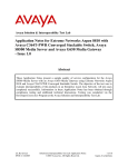
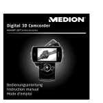
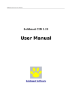
1
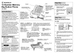
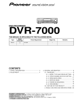
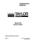
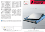
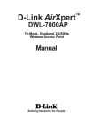
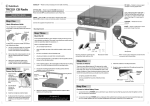
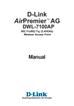
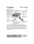
Avaya Solution & Interoperability Test Lab
Application Notes for Configuring Aruba 5000 and 2400
Wireless LAN Switches to Support Avaya Communication
Manager, Avaya IP Wireless Telephone and Avaya IP
Softphone - Issue 1.0
Abstract
These Application Notes describe the procedure for configuring the Aruba Wireless LAN
Switches to support Avaya Communication Manager, Avaya IP Wireless Telephone and IP
Softphone. Features and functionality were validated and performance testing was conducted
in order to verify their operation under load. Information in these Application Notes has been
obtained through compliance testing and additional technical discussions. Testing was
conducted via the DeveloperConnection Program at the Avaya Solution and Interoperability
Test Lab.
SZ; Reviewed:
WCH 11/24/2004
Solution & Interoperability Test Lab Application Notes
©2004 Avaya Inc. All Rights Reserved.
1 of 23
Aruba-wireless.doc
1. Introduction
These Application Notes describe a compliance-tested configuration comprising of Aruba 5000
and 2400 Wireless LAN Switches. Aruba designs the wireless LAN switches for distributive
network infrastructure. The basic infrastructure consists of a master switch, Aruba 5000, and a
remote switch, Aruba 2400. All wireless related configurations are done on the master switch
and the configuration is then pushed to all remote switches. The Aruba Access Point (AP)
supports 802.11a/b/g modes. These Application Notes cover the following areas:
Layer 2 and Layer 3 switch configuration, including VLANs, 802.1Q Tagging and Static
IP routing.
Quality of Service, including configuration of QoS polices in 802.1p and DiffServ.
802.1 x authentications with WEP encryption.
Wireless 802.11 a/b/g mode configurations.
These Application Notes do not cover the configuration for Avaya IP wireless telephones, Avaya
IP Softphone or Odyssey RADIUS Server and clients. For detailed configuration of these
devices, refer to the Application Notes listed in the Section 10.
SZ; Reviewed:
WCH 11/24/2004
Solution & Interoperability Test Lab Application Notes
©2004 Avaya Inc. All Rights Reserved.
2 of 23
Aruba-wireless.doc
Figure 1 shows the network configuration used for verification.
VLAN 1
Avaya
G650 Media
Gateway
VLAN 3
DHCP/Odyssey
Radius Server
Avaya IP
Softphone 1
x47005
Avaya S8500
Media Servers
Avaya
Wireless 3616
Telephone 1
x47001
10.1.2.20
10.1.2.5
Aruba AP1
10.1.2.9
Avaya Voice
Priority
Processor
Avaya Wireless
3626 Telephone 2
x47002
10.3.3.2
10.4.4.1
10.3.3.1
Extreme 3804
Aruba 2400
Avaya IP
Softphone 2
x47006
VLAN 4
Avaya 4620SW
IP Telephone 1
x47003
Avaya Wireless
3616 Telephone 3
x47004
10.4.4.2
Aruba AP2
Aruba 5000
Avaya 4610SW
IP Telephone 2
x47007
Figure 1: Network Configuration
SZ; Reviewed:
WCH 11/24/2004
Solution & Interoperability Test Lab Application Notes
©2004 Avaya Inc. All Rights Reserved.
3 of 23
Aruba-wireless.doc
Table 1 lists the IP addresses and subnet masks for the tested devices.
Device
S8500 Media Server
G650 Gateway
• IPSI
• C-LAN
• MEDPRO
Avaya Voice Priority
Processor
Aruba 5000
VLAN
VLAN 1
VLAN 1
Aruba 2400
Aruba Access Point 1
Aruba Access Point 2
Extreme Alpine 3804
Odyssey RADIUS Server
IP Address/Mask
10.1.2.5 /24
Gateway
10.1.2.1
VLAN 1
10.1.2.6/24
10.1.2.7/24
10.1.2.8/24
10.1.2.9/24
10.1.2.1
10.1.2.1
10.1.2.1
10.1.2.1
VLAN 4
VLAN 4000
Loopback
VLAN 3
VLAN 4000
Loopback
VLAN 4000
VLAN 4000
VLAN1
VLAN3 (to Aruba 2400)
VLAN4 (to Aruba 5000)
VLAN 1
10.4.4.2/24
172.16.2.1/24
10.4.4.3/24
10.3.3.2/24
172.16.2.2/24
10.3.3.3/24
172.16.2.3/24
172.16.2.4/24
10.1.2.1/24
10.3.3.1/24
10.4.4.1/24
10.1.2.20/24
10.4.4.1
10.3.3.1
172.16.2.2
172.16.2.1
10.1.2.1
2. Equipment and Software Validated
Table 2 lists the equipment and software version used for the configuration.
Equipment
Avaya S8500 Media Server/G650 Media Gateway with
Avaya IP Softphone
Avaya 4620SW/4610SW IP telephones
Avaya 3616/3626Wireless IP Phone
Avaya Voice Priority Processor
Aruba 5000 Wireless LAN Switch
Aruba 2400 Wireless LAN Switch
Extreme Alpine 3804 Switch
Dell Laptop with
Windows 2000 Professional with SP4
D-Link DWL-AG650 Wireless Card
Dell Laptop with
Windows XP Professional with SP1
Intel PRO/Wireless LAN 2100 3A Mini PCI
Adapter
Odyssey RADIUS Server
SZ; Reviewed:
WCH 11/24/2004
Software
Communication Manager
2.0.1 (R012x.00.1.221.1)
V5.0.1.2
R2.01
96.024
R32/21
V2.0.6.0
V2.0.6.1
V7.2.0b25
5.00.2195
V1.2.0.1
V2002
V7.1.0.0
V2.01.00.653
Solution & Interoperability Test Lab Application Notes
©2004 Avaya Inc. All Rights Reserved.
4 of 23
Aruba-wireless.doc
3. Configure the Aruba 5000 and 2400 Wireless LAN
Switches
The switch configuration can be done using either a web-based interface or a command line
interface (CLI). The following sessions display the configuration using CLI. For web-based
configuration, refer to the Aruba 5000 and 2400 switch configuration guide. The Aruba 5000
switch is configured as a master switch and the Aruba 2400 is configured as a remote switch.
3.1. Configure Aruba 5000 Wireless LAN Switch
Step
1.
Description
Enter command configure t from the switch console to get into the configuration mode.
Note: Since there is significant system control information exchanged between the master and
remote switches, it is recommended to have a separate VLAN to carry this traffic instead of
sharing the VLAN with VoIP traffic. In this configuration, VLAN 4000 was created for this
purpose.
Configure VLAN, Port Tagging
VLAN 4
VLAN 4000
-- create VLANs in the master switch
interface fastethernet 2/0
-- switch port connected to the Extreme Switch
trusted
switchport mode trunk
switchport trunk allowed VLAN 4
!
interface fastethernet 2/1
-- switch port connected to the IP Telephone
trusted
switchport access VLAN 4
spanning-tree portfast
interface fastethernet 2/2
trusted
switchport access VLAN 4000
!
-- switch port connected to the AP
Configure VLAN interface, IP address and Default Gateway
2.
interface VLAN 4
ip address 10.4.4.2 255.255.255.0
interface VLAN 4000
ip address 172.16.2.1 255.255.255.0
interface loopback
ip address 10.4.4.3 255.255.255.0
ip default-gateway 10.4.4.1
SZ; Reviewed:
WCH 11/24/2004
Solution & Interoperability Test Lab Application Notes
©2004 Avaya Inc. All Rights Reserved.
5 of 23
Aruba-wireless.doc
Step
3.
Description
Configure QoS policy
ip access-list session soft-phone
any any udp 2048 3028 permit queue high
any any tcp 1719 1720 permit queue high
any any udp 1719 1720 permit queue high
ip access-list session hard-phone
any any 119 permit queue high
-- match the udp port range in
ip-network-region
-- send call control traffic into high queue
-- protocol 119 is the SpectraLink protocol for Avaya
IP wireless telephone
user-role voice
session-acl control
session-acl soft-phone
session-acl hard-phone
!
aaa derivation-rules user
set role condition essid equals AAA set-value voice
4.
Configure 802.1x authentication and encryption
aaa radius-server odyssey host 10.1.2.80 key xxxxxxxxx
aaa dot1x mode enable
dot1x re-authentication
dot1x multicast-keyrotation
dot1x unicast-keyrotation
aaa dot1x default-role voice
aaa dot1x auth-server odyssey
Configure 802.11 a/b/g radio
5.
ap location 0.0.0
essid "AAA"
max-clients 25
opmode dynamicTkip
VLAN-id 4
ap location 2.0.0
lms-ip 172.16.2.1
phy-type a
VLAN-id 3
phy-type b
vlan-id 3
SZ; Reviewed:
WCH 11/24/2004
Solution & Interoperability Test Lab Application Notes
©2004 Avaya Inc. All Rights Reserved.
6 of 23
Aruba-wireless.doc
3.2. Configure Aruba 2400 Wireless LAN Switch
Step
1.
Description
Configure VLAN, Port Tagging
VLAN 3
VLAN 4000
interface fastethernet 1/0
trusted
switchport mode trunk
switchport trunk allowed VLAN 3
interface fastethernet 1/1
trusted
switchport access VLAN 4000
2.
Configure VLAN interface, IP address and Default Gateway
interface VLAN 3
ip address 10.3.3.2 255.255.255.0
interface VLAN 4000
ip address 172.16.2.2 255.255.255.0
interface loopback
ip address 10.3.3.3 255.255.255.0
ip default-gateway 10.3.3.1
masterip 10.4.4.2
-- configure the master switch (Aruba 5000) IP address so that the remote
switch (Aruba 2400) knows from where to download the configuration
file.
3.3. Configure Aruba Access Points
Access Point configuration is done via the serial port. Connect a computer serial port to the AP’s
serial port and launch a terminal emulator with the following settings:
• Bits per second 9600
• Data bits
8
• Parity
None
• Stop bits
1
• Flow control
None
When the AP is powered up, break the boot sequence with <ctrl-c> to get into the configuration
mode.
SZ; Reviewed:
WCH 11/24/2004
Solution & Interoperability Test Lab Application Notes
©2004 Avaya Inc. All Rights Reserved.
7 of 23
Aruba-wireless.doc
Step
1.
Description
Configure Access Point 1 (AP1)
Setenv
Setenv
Setenv
Setenv
Setenv
Setenv
ipaddress 172.16.2.2
netmask 255.255.255.0
gatewayip 172.16.2.1
serverip 10.3.3.3
master 10.4.4.3
location 2.1.1
-- using master switch’s (5000) loopback IP Address
save
2.
Configure Aruba Access Point 2 (AP2)
Setenv
Setenv
Setenv
Setenv
Setenv
Setenv
save
ipaddress 172.16.1.2
netmask 255.255.255.0
gatewayip 172.16.1.1
serverip 10.4.4.3
master 10.4.4.3
location 1.1.1
-- using master switch’s (5000) loopback IP Address
4. Configure the Avaya Wireless Voice Priority Processor
The Avaya Wireless Voice Priority Processor (AVPP) functions as a wireless VoIP gateway and
provides voice priority service for IP wireless telephones. The following steps describe the
configuration. Note each IP network (sub-net) requires one AVPP.
Step
1.
2.
Description
Using a console cable, connect the AVPP to the PC.
Start a HyperTerminal session to the AVPP.
• Bits per second 9600
• Data bits
8
• Parity
None
• Stop bits
1
• Flow control
None
SZ; Reviewed:
WCH 11/24/2004
Solution & Interoperability Test Lab Application Notes
©2004 Avaya Inc. All Rights Reserved.
8 of 23
Aruba-wireless.doc
Step
3.
Description
Provide the User Name and Password to access the AVPP.
• The Gateway Connection Selection window will be displayed.
NetLink SVP-II System
Hostname: [slnk_00d07e], Address: 0.0.0.0
System Status
SVP-II Configuration
Network Configuration
Change Password
Exit
Enter=Select
4.
X=Exit
Use Arrow Keys to Move Cursor
Select Network Configuration and press Enter.
The Network Configuration window will be displayed.
• Provide the following information:
o IP Address = 10.1.2.9
o Subnet Mask = 255.255.255.0
o Default Gateway = 10.1.2.1
Network Configuration
Hostname: [slnk_00d07e], Address: 0.0.0.0
Ethernet Address (fixed):
IP Address:
Hostname:
Subnet Mask:
Default Gateway:
SVP-II TFTP Download Master:
Primary DNS Server:
Secondary DNS Server:
DNS Domain:
WINS Server:
Workgroup:
Syslog Server:
Maintenance Lock:
Enter=Change
•
SZ; Reviewed:
WCH 11/24/2004
Esc=Exit
00:90:7A:00:D0:7E
10.1.2.9
slnk_00d07e
255.255.255.0
10.1.2.1
NONE
NONE
NONE
NONE
NONE
WORKGROUP
NONE
N
Use Arrow Keys to Move Cursor
Press Enter
Solution & Interoperability Test Lab Application Notes
©2004 Avaya Inc. All Rights Reserved.
9 of 23
Aruba-wireless.doc
Step
5.
Description
On the NetLink SVP-II System window:
•
Select SVP-II Configuration, and press Enter.
NetLink SVP-II System
Hostname: [slnk_00d07e], Address: 10.1.2.9
System Status
SVP-II Configuration
Network Configuration
Change Password
Exit
Enter=Select
6.
X=Exit
Use Arrow Keys to Move Cursor
On the SVP-II Configuration window:
•
Select Reset System, and press Enter.
This will reconfigure the AVPP with current settings.
SVP-II Configuration
Hostname: [slnk_00d07e], Address: 10.1.2.9
Phones per Access Point:
SVP-II Mode:
System Locked:
Maintenance Lock:
Reset System
Enter=Change
SZ; Reviewed:
WCH 11/24/2004
Esc=Exit
5
Netlink IP
N
N
Use Arrow Keys to Move Cursor
Solution & Interoperability Test Lab Application Notes
©2004 Avaya Inc. All Rights Reserved.
10 of 23
Aruba-wireless.doc
5. Configure the Avaya S8500 Media Server with the Avaya
G650 Media Gateway
This section describes the steps necessary to configure the Avaya S8500 Media Server with a
G650 Media Gateway.
5.1. Configuring the Ethernet Interfaces of the Avaya S8500 Media
Servers
The Avaya S8500 Media Server is configured using a web interface. To access the web interface,
connect a computer’s Ethernet interface to the services port of the Avaya S8500 Media Server
with a crossover Ethernet cable. The services port uses the pre-configured IP address 192.11.13.6
with mask 255.255.255.252. Configure the computer’s IP address as 192.11.13.5 with mask
255.255.255.252. Connect the computer’s Ethernet interface to the services port with a crossover
Ethernet cable. Launch a web browser with the URL http://192.11.13.6. After logging in, click
Launch Maintenance Web Interface to get to the main menu on the left hand side. Click
Configure Server from the lower left of this main menu.
The Avaya S8500 Media Server has two IP interfaces. Ethernet 1 is used for the control network
to communicate with the IPSI circuit pack of the Avaya G650 Media Gateway. Ethernet 2 is
dedicated to the services port.
SZ; Reviewed:
WCH 11/24/2004
Solution & Interoperability Test Lab Application Notes
©2004 Avaya Inc. All Rights Reserved.
11 of 23
Aruba-wireless.doc
Step
1.
Description
Configuring S8500 Media Server
•
•
Click Set Identities and enter the information shown below.
Click Continue.
SZ; Reviewed:
WCH 11/24/2004
Solution & Interoperability Test Lab Application Notes
©2004 Avaya Inc. All Rights Reserved.
12 of 23
Aruba-wireless.doc
Step
2.
Description
Configuring S8500 Media Server Interfaces
•
•
Click Configure Interfaces and enter the information shown below.
Click Continue.
5.2. Configuring IPSI on the Avaya G650 Media Gateway
The IP address of an IPSI board has to be configured via its services port. To configure the IPSI
board, connect the computer (already configured with the services IP address and mask as above)
to the services port of the IPSI. Telnet to 192.11.13.6 and supply the appropriate login
credentials. The following screenshot illustrates the appropriate commands. The IPSI IP address
is configured to 10.1.2.6 with default gateway 10.1.2.1.
SZ; Reviewed:
WCH 11/24/2004
Solution & Interoperability Test Lab Application Notes
©2004 Avaya Inc. All Rights Reserved.
13 of 23
Aruba-wireless.doc
Step
1.
Description
Configuring IPSI
TN2312 IPSI IP Admin Utility
Copyright Avaya Inc, 2000, 2001, All Rights Reserved
[IPSI]: ipsilogin
Login: craft
Password:
[IPADMIN]: set control interface 10.1.2.6 255.255.255.0
WARNING!! The control network interface will change upon exiting IPADMIN
[IPADMIN]: set control gateway 10.1.2.1
WARNING!! The control network interface will change upon exiting IPADMIN
[IPADMIN]: set VLAN tag off
[IPADMIN]: set diffserv 46
[IPADMIN]: show control interface
Control
Control
Control
IPSI is
Network IP Address = 10.1.2.6
Network Subnetmask = 255.255.255.0
Network Default Gateway = 10.1.2.1
not configured for DHCP IP address administration
[IPADMIN]: show qos
QoS values currently in use:
VLAN tagging
:
VLAN id
:
VLAN user priority :
Diffserv value
:
off
0
6
46
5.3. Configuring the Avaya S8500 Media Servers for the Avaya G650
Media Gateway
This section presents the relevant configuration of the Avaya Communication Manager software.
The Avaya Communication Manager SAT screens can be accessed using “telnet 192.11.13.6
5023” from a computer connected to the server’s services port, or “telnet 10.1.2.5 5023” through
the control network.
SZ; Reviewed:
WCH 11/24/2004
Solution & Interoperability Test Lab Application Notes
©2004 Avaya Inc. All Rights Reserved.
14 of 23
Aruba-wireless.doc
Step
1.
Description
Enable IPSI
Use the command change system-parameters ipserver-interface to globally enable the
server to control the IPSI installed in slot A1 on the gateway. Set the field IPSI Control of
Port Networks to enabled as shown below.
change system-parameters ipserver-interface
IP SERVER INTERFACE (IPSI) SYSTEM PARAMETERS
SERVER INFORMATION
IPSI Host Name Prefix:
Primary Control Subnet Address:
Secondary Control Subnet Address:
.
.
.
.
.
.
OPTIONS
Switch Identifier: A
IPSI Control of Port Networks: enabled
2.
Add Cabinet
Use the command add cabinet X (X is the cabinet number) to add a cabinet for the G650
gateway. Cabinet Layout must be configured as G650-rack-mount-stack for the Avaya
G650 Media Gateway.
add cabinet 1
Page
1 of
1
CABINET
CABINET DESCRIPTION
Cabinet: 1
Cabinet Layout: G650-rack-mount-stack
Cabinet Type: expansion-portnetwork
Location: 1
Rack:
Room:
CARRIER DESCRIPTION
Carrier
Carrier Type
E
D
C
B
A
3.
Floor:
Building:
Number
not-used
not-used
not-used
not-used
G650-port
Add G650 Media Gateway
Use the command add ipserver-interface X (X is the cabinet number) to add a G650 Media
Gateway. Type the IPSI IP address (10.1.2.6 in this sample configuration) in the Host field.
SZ; Reviewed:
WCH 11/24/2004
Solution & Interoperability Test Lab Application Notes
©2004 Avaya Inc. All Rights Reserved.
15 of 23
Aruba-wireless.doc
Step
Description
The following displays the ipserver-interface configuration. Note that QoS parameters are
configured for the communication from the Avaya S8500 Media Server to the IPSI of the
Avaya G650 Media Gateway.
display ipserver-interface 1
IP SERVER INTERFACE (IPSI) ADMINISTRATION - PORT NETWORK 1
IP Control? y
Socket Encryption? y
Enable QoS? y
Primary IPSI
-----------Location: 1A02
Host: 10.1.2.6
DHCP ID: ipsi-A01a
4.
QoS Parameters
-------------Call Control 802.1p: 6
Call Control DiffServ: 46
Add data-module for C-LAN
Use the command add data-module to enable the C-LAN. Set the field Type to ethernet
and the field Port to the C-LAN circuit pack (from list configuration all) location with port
17. The following snapshot displays the C-LAN configuration.
display data-module 20000
DATA MODULE
Data Extension:
Type:
Port:
Link:
5.
20000
ethernet
01A0317
1
Name: CLAN1a
Configuring C-LAN and MEDPRO
Use the command add ip-interface to add and configure the C-LAN and the MEDPRO of the
Avaya G650 Media Gateway. The following two screens display the configurations of the CLAN (01A03) and the MEDPRO (01A04). Note that the C-LAN and MEDPRO are assigned
to Network Region 1.
display ip-interface 01A03
IP INTERFACES
Type:
Slot:
Code/Suffix:
Node Name:
IP Address:
Subnet Mask:
Gateway Address:
Enable Ethernet Port?
Network Region:
VLAN:
SZ; Reviewed:
WCH 11/24/2004
C-LAN
01A03
TN799 D
CLAN1A
10.1.2.7
255.255.255.0
10.1.2.1
y
1
Solution & Interoperability Test Lab Application Notes
©2004 Avaya Inc. All Rights Reserved.
ETHERNET OPTIONS
Auto? y
16 of 23
Aruba-wireless.doc
Step
Description
display ip-interface 01A04
IP INTERFACES
Type:
Slot:
Code/Suffix:
Node Name:
IP Address:
Subnet Mask:
Gateway Address:
Enable Ethernet Port?
Network Region:
VLAN:
MEDPRO
01A04
TN2302
MedPro
10.1.2.8
255.255.255.0
10.1.2.1
y
1
ETHERNET OPTIONS
Auto? y
Use the command change ip-network-region to configure the QoS and other parameters for
a network region. Note that Avaya components including C-LAN, MEDPRO, IP telephones,
Softphone, and Media Gateways can be configured to a network region. These components
will receive QoS and other parameters from their IP network regions’ configuration upon
their registration.
change ip-network-region 1
Page
1 of
19
IP NETWORK REGION
Region: 1
Location: 1
Name: Location A
AUDIO PARAMETERS
Codec Set: 1
UDP Port Min: 2048
UDP Port Max: 3028
Home Domain:
Intra-region IP-IP Direct Audio: yes
Inter-region IP-IP Direct Audio: yes
IP Audio Hairpinning? y
DIFFSERV/TOS PARAMETERS
Call Control PHB Value: 34
Audio PHB Value: 46
802.1P/Q PARAMETERS
Call Control 802.1p Priority: 6
Audio 802.1p Priority: 6
H.323 IP ENDPOINTS
H.323 Link Bounce Recovery? y
Idle Traffic Interval (sec): 20
Keep-Alive Interval (sec): 5
Keep-Alive Count: 5
SZ; Reviewed:
WCH 11/24/2004
RTCP Reporting Enabled? y
RTCP MONITOR SERVER PARAMETERS
Use Default Server Parameters? y
AUDIO RESOURCE RESERVATION PARAMETERS
RSVP Enabled? n
Solution & Interoperability Test Lab Application Notes
©2004 Avaya Inc. All Rights Reserved.
17 of 23
Aruba-wireless.doc
Step
6.
Description
Configure IP codec
Use the command change ip-codec-set to select G.711MU.
change ip-codec-set 1
Page
1 of
1
IP Codec Set
Codec Set: 1
Audio
Codec
1: G.711MU
2:
3:
4:
7.
Silence
Suppression
n
Frames
Per Pkt
2
Packet
Size(ms)
20
Add extensions on S8500 Media Server
The following steps show how to add an extension on the S8500 Server. For example,
extension 47005 for the IP Softphone 1, is added using the command add station 47005 from
the SAT terminal.
•
•
•
Enter 4620 in Type field
Enter password in Security Code field
Enter y in the IP SoftPhone field
add station 47005
Page
1 of
4
STATION
Extension:
Type:
Port:
Name:
47005
4620
IP
IP Softphone 1
STATION OPTIONS
Loss Group: 19
Speakerphone: 2-way
Display Language: english
Lock Messages? n
Security Code: *
Coverage Path 1:
Coverage Path 2:
Hunt-to Station:
BCC:
TN:
COR:
COS:
Personalized Ringing Pattern: 1
Message Lamp Ext: 47005
Mute Button Enabled? y
Expansion Module? n
Media Complex Ext:
IP SoftPhone? y
•
•
•
Enter y in Direct IP-IP Audio Connections field
Enter y in IP Audio Hairpinning field
Submit the form
SZ; Reviewed:
WCH 11/24/2004
Solution & Interoperability Test Lab Application Notes
©2004 Avaya Inc. All Rights Reserved.
18 of 23
Aruba-wireless.doc
0
1
1
1
Step
Description
add station 47005
Page
2 of
4
STATION
FEATURE OPTIONS
LWC Reception:
LWC Activation?
LWC Log External Calls?
CDR Privacy?
Redirect Notification?
Per Button Ring Control?
Bridged Call Alerting?
Active Station Ringing:
spe
y
n
n
y
n
n
single
Auto Select Any Idle Appearance?
Coverage Msg Retrieval?
Auto Answer:
Data Restriction?
Idle Appearance Preference?
n
y
n
n
n
Restrict Last Appearance? y
H.320 Conversion? n
Per Station CPN - Send Calling Number?
Service Link Mode: as-needed
Multimedia Mode: enhanced
MWI Served User Type:
Display Client Redirection? n
AUDIX Name:
Select Last Used Appearance? n
Coverage After Forwarding? s
Multimedia Early Answer? n
Remote Softphone Emergency Calls: as-on-local
Direct IP-IP Audio Connections? y
Emergency Location Ext: 47005
IP Audio Hairpinning? y
The extension 47001 is added for IP wireless telephone 1.
add station 47001
Page
1 of
4
STATION
Extension:
Type:
Port:
Name:
47001
4606
IP
IP wireless phone 1
STATION OPTIONS
Loss Group: 19
Speakerphone: 2-way
Display Language: english
Lock Messages? n
Security Code: *
Coverage Path 1:
Coverage Path 2:
Hunt-to Station:
BCC:
TN:
COR:
COS:
Personalized Ringing Pattern: 1
Message Lamp Ext: 47001
Mute Button Enabled? y
Expansion Module? n
Media Complex Ext:
IP SoftPhone? n
•
•
•
Enter y in Direct IP-IP Audio Connections field
Enter y in IP Audio Hairpinning field
Submit the form
SZ; Reviewed:
WCH 11/24/2004
Solution & Interoperability Test Lab Application Notes
©2004 Avaya Inc. All Rights Reserved.
19 of 23
Aruba-wireless.doc
0
1
1
1
Step
Description
add station 47001
Page
2 of
4
STATION
FEATURE OPTIONS
LWC Reception:
LWC Activation?
LWC Log External Calls?
CDR Privacy?
Redirect Notification?
Per Button Ring Control?
Bridged Call Alerting?
Active Station Ringing:
spe
y
n
n
y
n
n
single
Auto Select Any Idle Appearance?
Coverage Msg Retrieval?
Auto Answer:
Data Restriction?
Idle Appearance Preference?
n
y
n
n
n
Restrict Last Appearance? y
H.320 Conversion? n
Per Station CPN - Send Calling Number?
Service Link Mode: as-needed
Multimedia Mode: enhanced
MWI Served User Type:
Display Client Redirection? n
AUDIX Name:
Select Last Used Appearance? n
Coverage After Forwarding? s
Multimedia Early Answer? n
Remote Softphone Emergency Calls: as-on-local
Direct IP-IP Audio Connections? y
Emergency Location Ext: 47001
IP Audio Hairpinning? y
8.
The command save translation must be entered to save the configuration.
6. Interoperability Compliance Testing
The interoperability compliance testing included feature functionality, serviceability, and
performance testing. The feature functionality testing evaluated the Aruba wireless switches’
ability to support Avaya IP Wireless Telephones. The serviceability and performance testing
evaluated the Aruba wireless switches’ ability to manage, monitor and debug the IP wireless
clients activities as well as the VoIP quality in the mixed data and voice network environment.
6.1. General Test Approach
All feature functionality tests were performed manually. For feature functionality testing, the
main objectives were to verify that:
•
•
The Aruba APs support 802.11 a/b/g.
The Aruba 5000 and 2400 switches support the following features:
o Layer 2 LAN switch features such as VLAN, 802.1Q Tagging and 802.1D
Spanning Tree.
SZ; Reviewed:
WCH 11/24/2004
Solution & Interoperability Test Lab Application Notes
©2004 Avaya Inc. All Rights Reserved.
20 of 23
Aruba-wireless.doc
o
o
o
o
Layer 2 and Layer 3 QoS (CoS and DiffServ) for Avaya IP wireless endpoints.
802.1x authentication, RADIUS support and WEP encryption.
Layer 2 and Layer 3 roaming.
Client management, monitoring and debug functionality.
The serviceability and performance tests were also performed manually. The performance tests
were executed with the aid of automated data traffic load. The quantified measurements of the
VoIP data were obtained via a VoIP testing script.
6.2. Test Results
All tests were completed successfully.
7. Verification Steps
The following verification steps were used in these Application Notes to verify correct system
operation:
1. Verify network connectivity by launching pings between the different endpoints.
Verify that all pings are successful.
2. Power cycle IP Telephones and verify that they can get an IP address and other
configuration parameters from the DHCP server. Verify they can register with the
S8500 Media Server.
3. Power up all Avaya IP Wireless Telephones and verify that all IP Wireless
Telephones can register with the S8500 Media Server.
4. Launch IP Softphones and verify that they can register with the S8500 Media Server.
5. Make calls between the different phones and verify that the voice quality is good.
6. Enable 802.1 x authentications on both 5000 and 2400 switches. Verify that the
Odyssey RADIUS Server can authenticate the IP Softphones.
7. Enable WEP on IP Wireless Telephones and verify you can place calls and that the
voice quality is good.
8. Make a conference call among different types of phones and that all parties are
conferenced and voice quality is good.
SZ; Reviewed:
WCH 11/24/2004
Solution & Interoperability Test Lab Application Notes
©2004 Avaya Inc. All Rights Reserved.
21 of 23
Aruba-wireless.doc
9. Support
For technical support on Aruba products, contact Aruba Support at:
•
E-mail: [email protected]
•
Phone: 800-WiFiLan (800-943-4526)
8. Conclusion
These Application Notes illustrate the procedures necessary for configuring the Aruba wireless
LAN switches to support Avaya IP Wireless Telephones and Avaya IP Softphone on the wireless
PCs. The Aruba 5000 and 2400 wireless LAN switches, as well as the Aruba APs were
successfully compliance-tested in the converged voice/data network configuration described in
these Application Notes. These switches and APs were able to support 802.11 a/b/g radio,
VLAN Tagging, QoS and 802.1x authentication as well as WEP encryption. They also support
roaming at both Layer 2 and Layer 3.
9. References
Use this URL
http://www1.avaya.com/enterprise/resourcelibrary/applicationnotes/eclips_interop.html to access
these Application Notes.
[1] Configuring the Avaya IP Softphone with Compatible 802.11b Access Points from
Avaya and Other Vendors– Issue 1.0
[2] Configuring the Avaya 3606 Wireless Telephone with Compatible 802.11b Access Points
from Avaya and Other Vendors - Issue 1.0
[3] Configuring the Funk Odyssey Software, Avaya Access Point 3 and Avaya 802.11a/b
Wireless Client for User Authentication (802.1x) and Data Encryption - Issue 1.0
The Aruba product documentation can be found at
http://www.arubanetworks.com
SZ; Reviewed:
WCH 11/24/2004
Solution & Interoperability Test Lab Application Notes
©2004 Avaya Inc. All Rights Reserved.
22 of 23
Aruba-wireless.doc
©2004 Avaya Inc. All Rights Reserved.
Avaya and the Avaya Logo are trademarks of Avaya Inc. All trademarks identified by ® and ™
are registered trademarks or trademarks, respectively, of Avaya Inc. All other trademarks are the
property of their respective owners. The information provided in these Application Notes is
subject to change without notice. The configurations, technical data, and recommendations
provided in these Application Notes are believed to be accurate and dependable, but are
presented without express or implied warranty. Users are responsible for their application of any
products specified in these Application Notes.
Please e-mail any questions or comments pertaining to these Application Notes along with the
full title name and filename, located in the lower right corner, directly to the Avaya
DeveloperConnection Program at [email protected].
SZ; Reviewed:
WCH 11/24/2004
Solution & Interoperability Test Lab Application Notes
©2004 Avaya Inc. All Rights Reserved.
23 of 23
Aruba-wireless.doc