1
BV4629 User Guide
Update 2 September:
Devices are now fitted with differing flash memory chip sizes. This User Guide
assumes that the device has a 16Mb Flash memory fitted which has 500 blocks
available. If a 2Mb version is used then some of the Flash examples my not be able to
be carried out
The BV4629 is an LCD Touch screen panel with a serial & I2C interface. This guide
supplements the BV4629 Data Sheet and gives additional information on how to use this
device. Various resources are available and are used in this guide these can be found
at www.byvac.com under the BV4620 products display.
** Please see the above website for the latest datasheet
Getting Started
This device has three methods of getting information in and out:
1. Via USB
2. Serial via a Microcontroller UART
3. Serial via the I2C interface.
For the purposes of simplicity it is assumed that the USB interface is being used.
Information for the other interfaces can be found in the Data Sheet. The Serial
(UART) interface simply mirrors the USB interface.
Non-Windows Users
The software tools in the resources pack are designed for Windows XP. The BV4629
however will work with any serial communication device and the FTDI drives are now
built into the Linux kernel.
Installing the USB Drivers
The USB uses the now almost standard FTDI Chip (http://www.ftdichip.com/) That will
install as a virtual COM port. The driver can be obtained from the resources pack or
the latest one can be downloaded from the FTDI site.
The driver will be requested when the USB is first plugged in and is installed like
any other driver. This is a simple process but if you have not done this before then
detailed instructions can be found on the FTDI web site.
When connected the device will beep and display:
Serial Mode
Press CR...
BV-COM Tools
The BV4629 will operate as a serial device, commands are sent and received as text
and so any Terminal software will operate the device, HyperTerminal for example.
However there are so many features that this device has a special tool that has been
written to enable a user to explore the features.
Basically it is a serial terminal with additional features specific to BV products.
It also connects to the Internet and so any additional features or updates can be
discovered.
Installation
The tool does not really require any installation other than unzipping into a
suitable directory. There are instructions on how to do this in the resources pack.
The program simply runs by double clicking on the exe file.
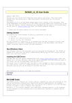
Figure 1 BV-COM
The main screen
to the internet
will be a local
Tools
at the bottom of the tool is the help file for BV-Tools. If connected
this will come from there if there is no internet connection then it
file.
Starting with BV4629
It is assumed that BV-Tools is up and running and the BV4629 is plugged into the USB
and the COM port for this is known.
Step 1
Connect the BV4629 to the USB, make sure that the correct com port is selected and
This will then turn green to show that a connection
press the red, connect icon
has been made. In the devices selector, just under the about box, select 4629
This will check the BV4629 to see if it is connected and enable various tabs. The
first info tab should be shown that gives some explanation on how to use the BV4629.
The status box to the right hand side of the blue com window will show extra details
of what’s going on. It is NORMAL to receive red error messages in this window. This
is because all of the information is shown. The idea that this is a tool so that the
device can be used in other applications, it is not an end device in itself. The
messages may be useful for diagnosis and information.
Step 2
The device is now ready and anything typed into the blue COM window will appear on
the display. A look at the data sheet will reveal that to clear the screen esc[2J to
enter this press the escape key followed by 2J and the screen will clear. NOTE that
case is important so esc[2j will be wrong and this will cause the device to beep.
Commands
Anything types into the COM terminal, which equates with anything going out of the
COM port, will appear on the screen with one exception and that is the byte value 27
(0x1b). This goes to the COM port when the escape key is pressed. The display will
accept this value as the beginning of a command. The data sheet list all of the
commands in the command table so to draw a line from co-ordinates 10,10 to 50,50 the
command is esc{10 10 50 50L and so forth.
The command will react immediately, in the above case as soon as the ‘L’ is received.
In some commands spaces are also important and so if a command appears not to work
then re-read the description of the command in the data sheet.
Working With Pictures
The device will display any bitmap image provided that it is in the correct format.
The BV Tool will take a BMP file, convert it to the correct format and then send it
to the device. The BMP file MUST have a colour depth of 24 bits. A paint tool will be
able to convert any format into this format which is sometimes called 32K or 64K
colours.
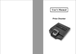
As a demonstration select the BMP tab in BV-Tools. There is a picture called
‘Butterfly.bmp’ in the BV-Tools directory. If it is not in the picture panel as shown
in Figure 2 then use the browse button to load it. Use the button pointing to the
left to send it to the display at the current cursor position. Use the ‘picture
Position’ boxes to send it to the display at differing co-ordinates; 0,0 for example.
Information:
It is important to realise that the BMP file is NOT being sent to the display. The
BV-Tool will convert this file into another format before sending it.
Figure 2 BMP Tab
For a ‘REAL’ application you may want to convert the files into a suitable format for
downloading via another application. To do this use the ‘BMPConvert.exe’ toll that is
in the resource pack. This will convert BMP files to BMC files, the BMC file can be
downloaded to the display by first giving the command esc{b and then sending the file
through the serial interface.
Bit map files can also be stored on the Flash so that they can be presented on the
display without the need for downloading first. This is ideal for static data such as
buttons. There is more information about this in the section on Flash.
Fonts
There are several built in fonts that can be accessed with esc(<number> where the
number is the built in font number. Fonts can also be designed by the user and
downloaded. A font file has an extension of BFF and just to show how this works use
the browse button in the BFF Font section of the BMP tab and select ‘Baskerville Old
Face.bff’. This can be found in the resources zip file. When selected, press the ‘<<
Send to’ button and then type something in at the Blue COM screen, you should see
that the text on the device is a different font.
Creating Fonts
This is done with an excellent piece of free software from ‘Codehead’
(http://www.codehead.co.uk/cbfg/) The current version at the time of writing is in
the resources zip file. The file is called CBFG.exe, just double click on it to get
it working.
The program works by creating a bitmap of the selected font, this is then saved as a
BFF file and the BFF file is converted by the BV-Tool for the display. Most of the
fonts are proportional (differing widths) and the BV4629 will handle this.
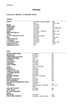
To see how this works, launch CBFG and choose the Georgia font:
Figure 3 CBFG Program from 'Codehead'
Choose the settings as shown in Figure 3. Don’t forget that this display is small
relative to a PC screen and so the modest cell height and width above are still
medium sized.
Save the file using file>save and choose the 24 bit option:
This will save the BFF file which can be imported into the BV-Tool and subsequently
sent to the device.
Don’t expect all the features to work 100%, the colour for example must be black.
This of course can be changed at the device level by selecting a different foreground
colour.
For applications other than using the BV-Tool the BFF file is not suitable for
sending directly to the display. In this case a ‘BF’ (Binary format) file is
required. This can be created using the BV-Tool by selecting the appropriate tick
box, in this case ‘Create Binary file’ and using the Create File button.
This file can then be loaded down the serial port using the esc(0 (zero) command.
Flash Memory
For devices fitted with less than 16Mb, blocks outside the range will show as red
(not blank). The following text assumes that 16Mb is fitted.
The display has a 16Mb (2M Byte) flash memory for storing mainly display data. The
memory can hold system data, font data, picture data and macro data. It is organised
as 500 (0 to 499) blocks of 4kB each.
The blocks must be erased before being written to, there are no checks so it is up to
the user to make sure that the blocks being written to are blank. If the blocks are
not blank then the data will be corrupt and unpredictable results will be achieved.
Writing data to the flash is carried out using the appropriate command for the data
being stored. The data is sent to the serial port after the command has been issued.
To assist with the use of flash memory the BV-Tool provides a display:
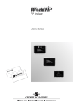
Figure 4 Flash Memory Map
and the panel should ‘colour in’, this can also be
Click the refresh button
displayed on the actual device by using esc[f command, try it and it should be
exactly the same as the one on the PC screen – which may not be the same as shown in
Figure 4.
RED: This means that the block is not blank
GREEN : This means that the block is blank
BLUE: Is the START of a bitmap
YELLOW: Is the start of macro
FUCHA: Is the start of a Font
Each rectangle represents one 4k block of memory, there are 10 across and 50 down
making a total of 500 blocks numbered from 0. In Figure 4 block 0 is red, this is the
system block. Block 10 is blue so this must be the start of a picture, as must blocks
12 and 14. Some indication is given to the size of the pictures, the first two occupy
two blocks and the last one occupies 17 blocks including the start.
This map is obtained by BV-Tool using the esc{<bl>q command that returns a value
indicating what is in the block. The command has to be sent 500 times to obtain a
full picture.
System Data
Block 0 contains system data such as the Baud Rate, screen calibration and the like.
It is normally written to and read by the system using system commands, for example
esc[?27D (look it up). The user can still delete this block, the system will then
revert to some default values.
Picture Data
Picture data takes up the most space. A full screen is 240 x 320 x 3 which is 230kB
or 56 blocks. For most applications a full screen will not be required, several
buttons could be stored for example that change as the application progresses. Each
button can be stored in its own block. The retrieval and display of a bitmap is much
quicker when used from Flash as it does not have to be serially loaded. As an example
load the butterfly picture to block 60 (7 lines down). Do this by picking on block 60
with the mouse. The top of the map will tell you that block 60 has been selected.
With the butterfly picture loaded, click the Send To >> button pointing to the flash.
This is obviously the top Send To >> button as this is in the BMP group. The one at
the bottom is for the fonts.
After a few seconds, refresh
the map again and you will see there is a lot more
red. Clear the device screen first by typing esc[2J in the blue COM screen, click on
block 60 again, this will now be blue and click the long ‘<< Send Selected <<’
button. The picture will appear on the screen.
There are a couple of things that may not be clear about what is happening when using
this demonstration. The first is that the picture data is not coming from the PC but
is now internal to the device and so that picture can be displayed independently. The
second thing to appreciate is that the command for sending data from the Flash to the
screen is the same command esc{<bl>r for all types of data. There is a marker placed
on the data when it is saved and so the device knows how to display it.
Font Data
In exactly the same why as pictures, fonts can also be stored to flash using the
‘Send To >>’ button but in the Font group. In this way many fonts can be stored and
recalled with esc{<bl>r when required. Simply store the fonts into particular blocks
and recall when needed by specifying that block.
Macro Data
This can be used to automate a process and is simply a record of a set of commands.
Of course these commands can call pictures and fonts. The macro can also be made to
run at start up so a customisable start up or splash screen is possible. In a real
application this could come on whilst the processor it is attached to boots up for
example. There are some limitations when using a macro and these are repeated here
form the data sheet.
1. The maximum size of a macro is 100 bytes. This is not a particular restriction
as a macro can call text and other images from Flash.
2. When saving a macro to run at start up, the baud rate also becomes fixed to
whatever it is currently set at.
3. Turning off the macro will not automatically turn off the fixed Baud rate.
Sign on example
To get the hang of using this feature an example follows that will display a sign on
screen and then some text in a different font. The butterfly picture is too big as we
need to put some text underneath, so store to flash, a picture called
‘front_screen.bmp’ at block 130. The macro sign on will be the following commands:
#27[2J#27{130r#27(5New Sign On Screen
In the above string #27 represents the escape key. It is advisable to type this in at
the COM screen first to make sure it works (see the strings section later for an easy
way to do this).
To write the macro add the following:
#27{180M#27[2J#27{130r#27(5New Sign On Screen#27#27
The bits shown in red at the front and back. The first bit is the command to begin a
macro and the 180 is the block number that it will be written to. The last two
escapes are how a macro is terminated. When this string is entered there will be a
macro block at 180.
This can be tested using the #27{180r command that will run the macro.
This is how the panel now looks after refresh, it can be seen that there is now a
macro block at 180.
Touch Screen
The BV4629 is equipped with a touch screen and there are various commands that
manipulate this. The screen must be calibrated first. The calibration settings are
stored in the system block (0) and at start up the display checks to see if it has
been calibrated, if not it will prompt the user to re-calibrate which is a very
simple process.
Calibration
The command for calibration is #27[c. After issuing this command it is a ‘simple’
matter of selecting 3 dots. The ‘simple’ is in quotes because it needs a steady hand
and you must not touch the screen elsewhere with your hand. It takes a bit of
practice. The calibration is only saved temporarily. To save it permanently to block
0 (the system block) then use the #27?27D command, note that this will also save the
current settings and Baud rate.
Interrupt
When the screen is touched it will hold pin 2 of the serial interface connector low,
it also sets an internal flag and the Ring indicator attached to the USB. To see how
the software flag works, touch the screen and use the last touch command #27[l, it
will show x,y,L where L will be 1. If you send the command again without touching the
screen then the same co-ordinates will be returned but this time L will be 0,
indicating that you have already, read those co-ordinates. This is the software
interrupt flag.
The same applies for hardware, when the co-ordinates are read, the interrupt pin
returns high, if you have a meter you can verify this. BV-Tools makes use of the Ring
Indicator (RI in RS232 Speak). It is in-fact designed to wake up a modem when the
telephone is ringing. Check the box to the lower left of the BMP tab page:
Now touch the screen and you will see that the co-ordinates change. What BV-Tools is
doing is detecting the RI and then issuing the last touch command to retrieve the coordinates. This happens quite quickly and so there may be one or two errors that show
up in the status screen, this is normal.
This feature is very useful for obtaining the co-ordinates of buttons for example and
then using Area hit. As an example of how this may work, we can load up some buttons
and one of them will load another image.
1. Load up the ‘clock.bmp file from the resources zip and save it to block 190.
2. Now load up ‘front_screen.bmp’ from block 130 or if you have deleted it from
the resources zip. (Use #27[2J to clear the screen first).
3. Find out the co-ordinates of the clock button. Pick the top left and bottom
right, I get 69,158 and 112,213. Don’t forget that this may be different on
your display.
4. Run this command #27{69,158,112,216H#27[2J#27{190r
This will wait until the screen has been touched in the correct place, as specified
by the co-ordinates before returning, it will then clear the screen and display the
larger clock. The following command will do all of the above in one go.
#27[2J#27{130r#27{69,158,109,206H#27[2J#27{190r
This is as far as you can go using scripts and without programming. In an application
it is better to use the lower case ‘h’ version of the command as that command will
return either 0 or 1 depending on where the screen was touched. The host program can
then decide what to do.
When the command has been run the soft interrupt flag is set and this must be cleared
by reading the last touch (#27[l).
Strings
This is a useful utility which is in the process of being written and so there are
some known bugs and issues.
To use this facility, pick on the ‘strings.scr’ file that is shown far right, this
will populate the top index area. Click on one of the letters (T in the picture at
Figure 5) and then on one of the words down the left hand side. You can edit the text
in the main box, save it and send it to the COM port using the send button.
It will work most of the time and saves a lot of re-typing.
When using this remember that ALL characters are important and WILL be sent to the
display including Line feed, so sending two ‘beeps’ to the diplay like this:
#27[900;2b
#27[850;2b
Will cause the display to beep twice but will also put the cursor down one. If no
side effects are wanted the this would be the command to use:
#27[900;2b#27[850;2b
Figure 5 Strings
Firmware Update
Should the firmware require upgrading then this is possible using BV-Tools. The
current firmware can be found with this esc[?30a command and will be a decimal
number.
New firmware if available can be found in the resources zip file or on the ByVac
website, it will be a file with a .bin extension. To update the firmware simply use
the Update menu that will show this dialog:
Select the file and press upload, it takes just a few seconds. The firmware update
does not update the flash and so any system settings will remain.
Factory Reset
Factory reset will simply delete the contents of the Flash system block 0. It could
be possible that an impossible macro has been inadvertently programmed into this and
is causing the device to not start up. In this instance the system block can be
erased from a hardware ‘instruction’
1. At the top of the display is a row of 10 holes, at one side there is a square
one, this is pin 1. It is also marked as pin 1 on the PCB.
2. Disconnect the display and use a piece of wire to short out pins 3 & 4, just
hold the wire in place by hand.
3. Connect the display and then remove the wire.
The display will now have a blank system block 0. You will see the calibration
screen, calibrate the touch screen and the display is now back to ‘normal’
Programming Notes
There are some important aspects to consider when using this device concerning the
communication flow. The device has a serial buffer and so will accept up to about 80
bytes before becoming full. The buffer will become full when the incoming data is
coming faster then the device can service it. When the buffer becomes full it pulls
the RTS line low. This state should be monitored by the host and the host should stop
sending until the RTS lines goes high again.
Receiving data from the touch screen is another consideration. A command is sent to
the device and then the device will respond with information. The problem here is
that the data is of variable length and so it is important to wait for the
terminating character before reading the device. An example may better explain:
Host: sends out #27[l (last touch command)
Device: after a finite time responds with “110,65#13” In bytes this would be
#49#49#48#44#54#53#13
It is important therefore not to read the device too early otherwise some data may be
missed. The technique is to read in bytes from the device until #13 is received. This
data can then be parsed to extract the co-ordinates. It may also be wise to
incorporate a time out whilst waiting for the #13 in case something goes wrong.
An alternative to waiting for the #13 is to specify a particular character using the
#27[<char>E command. Not all commands will respond with #13, using the #27[<char>E
command will ensure that just about every command will respond with whatever is
specified, this ensures that command like clear the screen that take a relatively
long time will have completed before sending the next command.
In summary:
Start up:
send #13 (to establish Baud rate)
send #27[#42E (to set the ACK at *)
Send:
while RTS is high send data
Receive:
while byte <> ‘*’ get byte, store byte to string
(return string when byte = ‘*’)
Tips & Notes
Device Dropdown & Reset
When selecting a device it uses the <device>.ini file to set up BV-Tools to what the
device expects, it may set up ACK conditions CTS etc. So for correct operation, the
conditions are mostly required.
If the device is reset using the reset icon
then the conditions are lost and
some features of BV-Tools will not work correctly. This will probably be indicated by
lots of red text in the status panel. To get back the status quo select ‘none’ then
the device again, this will re-read the .ini file and set up BV-Tools correctly.
Internet
BV-Tools checks to see if there is an internet connection, if there is then the info
pages are displayed from a directory off of the www.byvac.com site. In this way any
updates or information are always available. If however the internet is not available
then a local copy of the .htm files are used. If this is the case then it is
advisable to check for updates. BV-Tool updates can be found at the above website in
the section that deals with this device.
Secret Demo
To activate this do the following:
1) load the picture paintButton.bmp into block 10
2) load the picture stylophone.bmp into block 12
3) load the picture stylophoneButton.bmp into block 14
4) reset and press enter.
5) pick the screen icon, bottom far left of the touch screen to start and the home
icon to finish.