1
E.B.P.L. U SER G UIDE AND L ANGUAGE
R EFERENCE
J ONATHAN M ACEY
21st August 2003
Contents
1 Introduction
1.1 ebpl structure . . . . . . . . . .
1.2 BrainCompiler . . . . . . . . .
1.3 ebpl program. . . . . . . . . . .
1.4 Getting started . . . . . . . . . .
1.4.1 Running the simulation.
.
.
.
.
.
.
.
.
.
.
.
.
.
.
.
.
.
.
.
.
.
.
.
.
.
.
.
.
.
.
.
.
.
.
.
.
.
.
.
.
.
.
.
.
.
.
.
.
.
.
.
.
.
.
.
.
.
.
.
.
.
.
.
.
.
.
.
.
.
.
.
.
.
.
.
.
.
.
.
.
.
.
.
.
.
.
.
.
.
.
.
.
.
.
.
.
.
.
.
.
.
.
.
.
.
.
.
.
.
.
.
.
.
.
.
.
.
.
.
.
.
.
.
.
.
.
.
.
.
.
.
.
.
.
.
.
.
.
.
.
.
.
.
.
.
.
.
.
.
.
.
.
.
.
.
1
1
1
1
2
4
2 ebpl Language
2.1 Agent Characteristics . . . . . .
2.2 Agent Brain . . . . . . . . . . .
2.2.1 Brain Stacks . . . . . .
2.2.2 Global Variables . . . .
2.2.3 Variables . . . . . . . .
2.2.4 Functions . . . . . . . .
2.2.5 Call Lists . . . . . . . .
2.3 EBPL language structure . . . .
2.3.1 Stack Operations . . . .
2.3.2 Variable Operations . . .
2.3.3 Variable Opcodes . . . .
2.3.4 Collisions . . . . . . . .
2.3.5 Environment Collisions .
2.3.6 Structure Opcodes . . .
2.4 Drawing . . . . . . . . . . . . .
2.4.1 MiniGL Opcodes . . . .
2.4.2 Affine Transforms . . .
2.4.3 Drawing Primitives . . .
2.4.4 Line Drawing . . . . . .
2.4.5 MiniGL Example . . . .
2.4.6 AgentRender . . . . . .
.
.
.
.
.
.
.
.
.
.
.
.
.
.
.
.
.
.
.
.
.
.
.
.
.
.
.
.
.
.
.
.
.
.
.
.
.
.
.
.
.
.
.
.
.
.
.
.
.
.
.
.
.
.
.
.
.
.
.
.
.
.
.
.
.
.
.
.
.
.
.
.
.
.
.
.
.
.
.
.
.
.
.
.
.
.
.
.
.
.
.
.
.
.
.
.
.
.
.
.
.
.
.
.
.
.
.
.
.
.
.
.
.
.
.
.
.
.
.
.
.
.
.
.
.
.
.
.
.
.
.
.
.
.
.
.
.
.
.
.
.
.
.
.
.
.
.
.
.
.
.
.
.
.
.
.
.
.
.
.
.
.
.
.
.
.
.
.
.
.
.
.
.
.
.
.
.
.
.
.
.
.
.
.
.
.
.
.
.
.
.
.
.
.
.
.
.
.
.
.
.
.
.
.
.
.
.
.
.
.
.
.
.
.
.
.
.
.
.
.
.
.
.
.
.
.
.
.
.
.
.
.
.
.
.
.
.
.
.
.
.
.
.
.
.
.
.
.
.
.
.
.
.
.
.
.
.
.
.
.
.
.
.
.
.
.
.
.
.
.
.
.
.
.
.
.
.
.
.
.
.
.
.
.
.
.
.
.
.
.
.
.
.
.
.
.
.
.
.
.
.
.
.
.
.
.
.
.
.
.
.
.
.
.
.
.
.
.
.
.
.
.
.
.
.
.
.
.
.
.
.
.
.
.
.
.
.
.
.
.
.
.
.
.
.
.
.
.
.
.
.
.
.
.
.
.
.
.
.
.
.
.
.
.
.
.
.
.
.
.
.
.
.
.
.
.
.
.
.
.
.
.
.
.
.
.
.
.
.
.
.
.
.
.
.
.
.
.
.
.
.
.
.
.
.
.
.
.
.
.
.
.
.
.
.
.
.
.
.
.
.
.
.
.
.
.
.
.
.
.
.
.
.
.
.
.
.
.
.
.
.
.
.
.
.
.
.
.
.
.
.
.
.
.
.
.
.
.
.
.
.
.
.
.
.
.
.
.
.
.
.
.
.
.
.
.
.
.
.
.
.
.
.
.
.
.
.
.
.
.
.
.
.
.
.
.
.
.
.
.
.
.
.
.
.
.
.
.
.
.
.
.
.
.
.
.
.
.
.
.
.
.
.
.
.
.
.
.
.
.
.
.
.
.
.
.
.
.
.
.
.
.
.
.
.
.
.
.
.
.
.
.
.
.
.
.
.
.
.
.
.
.
.
.
.
.
.
.
.
.
.
.
.
.
.
.
.
.
.
.
.
.
.
.
.
.
.
.
.
.
.
.
.
.
.
.
.
.
.
.
.
.
.
.
.
.
.
.
.
.
.
.
.
.
.
.
.
.
.
.
.
.
.
.
.
.
.
.
.
.
.
.
.
.
.
.
.
.
.
.
.
.
.
.
.
.
.
.
.
.
.
5
5
5
6
7
7
7
8
8
8
11
11
12
13
14
15
15
15
16
17
19
20
3 Programmable Particles
3.1 Simple Particles . . . . . .
3.2 Cone Emit Particles . . . .
3.2.1 Wind vector . . . .
3.3 Projectile Motion Particles
.
.
.
.
.
.
.
.
.
.
.
.
.
.
.
.
.
.
.
.
.
.
.
.
.
.
.
.
.
.
.
.
.
.
.
.
.
.
.
.
.
.
.
.
.
.
.
.
.
.
.
.
.
.
.
.
.
.
.
.
.
.
.
.
.
.
.
.
.
.
.
.
.
.
.
.
.
.
.
.
.
.
.
.
.
.
.
.
.
.
.
.
.
.
.
.
.
.
.
.
.
.
.
.
.
.
.
.
.
.
.
.
.
.
.
.
.
.
.
.
.
.
.
.
24
24
26
27
29
4 Flocking
4.1 A simple Flock in ebpl . . . . . . . . . . . . . . . . . . . . . . . . . . . . . . . . . . . .
4.2 Advanced Flocking . . . . . . . . . . . . . . . . . . . . . . . . . . . . . . . . . . . . . .
4.3 Avoiding Objects . . . . . . . . . . . . . . . . . . . . . . . . . . . . . . . . . . . . . . .
32
33
38
47
5 Agent Render
53
.
.
.
.
.
.
.
.
.
.
.
.
i
CONTENTS
5.1
5.2
5.3
5.4
Agent Resource File (ARF) . . . .
Using the AgentRender . . . . . .
Using arf to set Agent target points
Agents with Collisions . . . . . .
ii
.
.
.
.
.
.
.
.
.
.
.
.
.
.
.
.
.
.
.
.
.
.
.
.
.
.
.
.
.
.
.
.
.
.
.
.
.
.
.
.
.
.
.
.
.
.
.
.
53
54
57
60
6 Terrain Interaction
6.0.1 Loading Terrain . . . . . . . . . . . . . . . . . . . . . . . . . . . . . . . . . . . .
6.1 Complex Agent Interactions using CallLists . . . . . . . . . . . . . . . . . . . . . . . . .
63
64
67
7 Language Reference
7.1 Variable syntax . . . . . . . . . . . . . . . . . . . .
7.1.1 Float . . . . . . . . . . . . . . . . . . . . .
7.1.2 Point . . . . . . . . . . . . . . . . . . . . .
7.1.3 Vector . . . . . . . . . . . . . . . . . . . . .
7.1.4 Bool . . . . . . . . . . . . . . . . . . . . . .
7.1.5 Fuzzy . . . . . . . . . . . . . . . . . . . . .
7.2 Agent Global Variables . . . . . . . . . . . . . . . .
7.2.1 SetGlobalPos GetGlobalPos . . . . . . . . .
7.2.2 SetGlobalDir GetGlobalDir . . . . . . . . .
7.2.3 SetGlobalCentroid GetGlobalCentroid . . . .
7.2.4 SetGlobalCollideFlag GetGlobalCollideFlag
7.2.5 SetGPYlevel . . . . . . . . . . . . . . . . .
7.2.6 PushGPYLevel . . . . . . . . . . . . . . . .
7.3 Collisions . . . . . . . . . . . . . . . . . . . . . . .
7.3.1 Environment Collisions . . . . . . . . . . . .
7.4 Functions . . . . . . . . . . . . . . . . . . . . . . .
7.5 Call Lists . . . . . . . . . . . . . . . . . . . . . . .
7.6 Bins and Other Agent Access . . . . . . . . . . . . .
7.7 MiniGL Opcodes . . . . . . . . . . . . . . . . . . .
7.7.1 RotateX . . . . . . . . . . . . . . . . . . . .
7.7.2 RotateY . . . . . . . . . . . . . . . . . . . .
7.7.3 RotateZ . . . . . . . . . . . . . . . . . . . .
7.7.4 PushMatrix . . . . . . . . . . . . . . . . . .
7.7.5 PopMatrix . . . . . . . . . . . . . . . . . .
7.7.6 Translate . . . . . . . . . . . . . . . . . . .
7.7.7 Polygon . . . . . . . . . . . . . . . . . . . .
7.7.8 Quad . . . . . . . . . . . . . . . . . . . . .
7.7.9 Point . . . . . . . . . . . . . . . . . . . . .
7.7.10 LineLoop . . . . . . . . . . . . . . . . . . .
7.7.11 glEnd . . . . . . . . . . . . . . . . . . . . .
7.7.12 Vertex . . . . . . . . . . . . . . . . . . . . .
7.7.13 Vertexf . . . . . . . . . . . . . . . . . . . .
7.7.14 PointSize . . . . . . . . . . . . . . . . . . .
7.7.15 LineSize . . . . . . . . . . . . . . . . . . .
7.7.16 Sphere . . . . . . . . . . . . . . . . . . . .
7.7.17 Cylinder . . . . . . . . . . . . . . . . . . .
7.7.18 Colour . . . . . . . . . . . . . . . . . . . .
7.7.19 Lighting . . . . . . . . . . . . . . . . . . . .
7.8 AgentRender . . . . . . . . . . . . . . . . . . . . .
7.9 Float Stack Opcodes . . . . . . . . . . . . . . . . .
7.9.1 Fpush . . . . . . . . . . . . . . . . . . . . .
7.9.2 Fpushd . . . . . . . . . . . . . . . . . . . .
7.10 Fpop . . . . . . . . . . . . . . . . . . . . . . . . . .
7.10.1 Fadd . . . . . . . . . . . . . . . . . . . . . .
72
72
72
72
72
72
73
73
73
73
73
74
74
74
74
75
75
76
76
76
76
77
77
77
77
77
77
77
77
78
78
78
78
78
78
78
79
79
79
79
80
80
81
81
81
.
.
.
.
.
.
.
.
.
.
.
.
.
.
.
.
.
.
.
.
.
.
.
.
.
.
.
.
.
.
.
.
.
.
.
.
.
.
.
.
.
.
.
.
.
.
.
.
.
.
.
.
.
.
.
.
.
.
.
.
.
.
.
.
.
.
.
.
.
.
.
.
.
.
.
.
.
.
.
.
.
.
.
.
.
.
.
.
.
.
.
.
.
.
.
.
.
.
.
.
.
.
.
.
.
.
.
.
.
.
.
.
.
.
.
.
.
.
.
.
.
.
.
.
.
.
.
.
.
.
.
.
.
.
.
.
.
.
.
.
.
.
.
.
.
.
.
.
.
.
.
.
.
.
.
.
.
.
.
.
.
.
.
.
.
.
.
.
.
.
.
.
.
.
.
.
.
.
.
.
.
.
.
.
.
.
.
.
.
.
.
.
.
.
.
.
.
.
.
.
.
.
.
.
.
.
.
.
.
.
.
.
.
.
.
.
.
.
.
.
.
.
.
.
.
.
.
.
.
.
.
.
.
.
.
.
.
.
.
.
.
.
.
.
.
.
.
.
.
.
.
.
.
.
.
.
.
.
.
.
.
.
.
.
.
.
.
.
.
.
.
.
.
.
.
.
.
.
.
.
.
.
.
.
.
.
.
.
.
.
.
.
.
.
.
.
.
.
.
.
.
.
.
.
.
.
.
.
.
.
.
.
.
.
.
.
.
.
.
.
.
.
.
.
.
.
.
.
.
.
.
.
.
.
.
.
.
.
.
.
.
.
.
.
.
.
.
.
.
.
.
.
.
.
.
.
.
.
.
.
.
.
.
.
.
.
.
.
.
.
.
.
.
.
.
.
.
.
.
.
.
.
.
.
.
.
.
.
.
.
.
.
.
.
.
.
.
.
.
.
.
.
.
.
.
.
.
.
.
.
.
.
.
.
.
.
.
.
.
.
.
.
.
.
.
.
.
.
.
.
.
.
.
.
.
.
.
.
.
.
.
.
.
.
.
.
.
.
.
.
.
.
.
.
.
.
.
.
.
.
.
.
.
.
.
.
.
.
.
.
.
.
.
.
.
.
.
.
.
.
.
.
.
.
.
.
.
.
.
.
.
.
.
.
.
.
.
.
.
.
.
.
.
.
.
.
.
.
.
.
.
.
.
.
.
.
.
.
.
.
.
.
.
.
.
.
.
.
.
.
.
.
.
.
.
.
.
.
.
.
.
.
.
.
.
.
.
.
.
.
.
.
.
.
.
.
.
.
.
.
.
.
.
.
.
.
.
.
.
.
.
.
.
.
.
.
.
.
.
.
.
.
.
.
.
.
.
.
.
.
.
.
.
.
.
.
.
.
.
.
.
.
.
.
.
.
.
.
.
.
.
.
.
.
.
.
.
.
.
.
.
.
.
.
.
.
.
.
.
.
.
.
.
.
.
.
.
.
.
.
.
.
.
.
.
.
.
.
.
.
.
.
.
.
.
.
.
.
.
.
.
.
.
.
.
.
.
.
.
.
.
.
.
.
.
.
.
.
.
.
.
.
.
.
.
.
.
.
.
.
.
.
.
.
.
.
.
.
.
.
.
.
.
.
.
.
.
.
.
.
.
.
.
.
.
.
.
.
.
.
.
.
.
.
.
.
.
.
.
.
.
.
.
.
.
.
.
.
.
.
.
.
.
.
.
.
.
.
.
.
.
.
.
.
.
.
.
.
.
.
.
.
.
.
.
.
.
.
.
.
.
.
.
.
.
.
.
.
.
.
.
.
.
.
.
.
.
.
.
.
.
.
.
.
.
.
.
.
.
.
.
.
.
.
.
.
.
.
.
.
.
.
.
.
.
.
.
.
.
.
.
.
.
.
.
.
.
.
.
.
.
.
.
.
.
.
.
.
.
.
.
.
.
.
.
.
.
.
.
.
.
.
.
.
.
.
.
.
.
.
.
.
.
.
.
.
.
.
.
.
.
.
.
.
.
.
.
.
.
.
.
.
.
.
.
.
.
.
.
.
.
.
.
.
.
.
.
.
.
.
.
.
.
.
.
.
.
.
.
.
.
.
.
.
.
.
.
.
.
.
.
.
.
.
.
.
.
.
.
.
.
.
.
.
.
.
.
.
.
.
.
.
.
.
.
.
.
.
.
.
.
.
CONTENTS
.
.
.
.
.
.
.
.
.
.
.
.
.
.
.
.
.
.
.
.
.
.
.
.
.
.
.
.
.
.
.
.
.
.
.
.
.
.
.
.
.
.
.
.
.
.
.
.
.
.
.
.
.
.
.
.
.
.
.
.
.
.
.
.
.
.
.
.
.
.
.
.
.
.
.
.
.
.
.
.
.
.
.
.
.
.
.
.
.
.
.
.
.
.
.
.
.
.
.
.
.
.
.
.
.
.
.
.
.
.
.
.
.
.
.
.
.
.
.
.
.
.
.
.
.
.
.
.
.
.
.
.
.
.
.
.
.
.
.
.
.
.
.
.
.
.
.
.
.
.
.
.
.
.
.
.
.
.
.
.
.
.
.
.
.
.
.
.
.
.
.
.
.
.
.
.
.
.
.
.
.
.
.
.
.
.
.
.
.
.
.
.
.
.
.
.
.
.
.
.
.
.
.
.
.
.
.
.
.
.
.
.
.
.
.
.
.
.
.
.
.
.
.
.
.
.
.
.
.
.
.
.
.
.
.
.
.
.
.
.
.
.
.
.
.
.
.
.
.
.
.
.
.
.
.
.
.
.
.
.
.
.
.
.
.
.
.
.
.
.
.
.
.
.
.
.
.
.
.
.
.
.
.
.
.
.
.
.
.
.
.
.
.
.
.
.
.
.
.
.
.
.
.
.
.
.
.
.
.
.
.
.
.
.
.
.
.
.
.
.
.
.
.
.
.
.
.
.
.
.
.
.
.
.
.
.
.
.
.
.
.
.
.
.
.
.
.
.
.
.
.
.
.
.
.
.
.
.
.
.
.
.
.
.
.
.
.
.
.
.
.
.
.
.
.
.
.
.
.
.
.
.
.
.
.
.
.
.
.
.
.
.
.
.
.
.
.
.
.
.
.
.
.
.
.
.
.
.
.
.
.
.
.
.
.
.
.
.
.
.
.
.
.
.
.
.
.
.
.
.
.
.
.
.
.
.
.
.
.
.
.
.
.
.
.
.
.
.
.
.
.
.
.
.
.
.
.
.
.
.
.
.
.
.
.
.
.
.
.
.
.
.
.
.
.
.
.
.
.
.
.
.
.
.
.
.
.
.
.
.
.
.
.
.
.
.
.
.
.
.
.
.
.
.
.
.
.
.
.
.
.
.
.
.
.
.
.
.
.
.
.
.
.
.
.
.
.
.
.
.
.
.
.
.
.
.
.
.
.
.
.
.
.
.
.
.
.
.
.
.
.
.
.
.
.
.
.
.
.
.
.
.
.
.
.
.
.
.
.
.
.
.
.
.
.
.
.
.
.
.
.
.
.
.
.
.
.
.
.
.
.
.
.
.
.
.
.
.
.
.
.
.
.
.
.
.
.
.
.
.
.
.
.
.
.
.
.
.
.
.
.
.
.
.
.
.
.
.
.
.
.
.
.
.
.
.
.
.
.
.
.
.
.
.
.
.
.
.
.
.
.
.
.
.
.
.
.
.
.
.
.
.
.
.
.
.
.
.
.
.
.
.
.
.
.
.
.
.
.
.
.
.
.
.
.
.
.
.
.
.
.
.
.
.
.
.
.
.
.
.
.
.
.
.
.
.
.
.
.
.
.
.
.
.
.
.
.
.
.
.
.
.
.
.
.
.
.
.
.
.
.
.
.
.
.
.
.
.
.
.
.
.
.
.
.
.
.
.
.
.
.
.
.
.
.
.
.
.
.
.
.
.
.
.
.
.
.
.
.
.
.
.
.
.
.
.
.
.
.
.
.
.
.
.
.
.
.
.
.
.
.
.
.
.
.
.
.
.
.
.
.
.
.
.
.
.
.
.
.
.
.
.
.
.
.
.
.
.
.
.
.
.
.
.
.
.
.
.
.
.
.
.
.
.
.
.
.
.
.
.
.
.
.
.
.
.
.
.
.
.
.
.
.
.
.
.
.
.
.
.
.
.
.
.
.
.
.
.
.
.
.
.
.
.
.
.
.
.
.
.
.
.
.
.
.
.
.
.
.
.
.
.
.
.
.
.
.
.
.
.
.
.
.
.
.
.
.
.
.
.
.
.
.
.
.
.
.
.
.
.
.
.
.
.
.
.
.
.
.
.
.
.
.
.
.
.
.
.
.
.
.
.
.
.
.
.
.
.
.
.
.
.
.
.
.
.
.
.
.
.
.
.
.
.
.
.
.
.
.
.
.
.
.
.
.
.
.
.
.
.
.
.
.
.
.
.
.
.
.
.
.
.
.
.
.
.
.
.
.
.
.
.
.
.
.
.
.
.
.
.
.
.
.
.
.
.
.
.
.
.
.
.
.
.
.
.
.
.
.
.
.
.
.
.
.
.
.
.
.
.
.
.
.
.
.
.
.
.
.
.
.
.
.
.
.
.
.
.
.
.
.
.
.
.
.
.
.
.
.
.
.
.
.
.
.
.
.
.
.
.
.
.
.
.
.
.
.
.
.
.
.
.
.
.
.
.
.
.
.
.
.
.
.
.
.
.
.
.
.
.
81
81
81
81
81
81
82
82
82
82
82
82
82
82
82
83
83
83
83
83
84
84
84
84
84
84
85
85
85
85
85
85
86
86
86
86
87
8 .fl Script reference
8.0.1 Keys . . . . . . . . . . . .
8.1 Flocking System Script File Format
8.1.1 Environment Parameters . .
8.1.2 Emitters . . . . . . . . . . .
.
.
.
.
.
.
.
.
.
.
.
.
.
.
.
.
.
.
.
.
.
.
.
.
.
.
.
.
.
.
.
.
.
.
.
.
.
.
.
.
.
.
.
.
.
.
.
.
.
.
.
.
.
.
.
.
.
.
.
.
.
.
.
.
.
.
.
.
.
.
.
.
.
.
.
.
.
.
.
.
.
.
.
.
.
.
.
.
.
.
.
.
.
.
.
.
.
.
.
.
.
.
.
.
.
.
.
.
.
.
.
.
.
.
.
.
88
88
89
89
93
7.11
7.12
7.13
7.14
7.10.2 Fsub . . . . .
7.10.3 Fmul . . . . .
7.10.4 Fdiv . . . . . .
7.10.5 Fdup . . . . .
7.10.6 Fsqrt . . . . .
7.10.7 Frad2Deg . . .
7.10.8 Fatan . . . . .
7.10.9 Fsin . . . . . .
7.10.10 Fasin . . . . .
7.10.11 Fcos . . . . . .
7.10.12 Facos . . . . .
7.10.13 Fnegate . . . .
7.10.14 FStackTrace .
Variable Opcodes . . .
7.11.1 Add . . . . . .
7.11.2 Sub . . . . . .
7.11.3 Mul . . . . . .
7.11.4 Div . . . . . .
7.11.5 Set . . . . . .
7.11.6 AddD . . . . .
7.11.7 SubD . . . . .
7.11.8 MulD . . . . .
7.11.9 DivD . . . . .
7.11.10 SetD . . . . .
7.11.11 Length . . . .
7.11.12 Normalize . . .
7.11.13 Dot . . . . . .
7.11.14 Reverse . . . .
7.11.15 Randomize . .
7.11.16 RandomizePos
Structure Opcodes . . .
7.12.1 Call . . . . . .
7.12.2 Function . . .
7.12.3 If . . . . . . .
7.12.4 Ifelse . . . . .
Debug . . . . . . . . .
Noise Function . . . .
iii
Bibliography
.
.
.
.
.
.
.
.
.
.
.
.
.
.
.
.
.
.
.
.
.
.
.
.
.
.
.
.
.
.
.
.
.
.
.
.
.
.
.
.
.
.
.
.
.
.
.
.
.
.
.
.
.
.
.
.
.
.
.
.
.
.
.
.
.
.
.
.
.
.
.
.
.
.
.
.
.
.
.
.
.
.
.
.
.
.
.
.
.
.
.
.
.
.
.
.
.
.
.
.
.
.
.
.
.
.
.
.
.
.
.
.
.
.
.
.
.
.
.
.
.
.
.
.
.
.
.
.
.
.
.
.
.
.
.
.
.
.
.
.
.
.
.
.
.
.
.
.
.
.
.
.
.
.
.
.
.
.
.
.
.
.
.
.
.
.
.
.
.
.
.
.
.
.
.
.
.
.
.
.
.
.
.
.
.
.
.
.
.
.
.
.
.
.
.
.
.
.
.
.
.
.
.
.
.
.
.
.
.
.
.
.
.
.
.
.
.
.
.
.
.
.
98
List of Tables
2.1
EBPL variable types . . . . . . . . . . . . . . . . . . . . . . . . . . . . . . . . . . . . .
7
2.2
EBPL variable types . . . . . . . . . . . . . . . . . . . . . . . . . . . . . . . . . . . . .
7
2.3
Stack Operation Prefix . . . . . . . . . . . . . . . . . . . . . . . . . . . . . . . . . . . .
8
2.4
Line Drawing styles[MW99] . . . . . . . . . . . . . . . . . . . . . . . . . . . . . . . . .
18
2.5
AgentRender Opcodes . . . . . . . . . . . . . . . . . . . . . . . . . . . . . . . . . . . .
22
2.6
Material Types . . . . . . . . . . . . . . . . . . . . . . . . . . . . . . . . . . . . . . . .
23
4.1
ebpl Noise functions . . . . . . . . . . . . . . . . . . . . . . . . . . . . . . . . . . . . .
42
7.1
EBPL variable types . . . . . . . . . . . . . . . . . . . . . . . . . . . . . . . . . . . . .
75
7.2
AgentRender Opcodes . . . . . . . . . . . . . . . . . . . . . . . . . . . . . . . . . . . .
80
7.3
Material Types . . . . . . . . . . . . . . . . . . . . . . . . . . . . . . . . . . . . . . . .
80
7.4
ebpl Noise functions . . . . . . . . . . . . . . . . . . . . . . . . . . . . . . . . . . . . .
87
iv
List of Figures
1.1
EBPL environment flow chart . . . . . . . . . . . . . . . . . . . . . . . . . . . . . . . .
2
1.2
Getting Started 50 Random Spheres . . . . . . . . . . . . . . . . . . . . . . . . . . . . .
3
2.1
Agent Class Diagram. . . . . . . . . . . . . . . . . . . . . . . . . . . . . . . . . . . . . .
5
2.2
Agent Brain Structure . . . . . . . . . . . . . . . . . . . . . . . . . . . . . . . . . . . . .
6
2.3
VarObj Class diagram . . . . . . . . . . . . . . . . . . . . . . . . . . . . . . . . . . . . .
7
2.4
Agents avoiding an EnvObj . . . . . . . . . . . . . . . . . . . . . . . . . . . . . . . . . .
13
2.5
MiniGL Line Drawing types . . . . . . . . . . . . . . . . . . . . . . . . . . . . . . . . .
18
2.6
Mini GL drawing . . . . . . . . . . . . . . . . . . . . . . . . . . . . . . . . . . . . . . .
19
2.7
AgentRender module with 6 animations cycles . . . . . . . . . . . . . . . . . . . . . . .
21
2.8
Sample Agent Render model frames . . . . . . . . . . . . . . . . . . . . . . . . . . . . .
21
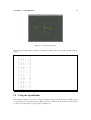
3.1
Simple Particle system Created in EBPL . . . . . . . . . . . . . . . . . . . . . . . . . . .
24
3.2
Cone Emit Particles . . . . . . . . . . . . . . . . . . . . . . . . . . . . . . . . . . . . . .
26
3.3
Cone Emit Particles with wind and different cone angle . . . . . . . . . . . . . . . . . . .
27
3.4
Projectile particles . . . . . . . . . . . . . . . . . . . . . . . . . . . . . . . . . . . . . .
29
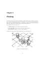
4.1
A simple Flock [Rey87] . . . . . . . . . . . . . . . . . . . . . . . . . . . . . . . . . . . .
32
4.2
Steering Flocking rules [Rey99] . . . . . . . . . . . . . . . . . . . . . . . . . . . . . . .
33
4.3
A simple Flock . . . . . . . . . . . . . . . . . . . . . . . . . . . . . . . . . . . . . . . .
33
4.4
Spherical Geometry[jr01] . . . . . . . . . . . . . . . . . . . . . . . . . . . . . . . . . . .
34
4.5
A flock using complex avoidance and noise functions . . . . . . . . . . . . . . . . . . . .
39
4.6
Agents Avoiding Objects . . . . . . . . . . . . . . . . . . . . . . . . . . . . . . . . . . .
47
5.1
Agent Layout program . . . . . . . . . . . . . . . . . . . . . . . . . . . . . . . . . . . .
54
5.2
AgentRender Agents with different animation cycles . . . . . . . . . . . . . . . . . . . .
55
5.3
Agents moving to position set in arf file . . . . . . . . . . . . . . . . . . . . . . . . . . .
57
5.4
Agents with Collision detection . . . . . . . . . . . . . . . . . . . . . . . . . . . . . . . .
60
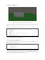
6.1
Agents Interacting with the Terrain . . . . . . . . . . . . . . . . . . . . . . . . . . . . . .
63
6.2
Agents Fighting . . . . . . . . . . . . . . . . . . . . . . . . . . . . . . . . . . . . . . . .
67
6.3
Agents Fighting (close up) . . . . . . . . . . . . . . . . . . . . . . . . . . . . . . . . . .
67
v
List of Algorithms
1
2
3
4
5
6
MiniGL Drawing Example - Reynolds Boids [Rey87]. . .
ConeEmitter modified from[jr01] . . . . . . . . . . . . . .
Projectile Motion modified from [Len01] . . . . . . . . .
Collision avoidance algorithm adapted from [jr01, Len01]
ebpl Code for Agents reflection . . . . . . . . . . . . . . .
Calculating if a point is within a triangle . . . . . . . . . .
vi
.
.
.
.
.
.
.
.
.
.
.
.
.
.
.
.
.
.
.
.
.
.
.
.
.
.
.
.
.
.
.
.
.
.
.
.
.
.
.
.
.
.
.
.
.
.
.
.
.
.
.
.
.
.
.
.
.
.
.
.
.
.
.
.
.
.
.
.
.
.
.
.
.
.
.
.
.
.
.
.
.
.
.
.
.
.
.
.
.
.
.
.
.
.
.
.
.
.
.
.
.
.
20
26
30
40
41
64
Chapter 1
Introduction
ebpl is a development environment for the production of animations using multiple Agents within a userspecified environment, additionally ebpl also allows for the production of particle systems with user programmable particles.
1.1 ebpl structure
The ebpl system is split into two parts, the AgentBrain programming language and the simulation environment. The Agents brain is programed using a simple script language which is compiled to an object
file. This object file is then loaded into the Agent brain within the ebpl system with additional environment
configuration handled by a separate script file.
1.2 BrainCompiler
The Brain compiler is used in the following way
BrainComp [SourceFile].bs [compiledfile].comp
Although the example above uses a .bs and .comp extension the compiler does not require any specific file
names.
If the compilation is successful the compiler will report that everything is OK and save to a .comp
file. If there is an error the compiler will report the problem and what source line number the problem
occurred on.
On occasion the program will hang, this is due to the parser getting stuck, to stop the compiler the ctr + c
keys can be pressed to terminate the program. This error is usually due to a misplaced ; in the source file.
1.3 ebpl program.
The ebpl program loads in an ebpl .fl script and runs the simulation. The .fl script is responsible for
configuring the environment and the placement of the Agents within the environment.
1
CHAPTER 1. INTRODUCTION
2
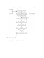
The environment is responsible for containing all the Objects within the scene, as well as calling all of the
Agent’s brain routines as shown in Figure 1.1.
Figure 1.1: EBPL environment flow chart
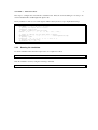
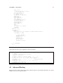
1.4 Getting started
The following section shows a simple ebpl program to place and render 50 random spheres in the environment as shown in Figure 1.2.
CHAPTER 1. INTRODUCTION
3
Figure 1.2: Getting Started 50 Random Spheres
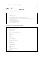
The Agent brain for this simulation is shown in Program 1. When the InitFunction is called on the creation
of the Agents brain the position of each of the Agents is calculated as a random number seeded with the
value 20 10 20 for the x, y and z position.
The Agent is drawn using the Sphere opcode by first setting the colour using the Colour opcode then
translating it to the random position using the Translate command.
Program 1: GettingStarted.bs 50 Random Spheres
// the Agents position
Point Pos=[0,0,0];
InitFunction
// create a random position for the Sphere
Randomize Pos 20 10 20;
End;
DrawFunction
Colour 1.0 1.0 1.0
// save the gl transformation matrix
PushMatrix;
// Translate to the Agents Position
Translate Pos;
// Draw a sphere of radius 2
Sphere 2.0 8 8;
// restore the gl transformation matrix
PopMatrix;
End;
UpdateFunction
// do nothing
End;
CollideFunction
// do nothing
End ;
CHAPTER 1. INTRODUCTION
4
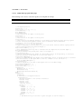
The script to configure the environment is detailed below. First the world bounding box is setup to be
centered at 0,0,0 with a width height and depth of 80.
The AgentEmitter is then set to load the Agents with the GettingStarted.comp compiled brain script.
// Configure the bounding box for the simulation
WorldBBox 0 0 0 80.0 80.0 80.0 2 2 2 50
// specify the output file to read to
outputfile outfile.out
// create a camera to view the scene
Camera 0 80 40 0 0 0 0 1 0 800 660 45.0 1.33 0.1 450.0
// Create an emitter for the Agent with 50 Agents
AgentEmitter 0.0 0.0 0.0 50 0 0 0.0 0.0 0 0 GettingStarted.comp
// Specify a path
PathFollow 0 -20 0 2 -10 -30 -5 -20 1 -4 25 -2 -5
// Specify the ground plane
GroundPlane -20 0 0.4 0 0.5
1.4.1 Running the simulation.
To run the simulation first the brain script needs to be compiled as follows
BrainComp GettingStarted.bs GettingStarted.comp
Then the simulation is run by using the following commands
ebpl GettingStarted.fl
Chapter 2
ebpl Language
2.1 Agent Characteristics
The initial Agent is shown in the class diagram in Figure 2.1.
Agent
+Position: Point3
+brain: Brain *
+groundPlane: GroundPlane *
+Centroid: Point3
+env: Environment *
+Draw()
+Update()
+CollideFunction()
Figure 2.1: Agent Class Diagram.
The main element of the Agent is the brain. This is a separate class which contains the brains instructions
as well as the “memory” for the agent. This will be discussed in more detail in Section 2.2.
All the Agents must also be aware of the Environment which is created within the main development system
from the .fl script. This script is responsible for setting the number of Agents created, the volume of the
environment, what objects live in the environment and any Terrain.
Although the system is designed to be flexible there are still a few built in variables for the Agent to allow
quick access to environmental variables. The Position attribute allows the current Agents position to be
stored. This may then be used to calculate the flock center within the main environment.
The current flock center (Centroid) is calculated as the average position of all the Agents in the Environment
for each cycle of the system. Each Agent is then made aware of this. It is up to the user if these variables
are used within a EBPL program and they do not actually have to be set.
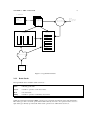
2.2 Agent Brain
At the heart of the Agent brain is a series of Stacks and the Opcode interpretor. The main function of the
Brain is to execute the opcodes and produce output. The basic structure of the brain is shown in Figure 2.2.
5
CHAPTER 2. EBPL LANGUAGE
6
OUTPUT
OpenGL
TIFF
Script
Compiled
OpCodes
Collision
Routines
Main
Flocking
Program
Global
Variables
STACK
BOOL
FUZZY
FLOAT
Vector Float
Fuzzy
VECTOR
POINT
Environment
Environment
Script
File
Figure 2.2: Agent Brain Structure
2.2.1 Brain Stacks
The Agent Brain has four built in stacks as follows :Float
A floating point stack.
Vector
A stack for operation on the Vector class.
Bool
A boolean stack.
Fuzzy
A stack for operation on the Fuzzy object class.
Unlike most interpretive languages EBPL operations are not entirely dependent upon the stack architecture.
Most data types can be accessed, queried and modified directly, however some operation such as access to
tuple data types still rely upon the stack. These stack operations are outlined in Section 2.3.1.
CHAPTER 2. EBPL LANGUAGE
7
2.2.2 Global Variables
When the Brain is loaded the variables defined in the brain script file are loaded in the form of a Variable
list. Each element of this list is a class called a VarObj as shown in Figure 2.3.
VarObj
+Float: float
+Bool: bool
+vect: Vector
+Point: Point3
+Fuzzy: fuzzy
+type: VarType
+Translate()
+Vertex()
+Normal()
+VarObj(Type:VARTYPE)
Figure 2.3: VarObj Class diagram
This object can assume any of the data type shown in Table 2.1 and has built in methods for specialist
OpenGL functions such as Vertex, Normal and Translate. These OpenGL operations only execute for the
Vector and Point classes.
2.2.3 Variables
At present five variable types are supported in EBPL, as shown in Table 2.1.
Variable Type
Float
Bool
Vector
Point
Fuzzy
Description
A signed floating point value
A boolean value
A four tuple vector class [x,y,z,w]
A three tuple Cartesian point class [x,y,z]
A full fuzzy logic class with fuzzy operators
Example
Float CentroidWeight=50.0;
Bool HitAgent=false;
Vector Dir=[0,-1,0,0];
Point Pos=[0,0,0];
Fuzzy NearAgent=0.2;
Table 2.1: EBPL variable types
The syntax of the variable definitions is tightly specified as shown in the Examples column of Table 2.1.
All variables must be initialized when declared and all have global scope to the Brain. This means that all
variables are available to all functions in the source file as well as accessible by other Agents.
2.2.4 Functions
EBPL has two types of Function these are built-in and user defined. There are 4 default built-in functions
which must be present in every EBPL script. The user may additionally create any number of Functions
within the program which act as procedure calls.
Built In Functions
InitFunction
UpdateFunction
DrawFunction
CollideFunction
Description
Called when the Agent brain is created and used to initialize variables etc.
Called every iteration of the system to update the Agents position
Called every iteration of the system to Draw the Agent
Called every iteration to do collision detection
Table 2.2: EBPL variable types
CHAPTER 2. EBPL LANGUAGE
8
The built-in functions are shown in Table 7.1 and are called for every Agent in the system for each iteration
of the environment.
User defined functions are generated by the Function keyword and can be called from within any of the
main built-in functions.
2.2.5 Call Lists
Call lists are a way of creating switchable function calls depending upon an ordinal variable value similar
to the C/C++ switch - case construct. The creation of a call list is a two stage process as follows :DefineCallList TestList;
CallListItem TestList foo;
CallListItem TestList bar;
First a call list name is defined to make storage for the Function pointers to be allocated to the list. Next
list items may be added to the list. To use a CallList within a Function the following code is used
float ListValue=0;
// function foo called
CallList TestList ListValue;
AddD ListValue 1;
// Function bar called
CallList TestList ListValue;
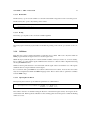
2.3 EBPL language structure
The EBPL language is split into four distinct parts, these are
Stack Based Operations.
Variable Operations.
Collisions.
Drawing.
2.3.1 Stack Operations
Each stack has a series of opcodes which can access the stack data. The operations are based upon the
stack data type and results from the operations are always placed back upon the stack. All stack operations
are prefixed with the stack type name as shown in Table 2.3.
Operator Prefix
F
FZ
B
V
Description
Float stack operator pre-fix
Fuzzy stack operator pre-fix
Boolean stack operator pre-fix
Vector stack operator pre-fix
Table 2.3: Stack Operation Prefix
For example to push an element of a vector onto the floating point stack the following code would be used.
CHAPTER 2. EBPL LANGUAGE
9
Vector Dir=[0,-1,0,0];
Fpush Dir y;
2.3.1.1 Float Stack Opcodes
The floating point stack operates in a First in Last Out principle, any operations on the stack use Reverse
Polish Notation (RPN). For example 2+3 will be executed in the script by Fpushd 3 Fpushd 2 Fadd which
will result in 5 being placed onto the top of the stack.
2.3.1.2 Fpush
The Fpush opcode pushes a floating value onto the stack. Any variable type may be pushed onto the stack,
however with tuple data types the element of the tuple to be pushed must be specified as shown in the
following example.
Fpush Pos x; // pushes the x component of the Point pos
Fpush yrot ; // pushes the float variable yrot;
Fpushd 10 ; // places 10 directly onto the stack
2.3.1.3 Fpop
The Fpop opcode takes the value from the top of the stack and places it into the variable, if a tuple data
type is used the x,y or z destination must be specified.
Fpop ypos; // places the tos value into ypos
Fpop tempPos y; places the tos value into tempPos.y
2.3.1.4 Fadd
The Fadd opcode takes the top two values from the stack adds them and places the sum back onto the stack
2.3.1.5 Fsub
The Fsub opcode takes the top two value from the stack subtracts them and places the result back on the
stack. Note if the stack contains 2 and 4 the result will be 2 - 4 = -2
2.3.1.6 Fmul
The Fmul opcode takes the two top values from the stack and multiplies them and places the product back
on the stack.
2.3.1.7 Fdiv
The Fdiv opcode takes the two top values from the stack and divides them and places the result back on the
stack. Division by 0 is trapped by changing any 0 value with a 1 (and printing a warning to the console in
debug mode).
CHAPTER 2. EBPL LANGUAGE
10
2.3.1.8 Fdup
The Fdup opcode takes the top of stack value and duplicates it.
2.3.1.9 Fsqrt
The Fsqrt opcode takes the top of stack value and places the square root of that value onto the stack.
2.3.1.10 Frad2Deg
The Frad2deg opcode is a helper function to convert radians to degrees as most C++ math operations use
radians.
2.3.1.11 Fatan
The Fatan opcode takes the two top values from the stack and calculates the arc tangent. The code used is
atan2(x,y) where X is the top of stack value and y is the next value.
2.3.1.12 Fsin
The Fsin opcode takes the top most value from the stack and puts back the sine of the value.
2.3.1.13 Fasin
The Fasin opcode takes the top most value from the stack and puts back the arc sine of the value.
2.3.1.14 Fcos
The Fcos opcode takes the top most value from the stack and puts back the cosine of the value.
2.3.1.15 Facos
The Facos opcode takes the top most value from the stack and puts back the arc cosine of the value
2.3.1.16 Fnegate
The Fnegate opcode takes the top most value from the stack and puts back the negated value.
2.3.1.17 FStackTrace
The FStackTrace opcode prints out the current contents of the stack.
CHAPTER 2. EBPL LANGUAGE
11
2.3.2 Variable Operations
All variables within EBPL have global scope and can be accessed within any Function. They can be set
directly or assigned a value based upon another variable.
The setting of individual tuple values can only be accomplished via the float stack as outlined in Section
2.3.1.
Variables may also be used in comparison if and ifelse operations. These may only be carried out with
variables of the same type and relies upon the overloaded comparison operators of Point and Vector classes.
As the comparison of the operators >, >=, <, <=, is ambiguous for Points and Vectors they have be defined
to work for all tuple values for example the Point >= operator is defined as
bool Point3 :: operator>=(Point3& v)
{
if(x>=v.x && y>=v.y && z>=v.z)
return true;
else return false;
}
2.3.3 Variable Opcodes
Most variables can be accessed directly by the use of opcodes and values can be set and retrieved. The
following section show the basics, full examples of all opcodes are shown in Section 7.11.
2.3.3.1 Add
The Add opcode works on any data type but care must be taken with the mixing of types. For example
tuple data types can be added together easily but a tuple to float will cause problems.
Add Pos Dir; // add a point to a vector
Add yrot zrot; // add two float variables
2.3.3.2 AddD
The AddD opcode adds a value directly to a variable for example
AddD yrot 180.0;
2.3.3.3 Length
The Length opcode returns the length of a Vector or Point Variable onto the stack.
2.3.3.4 Normalize
The Normalize opcode normalizes the current Vector or Point Variable.
CHAPTER 2. EBPL LANGUAGE
12
2.3.3.5 Randomize
The Randomize opcode sets the variable to a random value within a range based on the seed value passed.
The RandomizePos opcode only returns positive values.
Randomize Dir 2.1 0.1 1.1;
RandomizePos yrot 4.0;
2.3.3.6 Debug
The Debug opcode prints to the console the variable argument
Debug Pos;
The DebugOpOn and DebugOpOff enable and disable the printing of the current opcode name to the console.
2.3.4 Collisions
Each time the system is updated the Brain’s CollideFunction is called. This is the only time within an
EBPL program that the an Agent can access another Agent’s data.
Within the ebpl system all Agents are contained within a number of bins (see Section ??. for more details).
It is possible to loop through the Agents within the bins and test for collisions. This is implemented using
the LoopBin EBPL function.
Whenever the LoopBin structure is encountered the current Agent value is used and the rest of the Agents
within the bin are compared with the current Agent.
For convenience and speed EBPL has two built-in collision detection routines, however these and others
may also be implemented within the EBPL language itself. These routines take as parameters variables
from the EBPL script.
2.3.4.1 SphereSphereCollision
The SphereSphereCollision opcode takes five parameters as outlined below
SphereSphereCollision bool Hit Point3 Pos1 float Rad1
Point3 Pos2 float Rad2 ;
The collision detection is calculated using the Position of the Current Agent and any other Agents in the
current lattice bin. Each Agent has a Radius for the bounding sphere and if the spheres collide the Hit flag
will be set to true.
CHAPTER 2. EBPL LANGUAGE
13
2.3.4.2 CylinderCylinderCollision
The CylinderCylinderCollision opcode takes seven parameters as outlined below
CylinderCylinderCollision bool Hit Point3 Pos1 float Rad1 float Height1
Point3 Pos2 float Rad2 float Height2;
The collision detection is calculated using the Position of the Current Agent and any other Agents in the
current lattice bin. Each Agent has a Radius and Height for the bounding cylinder and if the cylinders
collide the Hit flag will be set to true.
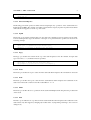
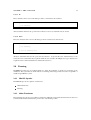
2.3.5 Environment Collisions
Collisions with objects within the environment are processed by two built-in functions. At present only
Planes and Cubes are supported.
2.3.5.1 Env Object Collisions
EnvObjects as shown in Figure 2.4. are represented as a cube with a bounding sphere. When the SphereEnvObjectCollision Opcode is used the parameters passed to the routine are checked against all of the EnvObjects contained within the environment.
Figure 2.4: Agents avoiding an EnvObj
CHAPTER 2. EBPL LANGUAGE
14
Detection of collision with EnvObjects is a two stage process, first the Agent is tested using Sphere-Sphere
collision as shown in Section 7.3.0.1. to determine if the Object has been hit. Next Sphere Plane collision
as shown in Section ??. is used to determine which face of the object has been hit. At present the Normal
of this face is returned to the Agent and collision avoidance is calculated on this value.
2.3.5.2 EnvObject Example
EnvObj’s are added to the environment using the following .fl script.
EnvObj float Pos.x float Pos.y float Pos.z
float Width float Height float Depth
float Radius
The radius parameter is used to determine the bounding sphere of the object for the collision detection used
in the SphereEnvObjCollision opcode.
The SphereEnvObjCollision opcode takes four parameters as outlined below
SphereEnvObjCollision bool Hit Point3 Pos
float Radius2 Vector Normal;
The collision detection is calculated using the Position of the Current Agent and its bounding sphere Radius,
each EnvObject is tested in turn against the Agent and if a hit is detected the Hit flag is set to true and the
Normal to the face hit is returned in the Normal parameter.
2.3.6 Structure Opcodes
The structure opcodes are used to define and call functions and make decisions.
2.3.6.1 Function
The Function Opcode defines the beginning of a function block. It must be terminated by use of an End
opcode as shown below
Function CalcAngle
Fpush yrot;
Fpop yrot;
End;
2.3.6.2 Call
The Call opcode will call a function within the script.
Call CalcAngle;
CHAPTER 2. EBPL LANGUAGE
15
2.3.6.3 If
The if structure can be used on all data types and is constructed as shown below
if dist > MinCentroidDist
{
// do something
}
All if statements must use the open and closed braces, however if statements may be nested.
2.3.6.4 ifelse
The ifelse structure can be used on all data type and is constructed as shown below
ifelse dist > MinCentroidDist
{
// do something
}
{
// else do something else
}
All ifelse statements must use the open and closed braces. At present the ifelse statement may not be
nested, however if statements may be placed within an ifelse structure. If multiple ifelse type structures are
required use the CallList mechanism as outlined in Section 7.5.
2.4 Drawing
The EBPL DrawFunction is a built-in function to allow the rendering of Agents for previewing of the
simulation. The system has two main methods for drawing either using a cut-down version of OpenGL or
a built in AgentRender system.
2.4.1 MiniGL Opcodes
The MiniGL Opcodes are split into 2 main areas
Affine Transforms
Drawing
2.4.2 Affine Transforms
The following Opcodes are responsible for transforms within the environment, all transforms are based on
a transformation matrix which can be preserved for each drawing routine.
CHAPTER 2. EBPL LANGUAGE
16
2.4.2.1 PushMatrix / PopMatrix
The PushMatrix and PopMatrix opcodes preserve the affine transformation stack an operate in a similar
way to the OpenGL matrix stack. Care must be taken when using these operations and PushMatrix /
PopMatrix opcodes must be matched else the outcome is undefined.
// create an empty transform stack
PushMatrix;
// draw stuff
// restore the transform stack
PopMatrix;
2.4.2.2 Rotations
The rotation opcode set the current rotation in the X, Y and Z axis, all drawable objects called after a
rotation opcode will be rotated by the amount of degrees specified. The Rotate opcodes are defined as
follows
RotateX float Degrees;
RotateY float Degrees;
RotateZ float Degrees;
At present the Rotate opcode only accepts a Float variable and not a direct floating value.
2.4.2.3 Scale
The Scale opcode scales in the X, Y and Z axis any drawable objects specified after the Scale is used. At
present the Scale opcode only accepts direct floating point values and not variables as shown in the example
below
//scale in X y and Z
Scale 5.0 6.0 5;
2.4.2.4 Translate
The Translate opcode translates the current drawing position from the current point of the transformation
matrix to a new point specified by either a Vector or Point variable as shown below
Translate Point NewPos;
Translate Vector NewPos;
2.4.3 Drawing Primitives
EBPL has three geometric drawing primitives these are Sphere, Cube and Cylinder.
CHAPTER 2. EBPL LANGUAGE
17
2.4.3.1 Sphere
The Sphere and SolidSphere opcodes draw a sphere using the current Colour. The syntax for these opcodes
are as follows
Sphere Float Radius Float slices Float Stacks;
SolidSphere Float Radius Float slices Float Stacks;
The Radius value may be either a EBPL variable or a direct floating point value as shown in the following
examples
Float Radius=2.0;
Sphere Radius 12 12;
SolidSphere 10 12 12;
2.4.3.2 Cube
The Cube opcode will draw a wire-frame cube of width, height and depth d where d is either a Float
variable or a direct float value as shown in the following examples
float Width=1.0;
Cube Width;
Cube 4.3;
2.4.3.3 Cylinder
The Cylinder opcode draws a wire-frame cylinder of Radius r and Height h where r and h are either a Float
variable or a direct float value as shown in the following examples
float Width=1.0;
float Height=0.5;
Cylinder Width Height;
Cylinder 4.3 2.5;
2.4.4 Line Drawing
The line drawing elements of the MiniGL opcodes allow for the setting of line style, colour and the drawing
of verticies.
2.4.4.1 Colour
The Colour opcode sets the current drawing colour for lines and primitives, it can take either a Point data
type using the x,y and z tuple values for Red, Green, and Blue or direct Float values as shown in the
following examples
// set
Point
Colour
// set
Colour
colour to red
ColourValue=[1,0,0];
ColourValue;
colour to white
1 1 1;
CHAPTER 2. EBPL LANGUAGE
18
2.4.4.2 Line and Point Size
The current line and point size can be set using the PointSize and LineSize opcodes these only take direct
float values and are valid until another call to PointSize and LineSize. The default value for both is 1.0.
// set the pointsize to 5.0
PointSize 5.0;
// set the linesize to 2.0
LineSize 2.0;
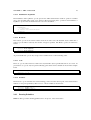
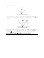
2.4.4.3 Drawing Styles
MiniGL supports five line drawing style as shown in Table 2.4
Value
Points
Lines
LineLoop
Polygon
Quads
Meaning
individual points
pairs of verticies interpreted as individual line segments
same as above, with a segment added between last and first verticies
boundary of a simple convex polygon
quadruples of verticies interpreted as four sided polygons
Table 2.4: Line Drawing styles[MW99]
These are shown in Figure 2.5.
Figure 2.5: MiniGL Line Drawing types
Each of these opcodes are called to specify the line drawing style for the verticies which follow, each of
the drawing styles must be ended by the use of the glEnd opcode as shown in the following example
// Draw using points
Points
Vertexf 0 0 0;
Vertexf 0 10 0;
glEnd;
CHAPTER 2. EBPL LANGUAGE
19
2.4.4.4 Vertex Commands
The drawing of individual verticies is carried out using the Vertex and Vertexf opcodes. The Vertex opcode
takes a Point or Vector variable as the argument whereas the Vertexf takes a direct floating point value for
the x, y and z values. These are shown in the following examples
// Draw a
LineLoop
Vertexf
Vertexf
Vertexf
glEnd;
triangle using direct values
0 0 0;
1 0 0;
1 -1 0;
// Draw a triangle using variables
Point P1=[0,0,0];
Point P2=[1,0,0];
Point P3=[1,-1,0];
LineLoop
Vertex P1;
Vertex P2;
Vertex P3;
glEnd;
2.4.4.5 Lighting
The current OpenGL lighting may be turned on and off using the LightingOn and LightingOff opcodes.
At present only the default OpenGL light GL_LIGHT0 (see [MW99] for more details) is enabled in the
system. Later version will allow for the full scripting of all available OpenGL lights.
2.4.5 MiniGL Example
Figure 2.6: Mini GL drawing
Figure 2.6. shows MiniGL in action rendering both the Boid type Agents and the ground shadows with the
ebpl code shown in Algorithm 1.
CHAPTER 2. EBPL LANGUAGE
20
Algorithm 1 MiniGL Drawing Example - Reynolds Boids [Rey87].
DrawFunction
PushMatrix;
// Translate to the Agents Position
Translate Pos;
//Rotate the Agent to the correct orientation
RotateX xrot;
RotateY yrot;
RotateZ zrot;
//Set the Colour
Colour 1.0 0.0 0.0;
//Now draw the agent poly’s
Polygon ;
Vertexf 0.5 -0.2 -0.2;
Vertexf 0.5 0.2 0.0;
Vertexf -0.5 -0.2 0.0;
Vertexf 0.5 -0.2 0.2;
Vertexf 0.5 0.2 0.0;
Vertexf -0.5 -0.2 0.0
glEnd ;
// Now draw the Poly’s as Lines to give the agent an outline shape
LineSize 1.0;
Colour 1.0 1.0 1.0;
LineLoop
Vertexf 0.5 -0.2 -0.2 ;
Vertexf 0.5 0.2 0.0 ;
Vertexf -0.5 -0.2 0.0 ;
Vertexf 0.5 -0.2 0.2 ;
Vertexf 0.5 0.2 0.0 ;
Vertexf -0.5 -0.2 0.0 ;
glEnd;
PopMatrix ;
// Now Draw Shadows
PushMatrix;
// preserve y value
Fpush Pos y;
PushGPYlevel;
Fpop Pos y;
Translate Pos;
RotateX xrot;
RotateY yrot;
RotateZ zrot;
Scale 0.5 0.5 0.5;
Colour 0.2 0.2 0.2;
Polygon ;
Vertexf 0.5 -0.2 -0.2 ;
Vertexf 0.5 0.2 0.0 ;
Vertexf -0.5 -0.2 0.0 ;
Vertexf 0.5 -0.2 0.2 ;
Vertexf 0.5 0.2 0.0 ;
Vertexf -0.5 -0.2 0.0 ;
glEnd;
PopMatrix;
// restore the Y value
Fpop Pos y;
End;
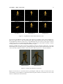
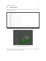
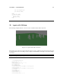
2.4.6 AgentRender
The AgentRender module allows for a series of key-framed Alias-wavefront .obj [Ali03] files to be loaded
as separate animation sequences which can be triggered within the system.
CHAPTER 2. EBPL LANGUAGE
21
Walk Mode 0
Run Mode 1
Neutral Mode 2
Dead Mode 3
Punch Mode 4
Swing Mode 5
Figure 2.7: AgentRender module with 6 animations cycles
At present the AgentRender module is hard coded with the six animation cycles shown in Figure 2.7.
However in future versions of the system this will be fully scripted within the .fl script system. Each time
the AgentRender module is loaded a series of OpenGL display lists are created to speed up the execution
of the renderer. If a non-accelerated OpenGL graphics card is used the system will resort back to software
rendering which slows down the loading and rendering of Agents.
When the AgentRender module is created the six animation cycles are created by loading in two .obj models
and creating a series of frames by the use of linear interpolation. Each model loaded in must have the same
vertex, face and normal layout but the verticies may be in different positions to create the animation.
Walk Start Frame
Walk End Frame
Figure 2.8: Sample Agent Render model frames
Figure 2.8 shows the two obj models used for generating the walk cycle. These are loaded as the start
and end frames for the animation cycle then the linear interpolation function shown below is used on each
Vertex to calculate the in-between frames
CHAPTER 2. EBPL LANGUAGE
22
glVertex3f( lerp(StartObj.Verts[V].x,EndObj.Verts[V].x,t),
lerp(StartObj.Verts[V].y,EndObj.Verts[V].y,t),
lerp(StartObj.Verts[V].z,EndObj.Verts[V].z,t));
Where t is the blend function set from 0, the start frame and 1 the end frame. The lerp function used is
shown below
GLfloat lerp(GLfloat A,GLfloat B, GLfloat t)
{
GLfloat p;
p=A+(B-A)*t;
return p;
}
2.4.6.1 Using the AgentRender
To use the AgentRender module both the .fl and brainscript files need to have the following instruction
added
UseAgentRender ;
This tells the environment and the Brain that the AgentRender is being used. If this is not present in the
scripts and any other AgentRender calls are made the system will crash. In the brain script this call is
generally placed in the InitFunction as it only needs to be set once.
There are four Opcodes used for configuring the AgentRender as follows
Value
SetAnimCycle
RenderFrame
RenderAgent
RenderMaterial
Meaning
sets the animation cycle to be drawn as indicated by the Mode values in Figure 2.7
Selects which frame of the AgentRender sequence to draw
Draws the Agent configured by the above two opcodes
Set the current material for the Agent (see Table 7.3)
Table 2.5: AgentRender Opcodes
All these opcodes can take either Float variables or direct float values as shown in the example below :// set to agent walk cycle
float DrawMode=0;
float Frame=4;
SetAnimCycle DrawMode;
// set material to chrome
RenderMaterial 3;
//render the 3rd frame of the cycle
RenderFrame Frame;
The material types currently used in EBPL are shown in Table 7.3.
CHAPTER 2. EBPL LANGUAGE
23
Material Number
0
1
2
3
4
5
6
7
8
Material Type
BLACKPLASTIC
BRASS
BRONZE
CHROME
COPPER
GOLD
PEWTER
SILVER
POLISHEDSILVER
Table 2.6: Material Types
Chapter 3
Programmable Particles
As well as emergent behaviour ebpl can generate user programmable particles for simple simulations.
This chapter presents a number of example ebpl brain scripts for generating a simple particle system and
highlight some of the basic principles of the ebpl language.
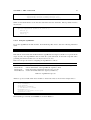
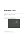
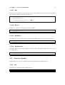
3.1 Simple Particles
One of the earliest method of controlling large amounts of objects in a scene is the Particle System introduced by Reeves [Ree83, Ree85] in 1983. When viewed as a whole the particles create the impression of
a single, dynamic, complex object [Par02] as shown in Figure 3.1.
Figure 3.1: Simple Particle system Created in EBPL
For a simple omni-directional particle system only a few variables are required as follows
Position - the particles current position.
NextPosition - the position where the particle will be next.
24
CHAPTER 3. PROGRAMMABLE PARTICLES
25
Direction - the direction of emission.
LifeSpan - the life of the particle.
For each iteration of the system the Direction is added to the current Position to give the particle movement.
The NextPosition is calculated by setting the current position after this calculation and then adding the
Direction again.
The Life variable is incremented by one each iteration and if it reaches the EndLife value the particle is
reset and re-emitted.
For each particle a random life and direction is created and the particles are drawn as lines as shown in the
following ebpl script.
Program 2: Particle.bs Simple Particle System
// the Particles Position
Point Pos=[0,0,0];
// Particles Direction
Vector Dir=[0.0,0.0,0.0,0.0];
// The Particles Next Position
Vector NextPos=[0.0,0.0,0.0,0.0];
// The Lifespan of the particle
float Life=0.0;
// When the particle is to Die
float EndLife=10.0;
// Default init function for the Agent Brain
InitFunction
Call InitParticle ;
End;
// Initialize the particle
Function InitParticle ;
// Create a random direction
Randomize Dir 1.0 1.0 1.0;
// Set the particles life value to 0
SetD Life 0.0;
// Set the initial position of the particle to 0,0,0
SetD Pos 0.0 0.0 0.0;
SetD NextPos 0.0 0.0 0.0;
// Randomize the particles life span
Randomize EndLife 20;
End;
// just draw the particle as a line from current pos to next pos
DrawFunction
PushMatrix;
// Translate to the Agents Position
Translate Pos;
Colour 1.0 1.0 1.0;
Lines ;
Vertex Pos;
Vertex NextPos;
glEnd;
PopMatrix;
End;
// update the particles position based on the Dir vector
UpdateFunction
Add Pos Dir;
Set NextPos Pos;
Add NextPos Dir;
AddD Life 1.0;
// if we have reached the end of the particle’s life reset it
if Life >= EndLife
CHAPTER 3. PROGRAMMABLE PARTICLES
26
{
Call InitParticle;
}
End;
// No collision detection
CollideFunction
End ;
3.2 Cone Emit Particles
Figure 3.2: Cone Emit Particles
The following example (Figure 3.2.) shows a particle system using a directional cone as the emitter. The
algorithm used is shown in Algorithm 2.
Algorithm 2 ConeEmitter modified from[jr01]
To emit a particle in a cone we define the EmitAngle to be in the range
Generate two random numbers and based on the EmitAngle.
The Direction vector is then calculated as follows :-
!"#$%&'
()*$+$
This can be converted into ebpl code as follows
CHAPTER 3. PROGRAMMABLE PARTICLES
27
Program 3: ConeEmitParticles.bs Particles Emitted in a Cone
float phi=0.0 ;
float theta=0.0 ;
float EmitAngle=3.1415926;
Function Emit ;
RandomizePos theta EmitAngle ;
RandomizePos phi EmitAngle ;
fpush theta ;
fsin ;
fpush phi ;
fcos ;
fmul ;
fpop EmitDir x ;
fpush theta ;
fsin ;
fpush phi ;
fsin ;
fmul ;
fpop EmitDir y ;
fpush theta ;
fcos ;
fpop EmitDir z ;
End ;
3.2.1 Wind vector
Figure 3.3: Cone Emit Particles with wind and different cone angle
Figure 3.3 shows the same system with a different EmitAngle and a Wind vector added to the x and y value
of each particle. The full source for this example is shown below
CHAPTER 3. PROGRAMMABLE PARTICLES
Program 4: ConeEmitParticles.fl Full Listing
// the particles position
Point Pos=[0,0,0] ;
Point NextPos=[0,0.0,0.0] ;
// life of the particle
float Life=0.0 ;
// particle end life
float EndLife=10.0 ;
//colour value for the particle
Point PColour=[1,1,1] ;
// the direction to emit the particle
Vector EmitDir=[0,0,0,0] ;
// wind vector to add to the particle
Vector Wind=[0.4,0,0.6,0] ;
// variable used to calculate emit direction
float phi=0.0 ;
float theta=0.0 ;
float EmitAngle=1.14159276 ;
//to emit we use the following algorithm
// D.x=cos(theta)*sin(phi)
//D.y =sin(theta)*sin(phi)
//D.z = cos(theta)
Function Emit ;
RandomizePos theta EmitAngle ;
RandomizePos phi EmitAngle ;
fpush theta ;
fsin ;
fpush phi ;
fcos ;
fmul ;
fpop EmitDir x ;
fpush theta ;
fsin ;
fpush phi ;
fsin ;
fmul ;
fpop EmitDir y ;
fpush theta ;
fcos ;
fpop EmitDir z ;
End ;
//initialise the particle
InitFunction ;
Call InitParticle ;
End ;
Function InitParticle ;
//set initial position to 0
SetD Pos 0 0 0 ;
SetD NextPos 0 0 0;
SetGlobalPos Pos ;
// create a random colour
RandomizePos PColour 1.0 1.0 1.0 ;
// reset the life
SetD Life 0.0 ;
// create a random life for the particle
RandomizePos EndLife 15 ;
// calculate the emit direction
Call Emit ;
End ;
DrawFunction ;
PushMatrix;
28
CHAPTER 3. PROGRAMMABLE PARTICLES
// Translate to the Agents Position
Translate Pos;
// set the colour
Colour PColour;
// draw the particle as a line
Lines ;
Vertex Pos;
Vertex NextPos;
glEnd;
PopMatrix;
End;
UpdateFunction ;
// move the particle
Add Pos EmitDir;
// add the wind
Add Pos Wind;
Set NextPos Pos;
Add NextPos EmitDir;
AddD Life 1.0;
// set the global pos so the particles get draw in all views
SetGlobalPos Pos;
// are we dead yet
if Life >= EndLife
{
// create a new particle
Call InitParticle ;
}
End ;
CollideFunction ;
End ;
3.3 Projectile Motion Particles
Figure 3.4 shows a series of spheres using the equations for projectile motion outlined in Algorithm 3.
Figure 3.4: Projectile particles
29
CHAPTER 3. PROGRAMMABLE PARTICLES
30
Algorithm 3 Projectile Motion modified from [Len01]
The position ,-. of a= projectile having initial position /10 and initial velocity 243 at time t=0 is given
5 .6*/7398:207.8<=; > . where gravity > @? ACBDFE assuming the Y axis is upward and A *GIH JLKNMLO = by
BQ and R components of 5 may be calculated at any time . by the
From the above equation values for the P
following expressions :-
PSQ #.T/ 8U2 . =
Y .V/WX8U2 . $=; > .
.V/ ( 8U2 ( .
This can be implemented using the following ebpl code
// pre-calculate 1/2 G for speed
float Gravity=-4.9;
Function CalcProjectileMotion ;
//calc x
fpush Pos x;
fpush Velocity x;
fpush Time;
fadd;
fadd;
fpop Pos x;
//calc z
fpush Pos z;
fpush Velocity z;
fpush Time;
fadd;
fadd;
fpop Pos z;
// do t^2
fpush Time;
fdup;
fmul;
fpush Gravity;
fmul;
fpush Time;
fpush Pos y;
fmul;
fsub;
fpop Pos y;
End;
And the full program listing is as follows
Program 5: ProjectileParticle.bs Projectile particles
// the particles position
Point Pos=[0,0,0] ;
// wind vector to add to the particle
Vector Wind=[0.0,0,0.0,0] ;
float Time=1.0;
float EndTime=0.4;
Vector Velocity=[0,0,0,0];
//initialise the particle
InitFunction ;
Call InitParticle ;
End ;
Function InitParticle ;
//set initial position to 0
SetD Pos 0 0 0 ;
CHAPTER 3. PROGRAMMABLE PARTICLES
SetGlobalPos Pos ;
RandomizePos Time 1.0;
Randomize Wind 1 1 1;
Randomize Velocity 1 1 1;
End ;
DrawFunction ;
PushMatrix;
Colour 1 1 1;
Cube 2.0;
// draw a line from the origin to the particle
Lines;
Vertex Pos;
Vertexf 0 0 0;
glEnd;
// Translate to the Agents Position
Translate Pos;
EnableLights;
Colour 1.0 1.0 0.0;
Sphere 0.4 12 12;
DisableLights;
PopMatrix;
End;
// half gravity
float Gravity=-4.65;
Function CalcProjectileMotion ;
fpush Pos x;
fpush Velocity x;
fpush Time;
fadd;
fadd;
fpop Pos x;
fpush Pos z;
fpush Velocity z;
fpush Time;
fadd;
fadd;
fpop Pos z;
// calculate y do t^2
fpush Time;
fdup;
fmul;
fpush Gravity;
fmul;
fpush Time;
fpush Pos y;
fmul;
fsub;
fpop Pos y;
End;
UpdateFunction ;
// move the particle
SubD Time 0.01;
Call CalcProjectileMotion;
Add Pos Wind;
// set the global pos so the particles get draw in all views
SetGlobalPos Pos;
// are we dead yet
if Time <= EndTime
{
Call InitParticle ;
}
End ;
CollideFunction ;
End ;
31
Chapter 4
Flocking
In 1987 Reynolds [Rey87] extended the original Reeves [Ree83, Ree85] particle system into a “sub-object
system” where each particle, represented by a point in the Reeves system, is replaced by an animated object.
Each of these objects which Reynolds refers to as “Bird-oids” or “Boids” are given limited intelligence
which when combined into a collective whole produces the flocking behaviour.
The original Boids have three simple rules :1. Collision Avoidance : avoid collisions with nearby flock mates.
2. Velocity Matching : attempt to match velocity with nearby flock-mates
3. Flock Centering : attempt to stay close to nearby flock-mates.
Combining these rules produce a simple flocking behaviour as shown in figure 4.3
Figure 4.1: A simple Flock [Rey87]
32
CHAPTER 4. FLOCKING
33
In more recent papers Reynolds has introduced slightly different rules for his flocking behaviours calling
them “steering behaviours” [Rey99]. The new rules are
Separation : steer to avoid crowding local flock mates.
Alignment : steer towards the average heading of local flock mates.
Cohesion : steer to move toward the average position of local flock mates.
Separation
Alignment
Cohesion
Figure 4.2: Steering Flocking rules [Rey99]
These behaviours are shown in Figure 4.2 and create a different type of flocking to the original rules.
4.1 A simple Flock in ebpl
Figure 4.3 shows a simple flock using the rules outlined in the previous section.
Figure 4.3: A simple Flock
The flock is programmed to follow the flock center attached to the path but to avoid collisions with each
other and match speed.
Each Agent has a number of variables used to determine it’s Position and orientation. These are as follows
CHAPTER 4. FLOCKING
34
Pos - The agents position
NextPos - Where the Agent will be in the Next cycle (used for collision detection and orientation)
CentroidWeight - how much the agent should try to move to the flock center
MinCentroidDist - how far the Agent should move away from the flock center before turning back
FlockAvoidWeight - how much the Agent should try to avoid the other Agents
Radius - the bounding sphere radius of the Agent used for collision detection
HitAgent - a flag to indicate if the Agent has collided
When the simulation is executed the Agents are emitted in a random direction, once the flocking mode is
turned on using the space key the Agents will try to head towards the flock center.
Next the Agents are tested for collisions, if there is a collision the Average direction of both Agents is
calculated and the Agents new direction is set to this. This allows the Agents to merge together and match
velocity.
Finally the orientation of the Agent is calculated using Spherical geometry as shown in Section 4.1.0.1
4.1.0.1 Using spherical geometry to calculate Agent orientation
Figure 4.4: Spherical Geometry[jr01]
Figure 4.4 shows how a point Z is defined in spherical coordinates.
[
is the radial distance of Z
the latitude of the point Z .
from the origin, and
is the azimuth of Z , the angle between the P
lies in the interval
X M]\_^`Na M]\
Q
is the angle that
Z
PY
makes with the
-plane, know as
Q
-plane and the plane through Z and the -axis.
and lies in the range
^ba`\ Using trigonometry we can work out a relationship between spherical coordinates and Cartesian coordiB B
nates cd cW cCe1 for Z the equations are
cdf [gh O gh O$#$ B cCW [ O+ikjV B and cel [gh O'C%O+i'jV#$
Using trigonometry we can work out a relationship between Cartesian coordinates and spherical coordinates as follows
[ @m c = 8Uc = 8nc = ; oO+ikjqp ;rts1v
u wyx z{$| g .}{jV#cCe B cd$
d W e
The function arctan(,) is the two argument form of the arctangent, defined as (atan2 in C++)
CHAPTER 4. FLOCKING
~
Q MFPC
.
}
$
{
q
j
p
}
i
:
N
P
;
Q
8U}. {jqp ; MFPC
g
Q
B
}
i
:
N
P
a
{ | .}{jV PT
}i :P
{$j4 QQ X ]M ML\ \
}i :P
{$j4 a
This may be implemented in C++ using the following code
void Agent::CalcAngle(void)
{
GLfloat X,Y,Z;
X=NextPos.x-Pos.x;
Z=NextPos.z-Pos.z;
Y=Pos.y-NextPos.y;
//using spherical geometry we calculate the rotation based on the New Point
yrot=atan2(Z,X); // Now convert from radians to deg
yrot=-((yrot/TWO_PI)*360.0f); //now align the geometry to our world
yrot+=180;
// Now for the zrot
GLfloat r=sqrt(X*X+Y*Y+Z*Z);
zrot=asin(Y/r);
//convert from radians to deg
zrot=((zrot/TWO_PI)*360.0f);
}
The following code does the same using the ebpl language
Vector tmpPos=[0,0,0,0];
Vector tmpPos2=[0,0,0,0];
Function CalcAngle;
// fist set the vectors to subtract
Set tmpPos NextPos ;
Sub tmpPos Pos;
Fpush tmpPos x ;
Fpush tmpPos z ;
// use atan2 to calc the angle
fatan ;
// this gives us the angle in radians so we convert it
Frad2deg ;
// finally we align it with the world geometry
Fnegate ;
Fpop yrot ;
AddD yrot 180.0 ;
// now we align the z rotation
//Y=Pos.y-NextPos.y;
Set tmpPos NextPos ;
Set tmpPos2 Pos ;
// swap the y components
Fpush Pos y ;
Fpop tmpPos y;
Fpush NextPos y ;
Fpop tmpPos2 y ;
// now subtract the two
Sub tmpPos tmpPos2 ;
//zrot=asin(Y/r);
Length tmpPos ;
Fpush tmpPos y ;
Fdiv ;
fasin ;
// convert it to degrees
frad2deg;
Fpop zrot;
End;
35
CHAPTER 4. FLOCKING
36
4.1.0.2 Simple Flock program using ebpl
The following code is used to control the Agent for the simple flock example
Program 6: SimpleFlock.bs Simple flocking system
// the Agents position
Point Pos=[0,0,0];
Vector Dir=[0.0,-0.2,-0.1,0.0];
Point NextPos=[0,0.0];
bool TRUE=true;
bool FALSE=false;
// The rotation of the Agent in the X plane
float xrot=0.0;
float yrot=0.0;
// The rotation of the Agent in the Z plane
float zrot=0.0;
// Vector ADir is the Average direction of the Agent calculated from hits with any agents
//in the current bounding sphere radius. This is used with the FlockAvoidDir
// weight to set the Flock avoid Direction
Vector ADir=[0,0,0,0]; //flock avoid dir
// Vector CentroidDir is the direction to the flock center from the current agent position.
//This is multiplied by the Centroid weight */
Vector CentroidDir=[0,0,0,0];
// bool HitAgent boolean flag set to indicate that the Agent has hit another Agent */
bool HitAgent=false;
// GLfloat GPYlevel the ground plane level of the Agent */
float GPYlevel=-18;
// GLfloat CentroidWeight The weight the CentroidDir vector is multiplied by to calculate
//the new direction of the Agent so it can flock center */
float CentroidWeight=20.0;
//GLfloat FlockAvoidWeight The Weight the FlockAvoidDir vector is multiplied by to calculate
//the new direction of the Agent when it has hit a member of it’s own flock */
float FlockAvoidWeight=99.0;
float Radius=4.1;
// GLfloat Hunger will be used to make Agent hunt for food when hungry
float MinCentroidDist=10.0;
Vector CentroidDist=[0,0,0,0] ;
Point Centroid=[0,0,0] ;
InitFunction
Randomize Dir 2.0 2.0 2.0;
SetGlobalPos Pos;
RandomizePos MinCentroidDist 28;
End;
DrawFunction
PushMatrix;
// Translate to the Agents Position
Translate Pos;
//Rotate the Agent to the correct orientation
RotateX xrot;
RotateY yrot;
RotateZ zrot;
//Set the Colour
Colour 1.0 0.0 0.0;
Polygon ;
Vertexf 0.5 -0.2 -0.2;
Vertexf 0.5 0.2 0.0;
Vertexf -0.5 -0.2 0.0;
Vertexf 0.5 -0.2 0.2;
Vertexf 0.5 0.2 0.0;
Vertexf -0.5 -0.2 0.0
glEnd ;
// Now draw the Poly’s as Lines to give the agent an outline shape */
CHAPTER 4. FLOCKING
LineSize 1.0;
Colour 1.0 1.0 1.0;
LineLoop
Vertexf 0.5 -0.2 -0.2 ;
Vertexf 0.5 0.2 0.0 ;
Vertexf -0.5 -0.2 0.0 ;
Vertexf 0.5 -0.2 0.2 ;
Vertexf 0.5 0.2 0.0 ;
Vertexf -0.5 -0.2 0.0 ;
glEnd
PopMatrix ;
End;
float Ylevel=0.0;
UpdateFunction
Set HitAgent FALSE;
Call UpdateAgainstCentroid ;
Mul ADir FlockAvoidWeight;
Mul CentroidDir CentroidWeight;
Add Dir ADir;
Add Dir CentroidDir;
Normalize Dir;
fpush Pos y ;
fpop Ylevel ;
Add Pos Dir ;
Set NextPos Pos ;
Add NextPos Dir ;
Call CalcAngle ;
SetGlobalPos Pos;
SetD ADir 0 0 0;
SetD CentroidDir 0 0 0;
if Ylevel <= GPYlevel
{
SetD Dir y 1;
}
End;
float dist=0.0;
Function UpdateAgainstCentroid;
GetGlobalCentroid Centroid;
Set CentroidDist Centroid;
Sub CentroidDist Pos;
Length CentroidDist ;
fpop dist ;
if dist >= MinCentroidDist;
{
Set CentroidDir Centroid ;
Sub CentroidDir Pos;
}
End;
// This function calculates the Agents orientation based on the pos
// and the NextPos
// use these for temp storage in the calc angle function
Vector tmpPos=[0,0,0,0];
Vector tmpPos2=[0,0,0,0];
Function CalcAngle;
// fist set the vectors to subtract
Set tmpPos NextPos ;
Sub tmpPos Pos;
Fpush tmpPos x ;
Fpush tmpPos z ;
// use atan2 to calc the angle
fatan ;
// this gives us the angle in radians so we convert it
Frad2deg ;
// finally we align it with the world geometry
Fnegate ;
Fpop yrot ;
37
CHAPTER 4. FLOCKING
38
AddD yrot 180.0 ;
// now we align the z rotation
//Y=Pos.y-NextPos.y;
Set tmpPos NextPos ;
Set tmpPos2 Pos ;
// swap the y components
Fpush Pos y ;
Fpop tmpPos y;
Fpush NextPos y ;
Fpop tmpPos2 y ;
// now subtract the two
Sub tmpPos tmpPos2 ;
//zrot=asin(Y/r);
Length tmpPos ;
Fpush tmpPos y ;
Fdiv ;
fasin ;
// convert it to degrees
frad2deg;
Fpop zrot;
End;
CollideFunction
LoopBin ;
SphereSphereCollision HitAgent Pos Radius NextPos Radius;
if HitAgent == TRUE;
{
// calc average
GetAgentI ADir Dir;
Add ADir Dir;
DivD ADir 2;
Normalize ADir;
Set Dir ADir;
SetAgentI Dir ADir;
}
LoopBinEnd;
End ;
And the ebpl .fl script for the configuration of the environment
// Configure the bounding box for the simulation
WorldBBox 0 0 0 80.0 80.0 80.0 2 2 2 20
// specify the output file to read to
outputfile outfile.out
// create a camera to view the scene
Camera 0 80 40 0 0 0 0 1 0 800 660 45.0 1.33 0.1 450.0
// Create an emitter for the Agent with 50 Agents
AgentEmitter 0.0 0.0 0.0 50 0 0 0.0 0.0 0 0 SimpleFlock.comp
// Specify a path
PathFollow 0 -20 0 2 -10 -30 -5 -20 1 -4 25 -2 -5
// Specify the ground plane
GroundPlane -20 0 0.4 0 0.5
4.2 Advanced Flocking
Figure 4.5 shows a flock of fifty Agents using a different Agent avoid algorithm and Perlin noise [eta98]
turbulence based on the Agents Position.
CHAPTER 4. FLOCKING
39
Figure 4.5: A flock using complex avoidance and noise functions
The Agents have a number of built in weights and vectors as in the previous example. However the Agents
use a different avoid function as shown in the following section.
4.2.0.3 Agent Avoidance routine
Algorithm 4 shows the new collision avoidance algorithm used in the new flocking system based on the
calculation of reflected rays normal to a surface. Algorithm 5 shows the ebpl code for the routine.
CHAPTER 4. FLOCKING
40
Algorithm 4 Collision avoidance algorithm adapted from [jr01, Len01]
;
The above figure shows the movement of an Agent having a direction
hitting the Agent Normal and
reflecting in (an as yet unknown) direction . The vector is perpendicular to the line. Angle must
;
equal angle =
The above figure shows
resolved into a portion along and a portion orthogonal to 6H Because of
B
symmetry, has the same component orthogonal to but the opposite component along so f*
Because
it follows that @
\] . Now is the orthogonal projection of
onto so we
can get t D @
remember that is a unit vector in the direction of
\#
q which is the direction of the reflected Agent.
From this we obtain the result
This is then repeated for Agent 2 to determine the new direction for the other Agent.
CHAPTER 4. FLOCKING
41
Algorithm 5 ebpl Code for Agents reflection
This is shown in the following ebpl code
Point TempP=[0,0,0];
Vector Norm=[0,0,0,0];
Point P1=[0,0,0,0];
Point P2=[0,0,0,0];
float x=0.0;
float two=2.0;
Vector d=[0,0,0,0];
Vector NDir=[0,0,0,0];
CollideFunction
LoopBin ;
SphereSphereCollision HitAgent Pos Radius2 NextPos Radius2;
ifelse HitAgent == TRUE;
{
GetAgentI P1 Pos ;
GetAgentI
P2 NextPos ;
Set Norm P2;
Sub Norm P1;
Dot x P1 P2;
Mul x two;
Set d Norm;
Mul d x;
Set NDir Dir;
Sub d NDir;
Set ADir NDir;
Set P1 Pos;
Set P2 NextPos ;
Set Norm P2;
Sub Norm P1;
Dot x P1 P2;
Mul x two;
Set d Norm;
Mul d x;
GetAgentI NDir Dir;
Sub d NDir;
SetAgentI NDir ADir;
SetD CentroidWeight 0;
SetD CentroidDir 0 0 0;
SetD FlockAvoidWeight 100;
}
{
SetD CentroidWeight 100;
SetD FlockAvoidWeight 50;
}
LoopBinEnd;
End ;
4.2.0.4 Noise Function
Each Agent has the ability to access a noise function based on Perlin Noise [eta98]. This value is generated
by a built-in noise function and can be calculated from any tuple data type. There are five built in noise
functions as shown in Table 7.4
CHAPTER 4. FLOCKING
42
Noise Type
turbulence
marble
undulate
noise3
turbulence2
Noise Index Value
0
1
2
3
4
Table 4.1: ebpl Noise functions
To use noise the noise generator must be initialized as follows
float NoiseType=5.0;
float NoiseScale=0.0;
RandomizePos NoiseType 5;
Randomize NoiseScale 2000;
UseNoise NoiseType NoiseScale;
The GetNoiseValue opcode is used to access the noise table, it is passed a value to return to and a seed
value to generate the noise from this is shown in the following example.
Point Pos=[0,0,0];
Vector NoiseValue=[0,0,0,0];
GetNoiseValue NoiseValue Pos;
4.2.0.5 Complex Flock ebpl code
The following code shows the Agent brain code for the Complex Flock example
Program 7: ComplexFlock.bs Flock using Noise
// the Agents position
Point Pos=[0,0,0];
Vector Dir=[0.0,-0.2,-0.1,0.0];
Point NextPos=[0,0.0];
bool TRUE=true;
bool FALSE=false;
// The rotation of the Agent in the X plane
float xrot=0.0;
float yrot=-90.0;
// The rotation of the Agent in the Z plane
float zrot=0.0;
// Vector ADir is the Average direction of the Agent calculated from hits with
//any agents
// in the current bounding sphere radius. This is used with the FlockAvoidDir
// weight to set the
// Flock avoid Direction */
Vector ADir=[0,0,0,0]; //flock avoid dir
// Vector CentroidDir is the direction to the flock center from the current agent
//position.
//This is multiplied by the Centroid weight */
Vector CentroidDir=[0,0,0,0];
// bool HitAgent boolean flag set to indicate that the Agent has hit another
// Agent
CHAPTER 4. FLOCKING
bool HitAgent=false;
// GLfloat GPYlevel the ground plane level of the Agent
float GPYlevel=-38;
// GLfloat CentroidWeight The weight the CentroidDir vector is multiplied by to
// calculate
//the new direction of the Agent so it can flock center
float CentroidWeight=100.0;
//GLfloat FlockAvoidWeight The Weight the FlockAvoidDir vector is multiplied by
//to calculate
//the new direction of the Agent when it has hit a member of it’s own flock
float FlockAvoidWeight=100.0;
float Radius=2.0;
float Radius2=1.5;
// GLfloat Hunger will be used to make Agent hunt for food when hungry
float MinCentroidDist=10.0;
Vector CentroidDist=[0,0,0,0] ;
Vector nVel=[0,0,0,0];
Vector acceleration=[1,1,1,0];
Vector force=[0,0,0,0];
Vector mass=[150,150,150,0];
Vector EnvAvoidDir=[0,0,0,0];
Vector Velocity=[0,0,0,0];
Vector VelDiv=[1,1,1,0];
float NoiseType=2.0;
float NoiseScale=1230.0002;
Point Centroid=[0,0,0] ;
float Ylevel=0.0;
float dist=0.0;
InitFunction
Randomize Dir 2.0 2.0 2.0;
SetGlobalPos Pos;
RandomizePos MinCentroidDist 28;
AddD MinCentroidDist 4;
RandomizePos CentroidWeight 50;
RandomizePos NoiseType 5;
Randomize NoiseScale 2000;
UseNoise NoiseType NoiseScale;
End;
DrawFunction
PushMatrix;
// Translate to the Agents Position
Translate Pos;
//Rotate the Agent to the correct orientation
RotateX xrot;
RotateY yrot;
RotateZ zrot;
//Set the Colour
//Now draw the agent poly’s
Colour 1.0 0.0 0.0;
Polygon ;
Vertexf 0.25 -0.1 -0.1;
Vertexf 0.25 0.1 0.0;
Vertexf -0.25 -0.1 0.0;
Vertexf 0.25 -0.1 0.1;
Vertexf 0.25 0.1 0.0;
Vertexf -0.25 -0.1 0.0
glEnd ;
// Now draw the Poly’s as Lines to give the agent an outline shape */
LineSize 1.0;
Colour 1.0 1.0 1.0;
LineLoop
Vertexf 0.25 -0.1 -0.1 ;
Vertexf 0.25 0.1 0.0 ;
Vertexf -0.25 -0.1 0.0 ;
Vertexf 0.25 -0.1 0.1 ;
Vertexf 0.25 0.1 0.0 ;
Vertexf -0.25 -0.1 0.0 ;
43
CHAPTER 4. FLOCKING
glEnd;
PopMatrix ;
PushMatrix;
// preserve y value
Fpush Pos y;
PushGPYlevel;
Fpop Pos y;
Translate Pos;
RotateX xrot;
RotateY yrot;
RotateZ zrot;
Scale 0.5 0.5 0.5;
Colour 0.2 0.2 0.2;
Polygon ;
Vertexf 0.25 -0.1 -0.1 ;
Vertexf 0.25 0.1 0.0 ;
Vertexf -0.25 -0.1 0.0 ;
Vertexf 0.25 -0.1 0.1 ;
Vertexf 0.25 0.1 0.0 ;
Vertexf -0.25 -0.1 0.0 ;
glEnd;
PopMatrix;
fPop Pos y;
End;
Function UpdateAgainstCentroid;
GetGlobalCentroid Centroid;
Set CentroidDist Centroid;
Sub CentroidDist Pos;
Length CentroidDist ;
fpop dist ;
ifelse dist >= MinCentroidDist;
{
GetGlobalCentroid CentroidDir ;
Sub CentroidDir Pos;
}
{
SetD CentroidDir 0 0 0;
}
End;
// This function calculates the Agents orientation based on the position
// and the NextPos
// use these for temp storage in the calc angle function
Vector tmpPos=[0,0,0,0];
Vector tmpPos2=[0,0,0,0];
Function CalcAngle;
// fist set the vectors to subtract
Set tmpPos NextPos ;
Sub tmpPos Pos;
Fpush tmpPos x ;
Fpush tmpPos z ;
// use atan2 to calc the angle
fatan ;
// this gives us the angle in radians so we convert it
Frad2deg ;
// finally we align it with the world geometry
Fnegate ;
Fpop yrot ;
AddD yrot 180.0 ;
// now we align the z rotation
//Y=Pos.y-NextPos.y;
Set tmpPos NextPos ;
Set tmpPos2 Pos ;
// swap the y components
Fpush Pos y ;
44
CHAPTER 4. FLOCKING
Fpop tmpPos y;
Fpush NextPos y ;
Fpop tmpPos2 y ;
// now subtract the two
Sub tmpPos tmpPos2 ;
//zrot=asin(Y/r);
Length tmpPos ;
Fpush tmpPos y ;
Fdiv ;
fasin ;
// convert it to degrees
frad2deg;
Fpop zrot;
End;
Point TempP=[0,0,0];
Vector Norm=[0,0,0,0];
Point P1=[0,0,0,0];
Point P2=[0,0,0,0];
float x=0.0;
float two=2.0;
Vector d=[0,0,0,0];
Vector NDir=[0,0,0,0];
CollideFunction
LoopBin ;
SphereSphereCollision HitAgent Pos Radius2 NextPos Radius2;
ifelse HitAgent == TRUE;
{
GetAgentI
P1 Pos ;
GetAgentI
P2 NextPos ;
Set Norm P2;
Sub Norm P1;
Dot x P1 P2;
Mul x two;
Set d Norm;
Mul d x;
Set NDir Dir;
Sub d NDir;
Set ADir NDir;
Set P1 Pos;
Set P2 NextPos ;
Set Norm P2;
Sub Norm P1;
Dot x P1 P2;
Mul x two;
Set d Norm;
Mul d x;
GetAgentI NDir Dir;
Sub d NDir;
SetAgentI NDir ADir;
SetD CentroidWeight 0;
SetD CentroidDir 0 0 0;
SetD FlockAvoidWeight 100;
}
{
SetD CentroidWeight 100;
SetD FlockAvoidWeight 50;
}
LoopBinEnd;
End ;
float gpy=0.0;
UpdateFunction
SetGlobalCollideFlag FALSE;
SetGlobalPos Pos;
Call Move;
Call UpdateAgainstCentroid;
Call CalcDir;
45
CHAPTER 4. FLOCKING
Call CalcAngle;
PushGPYlevel;
fpop gpy;
fpush Pos y ;
fpop Ylevel ;
SetGlobalPos Pos;
SetD ADir 0 0 0;
SetD CentroidDir 0 0 0;
SetD EnvAvoidDir 0 0 0;
End;
vector NoiseValue=[0,0,0,0];
Function Move;
Set acceleration force;
Div acceleration mass;
Add Velocity acceleration;
Set nVel Velocity;
Div nVel VelDiv;
Add Pos Dir;
Mul Pos nVel;
Set NextPos Pos;
Add NextPos Dir;
Mul NextPos nVel;
Set ADir Dir;
End;
Function CalcDir;
Mul ADir FlockAvoidWeight;
Mul CentroidDir CentroidWeight;
Set Dir ADir;
Add Dir CentroidDir;
GetNoiseValue NoiseValue Pos;
Add Dir NoiseValue;
Normalize Dir;
//Set the force to be the current Direction so we can calculate the new
//acceleration
//in the next iteration
Set force Dir;
//Store the Average dir to be the current dir
//Set ADir Dir;
End;
46
CHAPTER 4. FLOCKING
47
4.3 Avoiding Objects
Figure 4.6 shows five hundred Agents avoiding a series of EnvObj objects. The environment is configured
using the following .fl script.
WorldBBox 0 0 0 80.0 80.0 40.0 5 2 5 520
OutputFile birds.out
OutFileFrameSkip 1
UpdateRate 1
Camera 0 80 0 0 0 0 0 0 1 800 660 45.0 1.33 0.1 450.0
Randomize
GroundPlane -20 0 0.4 0 0.7
EnvObj 0.0 0.0 0.0 6.0 6.0 6.0 5.0
EnvObj -20.0 0.0 0.0 6.0 6.0 6.0 5.0
EnvObj 20.0 0.0 0.0 6.0 6.0 6.0 5.0
EnvObj 0.0 -6.0 0.0 6.0 6.0 6.0 5.0
EnvObj -20 -6.0 0.0 6.0 6.0 6.0 5.0
EnvObj 20.0 -6.0 0.0 6.0 6.0 6.0 5.0
EnvObj 0.0 -12.0 0.0 6.0 6.0 6.0 5.0
EnvObj -20 -12 0.0 6.0 6.0 6.0 5.0
EnvObj 20.0 -12.0 0.0 6.0 6.0 6.0 5.0
EnvObj 0.0 -18.0 0.0 6.0 6.0 6.0 5.0
EnvObj -20 -18 0.0 6.0 6.0 6.0 5.0
EnvObj 20.0 -18.0 0.0 6.0 6.0 6.0 5.0
AgentEmitter -30.0 0 0 520 0.7 0.3 0.33 0.6 0 0 EnvObj.comp
PathFollow 0 -20 0 0 -10 0 0 10 0 0 20 0 0
lockedCentroid 0 0 0 0
Figure 4.6: Agents Avoiding Objects
The Agents again have a series of Variables as in the previous examples but the interaction with the EnvObj
objects are handled by the function CollideAgainstEnvOb
CHAPTER 4. FLOCKING
48
Function CollideAgainstEnvObj;
SphereEnvObjCollision HitEnvObj NextPos Radius2 EnvAvoidDir;
if HitEnvObj == TRUE;
{
SetD CentroidWeight 0;
SetD FlockAvoidWeight 10.0;
SetD EnvAvoidWeight 6129.0;
Randomize EnvNoise 0.2 0.2 0.2;
Add EnvAvoidDir EnvNoise;
}
if HitEnvObj == FALSE;
{
SetD CentroidWeight 72.9;
SetD FlockAvoidWeight 5100.0;
SetD EnvAvoidWeight 6120.0;
}
End;
Program 8: EnvObj.bs Avoiding Environment Objects
// the Agents position
Point Pos=[-30,0,0];
Vector Dir=[0.0,0.0,0.0,0.0];
Point NextPos=[0,0.0];
bool TRUE=true;
bool FALSE=false;
// The rotation of the Agent in the X plane
float xrot=0.0;
float yrot=-90.0;
// The rotation of the Agent in the Z plane
float zrot=0.0;
// Vector ADir is the Average direction of the Agent calculated from hits with any agents
// in the current bounding sphere radius. This is used with the FlockAvoidDir
// weight to set the Flock avoid Direction
Vector ADir=[0,0,0,0]; //flock avoid dir
// Vector CentroidDir is the direction to the flock center from the current agent position.
//This is multiplied by the Centroid weight
Vector CentroidDir=[0,0,0,0];
// bool HitAgent boolean flag set to indicate that the Agent has hit another Agent
bool HitAgent=false;
bool HitEnvObj=false;
// GLfloat GPYlevel the ground plane level of the Agent
float GPYlevel=-20;
// GLfloat CentroidWeight The weight the CentroidDir vector is multiplied by to calculate
//the new direction of the Agent so it can flock center
float CentroidWeight=72.9;
//GLfloat FlockAvoidWeight The Weight the FlockAvoidDir vector is multiplied by to calculate
//the new direction of the Agent when it has hit a member of it’s own flock
float FlockAvoidWeight=5100.0;
float EnvAvoidWeight=6129.0;
float Radius=0.6;
float Radius2=2.1;
float MinCentroidDist=6.0;
Vector CentroidDist=[0,0,0,0] ;
Vector nVel=[0,0,0,0];
Vector acceleration=[1,1,1,0];
Vector force=[0,0,0,0];
Vector mass=[150,150,150,0];
Vector EnvAvoidDir=[0,0,0,0];
Vector Velocity=[0,0,0,0];
Vector VelDiv=[1,1,1,0];
float NoiseType=2.0;
CHAPTER 4. FLOCKING
49
float NoiseScale=1230.0002;
vector NoiseValue=[0,0,0,0];
InitFunction
Randomize Dir 2.0 2.0 2.0;
SetGlobalPos Pos;
RandomizePos NoiseType 5;
Randomize NoiseScale 2000;
UseNoise NoiseType NoiseScale;
End;
Point Centroid=[10,10,0] ;
DrawFunction
PushMatrix;
// Translate to the Agents Position
Translate Pos;
//Rotate the Agent to the correct orientation
RotateX xrot;
RotateY yrot;
RotateZ zrot;
//Set the Colour
Colour 1.0 0.0 0.0;
Polygon ;
Vertexf 0.25 -0.1 -0.1;
Vertexf 0.25 0.1 0.0;
Vertexf -0.25 -0.1 0.0;
Vertexf 0.25 -0.1 0.1;
Vertexf 0.25 0.1 0.0;
Vertexf -0.25 -0.1 0.0
glEnd ;
// Now draw the Poly’s as Lines to give the agent an outline shape */
LineSize 1.0;
Colour 1.0 1.0 1.0;
LineLoop
Vertexf 0.25 -0.1 -0.1 ;
Vertexf 0.25 0.1 0.0 ;
Vertexf -0.25 -0.1 0.0 ;
Vertexf 0.25 -0.1 0.1 ;
Vertexf 0.25 0.1 0.0 ;
Vertexf -0.25 -0.1 0.0 ;
glEnd;
PopMatrix ;
PushMatrix;
// preserve y value
Fpush Pos y;
PushGPYlevel;
Fpop Pos y;
Translate Pos;
RotateX xrot;
RotateY yrot;
RotateZ zrot;
Colour 0.2 0.2 0.2;
Polygon ;
Vertexf 0.25 -0.1 -0.1 ;
Vertexf 0.25 0.1 0.0 ;
Vertexf -0.25 -0.1 0.0 ;
Vertexf 0.25 -0.1 0.1 ;
Vertexf 0.25 0.1 0.0 ;
Vertexf -0.25 -0.1 0.0 ;
glEnd;
PopMatrix;
fPop Pos y;
End;
float Ylevel=0.0;
float gpy=0.0;
UpdateFunction
SetGlobalCollideFlag FALSE;
Call UpdateAgainstCentroid;
CHAPTER 4. FLOCKING
Call Move;
Call CalcDir;
Call CalcAngle;
PushGPYlevel;
fpop gpy;
fpush Pos y ;
fpop Ylevel ;
if Ylevel <= gpy
{
SetD Dir y 1;
}
SetGlobalPos Pos;
SetD ADir 0 0 0;
SetD CentroidDir 0 0 0;
SetD EnvAvoidDir 0 0 0;
End;
float dist=0.0;
Function UpdateAgainstCentroid;
GetGlobalCentroid CentroidDir;
Sub CentroidDir Pos;
Length CentroidDir ;
fpop dist ;
ifelse dist > MinCentroidDist;
{
GetGlobalCentroid CentroidDir ;
Sub CentroidDir Pos;
}
{
SetD CentroidDir 0 0 0 ;
}
End;
// This function calculates the Agents orientation based on the position
// and the NextPos
// use these for temp storage in the calc angle function
Vector tmpPos=[0,0,0,0];
Vector tmpPos2=[0,0,0,0];
Function CalcAngle;
// fist set the vectors to subtract
Set tmpPos NextPos ;
Sub tmpPos Pos;
Fpush tmpPos x ;
Fpush tmpPos z ;
// use atan2 to calc the angle
fatan ;
// this gives us the angle in radians so we convert it
Frad2deg ;
// finally we align it with the world geometry
Fnegate ;
Fpop yrot ;
AddD yrot 180.0 ;
// now we align the z rotation
//Y=Pos.y-NextPos.y;
Set tmpPos NextPos ;
Set tmpPos2 Pos ;
// swap the y components
Fpush Pos y ;
Fpop tmpPos y;
Fpush NextPos y ;
Fpop tmpPos2 y ;
// now subtract the two
Sub tmpPos tmpPos2 ;
//zrot=asin(Y/r);
Length tmpPos ;
Fpush tmpPos y ;
Fdiv ;
fasin ;
50
CHAPTER 4. FLOCKING
51
// convert it to degrees
frad2deg;
Fpop zrot;
End;
CollideFunction
Set HitAgent FALSE;
Set HitEnvObj FALSE;
Call CollideAgainstEnvObj;
LoopBin ;
SphereSphereCollision HitAgent NextPos Radius2 NextPos Radius2;
if HitAgent == TRUE;
{
// calc average
SetGlobalCollideFlag TRUE;
GetAgentI ADir Dir;
Add ADir Dir;
DivD ADir 2;
SetAgentI ADir ADir;
}
LoopBinEnd;
End ;
Vector EnvNoise=[0,0,0,0];
Function CollideAgainstEnvObj;
SphereEnvObjCollision HitEnvObj NextPos Radius2 EnvAvoidDir;
if HitEnvObj == TRUE;
{
SetD CentroidWeight 0;
SetD FlockAvoidWeight 10.0;
SetD EnvAvoidWeight 6129.0;
Randomize EnvNoise 0.2 0.2 0.2;
Add EnvAvoidDir EnvNoise;
}
if HitEnvObj == FALSE;
{
SetD CentroidWeight 72.9;
SetD FlockAvoidWeight 5100.0;
SetD EnvAvoidWeight 6120.0;
}
End;
Function Move;
Set acceleration force;
Div acceleration mass;
Add Velocity acceleration;
Set nVel Velocity;
Div nVel VelDiv;
Add Pos Dir;
Mul Pos nVel;
Set NextPos Pos;
Add NextPos Dir;
Mul NextPos nVel;
Set ADir Dir;
End;
Function CalcDir;
Mul ADir FlockAvoidWeight;
Mul CentroidDir CentroidWeight;
Mul EnvAvoidDir EnvAvoidWeight;
Set Dir ADir;
Add Dir CentroidDir;
Add Dir EnvAvoidDir;
GetNoiseValue NoiseValue Pos;
Add Dir NoiseValue;
Normalize Dir;
//Set the force to be the current Direction so we can calculate the new acceleration
//in the next iteration
Set force Dir;
CHAPTER 4. FLOCKING
End;
52
Chapter 5
Agent Render
The following chapter highlights the AgentRender module. At present the AgentRender has six built in
animation cycles to demonstrate the use of the AgentRender these are shown in Figure 2.7. Future versions
of the AgentRender module will allow the loading of any .obj file with user definable animation loop cycles.
5.1 Agent Resource File (ARF)
The Agent Resource File allows the user to define and load the positions of the Agents and their initial
orientation. The file format is as follows
Number Of Agents to load
Pos.x Pos.y Pos.z Dir.x Dir.y Dir.z
All the values in the file are separated using a space and the newline terminates the record. When the
LoadARF .fl command is encountered the arf file is loaded and the Agents InitFunction is called. The
position value is loaded into the Agents global variable Pos and the direction to the Dir variable. These
may then be accessed using the following Opcodes
Vector Dir=[0,0,0,0];
Point Pos=[0,0,0];
GetGlobalPos Pos;
GetGlobalDir Dir;
Figure 5.1 shows the Layout program in action. This allows the user to interactively place agents in the
environment and save the results to an arf file.
53
CHAPTER 5. AGENT RENDER
54
Figure 5.1: Agent Layout program
The following examples all use an arf file to configure the initial position of the Agents. The file used is as
follows
25
4
2
0
-2
-4
4
2
0
-2
-4
4
2
0
-2
-4
4
2
0
-2
-4
4
2
0
-2
-4
-20
-20
-20
-20
-20
-20
-20
-20
-20
-20
-20
-20
-20
-20
-20
-20
-20
-20
-20
-20
-20
-20
-20
-20
-20
30
30
30
30
30
28
28
28
28
28
26
26
26
26
26
24
24
24
24
24
22
22
22
22
22
0
0
0
0
0
0
0
0
0
0
0
0
0
0
0
0
0
0
0
0
0
0
0
0
0
0
0
0
0
0
0
0
0
0
0
0
0
0
0
0
0
0
0
0
0
0
0
0
0
0
-0.4
-0.4
-0.4
-0.4
-0.4
-0.4
-0.4
-0.4
-0.4
-0.4
-0.4
-0.4
-0.4
-0.4
-0.4
-0.4
-0.4
-0.4
-0.4
-0.4
-0.4
-0.4
-0.4
-0.4
-0.4
5.2 Using the AgentRender
The following example shows a series of Agents configured using an arf file. When the simulation starts
the Agents all move in the same direction. When they reach a certain point the animation cycles changes
to a run cycle and the Agents speed up as shown in Figure 5.2.
CHAPTER 5. AGENT RENDER
55
Figure 5.2: AgentRender Agents with different animation cycles
Once the Agents reach the end of the world they are reset to their original position and start the cycle over
again.
The system is configured using the following .fl script
WorldBBox 0 0 0 80.0 80.0 80.0 2 2 2 120
OutputFile agents.out
OutFileFrameSkip 1
UpdateRate 1
UseAgentRender
GroundPlane -20 0.0 0.2 0.0 1.0
Camera 0 2 100 0 0 0 0 1 0 800 660 45.0 1.33 0.1 450.0
AgentEmitter -30.0 0 0 25 0.7 0.3 0.33 0.6 0 0 Agent1.comp
PathFollow 0 -20 0 0 -10 0 0 10 0 0 20 0 0
LoadArf 0 AgentLayout.arf
lockedCentroid 0 0 -20 0
The arf file is loaded using the LoadArf .fl keyword.
5.2.0.6 Setting the Agents original position
When the the LoadArf instruction is called the Agent brain InitFunction is called and the Position and
Direction variables are loaded as follows :InitFunction
GetGlobalPos Pos;
GetGlobalDir Dir;
Set StartPoint Pos;
UseAgentRender;
RandomizePos Frame 8;
End;
The GetGlobalPos and GetGlobalDir opcodes are used to access the data from the arf file and store the
initial Agent position and Direction. Next the system is told to use the AgentRender module and the start
frame for the Agent is determined using the RandomizePos opcode.
CHAPTER 5. AGENT RENDER
The full listing of the Example is shown below.
Program 9: Agent1.bs Using Agent Render
// the Agents position
Point Pos=[-30,0,0];
// The Agents direction
Vector Dir=[0.0,0.0,0.0,0.0];
// Where the agent start from set from arf
Point StartPoint=[0,0,0];
// Agent Render Modes
float WALK=0.0;
float RUN=1.0;
float DrawMode=0.0;
float Frame=0.0;
float Zpos=12.0;
float ZposEnd= -40.0;
float CurrZpos=0.0;
float NewSpeed=-1.5;
float MaxFrame=8.0;
float StartWalk=30.0;
float Yrot=-180;
// The Agents normal speed
Vector NormalSpeed= [0,0,-0.6,0];
InitFunction
// get the values from the Agent class
GetGlobalPos Pos;
GetGlobalDir Dir;
Set StartPoint Pos;
// use the agent render
UseAgentRender;
// set a start frame for the animation cycle
RandomizePos Frame 8;
End;
DrawFunction
PushMatrix;
// Translate to the Agents Position
Translate Pos;
// make the Agent bigger
Scale 5.0 5.0 5.0;
// turn on lights
EnableLights;
// set material to silver
RenderMaterial 8;
// render the Agent
SetAnimCycle DrawMode;
RenderFrame Frame;
RotateY Yrot;
RenderAgent;
DisableLights;
PopMatrix;
End;
UpdateFunction
// calculate the new position
SetGlobalPos Pos;
Add Pos Dir;
fpush Pos z;
fpop CurrZpos;
// if we have reach the run point set agent to run
if CurrZpos <= Zpos
{
fpush NewSpeed;
fpop Dir z;
56
CHAPTER 5. AGENT RENDER
57
Set DrawMode RUN;
}
// if we have reached the end set agent back to start
if CurrZpos < ZposEnd
{
Set Pos StartPoint;
Set DrawMode WALK;
Set Dir NormalSpeed;
}
// incriment the frame for animation cycle
AddD Frame 1;
if Frame >= MaxFrame
{
SetD Frame 0;
}
End;
// no collisions
CollideFunction
End ;
5.3 Using arf to set Agent target points
In the following example the arf file is used to configure target points for each of the Agents as show in
Figure 5.3. These points are loaded in from the arf file and the Agents are assigned a random starting point.
Agents Moving towards points
Agents Lined up
Figure 5.3: Agents moving to position set in arf file
When the simulation starts the Agents move to find their start point and then stop on the spot. The simulation then resets to a new random start position and starts again.
This is shown in the following ebpl program
Program 10: Agent2.bs Using arf to set Agent Target Positions
// the Agents position
CHAPTER 5. AGENT RENDER
Point Pos=[-30,0,0];
// the Agent direction
Vector Dir=[0.0,0.0,0.0,0.0];
//where to line up
Point TargetPoint=[0,0,0];
//the direction to the target
Vector TDir=[0,0,0,0];
bool TRUE=true;
bool FALSE=false;
// flag to say were resting
bool Resting=false;
// frames
float MaxFrame=15.0;
float EndTime=75.0
float MinDist=1.0;
float dist=0.0;
// zero vector to stop agent moveing
Vector ZERO=[0,0,0,0];
// The rotation of the Agent in the X plane
float yrot=180.0;
// The rotation of the Agent in the Z plane
float WALK=0.0;
float RUN=1.0;
float DrawMode=0.0;
float Time=0.0
float Frame=0.0;
float Ypos=-20.0;
InitFunction
// get the target point from the arf file
GetGlobalPos TargetPoint;
// cal random position
Randomize Pos 40 1 40;
UseAgentRender;
SetGlobalPos Pos;
// lock to the groundplane
fpush Ypos;
fpop Ypos y;
RandomizePos Frame 15;
End;
// function to reset the Agent
Function ResetFunc ;
SetD Time 0;
Set Resting FALSE;
Randomize Pos 40 1 40;
End;
DrawFunction
// turn on lights
EnableLights;
PushMatrix;
// draw the target spheres
Translate TargetPoint;
SolidSphere 0.2 12 12;
PopMatrix;
// draw the Agent
PushMatrix;
Translate Pos;
PushMatrix;
Scale 5.0 5.0 5.0;
RotateY yrot;
SetAnimCycle DrawMode;
RenderMaterial 3;
RenderFrame Frame;
RenderAgent;
PopMatrix;
PopMatrix;
DisableLights;
// draw the path line for the Agent
58
CHAPTER 5. AGENT RENDER
PushMatrix;
Lines;
Colour 1 1 1;
Vertex TargetPoint;
Vertex Pos;
glEnd;
PopMatrix;
End;
UpdateFunction
AddD Time 1.0;
AddD Frame 1.0;
// if were at the max frame set frame to 0
if Frame >= MaxFrame;
{
SetD Frame 0.0;
}
// if the simulation has run too long reset
if Time >= EndTime ;
{
Call ResetFunc;
}
// if were not at point continue to move
ifelse Resting != TRUE
{
fpush Ypos;
fpop Pos y;
Call UpdateAgainstTargetPoint;
Call CalcDir;
Call CalcAngle;
Add Pos Dir;
}
{
// else align the agent the right way
SetD yrot 180;
}
End;
CollideFunction
End ;
Vector tmpPos=[0,0,0,0];
Vector tmpPos2=[0,0,0,0];
// calculate the correct agent direction
Function CalcAngle;
// fist set the vectors to subtract
Set tmpPos TargetPoint ;
Sub tmpPos Pos;
Fpush tmpPos x ;
Fpush tmpPos z ;
// use atan2 to calc the angle
fatan ;
// this gives us the angle in radians so we convert it
Frad2deg ;
// finally we align it with the world geometry
Fnegate ;
Fpop yrot ;
AddD yrot 90.0 ;
End;
// find the target point and set the direction
Function UpdateAgainstTargetPoint ;
Set TDir TargetPoint;
Sub TDir Pos;
Length TDir ;
fpop dist ;
// if were on the target point stop
if dist <= MinDist;
{
Set TDir ZERO;
Set Dir ZERO;
59
CHAPTER 5. AGENT RENDER
60
Set Pos TargetPoint;
Set Resting TRUE;
}
End;
// move the agent
Function CalcDir;
Set Dir TDir;
Normalize Dir;
End;
5.4 Agents with Collisions
The following example takes the code from section 5.2.0.6 and adds collision detection.
Figure 5.4: Agents with Collision detection
The Agents look for the nearest Agent and if the Agent is going to collide the Agent in front Speeds up and
the Agent behind slows down. This produces a simple crowd simulation. The ebpl code for this example
is as follows
Program 11: Agent3.bs Agents AgentRender with collisions
// the Agents position
Point Pos=[-30,0,0];
Vector Dir=[0.0,0.0,0.0,0.0];
Point NextPos=[0,0.0];
bool TRUE=true;
bool FALSE=false;
// The rotation of the Agent in the X plane
float yrot=180.0;
// The rotation of the Agent in the Z plane
float WALK=0.0;
float RUN=1.0;
float DrawMode=0.0;
float Frame=0.0;
Point StartPoint=[0,0,0];
CHAPTER 5. AGENT RENDER
bool HitAgent=false;
float Radius=1.5;
float ZposEnd= -40.0;
float CurrZpos=0.0;
float NewSpeed=-1.5;
float MaxFrame=15.0;
float StartWalk=30.0;
Vector NormalSpeed= [0,0,-0.6,0];
InitFunction
GetGlobalPos Pos;
GetGlobalDir Dir;
Set StartPoint Pos;
UseAgentRender;
RandomizePos Frame 15;
End;
DrawFunction
PushMatrix;
// Translate to the Agents Position
Translate Pos;
Scale 5.0 5.0 5.0;
RotateY yrot;
RenderMaterial 3;
SetAnimCycle DrawMode;
RenderFrame Frame;
RenderAgent;
PopMatrix;
End;
UpdateFunction
SetGlobalPos Pos;
Add Pos Dir;
Set NextPos Pos;
Add NextPos Dir;
fpush Pos z;
fpop CurrZpos;
if CurrZpos < ZposEnd
{
Set Pos StartPoint;
Set DrawMode WALK;
Set Dir NormalSpeed;
}
AddD Frame 1;
if Frame >= MaxFrame
{
SetD Frame 0;
}
//Call CalcAngle;
End;
Point AiPos=[0,0,0];
CollideFunction
Set HitAgent FALSE;
LoopBin ;
SphereSphereCollision HitAgent Pos Radius NextPos Radius;
// if we have hit
if HitAgent == TRUE;
{
// get the position
GetAgentI AiPos Pos;
// if were in front move faster
ifelse AiPos < Pos ;
{
SetD Dir 0 0 -1.7 ;
SetAgentI Dir Dir;
61
CHAPTER 5. AGENT RENDER
SetD Dir 0 0 -0.2;
}
// otherwise slow down
{
SetD Dir 0 0 -0.2 ;
SetAgentI Dir Dir;
SetD Dir 0 0 -1.7;
}
SetAgentI HitAgent HitAgent;
}
LoopBinEnd;
End ;
Vector tmpPos=[0,0,0,0];
Vector tmpPos2=[0,0,0,0];
Function CalcAngle;
// fist set the vectors to subtract
Set tmpPos NextPos ;
Sub tmpPos Pos;
Fpush tmpPos x ;
Fpush tmpPos z ;
// use atan2 to calc the angle
fatan ;
// this gives us the angle in radians so we convert it
Frad2deg ;
// finally we align it with the world geometry
Fnegate ;
Fpop yrot ;
AddD yrot 90.0 ;
// now we align the z rotation
End;
62
Chapter 6
Terrain Interaction
Figure 6.1 shows Agents interacting with a terrain model loaded from an Alias-Wavefront obj file.
Figure 6.1: Agents Interacting with the Terrain
To calculate the current Y height value of the Agent within the terrain the GetHeight method is used. This
is based on calculating the point normal for each of the faces in the obj file and determining if the point
passed is withing the triangle. The method used is modified from [jr01] as shown in Algorithm 6.
63
CHAPTER 6. TERRAIN INTERACTION
64
Algorithm 6 Calculating if a point is within a triangle
B B
B B
Given each Triangle within the .obj file extract the Points = and construct the Lines = 7 by
;
;
subtracting the the Triangle Points as follows : ; * ; , = = ; and 7:* =
Q
The point Normal of each line is constructed by negating the value and swapping it for the P so
f @? W B d B%FE , f = ? = W B = d B%LE and f :? 7 W B 7 d BDFE
;
; ;
Next the Point to be tested is subtracted from each of the original triangle points so
; *
, = `
and =
;
To determine if the Point is within a triangle we calculate the dot product of the triangle points with their
point normals
:FO+. ; ; f ; , :FO. = = f = and :FO+. * f
If all the Test values are al
then the point is within the triangle and the Y height offset value is calculated
using linear interpolation of the triangle points.
6.0.1 Loading Terrain
Terrain is loaded using the ObjTerrain .fl command. The parameters used are as follows
ObjTerrain (f)Ylevel (s)Filename.obj (s) TextureName.bmp
(f)AgentHeightOffset (f)Scale X (f) ScaleY
(f) ScaleZ
Ylevel : The level of the groundplane
Filename.obj The name of the obj file to load
TextureName.bmp : The name of the file to use as a texture for the groundplane.
AgentHeightOffset : The value to add to the Agents Y value
Scale X,Y,Z : The scale in X,Y and Z for the obj file. This pre-scales the obj file before loading.
The following .fl file shows the loading of terrain for the example in Figure 6.1 .
WorldBBox 0 0 0 80.0 80.0 80.0 2 2 2 120
OutputFile agent.out
OutFileFrameSkip 1
UpdateRate 1
UseAgentRender
Camera 0 2 100 0 0 0 0 1 0 800 660 45.0 1.33 0.1 450.0
AgentEmitter -30.0 0 0 25 0.7 0.3 0.33 0.6 0 0 Agent4.comp
PathFollow 0 -20 0 0 -10 0 0 10 0 0 20 0 0
LoadArf 0 AgentLayout.arf
ObjTerrain -20 NewTerrainTri.obj MountainHMC.bmp 0.4 3 1.2 3
The ebpl program for this example is as follows
Program 12: Agent4.bs Agents interacting with terrain
// the Agents position
Point Pos=[-30,0,0];
Vector Dir=[0.0,0.0,0.0,0.0];
Point NextPos=[0,0.0];
CHAPTER 6. TERRAIN INTERACTION
bool TRUE=true;
bool FALSE=false;
// The rotation of the Agent in the X plane
float yrot=180.0;
// The rotation of the Agent in the Z plane
// DrawMode flags
float WALK=0.0;
float RUN=1.0;
float DrawMode=0.0;
float Frame=0.0;
// The Agent Start Point
Point StartPoint=[0,0,0];
bool HitAgent=false;
float Radius=1.5;
float ZposEnd= -40.0;
float CurrZpos=0.0;
float NewSpeed=-1.5;
float MaxFrame=15.0;
float StartWalk=30.0;
Vector NormalSpeed= [0,0,-0.6,0];
InitFunction
// configure initial Agent position
GetGlobalPos Pos;
GetGlobalDir Dir;
Set StartPoint Pos;
UseAgentRender;
RandomizePos Frame 15;
End;
DrawFunction
PushMatrix;
// Translate to the Agents Position
Translate Pos;
Scale 5.0 5.0 5.0;
RotateY yrot;
RenderMaterial 3;
SetAnimCycle DrawMode;
RenderFrame Frame;
RenderAgent;
PopMatrix;
End;
UpdateFunction
SetGlobalPos Pos;
Add Pos Dir;
Set NextPos Pos;
Add NextPos Dir;
fpush Pos z;
fpop CurrZpos;
if CurrZpos < ZposEnd
{
Set Pos StartPoint;
Set DrawMode WALK;
Set Dir NormalSpeed;
}
AddD Frame 2;
if Frame >= MaxFrame
{
SetD Frame 0;
}
SetGPYlevel Pos;
End;
Point AiPos=[0,0,0];
CollideFunction
Set HitAgent FALSE;
LoopBin ;
65
CHAPTER 6. TERRAIN INTERACTION
SphereSphereCollision HitAgent Pos Radius NextPos Radius;
// if we have hit
if HitAgent == TRUE;
{
// get the position
GetAgentI AiPos Pos;
// if were in front move faster
ifelse AiPos < Pos ;
{
SetD Dir 0 0 -1.7 ;
SetAgentI Dir Dir;
SetD Dir 0 0 -0.2;
}
// otherwise slow down
{
SetD Dir 0 0 -0.2 ;
SetAgentI Dir Dir;
SetD Dir 0 0 -1.7;
}
SetAgentI HitAgent HitAgent;
}
LoopBinEnd;
End ;
Vector tmpPos=[0,0,0,0];
Vector tmpPos2=[0,0,0,0];
Function CalcAngle;
// fist set the vectors to subtract
Set tmpPos NextPos ;
Sub tmpPos Pos;
Fpush tmpPos x ;
Fpush tmpPos z ;
// use atan2 to calc the angle
fatan ;
// this gives us the angle in radians so we convert it
Frad2deg ;
// finally we align it with the world geometry
Fnegate ;
Fpop yrot ;
AddD yrot 90.0 ;
// now we align the z rotation
End;
66
CHAPTER 6. TERRAIN INTERACTION
67
6.1 Complex Agent Interactions using CallLists
Figure 6.2: Agents Fighting
The following example shows complex Agent interactions using the AgentRender module and terrain as
shown in Figures 6.2 and 6.3. This example uses CallLists as well as an arf file to load in the initial Agent
positions.
Figure 6.3: Agents Fighting (close up)
The environment is configured using the following .fl script.
CHAPTER 6. TERRAIN INTERACTION
68
WorldBBox 0 0 0 80.0 80.0 80.0 2 2 2 24
OutputFile fight.out
OutFileFrameSkip 1
UpdateRate 1
UseAgentRender
ObjTerrain -20 NewTerrainTri.obj MountainHMC.bmp 0.4 3 1.2 3
Camera 0 2 100 0 0 0 0 1 0 800 660 45.0 1.33 0.1 450.0
AgentEmitter -30.0 0 0 26 0.7 0.3 0.33 0.6 0 0 Fight.comp
PathFollow 0 -20 0 0 -10 0 0 10 0 0 20 0 0
LoadArf 0 Fight.arf
With the Agents initial position loaded using the following arf file
26
-18 -20 -34 0 0 0.4
-15 -20 -34 0 0 0.4
-12 -20 -34 0 0 0.4
-9 -20 -34 0 0 0.4
-6 -20 -34 0 0 0.4
-3 -20 -34 0 0 0.4
3 -20 -34 0 0 0.4
6 -20 -34 0 0 0.4
9 -20 -34 0 0 0.4
12 -20 -34 0 0 0.4
15
-20 -34 0 0 0.4
18
-20 -34 0 0 0.4
-18 -20 34 0 0 -0.4
-15 -20 34 0 0 -0.4
-12 -20 34 0 0 -0.4
-9 -20 34 0 0 -0.4
-6 -20 34 0 0 -0.4
-3 -20 34 0 0 -0.4
3 -20 34 0 0 -0.4
6 -20 34 0 0 -0.4
9 -20 34 0 0 -0.4
12 -20 34 0 0 -0.4
15
-20 34 0 0 -0.4
18
-20 34 0 0 -0.4
0
-20 -34 0 0 0.4
0 -20 34 0 0 -0.4
When the program starts the Agents are assigned a position based on the arf file. The Agent direction is
then used to determine which colour the AgentRender material is set to.
The Agents then move towards each other and when they collide the Agents decide upon a punch or swing
animation cycle. The Agent is also given a Life value and each time the Agent interacts with another Agent
this value is decremented. If the life reaches zero the Agent is set to Dead and the other Agent assumes the
Neutral position.
The code for this program is as follows.
Program 13: Fight.bs Complex Agent interactions using call lists and AgentRender
// the Agents position
Point Pos=[-30,0,0];
Vector Dir=[0.0,0.0,0.0,0.0];
bool TRUE=true;
bool FALSE=false;
CHAPTER 6. TERRAIN INTERACTION
// The rotation of the Agent in the X plane
float xrot=0.0;
float yrot=-90.0;
// The rotation of the Agent in the Z plane
float zrot=0.0;
float Material=0.0;
float Radius=1.4;
float ZERO=0.0;
bool HitAgent=false;
float SpeedZ=1.0;
float Life=10.0;
float DrawCallListindex=0.0;
bool ALIVE=true;
float WALK=0.0;
float RUN=1.0;
float SWING=5.0;
float PUNCH=4.0;
float DEAD=3.0;
float NEUTRAL=2.0;
float DrawMode=0.0;
Point NextPos=[0,0,0];
Vector ZeroVect=[0,0,0,0];
float Choice=0.0;
float ChoiceVal=50.0;
float AgentILife=0.0;
float EndFrame=8.0;
DefineCallList DrawFunctions;
CallListItem DrawFunctions Walk;
CallListItem DrawFunctions Punch;
CallListItem DrawFunctions Swing;
CallListItem DrawFunctions Neutral;
CallListItem DrawFunctions Dead;
Function Walk;
Set DrawMode WALK;
End;
float Frame=0.0;
Function Punch;
Set DrawMode PUNCH;
SetAnimCycle DrawMode;
RenderFrame Frame;
RenderMaterial Material;
RenderAgent;
End;
Function Swing;
Set DrawMode SWING;
SetAnimCycle DrawMode;
RenderFrame Frame;
RenderMaterial Material;
RenderAgent;
End;
Function Neutral;
Set DrawMode NEUTRAL;
SetAnimCycle DrawMode;
RenderFrame Frame;
RenderMaterial Material;
RenderAgent;
End;
Function Dead;
Set DrawMode DEAD;
SetAnimCycle DrawMode;
RenderFrame Frame;
RenderMaterial Material;
RenderAgent;
End;
InitFunction
UseAgentRender;
GetGlobalPos Pos;
69
CHAPTER 6. TERRAIN INTERACTION
GetGlobalDir Dir;
Fpush Pos z;
Fpop Material;
Randomize Frame 8;
Set NextPos Pos;
Add NextPos Dir;
Call CalcAngle;
// get a random speed value;
RandomizePos SpeedZ 2.0 ;
fpush SpeedZ;
fpushd 0.1;
Fadd;
ifelse Material > ZERO
{
SetD Material 1.0;
fNegate;
fpop Dir z;
}
{
SetD Material 4.0;
fpop Dir z;
}
SetD DrawCallListindex 0.0;
RandomizePos Life 10.0;
End;
DrawFunction
SetGPYlevel Pos;
PushMatrix;
EnableLights;
// Translate to the Agents Position
Translate Pos;
Scale 10.0 10.0 10.0;
RotateY yrot;
CallList DrawFunctions DrawCallListindex;
DisableLights;
PopMatrix;
End;
UpdateFunction
//Set HitAgent FALSE
Add Pos Dir;
Set NextPos Pos;
Add NextPos Dir;
AddD Frame 2.0;
if Frame >= EndFrame
{
SetD Frame 0;
}
End;
float EL=100.0;
bool AgentILifeFlag=false;
CollideFunction
if ALIVE == TRUE
{
LoopBin;
SphereSphereCollision HitAgent NextPos Radius NextPos Radius;
if HitAgent == TRUE;
{
SetD Dir 0 0 0;
SetAgentI Dir Dir;
RandomizePos Choice 100.0;
SubD Life 4.0;
GetAgentI AgentILife Life;
if AgentILife != ZERO
{
70
CHAPTER 6. TERRAIN INTERACTION
if Choice >= ChoiceVal
{
SetD DrawCallListindex 1.0
}
if Choice < ChoiceVal
{
SetD DrawCallListindex 2.0
}
if Life <= ZERO
{
Set ALIVE FALSE;
SetD DrawCallListindex 4.0;
SetAgentI Life EL;
SetGlobalCollideFlag TRUE;
}
}
}
LoopBinEnd;
}
if AgentILife == ZERO
{
SetD Life 10;
SetD DrawCallListindex 3.0;
SetD Frame 0;
}
End ;
// This function calculates the Agents orientation based on the poistion
// and the NextPos
// use these for temp storage in the calc angle function
Vector tmpPos=[0,0,0,0];
Vector tmpPos2=[0,0,0,0];
Function CalcAngle;
// fist set the vectors to subtract
Set tmpPos NextPos ;
Sub tmpPos Pos;
Fpush tmpPos x ;
Fpush tmpPos z ;
// use atan2 to calc the angle
fatan ;
// this gives us the angle in radians so we convert it
Frad2deg ;
// finally we align it with the world geometry
Fnegate ;
Fpop yrot ;
AddD yrot 90.0 ;
End;
71
Chapter 7
Language Reference
The following Chapter describes the syntax of the EBPL programming language.
7.1 Variable syntax
7.1.1 Float
A floating point variable may be defined as shown below, it must be defined in the script before it used.
float xrot=0.0;
7.1.2 Point
The Point data type is used to represent a 3D point for drawing, it must be defined in the script before it is
used. The point is defined as a 3 tuple with x,y and z components
Point Pos=[0,0,0];
7.1.3 Vector
The Vector data type is used to represent a 4D mathematical vector, it must be defined in the script before
it is used. The point is defined as a 4 tuple with x,y,z and w components
Vector Dir=[0.0,-0.2,-0.1,0.0];
7.1.4 Bool
The Bool data type is used to represent true and false values, it must be defined in the script before it is
used.
bool HitAgent=false;
72
CHAPTER 7. LANGUAGE REFERENCE
73
7.1.5 Fuzzy
The Fuzzy data type represents a class of fuzzy object. It is defined as a floating point value (usually
clamped between 0.0 - 1.0) and is capable of having fuzzy set operations applied to it, it must be defined
in the script before it is used.
Fuzzy CloseEnough=0.03;
7.2 Agent Global Variables
There are five built in Agent Global variables these may be used to either set or get values from the Agent
Class.
7.2.1 SetGlobalPos GetGlobalPos
The global position opcodes are used to set and get the global position of the Agent. The position value
is used to calculate the flock center (Centroid) and if this is to be used in the simulation the GlobalPos
variable must be set. It is used in the following way :// set the global pos flag
Point Pos=[0,0,0];
GetGlobalPos Pos;
// get the global pos flag
SetGlobalPos Pos;
7.2.2 SetGlobalDir GetGlobalDir
The global dir opcodes are used to set and get the global direction of the Agent. The direction value is not
used within the simulation system, but the Dir value is from the arf file so getting this value can be used to
configure the initial Agent direction.
// get a direction value
Vector Dir=[0,0,0,0];
GetGlobalDir Dir;
7.2.3 SetGlobalCentroid GetGlobalCentroid
The global Centroid opcodes are used to set and get the global Centroid of the Agent. The Centroid is
calculated every frame by finding the average position of all the Agents. If the Centroid is required the user
can access the flock center by these opcodes
// get the flock center
Point Centroid=[0,0,0];
GetGlobalCentroid Centroid;
CHAPTER 7. LANGUAGE REFERENCE
74
7.2.4 SetGlobalCollideFlag GetGlobalCollideFlag
The global collide flags are used to indicate if an Agent has already been hit in a collision detection routine.
If the global collide flag is set the collision detection will not be executed for the Agent.
// get the flock center
Bool TRUE=true;
// set glob collide flag
SetGlobalCollideFlag TRUE;
7.2.5 SetGPYlevel
The setgpylevel opcode is used to query the groundplane and set the y value of a tuple data type.
// get the flock center
Point Pos=[0,0,0];
// set the y value based on the gp from the agents position
GetGPYLevel Pos;
7.2.6 PushGPYLevel
This opcode pushes the y value of the groundplane onto the float stack. No variables are required for this
function.
PushGPYLevel;
7.3 Collisions
Each time the system is updated the brain’s CollideFunction is called, this is the only time within an EBPL
program that the An Agent can access another Agents data. Within the system all agents are contained
within a number of bins It is possible to loop through the Agents within the bins and test for collisions.
This is implemented using the LoopBin and LoobBinEnd EBPL opcodes.
Whenever the LoopBin structure is encountered the current Agent value is used and the rest of the Agents
within the bin are compared with the current Agent.
For convenience and speed EBPL has two built-in collision detection routines, however these and others
may also be implemented within the EBPL language itself. These routines take as parameters variables
from the EBPL script.
7.3.0.1 SphereSphereCollision
The SphereSphere collision opcode takes five parameters as outlined below
SphereSphereCollision bool Hit Point3 Pos1 float Rad1
Point3 Pos2 float Rad2 ;
The collision detection is calculated using the Position of the Current Agent and any other Agents in the
current lattice bin. Each Agent has a Radius for the bounding sphere and if the sphere collide the Hit flag
will be set to true.
CHAPTER 7. LANGUAGE REFERENCE
75
7.3.0.2 CylinderCylinderCollision
The CylinderCylinder collision opcode takes seven parameters as outlined below
CylinderCylinderCollision bool Hit Point3 Pos1 float Rad1 float Height1
Point3 Pos2 float Rad2 float Height2;
The collision detection is calculated using the Position of the Current Agent and any other Agents in the
current lattice bin. Each Agent has a Radius and height for the bounding cylinder and if the cylinders
collide the Hit flag will be set to true.
7.3.1 Environment Collisions
Collisions with Objects within the environment are processed by two built in functions. At present only
Planes and Cubes are supported but the environment has been designed to be extensible and add more
object types including .obj objects.
7.3.1.1 Env Object Collisions
EnvObjects are represented as a cubes with a bounding sphere. When the SphereEnvObjectCollision Opcode is used the parameters passed to the routine are checked against all of the EnvObjects contained within
the environment.
Detection of collision is a two stage process, first the Agent is tested using Sphere-Sphere to determine if
the Object has been hit. Next Sphere Plane collision is used to determine which face of the object has been
hit. At present the Normal of this face is returned to the Agent and collision avoidance is calculated on this
value.
The SphereEnvObjCollision opcode takes four parameters as outlined below
SphereEnvObjCollision bool Hit Point3 Pos
float Radius2 Vector Normal;
The collision detection is calculated using the Position of the Current Agent and its bounding sphere radius,
each EnvObject is tested in turn against the Agent and if a hit is detected the Hit flag is set to true and the
Normal to the face hit is returned in the Normal parameter.
7.4 Functions
EBPL has two types of functions, there are 4 default built in functions which must be present in every
EBPL script and user defined functions which act as procedure calls.
Built In Functions
InitFunction
UpdateFunction
DrawFunction
CollideFunction
Description
Called when the Agent brain is created and used to initialize variables etc.
Called every iteration of the system to update the Agents position
Called every iteration of the system to Draw the Agent
Called every iteration to do collision detection
Table 7.1: EBPL variable types
CHAPTER 7. LANGUAGE REFERENCE
76
The built in functions are shown in Table 7.1 and are called for every Agent in the system for each iteration
of the environment. User defined functions are generated by the Function keyword and can be called from
within any of the main built in functions.
7.5 Call Lists
Call lists are a way of creating switchable function calls depending upon an ordinal variable value. The
creating of a call list is a two stage process as shown below
DefineCallList TestList;
CallListItem TestList foo;
CallListItem TestList bar;
First a call list name is defined to make storage for the Function pointers to be allocated to the list. Next
list items may be added to the list. To use a CallList within a function the following code is used
float ListValue=0;
// function foo called
CallList TestList ListValue;
AddD ListValue 1;
// Function bar called
CallList TestList ListValue;
7.6 Bins and Other Agent Access
The only time other Agents value may be accessed is within the LoopBin structure. There are two methods
of accessing the data of other agent by use of the SetAgentI and GetAgentI methods as follows
// Set NDir to be the ADir of the other Agent
SetAgentI NDir ADir;
// Get the Dir of AgentI and set it to NDir
GetAgentI Dir Ndir
7.7 MiniGL Opcodes
A simple subset of the OpenGL drawing commands have been implemented in the script to allow the Draw
function to produce images. These allow for simple line, point and 3D primitives to be drawn and are
intended as a simple method to visualize the Agents behaviour.
7.7.1 RotateX
The RotateX opcode calls glRotatef(d,1,0,0); and rotates the current transformation matrix by degrees in
the X axis. It takes as its argument either a direct floating point value or a Floating point variable.
RotateX xrot; // using a variable
RotateX -90.0; //using a direct value
CHAPTER 7. LANGUAGE REFERENCE
77
7.7.2 RotateY
The RotateY opcode calls glRotatef(d,0,1,0); and rotates the current transformation matrix by degrees in
the Y axis. It takes as its argument either a direct floating point value or a Floating point variable.
RotateY yrot; // using a variable
RotateY -90.0; //using a direct value
7.7.3 RotateZ
The RotateZ opcode calls glRotatef(d,0,0,1); and rotates the current transformation matrix by degrees in
the Z axis. It takes as its argument either a direct floating point value or a Floating point variable.
RotateZ zrot; // using a variable
RotateZ -90.0; //using a direct value
7.7.4 PushMatrix
The PushMatrix opcode calls glPushMatrix(); to store the state of the current OpenGL transformation
matrix.
7.7.5 PopMatrix
The PopMatrix opcode calls glPopMatrix(); to re-store the state of the current OpenGL transformation
matrix.
7.7.6 Translate
Translate calls glTranslate3f(x,y,z) where the x,y and z values come from either a Point or Vector data type.
It is used as shown below
Translate Pos; // where Pos is a point
Translate Dir; // where dir is a vector
7.7.7 Polygon
The Polygon opcode calls glBegin(GL_POLYGON); to start drawing with polygons
7.7.8 Quad
The Quad opcode calls glBegin(GL_QUADS); to start drawing with quads.
7.7.9 Point
The Point opcode calls glBegin(GL_POINTS); to start drawing with points.
CHAPTER 7. LANGUAGE REFERENCE
78
7.7.10 LineLoop
The LineLoop opcode calls glBegin(GL_LINE_LOOP); to start drawing a line loop
7.7.11 glEnd
The glEnd Opcode calls glEnd() to end the current drawing mode
7.7.12 Vertex
The vertex Opcode takes either a point or a vector data type and uses the x,y and z values to produce a
vertex using glVertex3f(x,y,z);
Vertex Pos; // draw a vertex using a point
Vertex Dir; // draw a vertex using a vector
7.7.13 Vertexf
The vertexf opcode draws a vertex using direct floating point values for the x,y and z values as shown below
Vertexf -0.5 -0.2 0.0;
7.7.14 PointSize
The PointSize opcode sets the current point drawing size
PointSize 2.0; //set the point size to 2.0
7.7.15 LineSize
The LineSize opcode sets the current line drawing width
LineSize 4.0; // set the line width to 4.0
7.7.16 Sphere
The Sphere opcode draws a sphere using either a floating point variable or direct value for the radius of the
sphere, the other two arguments are stacks and slices which can not be changed once set.
Sphere radius 12 12 ; // sphere using a variable value
Sphere 0.02 20 20 ; // sphere using direct float values
A solid version of the sphere may also be drawn using the SolidSphere opcode as follows
SolidSphere radius 12 12 ; // sphere using a variable value
SolidSphere 0.02 20 20 ; // sphere using direct float values
CHAPTER 7. LANGUAGE REFERENCE
79
7.7.17 Cylinder
The Cylinder opcode draws a cylinder using either floating point variable of direct value for the radius and
height of the cylinder, the other two arguments are stacks and slices which can not be changed once set.
Cylinder Rad Height 12 14; // using variables
Cylinder 0.4 1.0 20 20 ; // using direct values
7.7.18 Colour
The colour opcode sets the current drawing colour, it takes 3 floating point values for red, green and blue
or a Point variable type
Colour 0.3 0.2 1.0 ;
Point colour=[0,1,0]
Colour colour;
7.7.19 Lighting
At present only the GL_LIGHT0 light is enabled in the system. This has a default position of 0,0,0 and a
default colour of white.
To enable and disable the lighting in the system the following opcodes are used.
// turn lights on
EnableLights;
// turn lights off
DisableLights;
The shade models used for rendering may also be set. The default value is smooth shading which is slower.
To change the shade model use the following opcodes
// turn on smooth shading (slower)
Smooth;
// turn on flat shading (faster)
Flat;
7.8 AgentRender
To use the AgentRender module both the .fl and brainscript files need to have the following instruction
added
UseAgentRender ;
This tells the environment and the brain that the AgentRender is being used. If this is not present in the
scripts and any other AgentRender calls are made the system will crash. In the brain script this call is
generally placed in the InitFunction as it only needs to be set once.
CHAPTER 7. LANGUAGE REFERENCE
80
There are four Opcodes used for configuring the AgentRender as follows
Value
SetAnimCycle
RenderFrame
RenderAgent
RenderMaterial
Meaning
sets the animation cycle to be drawn as indicated by the Mode values in Figure 2.7
Selects which frame of the AgentRender sequence to draw
Draws the Agent configured by the above two opcodes
Set the current material for the Agent (see Table 7.3)
Table 7.2: AgentRender Opcodes
All these opcodes can take either floating point variables or direct float values as shown in the example
below :// set to agent walk cycle
float DrawMode=0;
float Frame=4;
SetAnimCycle DrawMode;
// set material to chrome
RenderMaterial 3;
//render the 3rd frame of the cycle
RenderFrame Frame;
The material types currently used in EBPL are shown in Table 7.3.
Material Number
0
1
2
3
4
5
6
7
8
Material Type
BLACKPLASTIC
BRASS
BRONZE
CHROME
COPPER
GOLD
PEWTER
SILVER
POLISHEDSILVER
Table 7.3: Material Types
7.9 Float Stack Opcodes
The floating point stack operates in a First in Last Out principle, any operations on the stack use reverse
polish notation for example 2+3 will be executed in the script by push 3 push 2 fadd which will result in 5
being put onto the top of the stack.
7.9.1 Fpush
The fpush opcode pushes a floating value onto the stack any variable type may be pushed onto the stack
but with tuple data types which element to be pushed must be specified.
Fpush Pos x; // pushes the x component of the Point pos
Fpush yrot ; // pushes the float variable yrot;
CHAPTER 7. LANGUAGE REFERENCE
81
7.9.2 Fpushd
The fpushd opcode allows a direct floating point value onto the stack as follows
Fpushd 23.2; // pushes 23.2 onto the float stack
7.10 Fpop
The fpop opcode takes the value from the top of the stack and places it into the variable, if a tuple data type
is used the x,y or z destination must be specified.
fpop ypos; // places the tos value into ypos
fpop tempPos y; places the tos value into tempPos.y
7.10.1 Fadd
The fadd opcode takes the top two values from the stack adds them and places the sum back onto the stack
7.10.2 Fsub
The fsub opcode takes the top two value from the stack subtracts them and places the result back on the
stack. Note if the stack contains 2 and 4 the result will be 2 - 4 = -2
7.10.3 Fmul
The fmul opcode takes the two top values from the stack and multiplies them and places the product back
on the stack.
7.10.4 Fdiv
The fdiv opcode takes the two top values from the stack and divides them and places the result back on the
stack. Division by 0 is trapped by changing any 0 value with a 1 (and printing a warning to the console in
debug mode)
7.10.5 Fdup
The fdup opcode takes the top of stack value and duplicates it.
7.10.6 Fsqrt
The Fsqrt opcode takes the top of stack value and places the square root of that value onto the stack.
7.10.7 Frad2Deg
The Frad2deg opcode is a helper function to convert radians to degrees as most C++ math operations use
radians.
CHAPTER 7. LANGUAGE REFERENCE
82
7.10.8 Fatan
The fatan opcode takes the two top values from the stack and calculates the arc tangent. The code used is
atan2(x,y) where X is the top of stack value and y is the next value
7.10.9 Fsin
The fsin opcode takes the top most value from the stack and puts back the sine of the value
7.10.10 Fasin
The fasin opcode takes the top most value from the stack and puts back the arc sine of the value
7.10.11 Fcos
The fcos opcode takes the top most value from the stack and puts back the cosine of the value
7.10.12 Facos
The facos opcode takes the top most value from the stack and puts back the arc cosine of the value
7.10.13 Fnegate
The Fnegate opcode takes the top most value from the stack and puts back the negated value.
7.10.14 FStackTrace
The FstackTrace opcode prints out the current contents of the stack.
7.11 Variable Opcodes
Most variables can be accessed directly by the use of opcodes and values can be set and retrieved.
7.11.1 Add
The Add opcode works on any data type but care must be taken with the mixing of types. For example
tuple data types can be added together easily but a tuple to float will cause problems. The opcode is used
as follows
Add Pos Dir; // add a point to a vector
Add yrot zrot; // add two float variables
CHAPTER 7. LANGUAGE REFERENCE
83
7.11.2 Sub
The Sub opcode works on any data type but care must be taken with the mixing of types. For example tuple
data types can be subtracted easily but a tuple to float will cause problems. The opcode is used as follows
Sub Pos Dir; // subtract Dir from Pos
Sub yrot zrot; // subtract two float variables
7.11.3 Mul
The Mul opcode works on any data type but care must be taken with the mixing of types. For example tuple
data types can be multiplied easily but a tuple to float will cause problems. The opcode is used as follows
Mul Pos Dir; // multiply Pos by Dir
Mul yrot zrot; // multiply two float variables
7.11.4 Div
The Div opcode works on any data type but care must be taken with the mixing of types. For example tuple
data types can be subtracted easily but a tuple to float will cause problems. The system automatically traps
division by zero errors by setting the divisor to 1 if it is a zero value. The opcode is used as follows
Div Pos Dir; // divide Dir from Pos
Div yrot zrot; // divide two float variables
7.11.5 Set
The Set opcode is used to assign one variable from another it may only be used with variable of the same
type as follows
Point Pos=[1,0,1];
Point Pos2=[0,0,0]
Set Pos Pos2; // Set Pos = Pos2;
7.11.6 AddD
The AddD opcode adds a value directly to a variable for example
// using a float
AddD yrot 180.0;
// using a point
AddD Pos 0 1 0;
CHAPTER 7. LANGUAGE REFERENCE
84
7.11.7 SubD
The SubD opcode subtracts a value directly from a variable for example
// using a float
SubD yrot 180.0;
// using a point
SubD Pos 0 1 0;
7.11.8 MulD
The MulD opcode multiplies a value directly from a variable for example
// using a float
MulD yrot 180.0;
// using a point
MulD Pos 0 1 0;
7.11.9 DivD
The DivD opcode divides a value directly from a variable. If the divisor is zero the value will be set to 1
for example
// using a float
DivD yrot 180.0;
// using a point
DivD Pos 0 1 0;
7.11.10 SetD
The SetD opcode assigns a direct value to a variable as follows
// using a float
SetD yrot 180.0;
// using a point
SetD Pos 0 -1 0;
7.11.11 Length
The Length opcode returns the length of a Vector or Point Variable onto the stack
Vector Dir=[1,0,-2,0];
Length Dir;
7.11.12 Normalize
The Normalize opcode set the variable to unit size
Vector Dir=[1,0,-2,0];
Normalize Dir;
CHAPTER 7. LANGUAGE REFERENCE
85
7.11.13 Dot
The Dot opcode returns the dot product of two Point or Vector data types, these types may be mixed but
the return type is always a float. It is used as follows
Float DotResult=0.0;
Vector Dir=[1,0,-2,0];
Vector Dir2=[1,0,1,0];
// return the result DotResult = Dir
Dot DotResult Dir Dir2;
Dir2
7.11.14 Reverse
The Reverse opcode reverses (negates) the current variable.
Vector Dir=[1,0,-2,0];
Reverse Dir;
7.11.15 Randomize
The randomize opcode sets the variable to random values within a range based on ¡ seed value passed.
Randomize Dir 2.1 0.1 1.1;
Randomize yrot 4.0;
7.11.16 RandomizePos
The randomizepos opcode sets the variable to random positive value within a range based on zero to the
seed value passed.
RandomizePos Dir 2.1 0.1 1.1;
RandomizePos yrot 4.0;
7.12 Structure Opcodes
The structure opcodes are used to define functions and call functions and make decisions.
7.12.1 Call
The Call opcode will call a function within the script.
Call CalcAngle;
CHAPTER 7. LANGUAGE REFERENCE
86
7.12.2 Function
The Function Opcode defines the beginning of a function block. It must be terminated by use of an End
opcode as shown below
Function CalcAngle
fpush yrot;
fpop yrot;
End
7.12.3 If
The if structure can be used on all data types and is constructed as shown below
if dist > MinCentroidDist
{
// do something
}
All if statements must use the open and closed braces, however if statements may be nested. At present if
only works with two defined variable types so if a comparison against a static value is required the static
value must be define as a variable.
7.12.4 Ifelse
The ifelse structure can be used on all data types and is constructed as shown below
ifelse dist > MinCentroidDist
{
// do something
}
{
// do something else
}
All if statements must use the open and closed braces and at present ifelse statements may not be nested,
however if statements may be placed within an ifelse construct. At present ifelse only works with two
defined variable types so if a comparison against a static value is required the static value must be define as
a variable.
7.13 Debug
The Debug opcode prints to the console the variable argument.
Debug Pos;
The DebugOpOn and DebugOpOff opcodes turn on and off the printing of the current opcode to the console.
CHAPTER 7. LANGUAGE REFERENCE
87
7.14 Noise Function
Each Agent has the ability to access a noise function based on Perlin Noise [eta98]. This value is generated
by a built in noise function and can be calculated from any tuple data type. There are five built in noise
functions as shown in Table 7.4.
Noise Type
turbulence
marble
undulate
noise3
turbulence2
Noise Index Value
0
1
2
3
4
Table 7.4: ebpl Noise functions
To use noise the noise generator must be initialized as shown below
float NoiseType=5.0;
float NoiseScale=0.0;
RandomizePos NoiseType 5;
Randomize NoiseScale 2000;
UseNoise NoiseType NoiseScale;
The GetNoiseValue opcode is used to access the noise table, it is passed a value to return to and a seed
value to generate the noise from this is shown in the following example
Point Pos=[0,0,0];
Vector NoiseValue=[0,0,0,0];
GetNoiseValue NoiseValue Pos;
Chapter 8
.fl Script reference
To run the program type in the console ebpl <paramfile.fl> where <paramfile.fl> is the name of the file to
load.
Once the program runs it is best to leave the agents moving in random for a while so the system can reach
a suitable chaotic state.
To run full screen use ebpl <paramfile.fl> f
8.0.1 Keys
[space]
turns the flocking on and off
c
toggles the curve following for the agents
p
Pause simulation
d
Dump agent debug info to console
h
Toggle on screen menu
Mouse
rotates view Left Button x-y Right button x-z
0[zero]
toggle write agent points to file mode
ArrowKeys Move Camera
PGUP/PGDN Zoom Z in and out.
1
Toggle Camera follow Centroid
g
Toggle Agent Follow goals mode
p
Pause Simulation
l
Toggle Locked Centroid mode
4
Draw bin lattice structures
q
Toggle draw Environment details
t
Toggle write frames as tiff files (will be placed in the directory ../Frames/
88
CHAPTER 8. .FL SCRIPT REFERENCE
89
8.1 Flocking System Script File Format
The flocking system reads a file to configure the various elements of the system. Two initial parameters
must be set and after that the parameters may be set in any sequence.
All variables are assumed floats (f) except index values which are integer values (i) and the file name for
the Output file (s). Comments can be added to the file using the standard C comment block //. also white
space on lines is also ignored.
All keywords are case insensitive and capitalizations are only used for ease of reading the script.
8.1.1 Environment Parameters
The Environment parameters are used to set up the initial parameters for the world.
8.1.1.1 BBox
The first script element of the file must be a BBox which sets up the world bounding box.
WorldBBox (f)Pos.x (f)Pos.y (f)Pos.z (f)Width (f)Height
(f)Depth (i)Xdiv (i)Ydiv (i)Zdiv (i)BinSize
Pos : sets the initial position of the bounding box center
Width, Height Depth : the extents of the box calculated from the center (as ¡ Width/2 etc)
Xdiv,Ydiv,Zdiv : The subdivision of the Lattice bin structure for agent containments
BinSize : the max size of bins, this is usually set to be the number of Agents in the system
8.1.1.2 EnvObj
Any number of EnvObj can be added to the Environment, they are added sequentially from 0 and any
subsequent operations of these objects refer to the index.
EnvObj (f)Pos.x (f)Pos.y (f)Pos.z (f)Width (f)Height
(f)Depth (f)Radius
Pos : sets the central position of the Object
Width Height Depth : set the extents of the Object
Radius : the radius of the object used for collision detection, it is best to set it slightly larger than the
biggest extent of the object.
8.1.1.3 RotateObj
This is used to rotate an object around it’s own axis in x,y or z.
RotateObj (i)Index (f)angle (f)xAxis (f)yAxis (f)zAxis
CHAPTER 8. .FL SCRIPT REFERENCE
90
Index : the index of the object to rotate, this is based on the sequence that the objects are added in the
script file starting at 0
angle : the angle to rotate in degrees
xAxis,yAxis zAxis : are flags to indicate which axis to rotate around. setting any of these to 1.0 will rotate
0
around the axis specified, all can be set in one go i.e RotateObj 0 25 1 1 1 will rotate 25 in all 3 axis.
8.1.1.4 Goal
Goals are timer based objects which can attract the flock. Any number can be added to the AgentEmitter
they are drawn in Red in the display
Goal (i)index (f)Pos.x (f)Pos.y (f)Pos.z (f)TimeToActivate
Index : which AgentEmitter to attach the goal to
Pos : sets the central position of the goal
TimeToActivate : The time when the goal is active.
8.1.1.5 OutputFile
This sets the name for the output file to save Agent data to
OutputFile (s)Filename
Filename : file to save to
8.1.1.6 OutFileFrameSkip
The set the number of frames to skip between writes to the file. This value defaults to 5.
OutFileFrameSkip (i)skip
skip : the frame skip rate.
8.1.1.7 UpdateRate
Set how many times the simulation is update per redraw. This value will run the agent update but not
display the results until all the updates have been done.
UpdateRate (i)rate
rate : how many times to update per display update
CHAPTER 8. .FL SCRIPT REFERENCE
91
8.1.1.8 RandomSeed
The tells the simulation to set the seed to a random value (using srand(time(NULL)); ) to generate random
values for the simulation, otherwise srand(2) is used to give the same values each time.
8.1.1.9 Camera
Allows the user to override the camera
Camera (f)eyeX (f)eyeY (f)eyeZ (f)lookX (f)lookY (f)lookZ
(f)upX (f)upY (f)upZ (i)W (i)H (f)va (f)asp (f)near
(f)far
eyeX,eyeY,eyeZ : eye Position
lookX,lookY,lookZ : look at point
upX,upY,upZ :a vector to indicate which axis is the up direction
W,H : the width and height of the screen area
va : the view angle
asp : the aspect ration
near,far : the near far clip planes
8.1.1.10 CamFollowCentroid
This command allows the Camera to be attached to one of the AgentEmitters centroids.
CamFollowCentroid (i)index (f)Xoff (f)Yoff (f)Zoff
Index : the index of the AgentEmitter for the camera to attach the look point to
Xoff : the X offset from the centroid for the Eye point of the camera
Yoff : the Y offset from the centroid for the Eye point of the camera
Zoff : the Z offset from the centroid for the Eye point of the camera
8.1.1.11 FrameOffset
This sets the frame offset for the output file, by default frames start at 0
FrameOffset (i)offset
offset : the offset added to the frame numbers in the output file.
8.1.1.12 RandomSeed
Sets the seed for the random number generator to the value time(NULL) which is the current system time.
In theory this should make each run of the system different but this will change depending upon the random
number generator used.
CHAPTER 8. .FL SCRIPT REFERENCE
92
8.1.1.13 VectObj
Vector objects are objects in the environment which act like winds. Each vector Obj has a bounding sphere
which will become active if the Agents collide with them.
VectObj (f)Pos.x (f)Pos.y (f)Pos.z (f)Width (f)Height (f)Depth
(f)Radius (f)X (f)Y (f)Z
Pos : the position of the Vector Object
Width,Height,Depth : The width height and depth of the object
Radius : The radius of the Objects bounding sphere for agent collision detection
X,Y,Z : The vector direction for the Vector object.
8.1.1.14 GroundPlane
The ground plane is the default ground level for the Agents in the Environment
GroundPlane (f)Level (f)Red (f)Green (f)Blue (f)Alpha
Level : The ground plane level
Red : The red colour component for the gp
Green : The green colour component for the gp
Blue : The blue colour component for the gp
Alpha : The transparency for the gp.
8.1.1.15 ImageGroundPlane
This allows the groundplane to be loaded from an image file. The extents of the ground plane are calculated
from the WorldBBox size and the number of triangle strips used are dependent upon the size the image
loaded.
ImageGroundPlane (f)Ylevel (s)Filename.bmp (f)Ydivisor
Ylevel : The level of the groundplane
Filename.bmp The name of the bmp file to load
Ydivisor : The value to scale the heightmap by.
8.1.1.16 GroundPlaneTex
This allows the groundplane to be loaded from an image file. The extents of the ground plane are calculated
from the WorldBBox size and the number of triangle strips used are dependent upon the size the image
loaded. The second filename is the name of the texture to use.
CHAPTER 8. .FL SCRIPT REFERENCE
93
GroundPlaneTex (f)Ylevel (s)Filename.bmp (s) TextureName.bmp
(f)Ydivisor
Ylevel : The level of the groundplane
Filename.bmp The name of the bmp file to load
TextureName.bmp : The name of the file to use as a texture for the groundplane.
Ydivisor : The value to scale the heightmap by.
8.1.1.17 ObjTerrain
This allows the groundplane to be loaded from an obj file with textured support from a bitmap file
ObjTerrain (f)Ylevel (s)Filename.obj (s) TextureName.bmp
(f)AgentHeightOffset (f)Scale X (f) ScaleY
(f) ScaleZ
Ylevel : The level of the groundplane
Filename.obj The name of the obj file to load
TextureName.bmp : The name of the file to use as a texture for the groundplane.
AgentHeightOffset : The value to add to the Agents Y value
Scale X,Y,Z : The scale in X,Y and Z for the obj file. This pre-scales the obj file before loading.
8.1.2 Emitters
The Environment can have any number of AgentEmitter. These are the source for each of the agents and
are responsible for all the agent collision detection , updates and rendering.
There must be at least one AgentEmitter in the file and this is set to index 0, each subsequent one is then
incremented by one. These numeric values are then referred to by the other elements of the script to attach
something to the Emitter .
8.1.2.1 AgentEmitter
The simplest emitter is shown below and is used for most systems
AgentEmitter (f)Pos.x (f)Pos.y (f)Pos.z (i)NumAgents
(f)Width (f)Height (f)Depth (f)Radius (i)SpeciesTag
(b)EmitType (s) BrainFile
Pos : sets the initial position of the emitter.
NumAgents : the number of Agents to Emit.
Width, Height ,Depth set the size of the agents
Radius : the bounding sphere radius of the Agent used for collision detection
SpeciesTag : indicates which species the Agents are.
EmitType: set to 0 for point emitter 1 for random distribution around the world BBox
BrainFile : The name of the compiled brain for the Agent to use.
CHAPTER 8. .FL SCRIPT REFERENCE
8.1.2.2 PathFollow
This is used to set a spline curve for the agents to follow at present this is a 4 point Bezier curve.
PathFollow (i)Index (f)P1.x (f)P1.y (f)P1.z (f)P2.x (f)P2.y
(f)P2.z (f)P3.x (f)P3.y (f)P3.z (f)P4.x (f)P4.y (f)P4.z
Index : which AgentEmitter to attach the curve to
P[n].x P[n].y P[n].z : the points for the curve.
8.1.2.3 PathStep
This sets the speed at which the Centroid path step is updated each time default value 0.02
PathStep (f)steprate
steprate : The update speed for the centroid
8.1.2.4 LoadARF
This allows for the loading of an AgentResoure file generated from the Layout program.
LoadARF (i)Index (s)Filename
Index the index of the AgentEmitter to load
Filename The name of the ARF file to load.
94
Index
DrawFunction, 3, 7, 15, 25, 28, 31, 36, 43, 49,
56, 58, 61, 65, 70, 75
Drawing, 15
.fl, 1
Add, 11, 25, 29, 31, 37, 38, 46, 48, 51, 56, 59,
61, 65, 70, 82
AddD, 8, 11, 25, 29, 35, 38, 43, 44, 50, 57, 59,
61, 62, 65, 66, 70, 71, 76, 83
Affine Transforms, 15
AgentEmitter, 4, 38, 47, 55, 64, 68, 93
AgentRender, 15, 20, 53, 55
arf, 54, 55, 57, 67, 68
atan2, 10
ebpl, 1, 2, 4, 88
EnableLights, 31, 56, 58, 70, 79
End, 3, 14, 20, 25, 26, 28–31, 35–38, 41, 43–46,
48–52, 55–62, 65, 66, 69–71, 86
Environment, 5
EnvObj, 14, 47, 89
Facos, 10
facos, 82
Fadd, 9, 70
fadd, 9, 30, 31, 81
Fasin, 10
fasin, 35, 38, 45, 50, 82
Fatan, 10
fatan, 35, 37, 44, 50, 59, 62, 66, 71, 82
Fcos, 10
fcos, 27, 28, 82
Fdiv, 9, 35, 38, 45, 50
fdiv, 81
Fdup, 10
fdup, 30, 31, 81
fl, 5, 14, 47, 55, 64, 67
Flat, 79
Float, 6–8, 16, 17, 22, 85
float, 8, 16, 17, 22, 25, 28, 30, 36, 37, 41–43, 45,
48–50, 56, 58, 60, 65, 69, 70, 72, 76,
80, 87
Fmul, 9
fmul, 27, 28, 30, 31, 81
Fnegate, 10, 35, 37, 44, 50, 59, 62, 66, 71, 82
fNegate, 70
Fpop, 9, 14, 20, 35, 38, 44, 45, 49–51, 62, 66, 70,
71
fPop, 44, 49
fpop, 27, 28, 30, 31, 37, 44, 46, 50, 56, 58, 59,
61, 65, 70, 81, 86
Fpush, 9, 14, 20, 35, 37, 38, 44, 45, 49, 50, 59,
62, 66, 70, 71, 80
fpush, 9, 27, 28, 30, 31, 37, 46, 50, 56, 58, 59,
61, 65, 86
Fpushd, 9, 81
BBox, 89
bins, 12, 74
Bool, 7, 74
bool, 6, 36, 42, 48, 58, 60, 61, 65, 68–70, 72
Boolean, 8
BrainComp, 1, 4
bs, 1
Call, 14, 25, 26, 28, 29, 31, 37, 45, 46, 49, 50,
59, 70, 85
CallList, 8, 70, 76
CallListItem, 8, 69, 76
CallLists, 8, 67, 76
Camera, 4, 38, 47, 55, 64, 68, 91
CamFollowCentroid, 91
Centroid, 5
CollideFunction, 3, 7, 12, 26, 29, 31, 38, 41, 45,
51, 57, 59, 61, 65, 70, 75
Collisions, 12, 74
Colour, 3, 17, 20, 29, 31, 36, 37, 43, 49, 59, 79
comp, 1
Cube, 17, 31
Cylinder, 17, 79
CylinderCylinderCollision, 13, 75
Debug, 12, 86
DebugOpOff, 12, 86
DebugOpOn, 12, 86
DefineCallList, 8, 69, 76
DisableLights, 31, 56, 58, 70, 79
Div, 46, 51, 83
DivD, 38, 51, 84
Dot, 41, 45, 85
95
INDEX
fpushd, 9, 70
FRAD2DEG, 10
Frad2deg, 10, 35, 37, 44, 50, 59, 62, 66, 71, 81
frad2deg, 35, 38, 45, 51
FrameOffset, 91
Fsin, 10
fsin, 27, 28, 82
Fsqrt, 10, 81
FStackTrace, 10
FstackTrace, 82
Fsub, 9
fsub, 30, 31, 81
Function, 7, 8, 11, 14, 25, 27, 28, 30, 31, 35, 37,
44, 46, 48, 50, 51, 58–60, 62, 66, 69,
71, 86
Function9, 37
Functions, 7
Fuzzy, 6–8, 73
GetAgentI, 38, 41, 45, 51, 61, 66, 70, 76
GetGlobalCentroid, 37, 44, 50, 73
GetGlobalDir, 53, 55, 56, 61, 65, 70, 73
GetGlobalPos, 53, 55, 56, 58, 61, 65, 69, 73
GetGPYLevel, 74
GetNoiseValue, 42, 46, 51, 87
glEnd, 18–20, 25, 29, 31, 36, 37, 43, 44, 49, 59,
78
Global Variables, 7
glVertex3f, 22
Goal, 90
GroundPlane, 4, 38, 47, 55, 92
GroundPlaneTex, 92
i, 70, 71
If, 15
if, 11, 15, 25, 29, 31, 37, 38, 48, 50, 51, 56, 57,
59, 61, 65, 66, 70, 71, 86
ifelse, 11, 15, 41, 44, 45, 50, 59, 61, 66, 70, 86
ImageGroundPlane, 92
InitFunction, 3, 7, 25, 28, 30, 36, 43, 49, 55, 56,
58, 61, 65, 69, 75
Length, 11, 35, 37, 38, 44, 45, 50, 59, 84
lerp, 22
LightingOff, 19
LightingOn, 19
LineLoop, 18–20, 37, 43, 49, 78
Lines, 18, 25, 29, 31, 59
LineSize, 18, 20, 37, 43, 49, 78
LoadARF, 53, 94
LoadArf, 55, 64, 68
lockedCentroid, 47, 55
LoobBinEnd, 74
LoopBin, 12, 38, 41, 45, 51, 61, 65, 70, 74
96
LoopBinEnd, 38, 41, 45, 51, 62, 66, 71
marble, 42
Mul, 37, 41, 45, 46, 51, 83
MulD, 84
Noise, 41, 42, 87
noise3, 42
Normal, 7, 14, 75
Normalize, 11, 37, 38, 46, 51, 60, 84
obj, 53
ObjTerrain, 64, 68
Opcode, 5
OutFileFrameSkip, 47, 55, 64, 68, 90
OutputFile, 47, 55, 64, 68, 90
outputfile, 4, 38
Particles, 24
PathFollow, 4, 38, 47, 55, 64, 68, 94
PathStep, 94
Plane, 14, 75
Point, 3, 7, 11, 16, 17, 19, 25, 28, 30, 36, 41–43,
45, 48, 49, 53, 56, 58, 60, 61, 64, 65,
68, 69, 72–74, 77, 79, 83, 87
Points, 18
PointSize, 18, 78
Polygon, 18, 20, 36, 43, 44, 49, 77
PopMatrix, 3, 16, 20, 25, 29, 31, 37, 44, 49, 56,
58, 59, 61, 65, 70, 77
Position, 5
PushGPYLevel, 74
PushGPYlevel, 20, 44, 46, 49, 50
PushMatrix, 3, 16, 20, 25, 28, 31, 36, 43, 44, 49,
56, 58, 59, 61, 65, 70, 77
Quad, 77
Quads, 18
Randomize, 3, 12, 25, 31, 36, 42, 43, 47–49, 51,
58, 70, 85, 87
RandomizePos, 12, 27, 28, 31, 36, 42, 43, 55, 56,
58, 61, 65, 70, 87
RandomSeed, 91
RenderAgent, 22, 56, 58, 61, 65, 69, 80
RenderFrame, 22, 56, 58, 61, 65, 69, 80
RenderMaterial, 22, 56, 58, 61, 65, 69, 80
Reverse, 85
RotateObj, 89
RotateX, 16, 20, 36, 43, 44, 49, 76
RotateY, 16, 20, 36, 43, 44, 49, 56, 58, 61, 65,
70, 77
RotateZ, 16, 20, 36, 43, 44, 49, 77
Rotations, 16
INDEX
Scale, 16, 20, 44, 56, 58, 61, 65, 70
Set, 25, 29, 35, 37, 38, 41, 44–46, 50, 51, 55–62,
65, 66, 69–71, 83
SetAgentI, 38, 41, 45, 51, 61, 62, 66, 70, 71, 76
SetAnimCycle, 22, 56, 58, 61, 65, 69, 80
SetD, 25, 28, 30, 37, 41, 44–46, 48, 50, 51, 57–
59, 61, 62, 65, 66, 70, 71, 84
SetGlobalCollideFlag, 45, 49, 51, 71, 74
SetGlobalPos, 28, 29, 31, 36, 37, 43, 45, 46, 49,
50, 56, 58, 61, 65, 73
SetGPYlevel, 65, 70
Smooth, 79
SolidSphere, 17, 58, 78
Sphere, 3, 17, 31, 78
SphereEnvObjCollision, 14, 48, 51, 75
SphereEnvObjectCollision, 13, 75
SphereSphereCollision, 12, 38, 41, 45, 51, 61,
70, 74
Sub, 35, 37, 38, 41, 44, 45, 50, 59, 62, 66, 71, 83
SubD, 31, 70, 84
Translate, 3, 7, 16, 20, 25, 29, 31, 36, 43, 44, 49,
56, 58, 61, 65, 70, 77
turbulence, 42
turbulence2, 42
undulate, 42
UpdateFunction, 3, 7, 25, 29, 31, 37, 45, 49, 56,
59, 61, 65, 70, 75
UpdateRate, 47, 55, 64, 68, 90
UseAgentRender, 22, 55, 56, 58, 61, 64, 65, 68,
69, 79
UseNoise, 42, 43, 49, 87
VarObj, 7
VectObj, 92
Vector, 6–9, 11, 16, 25, 28, 30, 35–37, 41–45,
48, 50, 51, 53, 56, 58–62, 64–66, 68,
69, 71–73, 84, 85, 87
vector, 46
Vertex, 7, 19, 25, 29, 31, 59, 78
Vertexf, 18–20, 31, 36, 37, 43, 44, 49, 78
WorldBBox, 4, 38, 47, 55, 64, 68, 89
97
Bibliography
[Ali03]
Alias|Warefront. www.alias.com. Silicon Graphics Ltd, USA, 2003.
[eta98]
Ebert etal. Texturing and Modeling A Procedural Approach. AP Professional, second edition,
1998.
[jr01]
F. S. Hill jr. Computer Graphics using OpenGL. Prentice-Hall, second edition, 2001.
[Len01] Eric Lengyel. Mathematics for 3D Game Programming & Computer Graphics. Game Development Series. Charles River Media, first edition, 2001.
[MW99] Tom Davis Dave Shreiner Mason Woo, Jackie Neider. OpenGL Programming Guide. AddisonWesley, third edition, 1999.
[Par02] Rick Parent. Computer Animation Algorithms and Techniques. Morgan Kaufmann, first edition,
2002.
[Ree83] W. T. Reeves. Particle systems : A technique for modeling a class of fuzzy objects. Computer
Graphics (Proceedings of SIGGRAPH 83), pages 359–376, San Fransisco, 1983.
[Ree85] W. T. Reeves. Approximate and probalistic algorithms for shading and rendering particle systems. Computer Graphics (Proceedings of SIGGRAPH 85), pages 313–322, 1985.
[Rey87] Craig W. Reynolds. Flocks, herds, and schools: A distributed behavioral model. Computer
Graphics, 21(4):25–34, 1987.
[Rey99] Craig Reynolds. Steering behaviors for autonomous characters. Game Developers Conference
1999, 1999.
98