1
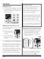
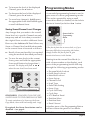
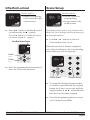
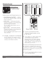
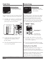
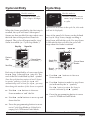
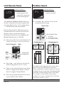
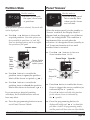
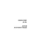
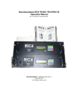
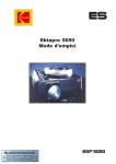
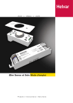
Programming & User Guide
Ambience 24 Master Panel
HES91240, HES91250, HES91270
Note: These illustrations show panels fitted with fascia plates.
Display Panel
Scene Recall
Buttons
(& Infra-Red Sensor)
1
2
3
1
5
2
6
3
7
4
8
s HES91240
t HES91270
1
5
9
13
2
6
10
14
3
7
11
15
4
8
12
16
HES91250
Control Buttons
Introduction
The Ambience 24 range of Master Panels
provide control of up to 24 lighting
Channels using up to 16 programmable
Scenes.
Three versions are available, each offering a
different number of Scene recall buttons:
• HES91240
• HES91250
• HES91270
4
4-button Panel
8-button Panel
16-button Panel
The user-definable Scenes can be recalled by:
• The Scene recall buttons which can be
assigned to any of the 16 Scenes.
• The built-in Scene ‘cycling’ function.
• Remote panels (available separately).
• Infra-Red handset (available separately).
Document Ref. EPD02181 (11/08/97)
On 4-button and 8-button panels, 16 Scenes
can still be used; the Scenes which can’t be
recalled by the buttons can be recalled by
remote panels or by the cycling function.
Power-up Procedure
When the panel is powered-up, the display
will remain blank for 5 seconds, then briefly
show the firmware version (e.g. V2.0).
Care & Maintenance
There are no user-serviceable parts in the
Ambience 24 panel. Refer all servicing to an
authorised Helvar Electrosonic agent.
The front of the panel may be cleaned
occasionally by wiping carefully with a
damp cloth. Do not use excessive amounts
of water, abrasive cleaners, polish or
solvents — these may damage the panel.
ENGLISH
Part No. I382GB issue 2
page 1
User Mode
Recalling a Scene
+ To recall a Scene, briefly press one of the
Scene recall buttons. The button indicator
will light and the chosen Scene number will
appear on the display.
1
5
2
6
3
7
Press briefly to recall
the associated scene.
4
8
‘Modifying’ the Overall Scene Level
The overall light level of a Scene can be raised
or lowered as follows:
+ To raise the overall
Scene level, press the
^ button.
+ To lower the overall
Scene level, press the
v button.
+ To cancel any modification, briefly press
the appropriate Scene recall button again.
The amount of level change is indicated by
the bargraph on the left of the display, with
the centre position denoting ‘no change’.
Once the indicator bar reaches its maximum
or minimum position (denoting an increase
or decrease of 200%), any further level
change will be shown by the bar flashing.
Document Ref. EPD02181 (11/08/97)
page 2
TECHNICAL NOTE
The modifier (raise/lower) function operates by
increasing or decreasing the level of all
‘active’ Channels within the Scene (i.e.
those programmed with specific levels or set
to ‘Select’ status. Channels that are set to
‘Ignore’ status are not affected.
Since a Channel cannot be ‘increased’ above
100% or ‘decreased’ below zero, the perceived
effect will depend on the starting level of the
Channels within the Scene. For example,
Scenes in which all Channels are set to
100% will show no increase in overall level.
The limit of modification is reached when all
active Channels in the Scene have reached
100% (full) or zero level.
Changing the Level of Specific Channels
+ Press either the < or > buttons to scroll
through the Channels associated with
the current Scene. The level of each
Channel is approximately indicated by the
bargraph as follows:
Channel
No.
Channel Level
= 100% (full)
= 87.5 – 99%
= 75 – 87.5%
= 62.5 – 75%
= 50 – 62.5%
= 37.5 – 50%
= 25 – 37.5%
= 12.5 – 25%
= 1 – 12.5%
Note:
Any Channels
that are set to
ignore status
are not
displayed
Ch 8
none = 0% (off)
Choose Channel Adjust Level
Note that only active Channels are displayed.
If there are no active Channels in the current
Scene the display will show ‘ Ch--’.
ENGLISH
Part No. I382GB issue 2
+ To increase the level of the displayed
Channel, press the ^ button.
+ To decrease the level of the displayed
Channel, press the v button.
+ To cancel any change(s), briefly press
the appropriate Scene recall button again,
or recall a different Scene.
Programming Modes
A concealed programming button is used to
gain access to various programming modes.
This can be operated by using a small
screwdriver blade (or similar) via the hole in
the fascia located just below the > button.
Saving Scene/Channel Level Changes
Any changes that you make to the overall
Scene level or to specific Channels are only
temporary and are lost when you reselect
the original Scene or select a different Scene.
However, the Ambience 24 Panel allows any
Scene or Channel level modifications made
to the current Scene to be saved as follows:
+ Recall a Scene and modify it as required
using the methods described previously.
+ To save the new levels to the current
Scene, press and hold the appropriate
Scene recall button for longer than 1
second. The display will flash ‘ Mem!’
when the new levels have been saved.
Mem!
1
5
2
6
3
7
Press and hold for longer than 1 second
to store modified scene/channel levels.
4
8
REMEMBER: CHANGES CAN ONLY BE
SAVED BACK TO THE ORIGINAL SCENE!
To create variations of a Scene use the Scene
Copy Mode, then recall and modify each ‘copy’.
If required, the Scene Save feature can be
disabled —see page 4.
Document Ref. EPD02181 (11/08/97)
Access hole for
Programming
Button
If the fascia plate has no access hole, or if you
have any difficulty in operating the button,
simply remove the fascia plate to gain
unrestricted access to the button.
Starting from the normal User Mode (i.e.
with a Scene number on the display), each
press of the programming button will step
through the following programming modes:
•
•
•
•
•
•
•
•
•
•
•
•
•
•
Program Mode Lockout
Scene Save Lockout
Infra-Red Lockout
Scene Set-up
Channel Level
Load Type
Fade Time Setting
Scene Copy
Cycle List Entry
Cycle Stop
LCS Remote Panel
Partition Select
Partition State
Panel ‘Snooze’
A further press of the Programming Button
will now return the panel to User Mode.
ENGLISH
Part No. I382GB issue 2
page 3
Program Mode Lockout
Open
Use this mode to:
• disable or enable
access to the other
programming modes.
When the programming modes are enabled,
the display will show ‘Open’. When they
are disabled, the display will show ‘Lock’.
Programming modes are enabled or
disabled by entering a security code (9120):
Scene Save Lockout
Mem-
Use this mode to:
• disable or enable the
ability to save
‘modified’ Scenes
(see page 3).
+ Press the v button to disable modified
Scene levels from being saved
(as indicated by the ‘-’ symbol).
Press the ^ button to re-enable this feature
(as indicated by the ‘+’ symbol).
Scene Save Status
+ Press any of the four control buttons to
prepare the display for code entry
(indicated by four dashes ‘----’).
Mem+
Security Access Code
Enable
( +)
----
Set Value
Disable
( -)
Move to next
or previous
digit
+ Press the programming button again to
move on to Infra-Red Lockout mode.
+ Press the ^ and v buttons to set the
value of the first digit.
+ Press the > button to move on to the
next digit, then set its value with the ^
and v buttons, and so on.
+ When the number is correct, press the
programming button to toggle from
enabled to disabled, and vice versa.
+ Press the programming button to move
on to Scene Save Lockout mode (if the
display shows ‘Open’) or back to User
Mode (if the display shows ‘Lock’).
Document Ref. EPD02181 (11/08/97)
page 4
ENGLISH
Part No. I382GB issue 2
Infra-Red Lockout
IR +
Scene Set-up
Use this mode to:
• disable or enable the
built-in Infra-Red (IR)
control sensor.
+ Press the v button to disable IR control
(as indicated by the ‘-’ symbol).
Press the ^ button to re-enable IR control
(as indicated by the ‘+’ symbol).
Infra-Red Sensor Status
IR +
Use this mode to:
• choose a Scene for
programming,
• assign Scenes to the
recall buttons.
The display for this mode is very similar to User
Mode, but can be distinguished by the absence of
the bargraph indicator.
+ Use the < or > buttons to choose a
Scene number from 1 to 16.
If the chosen Scene is already assigned to
one of the recall buttons, the corresponding
button indicator will now light-up.
Enable
( +)
Disable
( -)
1
5
2
6
3
7
4
8
+ Press the programming button again to
move on to Scene Set-up mode.
Choose Scene
Assign to Button
+ To assign the displayed Scene number
to a button, press and hold the required
button for at least one second, until the
display flashes ‘ Asn!’ which indicates
that the Scene has been assigned.
+ Press the programming button to move
on to Channel Level Mode.
Document Ref. EPD02181 (11/08/97)
ENGLISH
Part No. I382GB issue 2
page 5
Channel Level
Channel Level / Select / Ignore Status
= 100% (full)
= 87.5 – 99%
= 75 – 87.5%
= 62.5 – 75%
= 50 – 62.5%
= 37.5 – 50%
= 25 – 37.5%
= 12.5 – 25%
= 1 – 12.5%
Use this mode to:
• program Channel
levels for a Scene.
‘Select’ status
is indicated by
the following
pattern:
‘Ignore’ status
is indicated by
the following
pattern:
none = 0% (off)
Within a Scene, each Channel can be set to:
Scene Channel
No.
No.
• a level between 0 and 100% — which is
the level the Channel will go to when the
Scene is executed.
• select status — which means that the
Channel will remain at its existing level
when the Scene is executed.
This level will be affected by the ‘raise’ or
‘lower’ functions.
• ignore status — which means that the
Channel will remain at its existing level
when the Scene is executed.
The level will not be affected by the ‘raise’ or
‘lower’ functions.
+ Use the < or > buttons to scroll through
the 24 Channels. The bargraph indicates
the approximate level (or ‘Select’ or ‘Ignore’
status) for each Channel as follows:
Choose Channel
Set Level
+ To raise or lower the level of the
displayed Channel number, use the
^ or v buttons.
+ To set ‘Ignore’ or ‘Select’ status, press
and hold the v button until the
bargraph shows the ‘Ignore’ pattern.
Press the ^ button once to obtain the
‘Select’ pattern. A further single press of
the ^ button sets zero level.
The levels of all Channels in the Scene may
be examined or changed in the same way.
To program the levels for another Scene, briefly
press any Scene recall button to return the panel
to Scene Set-up Mode.
+ Press the programming button to move
on to Load Type Mode.
Document Ref. EPD02181 (11/08/97)
page 6
ENGLISH
Part No. I382GB issue 2
Load Type/Minimum Level
Use this mode to:
• define the load types
connected to each of
the 24 Channels and
their minimum level.
When entering this mode, there is a slight pause;
the display will then show ‘ Wait’ whilst the
panel accesses its load data table. During the
pause it is possible to reset the panel to its
factory default settings (see page 12).
Load Type / Minimum Level
Using Output Modules:
Using Dimmer Modules:
Switched (non-dim)
Switched (non-dim)
3.5–10V analogue
EL-FD with start pulse
DSI control
0–10V analogue
}}
} }Cold Cathode
} }Incandescent (tungsten)
Any bar lit within a block selects that load type (highest has
priority). The position within a block sets the minimum level.
Channel
No.
WARNING: Selecting this mode turns-on
all Channels to their current minimum level.
+ Use the < or > buttons to scroll through
the 24 Channels. The bargraph indicates
the load type/minimum level for each
Channel as follows:
Choose Channel
Set Load/Min.Level
+ Use the ^ or v buttons to move the
bargraph into the correct load type
‘block’ (as shown above), then adjust the
level within that block to the point
where the Channel just turns-on.
+ Press the programming button to move
on to Fade Time Mode.
Document Ref. EPD02181 (11/08/97)
ENGLISH
Part No. I382GB issue 2
page 7
Fade Time
Scene Copy
Use this mode to:
• set the fade time for
each of the 16 Scenes.
When this mode is selected, the display will show
‘ Wait’ whilst the panel accesses its fade data .
+ Use the < or > buttons to scroll through
the 16 Scenes. The bargraph indicates the
fade time for each Scene as follows:
Scene
No.
Cp 5
Use this mode to:
• copy the levels and
fade time of one Scene
into another.
The ‘source’ Scene (i.e. the Scene to be copied
from) will default to the one last chosen by
the Scene Set-up Mode. If this is not the
Scene you require, return to Scene Set-up
Mode and choose the correct Scene number
(see ‘Aborting Scene Copy Mode’ below).
Destination
Scene No.
Source
Scene No.
Scene Fade Time
= 60 seconds
= 40 seconds
= 20 seconds
= 10 seconds
= 8 seconds
= 6 seconds
= 4 seconds
= 2 seconds
= 1 second
10 5
Choose Destination
Scene Number
Choose Scene
Copy Scene and
move to next mode
Set Time
+ To alter the fade time setting for the
displayed Scene number, use the
^ or v buttons.
+ Press the programming button to move
on to Scene Copy Mode.
+ Use the < or > buttons to choose the
‘destination’ Scene (i.e. where the source
Scene will be copied to).
+ Press the programming button to copy
the Scene and move on to Cycle List Mode.
Aborting Scene Copy Mode
Whilst the ‘destination’ Scene is set to ‘ CP’
you can safely abort Scene Copy Mode
simply by pressing the programming button.
Otherwise, set the ‘destination’ Scene to match
the ‘source’ Scene (i.e. copy the Scene to
itself), then press the programming button.
Document Ref. EPD02181 (11/08/97)
page 8
ENGLISH
Part No. I382GB issue 2
Cycle List Entry
La ^
Cycle Stop
Use this mode to:
• create a Scene cycle
list of up to 16 steps.
When the Scene specified by the first step is
recalled, the cycle will start. Subsequent
Scenes are then recalled (in step order) once
the fade time of the previous Scene has
elapsed. The cycle will repeat until a ‘stop’
Scene is recalled (see ‘Cycle Stop Mode’).
Step No.
Scene No.
S- 1
Use this mode to:
• select/deselect one or
more ‘stop’ Scenes for
a cycle.
(If there are no Scenes in the cycle list, this mode
will not be displayed.)
Any of the panel’s 16 Scenes can be defined
as a cycle ‘stop’ Scene; simply recalling a
stop Scene will halt the cycle. If a stop Scene
is included in the cycle list, the cycle will
stop when this Scene is reached.
Stop Status
La14
Previous
Step
Scene No.
S+16
Choose Scene
or List End ( ^)
Create Stop
Scene ( +)
Choose Scene
Number
Next Step
Normal
Scene ( -)
Each step is identified by a lower-case letter
from a (step 1) through to p (step 16). The
end of the list is indicated by the ^ symbol.
Since the cycle function requires at least 2 Scenes
to operate, entering a Scene for step a will
automatically enter a Scene for step b; you may
then change the number of this Scene as required.
+ Use the < or > buttons to choose a
Scene number or ‘end’ the list.
+ Use the ^ and v buttons to move up and
+ Use the < or > buttons to choose a
Scene number.
+ Use the ^ button to make it a stop Scene
(as indicated by the ‘+’ symbol).
Use the v button to return the Scene to
normal (indicated by the ‘-’ symbol).
+ Press the programming button to move
on to LCS Remote Panel Mode.
down the list.
+ Press the programming button to move
on to Cycle Stop Mode or (if the list is
empty) to LCS Remote Panel Mode.
Document Ref. EPD02181 (11/08/97)
ENGLISH
Part No. I382GB issue 2
page 9
LCS Remote Panel
Use this mode to:
• define how LCS
remote panels will
control the operation
of the master panel.
The Ambience 24 Master Panel offers two
modes of operation for remote panels that
are using Panel A, B, C or D configuration
— Channel Mode and Scene Mode.
Pt -
+ Use the < or > buttons to choose the
required partition type.
Partition Type
Pt 1
Each mode provides a different range of
Channel and Scene control functions; full
details of these can be found in the
Installation Instructions for Ambience 24
Remote Panels (part no. I381GB).
Choose Partition Type
- = No Partition
1 = One Partition (2 areas)
4 = Four Partitions (4 areas)
+ Press any of the four control buttons; the
display will change to show the following:
Partition ab
Choose Panel
Configuration
+ Press the < or > buttons to choose the
Panel configuration (A, B, C or D).
+ Then, for the selected Panel, press the ^
button to apply Scene Mode, or the v
button to apply Channel Mode.
+ Press the programming button to move
on to Partition Select Mode.
Document Ref. EPD02181 (11/08/97)
Area
A
B
1
9
2
10
3
11
4
12
5
13
6
14
7
15
8
16
Area
A
Area
B
Area
D
Area
C
Partition bc
Area
B
Partition ad
Area
A
Channel
Mode
( Ch)
page 10
4-Partition System
Partition ab
Mode
A:Ch
Scene
Mode
( Sn)
1-Partition System
Scenes
Panel Configuration
Use this mode to:
• select/deselect a
partition system.
Partition cd
Scenes
LCS
Partition Select
A
1
2
3
4
Area
C
B
9
5
10
6
11
7
12
8
D
13
14
15
16
The tables in the diagram above show how
the 16 Scenes are allocated to each area.
When a partition is open between two areas,
recalling a Scene in one area will automatically
recall the corresponding Scene in the other.
For example, in a 4-partition system when
partition ‘bc’ is open, recalling Scene 5 will also
recall Scene 9 and vice versa.
ENGLISH
Part No. I382GB issue 2
Partition State
P:ab
Panel ‘Snooze’
Use this mode to:
• monitor or override
the open/closed state
of partitions.
(If no partition system is selected, this mode will
not be displayed.)
+ Use the < or > buttons to choose the
required partition. Note that options are
also provided for partitions ‘ac’ and ‘bd’;
these are dummy options and do not affect
the operation of the panel.
Partition Status
When the master panel is in the standby or
‘Snooze’ condition, the Display Panel is
dimmed and any bargraph or recall button
LED’s are extinguished. This condition is
implemented five seconds after the
execution of a designated Scene (usually an
‘off’ Scene) and remains in force until
another Scene is executed.
+ Use the < or > buttons to choose a
P:AB
Select
Open
( AB)
Z- 1
Use this mode to:
• put the master panel
into a standby state
when specific Scenes
are executed.
Scene number from 1 to 16.
Snooze Status
Scene No.
Choose Partition
(only applicable to
4-partition systems)
Select
Closed
( ab)
+ Use the ^ button to override the
partition status to open (the partition
label will be shown in capitals, e.g. AB).
+ Use the v button to override the
partition status to closed (the partition
label will be shown in lowercase, e.g. ab).
If you are using a physical partition
switch(es), the override buttons will not
have any effect.
+ Press the programming button to move
on to Panel ‘Snooze’ Mode.
Document Ref. EPD02181 (11/08/97)
Z- 8
Snooze On
( +)
Choose
Scene
Snooze Off
( -)
+ Press the ^ button to enable the chosen
Scene to trigger the snooze condition (as
indicated by the ‘+’ symbol).
Press the v button to disable this function
for the chosen Scene (as indicated by
the ‘-’ symbol).
+ Press the programming button; the
display will briefly read ‘End’ to show that
you have ‘visited’ all programming modes,
and the panel will then return to User Mode.
ENGLISH
Part No. I382GB issue 2
page 11
Resetting the Panel
If required, the panel can be returned to
these settings with the following procedure:
The Ambience 24 master panel is supplied
with the following default configuration:
+ Use the programming button to select
•
•
•
•
•
•
•
•
•
•
Program Modes enabled.
Scene Save
enabled.
Infra-Red Sensor enabled.
Scene 1
all Channels at 100%.
Scene 2
all Channels at 75%.
Scene 3
all Channels at 50%.
Scene 4
all Channels at 25%.
Scene 5 to 8
all Channels at 0%.
Scene 9 to 16
all Channels ‘ignored’.
Button/Scene Assignment:
HES91270
9
HES91250
Load Type Mode.
+ Before the display changes to show
‘ Wait’, press all four control buttons
simultaneously.
The panel will then automatically reset and
perform its ‘power-up procedure’ as
described on page 1.
HES91240
1
1
5
1
5
5
2
2 10 6
2
6
6
3
3 11 7
3
7
7
4
4 12 8
4
8
8
• Fade Times
• Load Types
•
•
•
•
•
all Scenes set to 2 seconds.
all Channels set to incandescent
at lowest turn-on level.
Cycle List
empty.
Stop Scenes none.
LCS Panels
all set to Channel Mode.
Partitions
none (all closed).
Snooze Mode disabled on all Scenes.
© 1997 HELVAR ELECTROSONIC Group
Hawley Mill, Hawley Road, Dartford, Kent. DA2 7SY (U.K.)
Tel: 01322 222211 Fax: 01322 282282
page 12
Part No. I382GB
Document Ref. EPD02181
issue 2 (11/08/97)