1
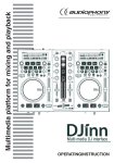
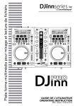
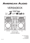
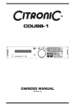
OWNERS MANUAL
Version 1.0
Safety information
1.
2.
3.
4.
5.
6.
7.
8.
9.
10.
11.
12.
13.
14.
15.
16.
Read these instructions.
Keep these instructions.
Heed all warnings.
Follow all instructions.
Do not use this item near moisture.
Clean only with dry cloth.
Do not block any of the ventilation openings. Install in accordance with the
manufacture’s instructions.
Do not install near any heat sources such as radiators, stoves or other items (including
amplifiers) that produce heat.
Do not defeat the safety purpose of the polarized plug. The wide blade is provided for
your safety. If the provided plug does not fit into the item or the mains socket, consult
an electrician for replacement.
Protect the power cord from being walked on or pinched particularly at plug, convenience
receptacles, and point where they exit from the item.
Only use attachments/accessories specified by the manufacturer.
Use only with a stand, tripod, bracket or table suitable for support.
Unplug this item during lightning storms or when unused for long periods of time.
Refer all servicing to qualified service personnel. Servicing is required when the item has
been damaged in any way, such as power supply cord or plug is damaged, liquid has
been spilled or objects have fallen onto the item, the item has been exposed to rain or
moisture, does not operate normally, or has been dropped (Note: Accidental or cosmetic
damage is not covered by the items 12 month warranty)
Please keep the unit in a safe environment.
Do not store anything on top of the item
DO NOT OPEN
RISK OF ELECTRIC SHOCK
CAUTION: To reduce the risk of electric shock, do not
remove any cover. No user-serviceable parts inside. Refer
servicing to qualified service personnel only.
The lightning flash with arrowhead symbol within the equilateral triangle is intended to
alert the use to the presence of un-insulated “dangerous voltage” within the product’s
enclosure that may be of sufficient magnitude to constitute a risk of electric shock.
The exclamation point within the equilateral triangle is intended to alert the user to the
presence of important operation and maintenance (servicing) instructions in the
literature accompanying this appliance.
Page 2 of 26
CITRONIC MP-X10
Main features:
1 x USB front and 1 x USB rear inputs which can be read by both players simultaneously
2 x Large VFD displays which can be viewed from wide angles
Plays MP3 files from either USB on the front or rear ports on either side of the player
Easy-to-use folder and file search
MP3/WAV compatible (ID3 tags)
Instant start (sound is produced immediately when the play button is pressed)
3 modes of operation (Vinyl, CD DJ and Auto cue scratch)
Interactive "AQ-touch" sensitive jog wheel
Jog wheel pitch bend ±100%
Pitch controlled ±6, 10 & 16/100%
Pitch lock function
Single and continuous play options
DSP effects: echo, flanger, filter, scratch and brake
X & Y Parameters controlled by jog wheel to maximize the sound effects
Seamless loop with fine tune adjustment
4 x Memory banks to store cue points or loops
3 band control with push button kill for each channel
Adjustable cross fader curve and cross fader reverse option
Fader start option
2 x external phono/Line Inputs
Microphone tone controls
Headphone monitoring with cue pan and volume controls
Memory backup, defaults to last setting
Auto/manual tap BPM
Relay playback
Part or full MIDI control by the PC
19" Rack mountable optional
Included accessories
1 x UK power cable
1 x EU power cable
1 x USB lead
1 x User manual
19” Rack mount kit
Page 3 of 26
Setup
1.
Before making or changing the connections, switch off the power and disconnect the
power cord from the AV outlet.
2.
We recommend to use high quality shielded audio cables when connecting input/output
devices as it makes a huge difference in sound reproduction quality.
3.
Do not use excessively long cables. Be sure the plugs and jacks are securely fastened.
Loose connections cause hum, noise or intermittence that can damage your speakers.
4.
Connecting to a computer – the controller will be automatically recognised by both
Windows based PC / Laptops operating Windows XP SP2 or later and MAC O/S 10.4 or
later as a generic MIDI controller without the need to install drivers (Note the DB
software only works with Windows based operating computers). You can then use any DJ
software with MIDI mapping features to program in the functions to operate on screen
(See Page 20)
Page 4 of 26
General Functions and Controls – Top panel
1.
VFD DISPLAY – This high quality VFD display indicates all the functions, as they are
occurring. The display icons are explained in the VFD display section (page 12)
2.
SEAMLESS LOOP:
a. IN – Pressing the IN button sets a CUE POINT without music interruption. This
button is also used to set the starting point of a SEAMLESS LOOP.
b. OUT - This button is used to set the ending point of a LOOP. A LOOP is started by
pressing the IN button to select the starting point and the OUT button to set the
LOOP ending point. The LOOP will continue to play until the OUT button is pressed
once again.
c. RELOOP – This button will highlight when a SEAMLESS loop has been made. Every
time you press this button it will return the music to the last set CUE point and
continue to play in a loop.
i. Pressing the RELOOP button will instantly reactivate the seamless loop
mode. To exit loop, press the OUT button. LOOP will appear in the LCD
display when the RELOOP function is available.
ii. You can fine tune the SEAMLESS LOOP by holding the RELOOP button and
using the jog wheel to set the exact OUT point. Press RELOOP again to set
the IN point. When you have finished press the RELOOP button to exit.
Page 5 of 26
3.
TRACK SEARCH – This knob has three functions:
a. You can use this to select the next or previous track by turning the knob forwards
or backwards.
b. Holding down and turning the knob forwards or backwards will rapidly skip through
the tracks on your USB memory device by 10 tracks per click.
c. Press the TRACK KNOB will read the ID3 tags on the file. Switch between: File
name / Title name / Artist / Bit rate on the LCD display.
4.
SAVE – This button has 3 functions in relation to the BANK BUTTONS (see PART 20)
a. Press this button to activate save mode. The SAVE button LED will glow when
active. When activated press your desired BANK button to store your CUE point or
playing SEAMLESS LOOP.
b. To store your CUE points or LOOPS that are in the BANK memory to your USB
device for use in the future press and hold the SAVE button for 2 seconds. The
SAVE button LED will flash to confirm it has saved.
c. RECALL MEMORY – The MP-X10 can store 4 programmed CUE point or LOOPS per
track on the USB device (The memory points on the USB are depending on
available memory space). These settings can be recalled at any time by first
pressing the SAVE button so it is highlighted. Then use the FOLDER and TRACK
knobs to search for the track you have the memory points stored. Once found the
VFD display will read “RECALLING” for a few seconds while it loads the memory in
to the desired bank. When ready for use the BANK buttons will be highlighted.
5.
X PARAMETER – (Time parameter) You can set the time parameter which effects the
sound produced by the digital effects by pressing the X button and rotating the JOG
WHEEL clockwise to increase the length of the effect or anti-clockwise to decrease the
level of the effect. Activate the HOLD button and rotate the JOG WHEEL to set the
default value. Note: For the above when the JOG WHEEL has stopped moving the ratio will return to the
default setting.
6.
SEARCH – These buttons allow you to fast forward or rewind the track when in PLAY or
CUE mode.
7.
JOG MODE – There are three modes of operation:
a. VINYL - When set to VINYL, touch the surface of the JOG WHEEL and rotate
clockwise or anti-clockwise to activate the scratch effect.
b. CD DJ - When set to CD DJ use the JOG WHEEL to bend the pitch of the track.
Clockwise to speed up the track anti-clockwise to slow down the speed of the track.
c. A.CUE SCRATCH
i. IN PLAYBACK MODE - While music is playing touch the JOG WHEEL to return
the track to last set CUE point and activate scratch mode (set by using the
IN button) hold down and move the JOG WHEEL clockwise and anticlockwise to use the scratch effect. When you release the track will continue
playing from the last set CUE point.
ii. IN CUE MODE - While the music is not playing (CUE mode), tapping the JOG
WHEEL will start the playback. Hold your finger on the JOG WHEEL to
continue playback. When your finger is released the music will stop and go
back to the last CUE point.
Page 6 of 26
8.
JOG WHEEL
a. The JOG WHEEL will act as a frame search control when the track in PAUSE or CUE
mode, allowing you to set a starting point or CUE point.
b. The JOG WHEEL also works as a pitch bend during playback. Turning the side of
the JOG WHEEL (in any JOG MODE) and turning clockwise will increase the pitch
percentage up to 100%, and turning the wheel counterclockwise will decrease the
pitch percentage down to -100%. The pitch bend will be determined by how long
you turn the JOG WHEEL continuously.
c. The JOG WHEEL can be used to control the TIME and RATIO parameters for the
digital effect.
9.
CUE PLAY – Press CUE PLAY button to return to the last set CUE point and continue
playing immediately. You can also tap the button continuously to create a BOP effect.
10.
CUE – Can be used in a number of ways:
a. Pressing the CUE button during playback immediately stops the current track and
returns the music to the last set CUE point.
b. In PAUSE mode pressing and holding the CUE button plays the track from the last
set CUE point. Releasing the CUE button will return the track to the last set CUE
point.
c. Pressing and holding CUE button will start the track. If PLAY/PAUSE button is
pressed during this time the track will continue to play when CUE button is
released
11.
PLAY/PAUSE – Pressing PLAY/PAUSE button will start the track instantly. Pressing this
button again will pause the current track.
12.
TAP - This button is used for manual BPM. When in manual BPM mode, tap this button to
the beat of the music Readout will be displayed on the VFD display. Hold the TAP button
for 1 second to activate AUTO BPM.
13.
PITCH BEND - The desired pitch of track increases when button “+” is held and
decreases when button “-” is held. The music returns to the original pitch when either
button is released.
14.
PITCH SLIDER - This slider is used to adjust the playback pitch percentage. Move the
slider down to speed up the music and move the slider up to slow down the music.
15.
KEY LOCK - This button turns on or turns off the KEY LOCK function. This function
allows you to use the PITCH SLIDER to speed up or slow down playback speed without
altering the tonal pitch of the track.
16.
TEMPO RANGE - Press the button to choose pitch percentage adjustment ±6%, ±10%,
±16%, and ±100%.
17.
PITCH ON/OFF – Press this button to turn the PITCH SLIDER ON/OFF.
18.
SOURCE SELECT - Use this button to read from USB PORT 1 or USB PORT 2.
19.
FOLDER SEARCH- Turn FOLDER knob to search for the desired folder.
20.
MEMORY BANKS 1~4 - These buttons are used to store either four CUE points or four
SEAMLESS LOOPS. Press the desired bank button to set a CUE point (Highlight RED) or
make a loop using the IN/OUT buttons and save to your desired bank button
(Highlighted GREEN). To delete any CUE points or LOOPS from the memory press CLEAR
followed by the BANK BUTTON you which to delete (For more information go to PART 4
“SAVE BUTTON”)
Page 7 of 26
21.
EFFECTS AND HOLD
a. EFFECTS - The below buttons add effects to the music. The volume and length of
the effects can be controlled by a combination of the PARAMETER BUTTONS and
JOG WHEEL.
i. ECHO – This button is used to add an ECHO effect your output signal.
ii. FLANGER – The FLANGER effect distorts the output signal and creates an
effect similar to the frequency phasing in and out of each other.
iii. FILTER – The FILTER effect tweaks the original sound to add different tonal
definition.
iv. BRAKE – The BRAKE effect is the both the start speed and stop speed of
the track simulating that of a turntable. The START time is controlled by the
X Parameter and the STOP time is controlled by the Y Parameter.
Depending on which operating mode the player is in determines how the
effect is triggered:
1. When in VINYL mode hold the top of the JOG WHEEL (Note: It is advised
to hold the side of the JOG WHEEL with one hand while doing this as any movement
from the JOG WHEEL at this point will cause the unit to go in to scratch mode)
2. When in CD DJ mode press PLAY/PAUSE button to activate.
b. HOLD – Activating the HOLD button in combination with one of the above TIME or
RATIO buttons allows you to lock the default level of either parameter. When the
desired level is set, deactivate the hold button for continued normal use.
22.
CLEAR – Press CLEAR button (LED on) or hold the CLEAR button to select the BANK
buttons you would like to clear.
23.
Y PARAMETER – (RATIO parameter) You can set the ratio parameter by selecting this
button and rotating the JOG WHEEL clockwise to increase the level of the effect or anticlockwise to decrease the level of the effect Note: For the above when the JOG WHEEL has stopped
moving the ratio will return to the default setting.
24.
TIME - The button will switch the time value described in the TIME METER between
ELAPSED playing time, TRACK remaining time and TOTAL remaining time.
25.
SGL/CTN - This function allows you to choose between single track play or continuous
track play (all tracks in order with no delay between tracks). This function also operates
in RELAY mode. With this button you can also switch auto cue on and off, by holding the
button down for 1 second.
Page 8 of 26
General Functions and Controls – Front Panel
1.
MIC 1 JACK – This jack socket is used to connect a microphone to the mixer. Connect
your microphone via 6.3mm jack. The volume output level for microphone will be
controlled by its own respective VOLUME control.
2.
MIC LEVEL CONTROL – These rotary knobs controls the output volume of
MICROPHONE 1 & 2. However master volume is controlled by the MASTER VOLUME
CONTROL on the mixer.
3.
MIC TONE CONTROL – This rotary knob control the frequency response of the
Microphone.
4.
MIC ON/OFF/TALKOVER SWITCH – When switched left the MIC is off, middle is ON
and to the right is TALKOVER position where the sound level for everything other than
that from the MIC will decrease to around 20dB.
5.
CUE PAN CONTROL – This slider allows you to monitor a cued track as well as the
current playing track from your headphones. When you move the CUE PAN to the left
position you will only hear the Channel 1 signal playing. If you move the CUE PAN to the
right you will only hear the Channel 2 signal playing. If the CUE PAN is set to the centre
position you can hear both Channels playing.
6.
CUE LEVEL CONTROL – This rotary knob is used to adjust the headphone volume. Turn
the knob in a clockwise direction to increase the headphone volume and anti clockwise to
decrease.
7.
HEADPHONE SOCKET – This jack socket is used to connect your headphones to the
device allowing you to monitor the cue channel. Always be sure the CUE LEVEL VOLUME
is set to minimum before you plugging in the headphones.
Page 9 of 26
General Functions and Controls – Mixer Panel
1.
USB PORT 1 - This is the USB port where you
insert your USB 2.0 mass storage device (up to
32Gb)
2.
MASTER VOLUME CONTROL – This rotary knob
is used to control the master output level
(volume). To avoid distorted output try to
maintain an average output signal level +4 dB.
NOTE: Be sure this volume control is always set to zero
before turning the unit on.
3.
BOOTH CONTROL – This rotary knob is used to
adjust the level of the BOOTH outputs.
4.
RELAY– This button is used to switch the RELAY
on and off. The left and right players will
automatically be in single play mode when the
relay function is activated. On the contrary, the
left and right players will automatically be in the
continuous play mode.
5.
MASTER METER – This button is used to choose
either master level or the individual channel level
on the CHANNEL LEVEL display indicators
6.
CHANNEL FADER – These faders are used to control the output signal of any source
assigned to its particular channel. However, master volume is controlled independently
by the MASTER VOLUME CONTROL.
7.
FADER START – These ON/OFF switches activate the FADER START function for each
channel. When activated the CROSSFADER can be used to stop and start a track
automatically. EG: If the CROSSFADER is in position CH1, the CH2 cued track will
automatically start playing. If the CROSSFADER is then moved back to CH1, CH2 will
stop playing and go back to the last cued point.
8.
CROSSFADER – This fader is used to blend the output signals of CHANNELS 1 and 2
together. When the fader is in the full left position, the output signal of CHANNEL 1 will
be controlled by the master volume level. The same fundamentals will apply for
CHANNEL 2. Sliding the fader from one position to another will vary the output signals of
channels 1 and 2 respectively. When the CROSSFADER is set in the centre position, the
output signals of both the CHANNEL 1 and CHANNEL 2 will be even.
9.
CF CURVE – Allows you to adjust the “shape” of the CROSSFADER response from a
gentle curve for smooth long running fades, to the steep pitch required for top
performance cut and scratch effects.
10.
LEVEL METER – The dual LED’s indicators are used to detail either the master output
level, a combination of the master output level or the PGM monaural level.
11.
CHANNEL EQ CONTROL – Both of the channels include a three-band signal EQ. These
controls are used to increase or decrease the HI, MID or LOW frequencies by turning the
desired knob from left to right. You can adjust the signal output between -30dB and
+10dB. You can also activate the KILL EQ by pressing either the HI, MID or LOW knobs
to reduce the frequency to the lowest level “-30dB”. A red LED will indicate that KILL
mode is active.
Page 10 of 26
12.
CHANNEL GAIN CONTROL – This adjustment is used to adjust an audio signal input
gain for a channel. Never use the gain control to adjust output volume. Set the gain level
properly will ensure a clean output signal.
13.
SOURCE SELECTOR – These switches are used to select the input source assigned to
each channel. Each channel may only be assigned one input source at a time.
a. CH1 & CH2 both set to PC – the entire unit works as a MIDI controller.
b. CH1 set to PC & CH2 set to DECK B – DECK A works as a MIDI controller and the
mixer works internally with DECK B.
c. CH1 set to PC & CH2 selected to L2/P2 – DECK A works as a MIDI controller and
the mixer works internally with L2/P2.
General Functions and Controls – Rear Panel
1.
POWER INLET (AC IN) – Use the provided IEC power lead to connect to an AC power
source.
2.
POWER SWITCH – Turn the unit power ON/OFF
3.
USB 2 PORT – This is the USB port where you insert your USB mass storage device for
playing MP3 files.
4.
USB MIDI PORT – Use the provided USB cable to connect the Citronic MP-X10 to a PC
or Laptop computer by a USB 2.0 connection. The computer will detect it straight away
as an external sound card (No need to install any drivers). Once installed you may then
play music on your computer and it will play through MP-X10 through the MASTER
output or BOOTH output.
5.
BALANCED XLR MASTER OUTPUT JACKS – L & R 3-pin balanced XLR jacks send a
high current balanced output signal. These jacks should be used when connecting to an
amp or other audio equipment with a balanced input, or whenever you will be running a
signal line greater than 4.5m.
6.
UNBALANCED MASTER OUTPUT – The RCA jacks send a low current unbalanced
output signal. These jacks should only be used for shorter cable runs to signal
processors, looping to another mixer or when connecting to small powered speakers.
7.
BOOTH OUTPUT JACKS – RCA jacks to connect to your active booth monitors.
Page 11 of 26
8.
LINE/PHONO SELECTOR SWITCH – These switches are used to change the voltage
line levels of there respected LINE/PHONO RCA inputs jacks. When connecting turntables
that do not have a built-in pre-amp to these jacks be sure the corresponding switch is in
the PHONO” position, and when using line level input devices be sure the switch is in the
LINE position. NOTE: Always be sure main power is shut off before changing the position
of the Line Level Selector Switch.
9.
CHANNEL LINE/PHONO INPUT CONNECTORS – Connect turntables without a built-in
pre-amp to the PHONO input and other devices such as. CD players, Tape Decks, MP3
devices and other line level instruments must be connected to the LINE input. Ensure
that you switch the LINE/PHONO switch to select the input. The input level volume is
controlled by the channel GAIN control.
10.
GND (GROUND TERMINAL) – Be sure to connect turntable ground leads to either or
both of the two available ground terminals. This will reduce the humming and popping
noises associated with magnetic phono cartridges.
11.
MICROPHONE 2 JACK – This combo jack will accept a standard 6.3mm jack plug or
XLR 3-pin balanced male plug. The volume output level for microphone will be controlled
by its own respective VOLUME control on the front panel.
General Functions and Controls – Rear Panel
1.
PLAY INDICATOR - The play indicator will glow when the unit is in play mode.
2.
RELOOP INDICATOR - Appears when LOOP is engaged or ready to be engaged.
3.
SINGLE INDICATOR - This indicates that the track is in single play mode, the track will
play once and return to CUE mode. If the single indicator is not on, the unit is in
continuous mode.
4.
FILE TYPE – Indicates if the music file is MP3, WAV or AAC
5.
TRACK DISPLAY - This indicator describes which track is currently cued or is playing.
6.
REMAIN / ELAPSED INDICATOR - When REMAIN is indicated in the VFD display the
TIME METER will show the current track's remaining time. When ELAPSED is indicated in
the VFD display the TIME METER will show the current track's elapsed time.
Page 12 of 26
7.
TIME METER - These indicators will detail the current minutes, seconds, and frames.
The meter will display either the elapse, total, or remaining time of a track or the entire
disc. The display time will depend on the selected time function. The selected time
function will be displayed above the TIME METER as total remaining, remaining track
time or elapsed track name.
8.
TIME BAR INDICATOR - This bar gives a visual approximation of a track or discs time.
This bar will begin to flash when a track is ending.
9.
PITCH INDICATOR - This meter will display the pitch percentage applied by the pitch
slider.
10.
TEMPO LOCK - This will indicate the TEMPO LOCK function is active.
11.
MEMORY BUCKET - This indicator serves two functions. The bucket symbol details the
cue memory status, a full bucket outline indicates the cue memory is full. The five bars
in the memory bucket detail the digital buffer. Each bar indicates 2 seconds. The search
functions will not operate until all the bars are full.
12.
BPM METER - This meter will display the BPM (beats per minute) of the current track.
Or the manual BPM that you set when you press the TAP button.
13.
BPM - This will indicate that the AUTO BPM counter is active.
14.
CHARACTER DISPLAY - This will display the name of the track and album when an MP3
track is loaded.
15.
FOLDER DISPLAY - This indicates which folder you are in.
16.
TOUCH INDICATOR - This appears when anything touches the JOG WHEEL.
17.
CUE INDICATOR - This indicator will glow when the unit is in CUE mode and will flash
every time a new CUE POINT is set.
18.
PAUSE INDICATOR - The pause indicator will glow when the unit is in pause mode.
Page 13 of 26
Internal Menu
Hold down the FOLDER knob for 2 seconds to enter the internal menu, and turn FOLDER knob to
search through the different menu.
Turn the TRACK knob or JOG WHEEL to change the submenus
Save and exit internal menu, turn the FOLDER knob to F. Exit & Save and press the TRACK knob.
The display indicates “Saving”
1. PLAYLIST - Normal / Title / Artist / Album/ Genre (for USB). Use the DBbuilder software
(see next section) in order to use the PLAYLIST type:
a. Normal: This is the default setting. Tracks are played corresponding to the
established hierarchical data structure
b. Title: Browse by the tracks by title name in alphabetical order
c. Artist: Browse by the tracks by artist name in alphabetical order
d. Album: Browse by the tracks by Album name in alphabetical order
e. Genre: Browse by the tracks by Genre type in alphabetical order
2. Repeat Mode – 3 different modes: Play All, REPEAT/FOLDER/TRACK
3. MIDI CH – Setup MIDI Channel from 1 to 16 (DECK A – MIXER – DECK B)
4. MIDI SETUP
a. TAP = HOLD/TOGGLE
b. I/O = Hide/DIS. (Hide/display MIDI I/O value)
5. Cross Fader
a. LOCK – Locks the CROSS FADER to the middle of the two channels
b. UNLOCK – CROSS FADER is active and can switch the MASTER OUTPUT from CH1
to CH2
6. Cross Fader Reverse
a. ON – Reverse the CROSS FADER
b. OFF – Normal operation
7. Display Time – 0.5 ~ 12.0 sec. (Line name start/stop time adjustment)
8. Scroll Speed – 50 ~ 2000 msec. (Line name move time adjustment)
9. Sensitivity -Touch wheel sensitivity adjustment (Adjustment range is -20~+20)
A. Intensity - VFD Brightness (Brightness range is 1~4)
B. A.CUE Level – Change the AUTO CUE level (Level range is -36~-78dB)
C. Bit Rate – Display ON/OFF
D. Version – CXX (Control version DSPXX (DSP version)
E. Load Default - Press TRACK Knob to enter load defaults.
F. EXIT & SAVE - Exit & Save setting to next power on (Press the TRACK knob to fast exit &
save in any operating mode)
Note:
Save: U1/U2, PITCH ON/OFF, PITCH RANGE, SGL/CTN, AUTO CUE, TIME MODE, HOLD, KEY
LOCK,
EFFECTS ON/OFF, PLAYLIST, REPEAT MODE, MIDI CHANNEL, MIDI SETUP, CROSSFADER,
CROSSFADER REVERSE, DISPLAY TIME, SCROLL SPEED, SENITIVITY, INTENSITY, A.CUE LEVEL,
DISPLAY
Defaults: U1/U2(U1), PITCH (OFF), PITCH RANGE (10%), SGL/CTN(CTN), AUTO CUE(ON), TIME
MODE
(REMAIN), HOLD(OFF), KEY LOCK(OFF), EFFECTS(OFF), PLAYLIST (NORMAL), REPEAT
MODE(ALL),
MIDI CHANNEL(1-2-3), MIDI SETUP(TAP=HOLD, I/O=HIDE), CROSSFADER(UNLOCK),
CROSSFADER
REVERSE(Off), DISPLAY TIME(3ms), SCROLL SPEED(400ms), SENITIVITY(0), INTENSITY(4),
A.CUE
LEVEL(-48dB),Bit rate display(ON)
Page 14 of 26
Data Management
DATABASE BUILDER:
Database management software for the MP-X10 scans your USB device and writes contents files
making it easy for you to search by Title, Artist, Album or Genre.
Installation: Refer to the following figures for installing database management software on your
computer.
CPU: Intel Pentium 4, 1GHz processor or above, Intel Centrino Mobile Technology 1.6GHz
RAM: 512MB
DISC SPACE: 100mb needed
OS: Microsoft Windows XP SP3, Vista SP2 or Windows 7 (NOTE: Software is not MAC compatible
but controller is)
Download available at www.citronic.com
STEP 1: Click next >
STEP 2: Click next >
Page 15 of 26
STEP 3: Click Install
STEP 4: Processing
STEP 5: Click finish
Page 16 of 26
Scan and create: Refer to the following process for scanning and creating database. NOTE: For
Vista users please right click the icon and select “RUN AS ADMINISTRATOR”
STEP 1: Select the desired
storage device and click build
STEP 2: Processing
STEP 3: Complete
NOTE: Please re-create the database builder whenever you change the contents of your USB
device.
PLAYLIST OPERATION:
1.
2.
3.
Hold the FOLDER knob down for 3 seconds to enter the internal menu.
Rotate the FOLDER knob to find the PLAYLIST option.
Turn the Track knob to select “Normal/ Title/ Artist/ Album/ Genre” and press the TRACK
knob to confirm the selection
4.
The MP-X10 will then read the data files created and display your tracks in the order you
desire
Page 17 of 26
Specification:
1.
2.
GENERAL SECTION
PRODUCT:
POWER SOURCE:
POWER CONSUMPTION:
DIMENSIONS:
WEIGHT:
MP-X10 Dual USB MP3 Player + Digital Mixer
AC 100-240V, 60/50Hz
21 WATTS
420mm (W) X 298.8mm (D) X 89mm (H)
4.42kg
INPUT/OUTPUT IMPEDANCE & SENSITIVITY: (EQ FLAT, MAXIMUM GAIN,
LOAD=100KΩ)
a. INPUT IMPEDANCE AND REFERENCE INPUT LEVEL
LINE: 47K OHM /-14dBV (200mV) +/-0.1dB
PHONO: 47K OHM /-50dBV (3.16mV) +/-0.1dB
MIC: 10K OHM /-50dBV (3.16mV) +/-0.1dB
b. OUTPUT IMPEDANCE AND LEVEL
MASTER: 1K OHM /0dBV (1V) +/-3dB
MASTER BAL(load=600 ohm): 600 OHM /+4dBm (1.23V) +/-3dB (BETWEEN HOT
AND COLD)
BOOTH: 1K OHM /0dBV (1V) +/-3dB
PHONES (load=32 ohm) 33 OHM /0dBV (1V) +/-2d
3.
FREQUENCY RESPONSE: (EQ FLAT, MAXIMUM GAIN, LOAD=100KΩ
LINE: 20 - 20K Hz +/-2dB
PHONO: 20 - 20K Hz +2/-3dB (RIAA)
MIC: 20 - 20K Hz +2/-3dB
4.
THD + N: (EQ FLAT, MAXIMUM GAIN, w/20kHz LPF, A-WEIGHTED,
LOAD=100KΩ)
LINE: LESS THAN 0.06% @ 1 KHz
PHONO: LESS THAN 0.08% @ 1 KHz
MIC: LESS THAN 0.15% @ 1 KHz
5.
MAXIMUM INPUT: (1KHz, THD=1%, EQ FLAT, MAXIMUM GAIN, LOAD=100KΩ)
LINE: MORE THAN +0dBV
PHONO: MORE THAN -36dBV
MIC: MORE THAN -36dBV
6.
MAXIMUM OUTPUT: (1KHz, THD=1%, EQ FLAT, MAXIMUM GAIN, LOAD=100KΩ)
MASTER: MORE THAN +15dBV (5.62V) LOAD=100KΩ
PHONES: MORE THAN +4dBV (1.6V) LOAD=32Ω
7.
S/N RATIO: (MAXIMUM GAIN, EQ FLAT, W/20KHz LPF, A-WEIGHTED)
LINE: MORE THAN 73dB
PHONO: MOTE THAN 73dB
MIC: MORE THAN 63dB
8.
CROSSTALK: (MAXIMUM GAIN, EQ FLAT, W/20KHz LPF, A-WEIGHTED,
MASTER=0dBV OUTPUT)
LINE, PHONO: MORE THAN 63dB @1KHz BETWEEN L AND R CHANNEL
MORE THAN 70dB @1KHz BETWEEN CHANNELS
9.
FADER KILL: (MAXIMUM GAIN, EQ FLAT, W/20KHz LPF, A-WEIGHTED, MASTER
=0dBV OUTPUT)
CHANNEL FADER: MORE THAN 70dB AT 1KHz
CROSSFADER: MORE THAN 70dB AT 1KHz
Page 18 of 26
Cont.
10.
TONE, EQ
MIC:
CHANNEL:
-14 +/-3dB AT 100Hz
-12 +/-3dB AT 10 KHz
10 +/-2dB, BELOW -30dB AT 70Hz
10 +/-2dB, BELOW -30dB AT 1 KHz
10 +/-2dB, BELOW -30dB AT 13 KHz
11.
CHANNEL BALANCE
Within 2dB
12.
TALKOVER:
-20dB +/- 2dB
13.
USB HOST PLAYER: (SIGNAL FORMAT: MP3, 128KBPS)
a. OUTPUT LEVEL: 0dBV +/-2dB (TCD782 TRK16, GAIN MAXIMUM, EQ FLAT)
b. FREQUENCY RESPONSE: 17-16KHz +/-2dB (TCD781 TRK1,4,16, SET GAIN TO
0dBV OUT, EQ FLAT)
c. THD+N: LESS THAN 0.08% (TCD782 TRK16, GAIN MAXIMUM, EQ FLAT, W/20KHz
LPF, A-WEIGHTED)
d. SN RATIO: MORE THAN 70dB (TCD782 TRK2,8, SET GAIN TO 0dBV OUT, EQ FLAT,
W/20KHz LPF, A-WEIGHTED)
e. LR SEPARATION: MORE THAN 63dB AT 1KHz (TCD782 TRK2,9,11, SET GAIN TO
0dBV OUT, EQ FLAT, W/20KHz LPF, A-WEIGHTED)
14.
USB HOST PLAYER SECTION: (SIGNAL FORMAT: MP3, 128KBPS)
a. OUTPUT LEVEL: 0dBV +/-2dB (TCD782 TRK16, GAIN MAXIMUM, EQ FLAT)
b. FREQUENCY RESPONSE: 17-16KHz +/-2dB (TCD781 TRK1,4,16, SET GAIN TO
0dBV OUT, EQ FLAT)
c. THD+N: LESS THAN 0.08% (TCD782 TRK16, GAIN MAXIMUM, EQ FLAT, W/20KHz
LPF, A-WEIGHTED)
d. SN RATIO: MORE THAN 70dB (TCD782 TRK2,8, SET GAIN TO 0dBV OUT, EQ
FLAT, W/20KHz LPF, A-WEIGHTED)
e. LR SEPARATION: MORE THAN 63dB AT 1KHz (TCD782 TRK2,9,11, SET GAIN TO
0dBV OUT, EQ FLAT, W/20KHz LPF, A-WEIGHTED)
f. RECORING & PLAYBACK: (LINE 1KHz, -14dBV INPUT, GAIN MAXIMUM) OUTPUT:
6dBV (2V) +/-2dB THD+N: LESS THAN 0.08% (GAIN MAXIMUM, W/20KHz LPF, AWEIGHTED)
15.
MP3 FORMAT
USB
Format
MP3
Format
File System
FAT 12/16/32
Applicable file extensions
mp3. MP3. mP3. Mp3
Max. number of Folders
999
Max. number of files
max. 999 files
MPEG 1 Layer 3 standard (ISO/IEC
11172-3), which provides for single
channel (‘mono’) and two-channel
(‘stereo’) coding at sampling rates of
32, 44.1 and 48kHz.
32/40/48/56/80/96/112/128/160/192/224/256/320
kbps
MPEG 2 Layer 3 standard (ISO/IEC
13818-3), which provides for similar
coding at sampling rates of 16, 22.05
and 24 kHz.
32/40/48/56/64/80/96/112/144/160 Kbps
MPEG 2.5 Layer 3 standard, which
provides for similar coding at
sampling rates of 8, 11.025 and 12
kHz.
32/40/48/56/64/80/96/112/144/160 Kbps
Xing/VBRI VBR
Xing/VBRI VBR
Xing/VBRI VBR
Page 19 of 26
MIDI MAP
FUNCTION
Type
FUNCTION
CODE
(DECK A)
SW/ENC
05/17
SW/ENC
01/16
IN
SW/LED
02/02
OUT
SW/LED
03/03
SW/LED
04/04
SOURCE
SELECT/U1
SW/LED
06/06
SAVE
SW/LED
07/07
1
SW/LED (RED)
08/08
1
LED (GREEN)
2
SW/LED (RED)
2
LED (GREEN)
3
SW/LED
(RED)
3
LED (GREEN)
4
SW/LED (RED)
4
LED (GREEN)
CLEAR
SW/LED
0C/0C
SW/LED
0D/0D
SW/LED
0E/0E
30
09/09
NOT
E
44/56
40/55
D-1
41
D#1
42
E-1
43
F#1
45
G-1
46
G#1
47
C3
A-1
31
C#3
0A/0A
A#1
32
0B/0B
SHIFT
(Hold TAP)
48
02/02
03/03
04/04
06/06
07/07
08/08
09/09
0A/0A
32
4A
0B/0B
SHIFT
(Hold TAP)
44/66
40/65
01/26
31
49
NOTE
05/27
30
D3
B-1
FUNCTION
CODE (DECK B)
D-1
41
D#-1
42
E-1
43
F#-1
45
G-1
46
G#-1
47
C3
A-1
48
C#3
A#-1
49
D3
B-1
4A
D#3
Time X
33
D#
3
C0
33
4B
C#0
4C
D0
4D
0C/0C
0D/0D
0E/0E
C0
4B
C#0
4C
D0
4D
FUNCTION
CODE
(CENTER DECK)
NOTE
SHIFT
(Hold
TAP)
ACTION
:
:
7FH:ON 00H:OFF
7FH:ON 00H:OFF
7FH:ON 00H:OFF
7FH:ON 00H:OFF
7FH:ON 00H:OFF
7FH:ON 00H:OFF
7FH:ON 00H:OFF
7FH:ON 00H:OFF
7FH:ON 00H:OFF
7FH:ON 00H:OFF
7FH:ON 00H:OFF
7FH:ON 00H:OFF
7FH:ON 00H:OFF
7FH:ON 00H:OFF
7FH ON 00H OFF
:
:
7FH:ON 00H:OFF
7FH:ON 00H:OFF
7FH ON 00H OFF
ECHO
SW/LED
0F/0F
FLANGER
SW/LED
10/10
HOLD
SW/LED
11/11
FILTER
SW/LED
12/12
SKID
SW/LED
13/13
RATIO Y
SW/LED
14/14
%/ 16
SW/LED
15/15
SW
16
SW
17
A.Cue
scratch
SW/LED
18/18
VINYL
SW/LED
19/19
CDJ
SW/LED
1A/1A
Time
SW
1B
SGL/CTN
SW
1C
JOG
CUE
CUE
TAP
SW/LED
1D/1D
SW/ENC
27/18
SW
4E
E0
4F
F0
50
F#0
51
G0
52
G#
0
53
A0
54
55
56
C1
57
C#1
58
D1
59
5A
5B
F1
1F/1F
SW/LED
20/20
SW/LED
21/21
22
5C
66/57
5D
1E
SW/LED
SW
D#
0
G1
5E
G#
1
5F
A1
60
61
0F/0F
10/10
11/11
12/12
13/13
14/14
15/15
D#0
4E
E0
4F
F0
50
F#0
51
G0
52
G#0
53
A0
54
55
16
56
17
18/18
19/19
1A/1A
1B
C1
57
C#1
58
D1
59
D-1
5A
5B
1C
1D/1D
F1
66/67
27/28
5D
1E
1F/1F
20/20
21/21
22
5C
G1
5E
G#1
5F
A1
60
61
:
:
7FH:ON 00H:OFF
7FH:ON 00H:OFF
7FH:ON 00H:OFF
7FH:ON 00H:OFF
7FH:ON 00H:OFF
7FH:ON 00H:OFF
7FH:ON 00H:OFF
7FH:ON 00H:OFF
7FH:ON 00H:OFF
7FH:ON 00H:OFF
7FH:ON 00H:OFF
7FH:ON 00H:OFF
7FH:ON 00H:OFF
7FH:ON 00H:OFF
7FH:ON 00H:OFF
7FH:ON 00H:OFF
7FH:ON 00H:OFF
7FH:ON 00H:OFF
7FH:ON 00H:OFF
7FH:ON 00H:OFF
7FH ON 00H OFF
Page 21 of 26
SW
62
23
67
PITCH
BEND/28
:
:
7FH:ON 00H:OFF
62
23
7FH ON 00H OFF
67
Pitch Silder
VR/CENTER
GAIN
VR
HIGH
VR/SW/CENTER/LE
D
12/24/29/
24
C2
51/63/68
MID
VR/SW/CENTER/LE
D
13/25/2A/
25
C#2
52/64/69
LOW
VR/SW/CENTER/LE
D
14/26/2B/
26
D2
53/65/6A
Channel Fader
VR
10
U2
LED
2C
10
LED
2D
6
LED
2E
LEVEL
METER LED
LEVEL METER LED
1
RELAY
SW/LED
37/37
MASTER METER
SW/LED
38/38
MASTER
VR
BOOTH
VR
Cross Fader
VR/SW/
SW/CENTER
MIC1 LEVEL
VR
MIC2 LEVEL
VR
CUE PAN
SLIDER
VR
CUE PAN LEVEL
VR
50
11
4F
PITCH BEND/28
60
VR:00~7F
C2
61/63/68
VR:00~7F
C#2
62/64/69
VR:00~7F
D2
63/65/6A
VR:00~7F
5F
VR:00~7F
21
22/24/29/24
23/25/2A/25
24/26/2B/26
20
:
G#2
G#
2
A2
A#2
2D
2E
:
7FH ON 00H OFF
2C
A2
:
:
7FH:ON 00H:OFF
00H~7FH*
7FH:ON 00H:OFF
7FH:ON 00H:OFF
7FH ON 00H OFF
A#2
1
G3
76
G#3
77
31
70
VR:00~7F
32
71
VR:00~7F
30/08/
09/0A
VR:00~7F
35
6F/47
/48/4
9
74
36
75
VR:00~7F
34
73
VR:00~7F
33
72
VR:00~7F
VR:00~7F
Page 22 of 26
Fader Start
ON(L)
SW
Fader Start
OFF(L)
SW
Fader Start
ON(R)
SW
Fader Start
OFF(R)
SW
C.F CURVE
(L)
SW
C.F CURVE
(CENTER)
SW
C.F CURVE
(R)
SW
1
40
2
41
3
42
4
43
7
46
6
45
5
44
:
:
7FH:ON 00H:OFF
7FH:ON 00H:OFF
7FH:ON 00H:OFF
7FH:ON 00H:OFF
7FH:ON 00H:OFF
7FH:ON 00H:OFF
7FH ON 00H OFF
Page 23 of 26
CC-ABSOLUTE (VR, LEVEL METER LED) TYPE
Control Change messages are sent with status 0xBn, where n is the channel, for the specified CC
controller. Thus the controller MIDI ID is indicated with the channel along with the CC number.
The value from 0x00 to 0x7F, directly related to the location of the controller.
*
LEVEL METER LEDS
00~0B => ALL LEDS OFF
0C~17=>LED(-30) ON
18~23=>LED(-30, -20) ON
24~2F=>LED(-30, -20, -10) ON
30~3B=>LED(-30, -20, -10, -7) ON
3C~47=>LED(-30, -20, -10, -7, -4) ON
48~53=>LED(-30, -20, -10, -7, -4, -2) ON
54~5F=>LED(-30, -20, -10, -7, -4, -2, 0) ON
60~6B=>LED(-30, -20, -10, -7, -4, -2, 0, +2) ON
6C~77=>LED(-30, -20, -10, -7, -4, -2, 0, +2, +4) ON
78~7F=> ALL LEDS ON (-30, -20, -10, -7, -4, -2, 0, +2, +4, +7)
CC-RELATIVE (ENC)TYPE
Control Change messages are status 0xBn, where n is the channel, for the specified CC controller.
Thus the controller MIDI ID is indicated with the channel along with the CC number. The value
from 0x40 to indicate the change in the controller. This is an offset to 0x40 “one’s complement”
notation.
A message with data 0x43 indicates a positive change of 3.
A messages with data 0x31 indicates a negative change of 15.
SWITCH ON/OFF (SW,CENTER TYPE)
These messages are used for switches.
Control Change messages are sent with status 0x9n, SWITCH On and Off value are 0x7F and
0x00, where n is the channel.
LED ON/OFF (LED TYPE)
These messages are used for LED.
Control Change messages are sent with status 0x9n, LED On and Off value are 0x7F and 0x00,
where n is the channel.
Page 25 of 26
FOR MORE INFORMATION ON CITRONIC PRODUCTS VISIT
WWW.CITRONIC.COM
Copyright protected by Citronic UK