1
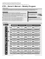
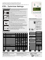
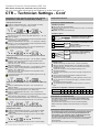
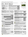
Systems Controls & Instruments (UK) Ltd.
Manx House, Bousley Rise, Ottershaw, Surrey, KT16 0JX
Tel / Fax: +44 (0)1 93287 5227 & 5225: E mail: [email protected], Web: www.sciuk.co.uk
CTR – Owner’s Manual
Normal Display
Real Time Clock
In normal display, the LCD alternates
between a Real Time Clock and Set &
Room Temperatures.
Real time
clock
Press the CLOCK button again – the minutes
will flash.
Using the (+) and (-) buttons adjust the minutes.
Set & Room
temperatures
Press the CLOCK button – the day will flash.
Using the (+) and (-) buttons adjust the day.
CLOCK
SUN
SET
Press the CLOCK button – the hours will flash.
Using the (+) and (-) buttons adjust the hours.
SUN
SUN
TEMP
HEAT
On/Off – Green LED
SUN
Temperature Set-Point
Press the ON/OFF button to turn the thermostat
ON/STBY
ON or OFF.
ALARM
When the thermostat is ON, the green LED
(ON/STBY) is turned ON.
The Green LED will flash during the 4 minutes compressor delay.
Mode
In COOL mode:
Press the (+) or (-) buttons – “SET" & set-point
temperature will flash.
Using the (+) or (-) buttons adjust the set-point
temperature for cool.
SET
TEMP
SET
TEMP
SET
TEMP
SET
TEMP
COOL
In HEAT mode:
Press the (+) or (-) buttons – “SET" & set-point
temperature will flash.
Using the (+) or (-) buttons adjust the set-point
temperature for heat.
Press the MODE button to switch between:
COOL
COOL
HEAT
HEAT
HEAT
HEAT
COOL
In AUTO CHANGE-OVER mode:
Press the (+) or (-) buttons – “COOL", “SET” & setpoint temperature will flash.
Using the (+) or (-) buttons adjust the setpoint temperature for cool.
AUTO CHANGE-OVER
The active mode will flash.
FAN ONLY
Wait a few seconds – “HEAT", “SET” & setpoint temperature will flash.
Using the (+) or (-) buttons adjust the setpoint temperature for heat.
Auto Fan
Press the AUTO FAN button to turn the AUTO FAN
function ON or OFF.
AUTO FAN
When the thermostat is working in AUTO CHANGE-OVER mode, it
has 2 different set-points, 1 for cool and 1 for heat. The thermostat
will automatically keep a safety differential of at least 1 degree
between the two set-points (heating set-point is always less than
cooling set-point).
AUTO FAN OFF
The fan will work continuously.
In Oil systems, in heating mode, switching the
AUTO FAN function ON will turn the fan OFF.
(The unit will work without the fan).
Economy Mode
In FAN ONLY mode:
The set-point temperature cannot be adjusted in FAN
ONLY mode. When pressing the (+) or (-) buttons, the
ambient temperature will be displayed.
Press the SELECT button to view the outdoor temp.
TEMP
The option is available only when an outdoor
temperature sensor is connected to the unit.
Reset / Alarm Conditions
When the ambient temperature rises or drops to a
pre-defined alarm limit set by the technician, the
red LED will flash and the alarm output will be
activated.
Press & Hold the RESET button (5 seconds) to
clear the alarm and call technician.
Turning economy mode OFF
Press & Hold the AUTO FAN button (5 seconds) –
until the thermostat returns to normal display.
In economy mode, none of the buttons work.
File: ctr-owners maual.vsd | Date: February 4, 2007 | Rev. 2
TEMP
View the Outdoor Temperature
When the thermostat is set to work in economy mode, it
overrides the set-point temperatures given by the user,
and uses pre-defined economy set-points.
Use the economy mode when leaving home/office for
vacation or when out of town.
Turning economy mode ON
Turn the thermostat ON
Press & Hold the AUTO FAN button (5 seconds) –
until “EC” appears on display.
HEAT
COOL
Use the AUTO CHANGE-OVER mode on days when both heating
and cooling are necessary.
AUTO FAN ON
The fan will work only when there is demand for
cooling or heating.
The AUTO FAN function is not available when the
thermostat is in FAN ONLY mode.
HEAT
COOL
Page 1/2
ON/STBY
ALARM
All rights reserved to SCI UK © 2007
Systems Controls & Instruments (UK) Ltd.
Manx House, Bousley Rise, Ottershaw, Surrey, KT16 0JX
Tel / Fax: +44 (0)1 93287 5227 & 5225: E mail: [email protected], Web: www.sciuk.co.uk
CTR – Owner’s Manual – Weekly Program
Weekly Program
The thermostat can be programmed with up to 12 different programs: Four different programs for the weekdays (Monday to Friday);
Four different programs for Saturday and four different programs for Sunday (The daily programs are numbered 1, 2, 3 & 4).
Activate / Deactivate the program
Setting the program
Press the PROG button to enter programming – all 4 digits will flash.
Use the CLOCK button here to quickly switch between Weekdays, Saturday & Sunday.
Press the PROG button again – “PROGRAM 1” & weekdays will appear. the hours will flash.
Use the CLOCK button here to quickly switch between Programs 1, 2, 3 & 4.
Using the (+) and (-) buttons adjust the START TIME - HOURS for PROGRAM 1 (weekdays).
Press the PROG button again - the minutes will flash
Using the (+) and (-) buttons adjust the START TIME - MINUTES for PROGRAM 1 (weekdays).
Press the PROG button again – “COOL” and set-point temperature will flash.
Using the (+) and (-) buttons adjust the SET-POINT TEMPERATURE FOR HEAT .
Press the PROG button again – “HEAT” and set-point temperature will flash.
Using the (+) and (-) buttons adjust the SET-POINT TEMPERATURE FOR COOL .
Press & Hold the PROG button to
activate / deactivate the program.
When the program is active, the
word “PROGRAM” and the clock
icon will appear on display,
PROGRAM
Override the program set-points
The user can temporarily change the set-point
temperature to be different than the set-point
temperature specified by the program. This change
will be affective until the next event of the program
begins.
Press the PROG button again to set PROGRAM 2 and repeat the procedure.
Program Chart
PROG
Enter
programming
Hours
PROG
PROG
CLOCK
PROG
PROG
PROG
PROG
CLOCK
PROG
PROG
PROG
PROG
PROG
PROG
Weekdays - Prog 1
(hours)
Weekdays - Prog 2
(hours)
Weekdays - Prog 3
(hours)
Weekdays - Prog 4
(hours)
Saturday - Prog 1
(hours)
Saturday - Prog 2
(hours)
Saturday - Prog 3
(hours)
Saturday - Prog 4
(hours)
Sunday - Prog 1
(hours)
Sunday - Prog 2
(hours)
Sunday - Prog 3
(hours)
Sunday - Prog 4
(hours)
File: ctr-owners maual.vsd | Date: February 4, 2007 | Rev. 2
Minutes
PROG
PROG
PROG
PROG
PROG
PROG
PROG
PROG
PROG
PROG
PROG
PROG
Weekdays - Prog 1
(minutes)
Weekdays - Prog 2
(minutes)
Weekdays - Prog 3
(minutes)
Weekdays - Prog 4
(minutes)
Saturday - Prog 1
(minutes)
Saturday - Prog 2
(minutes)
Saturday - Prog 3
(minutes)
Saturday - Prog 4
(minutes)
Sunday - Prog 1
(minutes)
Sunday - Prog 2
(minutes)
Sunday - Prog 3
(minutes)
Sunday - Prog 4
(minutes)
Page 2/2
Set-point temperature for cool
PROG
PROG
PROG
PROG
PROG
PROG
PROG
PROG
PROG
PROG
PROG
PROG
Weekdays - Prog 1
(set-point for heat)
Weekdays - Prog 2
(set-point for heat)
Weekdays - Prog 3
(set-point for heat)
Weekdays - Prog 4
(set-point for heat)
Saturday - Prog 1
(set-point for heat)
Saturday - Prog 2
(set-point for heat)
Saturday - Prog 3
(set-point for heat)
Saturday - Prog 4
(set-point for heat)
Sunday - Prog 1
(set-point for heat)
Sunday - Prog 2
(set-point for heat)
Sunday - Prog 3
(set-point for heat)
Sunday - Prog 4
(set-point for heat)
Set-point temperature for heat
PROG
PROG
PROG
PROG
PROG
PROG
PROG
PROG
PROG
PROG
PROG
PROG
Weekdays - Prog 1
(set-point for cool)
Weekdays - Prog 2
(set-point for cool)
Weekdays - Prog 3
(set-point for cool)
Weekdays - Prog 4
(set-point for cool)
Saturday - Prog 1
(set-point for cool)
Saturday - Prog 2
(set-point for cool)
Saturday - Prog 3
(set-point for cool)
Saturday - Prog 4
(set-point for cool)
Sunday - Prog 1
(set-point for cool)
Sunday - Prog 2
(set-point for cool)
Sunday - Prog 3
(set-point for cool)
Sunday - Prog 4
(set-point for cool)
All rights reserved to SCI UK © 2007
Systems Controls & Instruments (UK) Ltd.
Manx House, Bousley Rise, Ottershaw, Surrey, KT16 0JX
Tel / Fax: +44 (0)1 93287 5227 & 5225: E mail: [email protected], Web: www.sciuk.co.uk
CTR – Technician Settings
Installation Instructions
It is recommended to mount the thermostat between 1.5 & 1.8
meters from the floor where possible.
Separate the base from the cover by pressing the tongue (pic.1).
Spring tongue
Gently disconnect the quick connector between cover and base
(pic.2)
Spring tongue
Pic.1
Line the back panel up against the wall and drill the appropriate
fixing holes (pic.3).
Insert screws so they extend approx. 3/16" (3 mm) from the wall.
Align the back panel against these screws, pushing it forward,
allowing it to slide downwards to lock into position.
Quick connector
Make electrical connections to terminals on the back panel. Refer
to the “Wiring Connections” section.
Shafts
Jumpers Configuration
Reconnect the quick connector.
Pic.2
Change the JUMPERS position according to the system
configuration. Refer to the “Jumper Configuration” section.
Disconnect power,
remove battery and
wait 5 minutes* before
changing the jumpers
position.
JP7
JP6
JP5
JP4
JP3
Attach the cover to the base, first the two shafts and then the
spring.
Connect 24Vac to the thermostat; verify that LCD display is ON.
Do not install battery before power is applied.
Pic.3
Back panel
Front panel
+
A
JP1
B
Reassemble front and back cover.
Pic.4
Connect at top first then at bottom .
Wiring Connections
Function
HC11 HC22 HC32
HP11
HP22
HP32
Outdoor temperature sensor
OPT
OPT
OPT
OPT
OPT
OPT
T1,T1
External sensor (option)
OPT
OPT
OPT
OPT
OPT
OPT
AUX
Fault input from system
OPT
OPT
OPT
OPT
OPT
OPT
+
-
+
+
+
+
+
-
+
+
+
+
H.E 1
H.E 1
H.E 1
H.P
H.P
H.P
+
-
+
+
-
+
+
+
-
+
-
+
-
+
+
-
OPT
OPT
OPT
OPT
OPT
Y1
Compressor 1
Y2
Compressor 2
Heat Element 1 / Heat Pump
W2
Heat Element 2
W3
Heat Element 3
G1
Fan
G2
Not in use
AL,AL
Low & High temp. alarm (dry contact) OPT
Rc
24Vac Phase (red)
+
+
+
+
+
+
Rh
24Vac (jumpered to Rc terminal)
+
+
+
+
+
+
+
+
+
+
+
+
OPT
OPT
OPT
OPT
OPT
OPT
H.P
Heat
Pump
C
24Vac Common
14,15,16
+
Another IR Receiver (option)
Connect
-
Not
in use
JP1
Temperature Sensor
T0,T0
W1 (B/O)
Important: When
changing the jumpers
configuration, all
information stored in
the memory will be lost
including the weekly
program.
Be careful - the top clip of the battery holder is fragile.
Battery Holder
Terminal
*No need to wait if the
unit wasn’t connected
to power (1st Install).
Remove battery from back panel by sliding it to the left and out from
its white retaining clip and mount it in black holder on front panel;
insert it from the top, gently pressing downwards until it snaps into
place and is held under the top clip of the holder.
The '+' engraved on battery should be visible (pic. 4).
H.E 1
Heat
element 1
OPT
Option
Internal sensor
A Position
External sensor
B Position
JP3
Compressor Delay
4 minutes delay
OPEN
No delay (for test only !)
SHORT
JP4
Clock Mode
24 Hours
OPEN
12 Hours (AM/PM)
SHORT
JP5
Temperature Scale
Fahrenheit
SHORT
Celsius
OPEN
HC / HP Configuration
HC Electric
HC Oil/Gas
JP6
JP7
OPEN
OPEN
OPEN
SHORT
HP energized in COOL
SHORT
OPEN
HP energized in HEAT
SHORT
SHORT
Default from
factory
Jumper
SHORT
Jumper
OPEN
Replace Battery
Follow these steps to replace the battery:
Disconnect power.
Remove existing battery.
Leave thermostat disconnected for 15 minutes.
File: ctr-technician settings.vsd | Date: February 01, 2007 | Rev. 2
Connect power (without the battery).
Check if the unit works.
Gently place the new battery into the holder.
Test the memory of the thermostat.
Page 1/2
Low battery
indication
Use only lithium cell 3v
battery – CR2032
All rights reserved to SCI UK © 2007
Systems Controls & Instruments (UK) Ltd.
Manx House, Bousley Rise, Ottershaw, Surrey, KT16 0JX
Tel / Fax: +44 (0)1 93287 5227 & 5225: E mail: [email protected], Web: www.sciuk.co.uk
CTR – Technician Settings - Cont’
Temperature Limits, Alarms, Economy mode settings
and Offset for calibration of temperature reading.
Temperature Sensors
Entering technician code
Connection of External Sensor
Press the ALARM LIMITS button – “C50” will appear on display.
Using the (+) button – change the number to “C55”.
Installation procedure
Disconnect power to the thermostat.
Move JP1 to “B” position and connect the sensor to the T1,T1 terminals.
Reconnect power.
Important: The sensor must be SCI type.
ALARM
LIMITS
Installation options
Adjusting set-point temperature limits for heat and cool
After changing the code, Press the ALARM LIMITS button – “HL” will
appear on display.
Using the (+) and (-) buttons adjust the set-point temperature limit for
heat. (Range 15...35oC, default 35oC)
Press the ALARM LIMITS button again – “CL” will appear on display.
Using the (+) and (-) buttons adjust the set-point temperature limit for
cool. (Range 10...34oC, default 10oC)
T1
T1
The set-point temperature limit for cool cannot be adjusted higher
than the set-point temperature limit for heat.
ALARM
LIMITS
ALARM
LIMITS
T1
T1
Adjusting temperature values for high temperature alarm and low
temperature alarm
Press the ALARM LIMITS button again – “HA” will appear on display.
Using the (+) and (-) buttons adjust the high temperature alarm.
(Range 8...46oC, default 40oC)
(When the room temp. rises above the high temperature alarm, the
alarm will be activated.
Press the ALARM LIMITS button again – “LA” will appear on display.
Using the (+) and (-) buttons adjust the low temperature alarm.
(Range 2...39oC, default 8oC)
(When the room temp. drops beneath the low temperature alarm,
the alarm will be activated.
ALARM
LIMITS
ALARM
LIMITS
Adjusting set-point temperature limits for heat and cool in economy
mode
Press the ALARM LIMITS button again – “EC” and “COOL” will
appear on display.
Using the (+) and (-) buttons adjust the set-point temperature limit for
cool in economy mode. (Range 24...31oC, default 25oC)
Press the ALARM LIMITS button again – “EC” and “HEAT” will
appear on display.
Using the (+) and (-) buttons adjust the set-point temperature limit for
heat in economy mode. (Range 5...15oC, default 15oC)
ALARM
LIMITS
Press the ALARM LIMITS button again – “t” will appear on display.
Using the (+) and (-) buttons adjust the offset. (Range -6…+6oC,
default 0oC)
Press the ALARM LIMITS button again to return to normal display.
ALARM
LIMITS
RS02
Connection of two decorative room
sensors for average measuring.
(Must be RS02 type only!)
RS02
7.2
10.0 12.8 15.6 18.3 21.1 23.9 26.7 29.4 32.2
Connection of Outdoor Sensor
The outdoor sensor comes with a weather-proof hermetic case.
Connect the outdoor sensor to the T0,T0 terminals on the thermostat the polarity is not important.
The outdoor sensor is optional and can be purchased separately.
Please consult the installation notes above before connecting the
sensor.
Connection of External Receiver
This option will give you the convenience of changing the settings
of your thermostat not only from the thermostat itself, but from
other locations, such as Garage, Office, and Bedroom. More than
one external receiver can be connected in daisy chain.
Connect the external receiver to the thermostat using a 3 wires shielded
cable. Connect the cable to the 14,15,16 terminals on the thermostat
and the receiver.
The shield must be connected to terminal 16.
ALARM
LIMITS
Normal display
Press the ALARM LIMITS button again to return to normal display.
File: ctr-technician settings.vsd | Date: February 01, 2007 | Rev. 2
Connection of one decorative room
sensor (RS01)
(Cable is not supplied. See length
limitations below)
Resistance (KΩ) 115.8 100.9 88.1 77.1 67.7 59.6 52.5 46.4 41.2 36.6
Heat
Adjusting offset temperature to calibrate room temperature
readings (when needed)
RS01
NTC Sensor: Temperature ~ Resistance Characteristics
Temperature (oC)
The set-point temperature limit for heat in EC mode cannot be adjusted
higher than the set-point temperature limit for cool in EC mode.
Cool
Connection of one sensor (TS01)
(Supplied with a fix 80cm cable)
Installation notes:
Standard cable length for RS01 sensor - 100 feet (30 meters).
Maximum length for Shielded Cable - Up to 300 feet (90 meters).
Shielded Pair Wire ( 22 AWG ) must be connected acording to the
specifics of the unit!!!
At 600 Feet, resistance could be affected resulting in fault
temperature readings.
The cable must not pass by or be close to any High Voltage Lines or
Devices.
Disconnect power to thermostat before installing the sensor.
Do not install on external walls
Keep sensor from any heat source (cooking kitchens, direct sun etc.)
Do not install near or around wall openings (e.g. windows, entrance
doors etc.)
Do not block air flow to the sensor.
An optimal wall mount installation for sensor will be 1.5 m from the
floor.
The low temperature alarm cannot be adjusted higher than the high
temperature alarm.
ALARM
LIMITS
TS01
T1
T1
Page 2/2
All rights reserved to SCI UK © 2007