1
WinDriver 5.22 User’s Guide
Jungo Ltd
27th November 2002
COPYRIGHT
Copyright c 1997-2002 Jungo Ltd. All Rights Reserved
Information in this document is subject to change without notice. The software
described in this document is furnished under a license agreement. The software may
be used, copied or distributed only in accordance with that agreement. No part of
this publication may be reproduced, stored in a retrieval system, or transmitted in
any form or any means, electronically or mechanically, including photocopying and
recording for any purpose without the written permission of Jungo Ltd.
Windows, Win32, Windows 95, Windows 98, Windows Me, Windows CE, Windows
NT, Windows 2000 and Windows XP are trademarks of Microsoft Corp. WinDriver
and KernelDriver are trademarks of Jungo. Other brand and product names are
trademarks or registered trademarks of their respective holders.
2
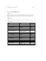
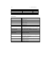
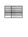
Contents
Table of Contents
3
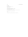
List of Figures
16
1
18
WinDriver Overview
1.1
Introduction to WinDriver
. . . . . . . . . . . . . . . . . . . . . .
18
1.2
Background . . . . . . . . . . . . . . . . . . . . . . . . . . . . . .
19
1.2.1
The Challenge . . . . . . . . . . . . . . . . . . . . . . . .
19
1.2.2
The WinDriver Solution . . . . . . . . . . . . . . . . . . .
20
1.3
How Fast Can WinDriver Go? . . . . . . . . . . . . . . . . . . . .
20
1.4
Conclusion . . . . . . . . . . . . . . . . . . . . . . . . . . . . . . .
21
1.5
WinDriver Benefits . . . . . . . . . . . . . . . . . . . . . . . . . .
21
1.6
WinDriver Architecture . . . . . . . . . . . . . . . . . . . . . . . .
23
1.7
What Platforms Does WinDriver Support? . . . . . . . . . . . . . .
24
1.8
Limitations of the Different Evaluation Versions . . . . . . . . . . .
24
1.9
How Do I Develop My Driver with WinDriver? . . . . . . . . . . .
24
1.9.1
On Windows 95, 98, Me, NT, 2000 and XP . . . . . . . . .
24
1.9.2
On Windows CE . . . . . . . . . . . . . . . . . . . . . . .
25
1.9.3
On Linux and Solaris . . . . . . . . . . . . . . . . . . . . .
26
1.9.4
On VxWorks . . . . . . . . . . . . . . . . . . . . . . . . .
26
3
CONTENTS
4
1.10
What Does the WinDriver Toolkit Include? . . . . . . . . . . . . . .
26
1.10.1 WinDriver Modules . . . . . . . . . . . . . . . . . . . . . .
27
1.10.2 Utilities . . . . . . . . . . . . . . . . . . . . . . . . . . . .
28
1.10.3 WinDriver’s Specific Chipset Support . . . . . . . . . . . .
28
1.10.4 Samples . . . . . . . . . . . . . . . . . . . . . . . . . . . .
29
1.11
Can I Distribute the Driver Created with WinDriver? . . . . . . . . .
29
1.12
Device Driver Overview . . . . . . . . . . . . . . . . . . . . . . . .
29
1.12.1 Monolithic Drivers . . . . . . . . . . . . . . . . . . . . . .
30
1.12.2 Windows 95/98/Me Drivers . . . . . . . . . . . . . . . . .
30
1.12.3 NT Driver Model . . . . . . . . . . . . . . . . . . . . . . .
31
1.12.4 Unix Device Drivers . . . . . . . . . . . . . . . . . . . . .
32
1.12.5 Linux Device Drivers . . . . . . . . . . . . . . . . . . . . .
33
1.12.6 Solaris Device Drivers . . . . . . . . . . . . . . . . . . . .
34
Matching the Right Tool for Your Driver . . . . . . . . . . . . . . .
34
1.13
2 WinDriver USB Overview
35
2.1
Introduction to USB . . . . . . . . . . . . . . . . . . . . . . . . . .
35
2.2
WinDriver USB Benefits . . . . . . . . . . . . . . . . . . . . . . .
36
2.3
USB Components . . . . . . . . . . . . . . . . . . . . . . . . . . .
37
2.4
Data Flow in USB Devices . . . . . . . . . . . . . . . . . . . . . .
37
2.5
USB Data Exchange . . . . . . . . . . . . . . . . . . . . . . . . . .
38
2.6
USB Data Transfer Types . . . . . . . . . . . . . . . . . . . . . . .
40
2.7
USB Configuration . . . . . . . . . . . . . . . . . . . . . . . . . .
41
2.8
WinDriver USB . . . . . . . . . . . . . . . . . . . . . . . . . . . .
43
2.9
WinDriver USB Architecture . . . . . . . . . . . . . . . . . . . . .
45
2.10
Which Drivers Can I Write with WinDriver USB? . . . . . . . . . .
46
CONTENTS
3
5
Installation and Setup
47
3.1
System Requirements . . . . . . . . . . . . . . . . . . . . . . . . .
47
3.1.1
For Windows 95 / 98 / Me . . . . . . . . . . . . . . . . . .
47
3.1.2
For Windows NT / 2000 / XP . . . . . . . . . . . . . . . .
47
3.1.3
For Windows CE . . . . . . . . . . . . . . . . . . . . . . .
48
3.1.4
For Linux . . . . . . . . . . . . . . . . . . . . . . . . . . .
48
3.1.5
For Solaris . . . . . . . . . . . . . . . . . . . . . . . . . .
48
3.1.6
For VxWorks . . . . . . . . . . . . . . . . . . . . . . . . .
48
3.2
Installing WinDriver
. . . . . . . . . . . . . . . . . . . . . . . . .
49
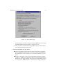
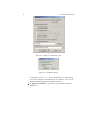
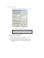
Installing WinDriver for Windows 95, 98, Me, NT, 2000 and
XP . . . . . . . . . . . . . . . . . . . . . . . . . . . . . .
49
3.2.2
Installing WinDriver CE . . . . . . . . . . . . . . . . . . .
50
3.2.3
Installing WinDriver for Linux . . . . . . . . . . . . . . . .
52
3.2.4
Installing WinDriver for Solaris . . . . . . . . . . . . . . .
55
3.2.5
Installing DriverBuilder for VxWorks . . . . . . . . . . . .
57
3.3
Upgrading Your Installation . . . . . . . . . . . . . . . . . . . . . .
59
3.4
Checking Your Installation . . . . . . . . . . . . . . . . . . . . . .
59
3.4.1
On Your Windows Machine . . . . . . . . . . . . . . . . .
59
3.4.2
On Your Windows CE Machine . . . . . . . . . . . . . . .
60
3.4.3
On Your Linux Machine . . . . . . . . . . . . . . . . . . .
60
3.4.4
On Your Solaris Machine . . . . . . . . . . . . . . . . . . .
60
3.4.5
On VxWorks . . . . . . . . . . . . . . . . . . . . . . . . .
61
Uninstalling WinDriver . . . . . . . . . . . . . . . . . . . . . . . .
61
3.2.1
3.5
3.5.1
Uninstalling WinDriver from Windows 95, 98, Me, NT,
2000 and XP . . . . . . . . . . . . . . . . . . . . . . . . .
61
3.5.2
Uninstalling WinDriver from Linux . . . . . . . . . . . . .
62
3.5.3
Uninstalling WinDriver from Solaris . . . . . . . . . . . . .
63
3.5.4
Uninstalling DriverBuilder for VxWorks . . . . . . . . . . .
64
CONTENTS
6
4 Using DriverWizard
65
4.1
An Overview . . . . . . . . . . . . . . . . . . . . . . . . . . . . .
65
4.2
DriverWizard Walkthrough . . . . . . . . . . . . . . . . . . . . . .
66
4.3
DriverWizard Notes . . . . . . . . . . . . . . . . . . . . . . . . . .
76
4.3.1
Sharing a Resource . . . . . . . . . . . . . . . . . . . . . .
76
4.3.2
Disabling a Resource . . . . . . . . . . . . . . . . . . . . .
76
4.3.3
DriverWizard Logger . . . . . . . . . . . . . . . . . . . . .
76
4.3.4
Automatic Code Generation . . . . . . . . . . . . . . . . .
77
5 Developing a Driver
79
5.1
Using the DriverWizard to Build a Device Driver . . . . . . . . . .
79
5.2
Writing the Device Driver Without the DriverWizard . . . . . . . .
80
5.3
Win CE - Testing on CE . . . . . . . . . . . . . . . . . . . . . . . .
82
6 Debugging Drivers
83
6.1
User Mode Debugging . . . . . . . . . . . . . . . . . . . . . . . .
83
6.2
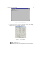
Debug Monitor . . . . . . . . . . . . . . . . . . . . . . . . . . . .
84
6.2.1
84
Using Debug Monitor . . . . . . . . . . . . . . . . . . . .
7 Using the Enhanced Support for PCI and USB Chip Sets
88
7.1
Overview . . . . . . . . . . . . . . . . . . . . . . . . . . . . . . .
88
7.2
What is the PCI Diagnostics Program? . . . . . . . . . . . . . . . .
89
7.3
Using Your PCI Chip-Set Diagnostics Program . . . . . . . . . . .
89
7.3.1
Introduction . . . . . . . . . . . . . . . . . . . . . . . . . .
89
7.3.2
Main Menu Options . . . . . . . . . . . . . . . . . . . . .
90
7.4
Creating Your Driver without Using the PCI Diagnostics Code . . .
92
7.5
WinDriver’s Specific PCI Chip-Set API Function Reference . . . . .
94
7.5.1
xxx_CountCards () . . . . . . . . . . . . . . . . . . . . . .
95
7.5.2
xxx_Open()
96
. . . . . . . . . . . . . . . . . . . . . . . . .
CONTENTS
7
7.5.3
xxx_Close()
. . . . . . . . . . . . . . . . . . . . . . . . .
97
7.5.4
xxx_IsAddrSpaceActive() . . . . . . . . . . . . . . . . . .
98
7.5.5
xxx_GetRevision() . . . . . . . . . . . . . . . . . . . . . .
99
7.5.6
xxx_ReadReg () . . . . . . . . . . . . . . . . . . . . . . . 100
7.5.7
xxx_WriteReg () . . . . . . . . . . . . . . . . . . . . . . . 100
7.5.8
xxx_ReadSpaceByte() . . . . . . . . . . . . . . . . . . . . 101
7.5.9
xxx_ReadSpaceWord()
7.5.10 xxx_ReadSpaceDWord()
7.5.11 xxx_WriteSpaceByte()
. . . . . . . . . . . . . . . . . . . 101
. . . . . . . . . . . . . . . . . . 101
. . . . . . . . . . . . . . . . . . . 102
7.5.12 xxx_WriteSpaceWord() . . . . . . . . . . . . . . . . . . . 102
7.5.13 xxx_WriteSpaceDWord() . . . . . . . . . . . . . . . . . . 102
7.5.14 xxx_ReadSpaceBlock() . . . . . . . . . . . . . . . . . . . 104
7.5.15 xxx_WriteSpaceBlock() . . . . . . . . . . . . . . . . . . . 104
7.5.16 xxx_ReadByte() . . . . . . . . . . . . . . . . . . . . . . . 105
7.5.17 xxx_ReadWord()
7.5.18 xxx_ReadDWord()
7.5.19 xxx_WriteByte()
. . . . . . . . . . . . . . . . . . . . . . 105
. . . . . . . . . . . . . . . . . . . . . 105
. . . . . . . . . . . . . . . . . . . . . . 106
7.5.20 xxx_WriteWord() . . . . . . . . . . . . . . . . . . . . . . 106
7.5.21 xxx_WriteDWord() . . . . . . . . . . . . . . . . . . . . . 106
7.5.22 xxx_ReadBlock() . . . . . . . . . . . . . . . . . . . . . . 108
7.5.23 xxx_WriteBlock() . . . . . . . . . . . . . . . . . . . . . . 108
7.5.24 xxx_IntIsEnabled() . . . . . . . . . . . . . . . . . . . . . . 109
7.5.25 xxx_IntEnable() . . . . . . . . . . . . . . . . . . . . . . . 110
7.5.26 xxx_IntDisable()
. . . . . . . . . . . . . . . . . . . . . . 110
7.5.27 xxx_DMAOpen() . . . . . . . . . . . . . . . . . . . . . . 111
7.5.28 xxx_DMAClose() . . . . . . . . . . . . . . . . . . . . . . 113
7.5.29 xxx_DMAStart()
. . . . . . . . . . . . . . . . . . . . . . 113
CONTENTS
8
7.5.30 xxx_IsDMADone() . . . . . . . . . . . . . . . . . . . . . 113
7.5.31 xxx_PulseLocalReset() . . . . . . . . . . . . . . . . . . . 115
7.5.32 xxx_EEPROMRead() . . . . . . . . . . . . . . . . . . . . 116
7.5.33 xxx_EEPROMWrite() . . . . . . . . . . . . . . . . . . . . 116
7.5.34 xxx_ReadPCIReg () . . . . . . . . . . . . . . . . . . . . . 117
7.5.35 xxx_WritePCIReg() . . . . . . . . . . . . . . . . . . . . . 117
8 Advanced Issues
8.1
8.2
8.3
8.4
118
Performing DMA . . . . . . . . . . . . . . . . . . . . . . . . . . . 118
8.1.1
Scatter/Gather DMA . . . . . . . . . . . . . . . . . . . . . 119
8.1.2
Contiguous Buffer DMA . . . . . . . . . . . . . . . . . . . 121
Handling Interrupts . . . . . . . . . . . . . . . . . . . . . . . . . . 122
8.2.1
General - Handling an Interrupt . . . . . . . . . . . . . . . 122
8.2.2
ISA / EISA and PCI Interrupts . . . . . . . . . . . . . . . . 126
8.2.3
Interrupts in Windows CE . . . . . . . . . . . . . . . . . . 128
USB Control Transfers . . . . . . . . . . . . . . . . . . . . . . . . 129
8.3.1
USB Data Exchange . . . . . . . . . . . . . . . . . . . . . 129
8.3.2
More About the Control Transfer . . . . . . . . . . . . . . . 129
8.3.3
The Setup Packet . . . . . . . . . . . . . . . . . . . . . . . 130
8.3.4
USB Setup Packet Format . . . . . . . . . . . . . . . . . . 132
8.3.5
Standard Device Requests Codes . . . . . . . . . . . . . . . 132
8.3.6
Setup Packet Example . . . . . . . . . . . . . . . . . . . . 133
Performing Control Transfers with WinDriver . . . . . . . . . . . . 134
8.4.1
Control Transfers with DriverWizard . . . . . . . . . . . . . 135
8.4.2
Control Transfers with WinDriver API . . . . . . . . . . . . 136
CONTENTS
9
9
Improving Performance
9.1
Overview . . . . . . . . . . . . . . . . . . . . . . . . . . . . . . . 139
9.1.1
9.2
139
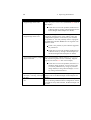
Performance Improvement Checklist . . . . . . . . . . . . . 139
Improving the Performance of a User mode Driver . . . . . . . . . . 141
9.2.1
Using Direct Access to Memory Mapped Regions . . . . . . 141
9.2.2
Accessing I/O Mapped Regions . . . . . . . . . . . . . . . 141
9.2.3
Performing 64-bit data transfers . . . . . . . . . . . . . . . 142
10 Understanding the Kernel PlugIn
143
10.1
Background . . . . . . . . . . . . . . . . . . . . . . . . . . . . . . 143
10.2
Do I Need to Write a Kernel PlugIn? . . . . . . . . . . . . . . . . . 144
10.3
What Kind of Performance Can I Expect? . . . . . . . . . . . . . . 144
10.4
Overview of the Development Process . . . . . . . . . . . . . . . . 144
10.5
The Kernel PlugIn Architecture . . . . . . . . . . . . . . . . . . . . 145
10.5.1 Architecture Overview . . . . . . . . . . . . . . . . . . . . 145
10.5.2 WinDriver Kernel and Kernel PlugIn Interaction . . . . . . 145
10.5.3 Kernel PlugIn Components . . . . . . . . . . . . . . . . . . 146
10.5.4 Kernel PlugIn Event Sequence . . . . . . . . . . . . . . . . 146
10.6
How does Kernel PlugIn Work? . . . . . . . . . . . . . . . . . . . . 149
10.6.1 Minimal Requirements for Creating a Kernel PlugIn . . . . 149
10.6.2 Directory Structure and Sample for the WinDriver Kernel
PlugIn . . . . . . . . . . . . . . . . . . . . . . . . . . . . . 149
10.6.3 Generating Kernel PlugIn Driver Code With DriverWizard . 150
10.6.4 KPTest - A Sample Kernel PlugIn Driver . . . . . . . . . . 151
10.6.5 Kernel PlugIn Implementation . . . . . . . . . . . . . . . . 151
10.6.6 Handling Interrupts in the Kernel PlugIn . . . . . . . . . . . 154
10.6.7 Message Passing . . . . . . . . . . . . . . . . . . . . . . . 156
CONTENTS
10
11 Writing a Kernel PlugIn
158
11.1
Determine Whether a Kernel PlugIn is Needed . . . . . . . . . . . . 158
11.2
Determine What Type of Kernel PlugIn Driver to Develop (On
Windows) . . . . . . . . . . . . . . . . . . . . . . . . . . . . . . . 159
11.3
Use KPTest to Write Your Kernel PlugIn . . . . . . . . . . . . . . . 159
11.3.1 Prepare the user Mode Source Code . . . . . . . . . . . . . 159
11.3.2 Create a New Kernel PlugIn Project . . . . . . . . . . . . . 160
11.3.3 Create a Handle to the WinDriver Kernel PlugIn . . . . . . 160
11.3.4 Set Interrupt Handling in the Kernel PlugIn . . . . . . . . . 160
11.3.5 Set I/O Handling in the Kernel PlugIn . . . . . . . . . . . . 160
11.4
Compile Your Kernel PlugIn Driver . . . . . . . . . . . . . . . . . . 161
11.4.1 Windows - Compiling Kernel PlugIn Driver Generated By
DriverWizard . . . . . . . . . . . . . . . . . . . . . . . . . 161
11.4.2 Windows - Compiling KPTest Based Kernel PlugIn Driver . 162
11.4.3 Compiling Under Linux . . . . . . . . . . . . . . . . . . . 162
11.4.4 Compiling Under Solaris
11.5
. . . . . . . . . . . . . . . . . . 163
Install Your Kernel PlugIn Driver . . . . . . . . . . . . . . . . . . . 163
11.5.1 On Win32 Platforms . . . . . . . . . . . . . . . . . . . . . 163
11.5.2 On Linux . . . . . . . . . . . . . . . . . . . . . . . . . . . 164
11.5.3 On Solaris . . . . . . . . . . . . . . . . . . . . . . . . . . . 165
12 Dynamically Loading Your Driver
12.1
166
Windows NT/2000/XP and 95/98/Me . . . . . . . . . . . . . . . . . 166
12.1.1 Dynamic Loading - Background . . . . . . . . . . . . . . . 166
12.1.2 Why Do You Need a Dynamically Loadable Driver? . . . . 166
12.1.3 The WDREG utility . . . . . . . . . . . . . . . . . . . . . 167
12.1.4 Dynamically Loading WINDRVR . . . . . . . . . . . . . . 169
12.1.5 Dynamically Loading Your Kernel PlugIn . . . . . . . . . . 170
12.2
Linux . . . . . . . . . . . . . . . . . . . . . . . . . . . . . . . . . 171
12.3
Solaris . . . . . . . . . . . . . . . . . . . . . . . . . . . . . . . . . 171
CONTENTS
11
13 Distributing Your Driver
173
13.1
Getting a Valid License for Your WinDriver . . . . . . . . . . . . . 173
13.2
Distributing to Windows 98/Me and 2000/XP . . . . . . . . . . . . 173
13.2.1 Preparing the distribution package . . . . . . . . . . . . . . 174
13.2.2 Installing your driver on the target computer
. . . . . . . . 174
13.2.3 Installing your Kernel PlugIn on the target computer . . . . 177
13.3
Distributing to Windows 95 and NT 4.0 . . . . . . . . . . . . . . . 178
13.3.1 Preparing the distribution package . . . . . . . . . . . . . . 178
13.3.2 Installing your driver on the target computer . . . . . . . . . 178
13.3.3 Installing your Kernel PlugIn on the target computer . . . . 179
13.4
Creating an INF File
. . . . . . . . . . . . . . . . . . . . . . . . . 180
13.4.1 Why Should I Create an INF File?
. . . . . . . . . . . . . 180
13.4.2 How Do I Install an INF File When No Driver Exists? . . . 181
13.4.3 How Do I Replace an Existing Driver Using the INF File? . 183
13.5
Distributing WinDriver extension for custom USB HID devices
. . 185
13.6
Windows CE . . . . . . . . . . . . . . . . . . . . . . . . . . . . . . 185
13.7
Linux . . . . . . . . . . . . . . . . . . . . . . . . . . . . . . . . . 186
13.7.1 WinDriver Kernel Module . . . . . . . . . . . . . . . . . . 187
13.7.2 Your User Mode Driver . . . . . . . . . . . . . . . . . . . . 187
13.7.3 Kernel PlugIn Modules . . . . . . . . . . . . . . . . . . . . 187
13.7.4 Installation Script . . . . . . . . . . . . . . . . . . . . . . . 188
13.8
Solaris . . . . . . . . . . . . . . . . . . . . . . . . . . . . . . . . . 188
13.8.1 Installation Script . . . . . . . . . . . . . . . . . . . . . . . 188
13.9
VxWorks . . . . . . . . . . . . . . . . . . . . . . . . . . . . . . . . 188
CONTENTS
12
14 Troubleshooting
190
14.1
WD_Open() (or xxx_Open()) Fails. . . . . . . . . . . . . . . . . . . 190
14.2
WD_CardRegister Fails . . . . . . . . . . . . . . . . . . . . . . . . 191
14.3
Can’t Open USB Device Using the DriverWizard . . . . . . . . . . 191
14.4
Can’t Get Interfaces for USB Devices . . . . . . . . . . . . . . . . 191
14.5
PCI Card has No Resources when Using the DriverWizard . . . . . 192
14.6
Computer Hangs on Interrupt . . . . . . . . . . . . . . . . . . . . . 192
A Function Reference
A.1
195
General Use . . . . . . . . . . . . . . . . . . . . . . . . . . . . . . 195
A.1.1 Calling Sequence WinDriver - General Use . . . . . . . . . 195
A.1.2 WD_Open() . . . . . . . . . . . . . . . . . . . . . . . . . . 197
A.1.3 WD_Version() . . . . . . . . . . . . . . . . . . . . . . . . 199
A.1.4 WD_Close() . . . . . . . . . . . . . . . . . . . . . . . . . 200
A.1.5 WD_Debug() . . . . . . . . . . . . . . . . . . . . . . . . . 201
A.1.6 WD_DebugAdd() . . . . . . . . . . . . . . . . . . . . . . . 204
A.1.7 WD_DebugDump() . . . . . . . . . . . . . . . . . . . . . . 206
A.1.8 WD_Sleep() . . . . . . . . . . . . . . . . . . . . . . . . . 208
A.1.9 WD_License() . . . . . . . . . . . . . . . . . . . . . . . . 210
A.2
PCI/ISA . . . . . . . . . . . . . . . . . . . . . . . . . . . . . . . . 212
A.2.1 Calling Sequence WinDriver - PCI/ISA . . . . . . . . . . . 212
A.2.2 WD_PciScanCards() . . . . . . . . . . . . . . . . . . . . . 214
A.2.3 WD_PciGetCardInfo() . . . . . . . . . . . . . . . . . . . . 217
A.2.4 WD_PciConfigDump() . . . . . . . . . . . . . . . . . . . . 220
A.2.5 WD_IsapnpScanCards() . . . . . . . . . . . . . . . . . . . 222
A.2.6 WD_IsapnpGetCardInfo() . . . . . . . . . . . . . . . . . . 225
A.2.7 WD_IsapnpConfigDump() . . . . . . . . . . . . . . . . . . 228
A.2.8 WD_CardRegister() . . . . . . . . . . . . . . . . . . . . . 230
CONTENTS
13
A.2.9 WD_CardUnregister() . . . . . . . . . . . . . . . . . . . . 234
A.2.10 WD_Transfer() . . . . . . . . . . . . . . . . . . . . . . . . 235
A.2.11 WD_MultiTransfer() . . . . . . . . . . . . . . . . . . . . . 238
A.2.12 WD_DMALock() . . . . . . . . . . . . . . . . . . . . . . . 241
A.2.13 WD_DMAUnlock() . . . . . . . . . . . . . . . . . . . . . 244
A.2.14 InterruptThreadEnable() . . . . . . . . . . . . . . . . . . . 246
A.2.15 InterruptThreadDisable() . . . . . . . . . . . . . . . . . . . 250
A.3
PCI/ISA - Low Level Functions . . . . . . . . . . . . . . . . . . . . 252
A.3.1 Calling Sequence WinDriver - Low Level . . . . . . . . . . 252
A.3.2 WD_IntEnable() . . . . . . . . . . . . . . . . . . . . . . . 252
A.3.3 WD_IntWait() . . . . . . . . . . . . . . . . . . . . . . . . 256
A.3.4 WD_IntCount() . . . . . . . . . . . . . . . . . . . . . . . . 258
A.3.5 WD_IntDisable() . . . . . . . . . . . . . . . . . . . . . . . 260
A.4
USB . . . . . . . . . . . . . . . . . . . . . . . . . . . . . . . . . . 262
A.4.1 Calling Sequence WinDriver - USB . . . . . . . . . . . . . 262
A.4.2 WD_UsbScanDevice() . . . . . . . . . . . . . . . . . . . . 263
A.4.3 WD_UsbGetConfiguration() . . . . . . . . . . . . . . . . . 267
A.4.4 WD_UsbDeviceRegister() . . . . . . . . . . . . . . . . . . 271
A.4.5 WD_UsbDeviceUnregister() . . . . . . . . . . . . . . . . . 274
A.4.6 WD_UsbTransfer() . . . . . . . . . . . . . . . . . . . . . . 276
A.4.7 WD_UsbResetPipe() . . . . . . . . . . . . . . . . . . . . . 279
A.4.8 WD_UsbResetDevice() . . . . . . . . . . . . . . . . . . . . 281
A.4.9 WD_UsbResetDeviceEx() . . . . . . . . . . . . . . . . . . 282
A.5
Plug-and-Play and Power Management . . . . . . . . . . . . . . . . 284
A.5.1 Calling Sequence . . . . . . . . . . . . . . . . . . . . . . . 284
A.5.2 event_register() . . . . . . . . . . . . . . . . . . . . . . . . 285
A.5.3 event_unregister() . . . . . . . . . . . . . . . . . . . . . . . 289
CONTENTS
14
A.6
Plug-and-Play and Power Management - Low Level Functions . . . 290
A.6.1 Calling Sequence . . . . . . . . . . . . . . . . . . . . . . . 290
A.6.2 WD_EventRegister() . . . . . . . . . . . . . . . . . . . . . 291
A.6.3 WD_EventUnregister() . . . . . . . . . . . . . . . . . . . . 294
A.6.4 WD_EventPull() . . . . . . . . . . . . . . . . . . . . . . . 296
A.6.5 WD_EventSend() . . . . . . . . . . . . . . . . . . . . . . . 299
A.7
Kernel PlugIn - User Mode Functions . . . . . . . . . . . . . . . . 301
A.7.1 WD_KernelPlugInOpen() . . . . . . . . . . . . . . . . . . 301
A.7.2 WD_KernelPlugInClose() . . . . . . . . . . . . . . . . . . 303
A.7.3 WD_KernelPlugInCall() . . . . . . . . . . . . . . . . . . . 304
A.7.4 WD_IntEnable() . . . . . . . . . . . . . . . . . . . . . . . 306
A.8
Kernel PlugIn - Kernel Mode Functions . . . . . . . . . . . . . . . 308
A.8.1 KP_Init() . . . . . . . . . . . . . . . . . . . . . . . . . . . 308
A.8.2 KP_Open() . . . . . . . . . . . . . . . . . . . . . . . . . . 310
A.8.3 KP_Close() . . . . . . . . . . . . . . . . . . . . . . . . . . 312
A.8.4 KP_Call() . . . . . . . . . . . . . . . . . . . . . . . . . . . 313
A.8.5 KP_Event() . . . . . . . . . . . . . . . . . . . . . . . . . . 315
A.8.6 KP_IntEnable() . . . . . . . . . . . . . . . . . . . . . . . . 316
A.8.7 KP_IntDisable() . . . . . . . . . . . . . . . . . . . . . . . 318
A.8.8 KP_IntAtIrql() . . . . . . . . . . . . . . . . . . . . . . . . 319
A.8.9 KP_IntAtDpc() . . . . . . . . . . . . . . . . . . . . . . . . 321
A.8.10 COPY_TO_USER_OR_KERNEL
and
COPY_FROM_USER_OR_KERNEL() . . . . . . . . . . . 323
A.9
Kernel PlugIn - Structure Reference . . . . . . . . . . . . . . . . . 324
A.9.1 WD_KERNEL_PLUGIN
. . . . . . . . . . . . . . . . . . 324
A.9.2 WD_INTERRUPT . . . . . . . . . . . . . . . . . . . . . . 325
A.9.3 WD_KERNEL_PLUGIN_CALL . . . . . . . . . . . . . . 326
A.9.4 KP_INIT . . . . . . . . . . . . . . . . . . . . . . . . . . . 327
A.9.5 KP_OPEN_CALL . . . . . . . . . . . . . . . . . . . . . . 328
CONTENTS
15
B Limitations of the Different Evaluation Versions
330
C Purchasing WinDriver
333
D Distributing Your Driver - Legal Issues
335
List of Figures
1.1
WinDriver Architecture . . . . . . . . . . . . . . . . . . . . . . . . .
23
1.2
Monolithic Drivers . . . . . . . . . . . . . . . . . . . . . . . . . . .
30
1.3
Layered Drivers . . . . . . . . . . . . . . . . . . . . . . . . . . . . .
31
1.4
Miniport Drivers . . . . . . . . . . . . . . . . . . . . . . . . . . . .
32
2.1
USB Endpoints . . . . . . . . . . . . . . . . . . . . . . . . . . . . .
38
2.2
USB Pipes . . . . . . . . . . . . . . . . . . . . . . . . . . . . . . . .
39
2.3
WinDriver USB Architecture . . . . . . . . . . . . . . . . . . . . . .
45
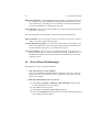
4.1
Selection of PnP Device . . . . . . . . . . . . . . . . . . . . . . . .
67
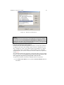
4.2
DriverWizard INF File Information . . . . . . . . . . . . . . . . . . .
68
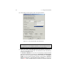
4.3
USB Device Configuration . . . . . . . . . . . . . . . . . . . . . . .
70
4.4
A PCI Diagnostics Screen . . . . . . . . . . . . . . . . . . . . . . .
71
4.5
USB Diagnostics Screen . . . . . . . . . . . . . . . . . . . . . . . .
72
4.6
Generate Code Option . . . . . . . . . . . . . . . . . . . . . . . . .
72
4.7
Select Driver Type . . . . . . . . . . . . . . . . . . . . . . . . . . .
73
4.8
Options for Generating Code . . . . . . . . . . . . . . . . . . . . . .
74
4.9
Notification Events . . . . . . . . . . . . . . . . . . . . . . . . . . .
74
4.10 INF Generation . . . . . . . . . . . . . . . . . . . . . . . . . . . . .
75
16
LIST OF FIGURES
17
6.1
Start Debug Monitor . . . . . . . . . . . . . . . . . . . . . . . . . .
85
6.2
Set Trace Options . . . . . . . . . . . . . . . . . . . . . . . . . . . .
85
8.1
USB Data Exchange . . . . . . . . . . . . . . . . . . . . . . . . . . 130
8.2
USB Read and Write . . . . . . . . . . . . . . . . . . . . . . . . . . 131
8.3
Pipe Selection . . . . . . . . . . . . . . . . . . . . . . . . . . . . . . 135
8.4
USB Pipes . . . . . . . . . . . . . . . . . . . . . . . . . . . . . . . . 135
8.5
Log Screen . . . . . . . . . . . . . . . . . . . . . . . . . . . . . . . 136
10.1 Kernel PlugIn Architecture . . . . . . . . . . . . . . . . . . . . . . . 145
10.2 Interrupt Handling without Kernel PlugIn . . . . . . . . . . . . . . . 155
10.3 Interrupt Handling with the Kernel PlugIn . . . . . . . . . . . . . . . 156
Chapter 1
WinDriver Overview
In this chapter you will explore the uses of WinDriver, and learn the basic steps of
creating your driver.
1.1
Introduction to WinDriver
WinDriver is a development toolkit that dramatically simplifies the difficult
task of creating device drivers and hardware access applications. The driver
and application you develop using WinDriver is source code compatible
between all supported operating systems (WinDriver currently supports Windows
95/98/Me/NT/2000/XP/CE, Linux, Solaris and VxWorks.). The driver is binary
compatible between Windows 95/98/Me/NT/2000/XP. Bus architecture support
includes PCI/CardBus/ISA/ISAPnP/EISA/CompactPCI and USB. WinDriver
provides a complete solution for creating high performance drivers, which handle
interrupts and I/O at optimal rates.
Don’t let the size of this manual fool you – WinDriver makes developing device
drivers an easy task that takes hours instead of months. Most developers will find that
reading this chapter and glancing through the DriverWizard and function reference
chapters is all they need to successfully write their driver.
The major part of this manual deals with the features that WinDriver offers to the
advanced user.
WinDriver supports all USB and PCI bridges, from all vendors. Enhanced support is
offered for the PLX / Altera / Marvell / PLDA / AMCC and QuickLogic PCI chips.
18
WinDriver 5.22 User’s Guide
19
A special chapter is dedicated to developers of USB devices and PCI card drivers
who are using USB and PCI chips from these vendors. The final chapters of this
manual explain how to tune your driver code to achieve optimal performance, with
special emphasis on the Kernel PlugIn feature of WinDriver. This feature allows
the developer to write and debug the entire device driver in the user mode, and later
drop performance critical parts into the Kernel mode. Therefore, the driver achieves
optimal Kernel mode performance, with user mode ease of development.
Visit Jungo’s web site at http://www.jungo.com for the latest news about
WinDriver and other driver development tools that Jungo offers.
Good luck with your project!
1.2
Background
1.2.1
The Challenge
In protected operating systems (such as Windows, Linux and Solaris), a programmer
cannot access hardware directly from the application level (the user mode) where
development work is usually done. Hardware access is allowed only from within
the operating system itself (the Kernel mode or Ring 0), by software modules called
device drivers. In order to access a custom hardware device from the application
level, a programmer must do the following:
Learn the internals of the operating system he is working on (Windows
95/98/Me/NT/2000/XP/CE, Linux, Solaris and VxWorks).
Learn how to write a device driver.
Learn new tools for developing / debugging in the Kernel mode (DDK, ETK,
DDI/DKI).
Write the Kernel mode device driver that does the basic hardware input/output.
Write the application in the User mode, which accesses the hardware through
the device driver written in the Kernel mode.
Repeat the first four steps for each new operating system on which the code
should run.
1 WinDriver Overview
20
1.2.2
The WinDriver Solution
Easy Development - WinDriver enables Windows programmers to create
PCI/CardBus/ISA/ISAPnP/EISA/CompactPCI and USB based device drivers
in an extremely short time. WinDriver allows you to create your driver in
the user mode in the familiar environment - Using MSDEV, Visual C/C++,
Borland Delphi, Borland C++, Visual Basic, GCC or any other 32 bit compiler.
WinDriver eliminates the need for you to be familiar with the operating system
internals, kernel programming or with the DDK, ETK, DDI / DKI or have any
device driver knowledge.
Cross Platform - The driver created with WinDriver will run on
Windows 95/98/Me/NT/2000/XP/CE, Linux, Solaris and VxWorks,
- i.e., write once - Run on many platforms.
Friendly Wizards - DriverWizard (included) is a graphical diagnostics tool that lets
you write to, and read from the hardware, before writing a single line of code.
With a few clicks of the mouse, the hardware is diagnosed - Memory ranges
are read, registers are toggled and interrupts are checked. Once the device is
operating to your satisfaction, DriverWizard creates the skeletal driver source
code, giving access functions to all the resources on the hardware.
Kernel Mode Performance - WinDriver’s API is optimized for performance. For
drivers that need Kernel mode performance, WinDriver offers the Kernel
PlugIn. This powerful feature enables you to create and debug your code in the
user mode, and run the performance critical parts of your code, (such as the
interrupt handler, or access to I/O mapped memory ranges), in Kernel mode,
thereby achieving Kernel mode performance (zero performance degradation).
This unique feature allows the developer to run the user mode code in the OS
kernel without having to learn how the kernel works. When working with
Windows CE or VxWorks, there is no need to use the Kernel PlugIn since
in Windows CE and VxWorks there is no separation between user mode and
Kernel mode. This enables you to achieve optimal performance from the user
mode code.
1.3
How Fast Can WinDriver Go?
Using the WinDriver Kernel PlugIn you can expect the same throughput as a custom
kernel driver. You are limited only by your operating system and hardware limitations.
WinDriver 5.22 User’s Guide
21
A ballpark figure of the throughput you can reach using the Kernel PlugIn would be
about 100,000 interrupts per second.
1.4
Conclusion
Using WinDriver, all a developer has to do to create an application that accesses the
custom hardware is:
Start DriverWizard and detect the hardware and its resources.
Automatically generate the device driver code from within DriverWizard.
Call the generated functions from the user mode application.
The new hardware access application now runs on all Windows platforms (including
CE), on Linux, on Solaris and on VxWorks (just recompile).
1.5
WinDriver Benefits
Easy User mode driver development.
Kernel PlugIn for high performance drivers.
Friendly DriverWizard allows hardware diagnostics without writing a single
line of code.
DriverWizard automatically generates the driver code for the project in C\C++
or Delphi (Pascal).
Supports any PCI/CardBus/ISA/ISAPnP/EISA/CompactPCI and USB device
regardless of manufacturer.
Enhanced support for PLX 9030/9050/9052/9054/9060/9080/IOP 480, Altera,
Marvell, QuickLogic, PLDA, and AMCC PCI bridges, allows the developer to
disregard the PCI bridge details.
Applications are binary-compatible across Windows 95/98/Me/NT/2000/XP.
Applications are source code compatible across Windows
95/98/Me/NT/2000/XP/CE, Linux, Solaris and VxWorks.
1 WinDriver Overview
22
WinDriver can be used with common development environments including
MSDEV, Visual C/C++, Borland Delphi, Borland C++, Visual Basic, GCC or
any other 32 compiler.
No DDK, ETK, DDI or any system-level programming knowledge is required.
Supports I/O, DMA, Interrupt handling and access to memory mapped cards.
Supports multiple CPU and multiple PCI bus platforms.
Includes dynamic driver loader.
Comprehensive documentation and help files.
Detailed examples in C, Delphi and Visual Basic are included.
Two months of free technical support.
No run time fees or royalties.
WinDriver 5.22 User’s Guide
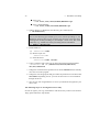
1.6
23
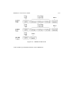
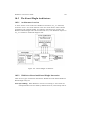
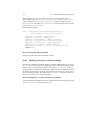
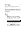
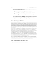
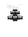
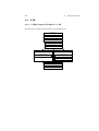
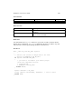
WinDriver Architecture
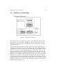
Figure 1.1: WinDriver Architecture
For hardware access, your application calls one of the WinDriver functions from
the WinDriver User mode library (windrvr.h). The User mode library calls the
WinDriver kernel, which accesses the hardware for you, through the native calls of
the operating system.
WinDriver’s design minimizes performance hits on your code, even though it is
running in the User mode. However, some hardware drivers have high performance
requirements, that cannot be achieved in User mode. This is where WinDriver’s edge
sharpens - After easily creating and debugging your code in User mode, you may
drop the performance critical modules of your code (such as a hardware interrupt
handler) into the WinDriver Kernel PlugIn without changing a single line of it. Now,
WinDriver kernel calls this module from the Kernel mode, thereby achieving maximal
performance. This allows you to program and debug in the User mode, and still
achieve kernel performance where needed. In Windows CE and VxWorks there is no
separation between User mode and Kernel mode, therefore you may achieve optimal
performance directly from the User mode, eliminating the need to use the Kernel
PlugIn in these operating systems.
1 WinDriver Overview
24
1.7
What Platforms Does WinDriver Support?
WinDriver supports Windows 95/98/Me/NT/2000/XP/CE, Linux, Solaris and
VxWorks. The same source code will run on all supported platforms. The same
executable you create will operate on Windows Windows 95/98/Me/NT/2000/XP.
Even if your code is meant only for one of these operating systems, using WinDriver
will give you the flexibility of moving your driver to the other operating system
without changing your code.
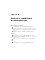
1.8
Limitations of the Different Evaluation Versions
All the evaluation versions of WinDriver are full featured. No functions are limited or
crippled in any way. The following is a list of the differences between the evaluation
versions and the registered ones:
Each time WinDriver is activated, an Un-registered message appears.
When using the DriverWizard, a dialog box with a message stating that an
evaluation version is being run, is popped up on every interaction with the
hardware.
In the Linux, Solaris, VxWorks and CE versions - The driver is operational for
60 minutes after which it has to be restarted.
The Windows evaluation version expires 30 days from the date of installation.
For more details please refer to appendix B.
1.9
1.9.1
How Do I Develop My Driver with WinDriver?
On Windows 95, 98, Me, NT, 2000 and XP
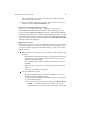
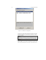
1. Start DriverWizard (Please refer to Chapter 4 for more details).
2. Diagnose your card using DriverWizard.
WinDriver 5.22 User’s Guide
25
3. Let DriverWizard generate skeletal code for your driver. The code generated
by DriverWizard is in fact a diagnostics program that contains functions that
read and write to any resource detected or defined (including custom defined
registers), enables your card’s interrupts and listens to them.
4. Modify the code generated by DriverWizard to suit your particular application
needs.
5. Run and debug your driver in the User mode.
6. If your code contains performance critical sections, improve their performance
(see Chapter 9).
1.9.2
On Windows CE
1. Plug your hardware into a Windows host machine.
2. Activate Visual C++ for CE on the host machine.
3. Diagnose your hardware using DriverWizard.
4. Let DriverWizard generate your driver’s skeletal code.
5. Modify this code using Visual C++ to meet your specific needs.
6. Test and debug your code and hardware from the CE emulation running on the
host machine.
7. If your code contains performance critical sections, improve their performance
by referring to Chapter 9.
NOTE:
ISAPnP is not supported under Windows CE.
TIP!
If you cannot plug your hardware into your NT machine, you may still use
DriverWizard by manually entering all your resources into it. Let DriverWizard
generate your code and then test it on your hardware using a serial connection. After
verifying that the generated code works properly, modify it to meet your specific
needs. You may also use (or combine) any of the sample files for your driver’s
skeletal code.
1 WinDriver Overview
26
1.9.3
On Linux and Solaris
Starting from version 5.0, WinDriver offers a GUI DriverWizard that facilitates driver
development on Linux and Solaris. Use the GUI DriverWizard for Linux and Solaris
in the same way as the DriverWizard on Windows to generate Linux and Solaris code.
If you are using WinDriver 4.x or an older version, and you do not use the Linux or
Solaris X11 GUI, you may wish to consider using Windows as an initial development
platform.
If you do not have a Windows machine, you may use the sample files included with
WinDriver as skeletons for your driver and change them to meet your needs, using the
WinDriver API.
1.9.4
On VxWorks
1. Plug your hardware into a Windows host machine.
2. Diagnose your hardware using DriverWizard for Windows.
3. Let DriverWizard generate your driver’s skeletal code and project makefile for
Tornado.
4. Move the code to your tornado environment and compile it.
5. Modify this code using tornado development environment or any other 32-bit
development environment to meet your specific needs.
1.10
What Does the WinDriver Toolkit Include?
The WinDriver CD.
A printed version of this manual.
Two months of free technical support (Phone / Fax / Email).
WinDriver CE license, enabling you to run your CE driver code on your NT
machine using CE emulation.
WinDriver 5.22 User’s Guide
27
WinDriver Linux and Solaris licenses, enabling you to use DriverWizard on
a Windows machine to diagnose hardware and automatically generate driver
skeletal code. You can then compile and run the code on your Linux / Solaris
machine. The code will not run on your Windows machine without WinDriver
for Windows licensing.
WinDriver modules.
Utilities.
Chipset support APIs.
Sample files.
1.10.1
WinDriver Modules
WinDriver - (WinDriver\include) - The general purpose hardware access
toolkit. The main files here are:
– windrvr.h: the WinDriver API, data structures and constants are defined
in this header file.
– windrvr_int_thread.h: a convenience header file, that contains wrapper
functions to simplify interrupt handling.
DriverWizard (Start Menu | Programs | WinDriver | DriverWizard) - A
graphical tool that diagnoses your hardware and lets you easily code your
driver.
Graphical Debugger (Start Menu | Programs | WinDriver | Debug
Monitor) - A graphical debugging tool which collects information about
your driver as it runs. On Linux, Solaris, WinCE and VxWorks, you can use
the console version of this program.
WinDriver distribution package (WinDriver\redist) - The files you include in
the driver distribution to customers.
WinDriver Kernel PlugIn (WinDriver\kerplug) - The files and samples needed
to create a Kernel PlugIn for WinDriver.
This manual (Start Menu | Programs | WinDriver) - The full WinDriver
manual (this document), in PDF, Windows Help and HTML formats.
1 WinDriver Overview
28
1.10.2
Utilities
PCI_SCAN.EXE (\WinDriver\util\pci_scan.exe) - Enables you to get a list
of the PCI cards installed and the resources allocated for each of them.
PCI_DUMP.EXE (\WinDriver\util\pci_dump.exe) - Used for getting a dump
of all the PCI configuration registers of the PCI cards installed.
USB_DIAG.EXE (\WinDriver\util\usb_diag.exe) - Provides a list of the
USB devices installed, the resources allocated for each one of them, and for
accessing the USB devices.
The CE version includes:
\REDIST\... \X86EMU\WINDRVR_CE_EMU.DLL: This DLL
communicates with the WinDriver kernel, for the X86 HPC emulation mode of
Windows CE.
\REDIST\... \X86EMU\WINDRVR_CE_EMU.LIB: An import library, used
for linking with WinDriver applications that are compiled for the X86 HPC
emulation mode of Windows CE.
1.10.3
WinDriver’s Specific Chipset Support
These are APIs that support the major PCI bridge chipsets, for even faster code
development:
WinDriver PLX APIs (for the 9030, 9050, 9052, 9054, 9060, 9080, 9056 and
9656 PCI bridges) - WinDriver\plx\9050 and \9054, \9060, \9080 respectively.
WinDriver Marvell APIs (for the Marvell GT64 PCI bridges) WinDriver\marvell\gt64.
WinDriver AMCC APIs (for the AMCC S5933 PCI bridges) WinDriver\amcc.
WinDriver ALTERA (for Altera PCI cores) - WinDriver\altera.
WinDriver QuickLogic APIs (for the QuickLogic PCI bridges) WinDriver\QuickLogic.
WinDriver 5.22 User’s Guide
29
Each of the directories above includes the following subdirectories:
\lib - The special chipset API for the PLX / AMCC / QuickLogic/ Altera
chipset, written using the WinDriver API.
\xxx_diag - A sample diagnostics application, which was written using the
special library functions available for the chipsets. This application may be
compiled and executed as-is (xxx_diag i.e., p9054_diag.c for the PLX 9054
chip).
1.10.4
Samples
Here you will find the source code for the utilities listed earlier, along with other
samples which show how to perform the various driver tasks. Find the sample closest
to the driver you need and use it to jump-start your driver development process:
WinDriver samples (WinDriver\samples) - Samples which demonstrate
different common drivers.
WinDriver for Altera / AMCC / Cypress / Marvel / PLX / Quicklogic samples
(e.g., WinDriver\PLX\p9054_diag or WinDriver\Cypress\bulk_sample etc.)
- Source code of the diagnostics applications for the specific chipsets that
WinDriver supports.
1.11
Can I Distribute the Driver Created with
WinDriver?
Yes. WinDriver is purchased as a development toolkit, and any device driver created
using WinDriver may be distributed royalty free in as many copies as you wish. See
the license agreement (WinDriver\docs\license.txt) for more details.
1.12
Device Driver Overview
This section provides an overview of the common device driver architectures.
1 WinDriver Overview
30
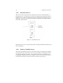
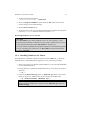
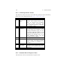
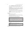
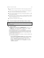
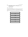
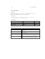
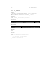
1.12.1
Monolithic Drivers
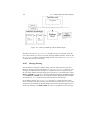
These are the device drivers that are primarily used to drive custom hardware. A
monolithic driver is accessed by one or more user applications, and directly drives a
hardware device. The driver communicates with the application through I/O control
commands - (IOCTLs), and drives the hardware using calls to the different DDK,
ETK, DDI / DKI functions.
Figure 1.2: Monolithic Drivers
Monolithic drivers exist in all operating systems including all Windows platforms and
all Unix platforms.
1.12.2
Windows 95/98/Me Drivers
We use the term Windows drivers for VxD drivers that run on Windows 95, Windows
98 and Windows Me. These drivers do not work on Windows NT. Windows drivers
are typically monolithic in nature. They provide direct access to hardware and
privileged operating system functions. Windows drivers can be stacked or layered in
any fashion, but the driver structure itself does not impose any layering.
WinDriver 5.22 User’s Guide
1.12.3
31
NT Driver Model
Other than monolithic drivers, Windows NT uses other kinds of drivers: layered and
miniport drivers. These drivers are generally unique to Windows NT, but subsets or
minor variations of which might be supported on other Windows versions.
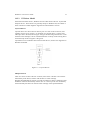
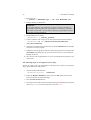
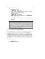
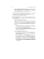
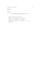
Layered Drivers
Layered drivers are device drivers that are part of a stack of device drivers, that
together process an I/O request. An example of a layered driver is a driver that
intercepts calls to the disk, and encrypts / decrypts all data being transferred to / from
the disk. In this example, a driver would be hooked on to the top of the existing driver
and would only do the encryption / decryption.
Layered drivers are sometimes also known as filter drivers, and are also supported in
Windows 95/98/Me.
Figure 1.3: Layered Drivers
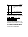
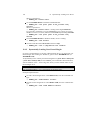
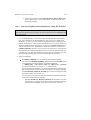
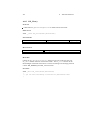
Miniport Drivers
There are classes of device drivers in which, much of the code has to do with the
functionality of the device, and not with the device’s inner workings.
Windows NT/2000/XP, for instance, provides several driver classes (called ports) that
handle the common functionality of their class. It is then up to the user to add only
the functionality that has to do with the inner workings of the specific hardware.
1 WinDriver Overview
32
Figure 1.4: Miniport Drivers
An example for a miniport driver is the NDIS miniport driver. The NDIS
miniport framework is used to create network drivers that hook up to NT’s
communication stacks, and are therefore accessible to common communication
calls used by applications. The Windows NT kernel provides drivers for the different
communication stacks, and other code that is common to communication cards. Due
to the NDIS framework, the network card developer does not have to write all of this
code, only the code that is specific to the network card he is developing.
1.12.4
Unix Device Drivers
In the classic Unix driver model, devices belong to on of three categories, character
(char) devices, block devices and network devices. Drivers that implement these
devices are correspondingly known as char drivers, block drivers or network drivers.
Under Unix, drivers are code units that are linked into the kernel, and run in privileged
Kernel mode. Generally, driver code runs on behalf of the User mode application.
Access to Unix drivers from User mode applications is provided via the filesystem.
In other words, devices appear to the applications as special device files that can be
opened.
Character (also referred to as "char") devices can be accessed as files, and are
implemented by char drivers. These drivers usually implement the open,
close, read, write and ioctl system calls. The console and the serial port are
examples of devices that are implemented by char drivers. Applications access
WinDriver 5.22 User’s Guide
33
char devices through files known as device nodes, such as /dev/console or
/dev/ttyS0.
Block Block devices are also accessed as files, and are implemented by block
drivers. These devices are generally used to represent hardware on which you
can implement a file system. Typically, block devices are accessed by multiples
of a block of data at a time. Block sizes are typically 512 bytes or 1 Kilobyte.
Block drivers interface with the kernel through a similar interface as a char
driver. The device node for a block device shows differently in the filesystem
listing.
Network Network interfaces are used to perform network transactions between
applications residing on a network. A network interface may work through a
hardware device or sometimes be implemented completely in software, like the
loopback interface. User applications perform network transactions through
interfaces to the kernel network subsystem (usually exposed as an API, such
as sockets and pipes). Network interfaces send and receive network packets on
behalf of user applications, without regard to how each individual transaction
maps to actual packets being transmitted.
Network interfaces don’t easily fit into the block or char philosophy, and
therefore are not visible as device nodes in the filesystem. They are represented
by system wide unique logical names such as eth0. Clearly, network interfaces
are not accessed via the open/read/write ... system calls. Instead they are
accessed through network APIs, such as sockets, pipes, RPC, etc.
1.12.5
Linux Device Drivers
Linux device drivers are based on the classic Unix device driver model. In addition,
Linux introduces some new characteristics.
Under Linux, block devices can also be accessed like a character device, but have an
additional block oriented interface which is invisible to the user or application.
Traditionally, under Unix, device drivers had to be linked with the kernel, and the
system had to be brought down and restarted after installing a new driver. Linux
introduced the concept of a dynamically loadable driver called a module. Linux
modules can be loaded or removed dynamically without requiring the system to be
shut down. All Linux drivers can be written so that they are statically linked, or in
modular form, which makes them dynamically loadable. This makes Linux memory
usage very efficient because modules can be written to probe for their own hardware
and unload themselves if they cannot find the hardware they are looking for.
1 WinDriver Overview
34
1.12.6
Solaris Device Drivers
Solaris device drivers are also based on the classic Unix device driver model. Like
Linux, Solaris drivers may either be statically linked with the kernel, or may be
dynamically loaded and removed, from the kernel.
1.13
Matching the Right Tool for Your Driver
Jungo offers two driver development products: WinDriver and KernelDriver.
WinDriver is designed for monolithic type User mode drivers. It enables you to
access your hardware directly from within your Win32 application, without
writing a Kernel mode device driver. Using WinDriver you can either access
your hardware directly from your application (in User mode) or write a DLL
that you can call from many different applications.
In addition, WinDriver provides a complete solution for high performance
drivers. Using WinDriver’s Kernel PlugIn, you can drop your User mode code
into the kernel and reach full Kernel mode performance.
A driver created with WinDriver runs on Windows 95/98/Me/NT/2000/XP/CE,
Linux, Solaris and VxWorks. Typically, a developer without any previous
driver knowledge can get a driver running in a matter of a few hours (compared
to several weeks with a kernel mode driver).
KernelDriver is intended for situations that require running drivers in Kernel mode.
Network drivers under Linux and Windows for example, almost always need
to reside in the kernel. In addition, kernel programming under Windows
NT is necessary for layered or miniport drivers. The KernelDriver tool kit
allows you to write Kernel mode drivers for Windows platforms (Windows
95/98/Me/NT/2000/XP) and Linux. KernelDriver also offers special support
for Windows NT model drivers - A C++ toolkit that provides classes that
encapsulate thousands of lines of kernel code, enabling you to focus on your
/driver’s added-value functionality, instead of OS internals.
Chapter 2
WinDriver USB Overview
This chapter explores the basic characteristics of the USB bus and introduces
WinDriver USB’s features and architecture.
2.1
Introduction to USB
USB (short for Universal Serial Bus), is an industry standard extension to the PC
architecture, for attaching peripherals to the computer. The Universal Serial Bus
was originally developed in 1995 by leading PC and telecommunication industry
companies, such as Intel, Compaq, Microsoft and NEC. The motivation for the
development of USB, was fueled because of several considerations. Among them are
the needs for an inexpensive and widespread connectivity solution for peripherals in
general and for the Computer Telephony Integration in particular, the need for an easy
to use and flexible method of reconfiguring the PC and a solution for adding a large
number of external peripherals.
The USB interface meets the needs stated above. A single USB port can be used to
connect up to 127 peripheral devices. USB also supports Plug-and-Play installation
and hot swapping. USB 1.1 supports both isochronous and asynchronous data
transfers and has dual speed data transfer; 1.5Mbps (Megabit per second) for low
speed USB devices and 12Mbps for high speed USB devices (much faster than the
original serial port). Cables connecting the device to the PC can be up to five meters
(16.4 feet) long. USB includes built-in power distribution for low power devices, and
35
2 WinDriver USB Overview
36
can provide limited power (maximum: 500mA of current) to devices attached on the
bus.
Because of these benefits, USB is enjoying broad market acceptance today.
USB 2.0 supports a faster signalling rate of 480 Mb/S that is 40 times faster than USB
1.1. USB2.0 is fully forward and backward compatible with USB1.1 and uses the
existing cables and connectors.
USB2.0 supports a connection for higher bandwidth, higher functionality PC
peripherals. In addition, it has the capability to handle more simultaneously running
peripherals.
USB2.0 will benefit many applications like Interactive Gaming, Broadband Internet
Access, Desktop and Web Publishing, Internet Services and Conferencing.
2.2
WinDriver USB Benefits
External connection; easy to use for the end user.
Self identifying peripherals, automatic mapping of function to driver, and
configuration.
Dynamically attachable and re-configurable peripherals.
Suitable for device bandwidths ranging from a few Kb/s to several Mb/s.
Supports isochronous as well as asynchronous transfer types over the same set
of wires.
Supports simultaneous operation of many devices (multiple connections).
Supports up to 127 devices.
Guaranteed bandwidth and low latencies; appropriate for telephony, audio, etc.
(Isochronous transfer may use almost entire bus bandwidth).
Flexibility: Supports a wide range of packet sizes and a wide range of data
rates.
Robustness: Error handling mechanism built into protocol, dynamic insertion
and removal of devices identified in user observed real time.
Synergy with PC industry.
WinDriver 5.22 User’s Guide
37
Optimized for integration in peripheral and host hardware.
Low cost implementation, therefore suitable for development of low cost
peripherals.
Low cost cables and connectors.
Uses commodity technologies.
2.3
Built in power management and distribution.
USB Components
USB Host: The USB host computer is where the USB host controller is installed,
and where the client software / device driver runs. The USB host controller is
the interface between the host and the USB peripherals. The host is responsible
for detecting attachment and removals of USB devices, managing the control
and data flow between the host and the devices, providing power to attached
devices and more.
USB Hub: A USB device that enables connecting additional USB devices to a
single USB port on the USB host. Hubs on the back plane of the hosts are
called root hubs. Other hubs are external hubs.
USB Function: The USB device that is able to transmit or receive data or control
information over the bus, and provides a function. Compound devices provide
multiple functions on the USB bus.
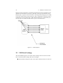
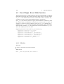
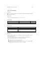
2.4
Data Flow in USB Devices
During the operation of the USB device, data flows between the client software and
the device. The data is moved between memory buffers of the software on the host
and the device, using pipes, which end in endpoints on the device side.
An endpoint is a uniquely identifiable entity on the USB device, which is the source
or the terminus of the data that flows from or to the device. Each USB device, logical
or physical, has a collection of independent endpoints. Endpoint attributes are their
bus access frequency, their bandwidth requirement, their endpoint number, their error
handling mechanism, the maximum packet size that the endpoint can transmit or
receive, their transfer type and their direction (into the device / out of the device).
2 WinDriver USB Overview
38
Pipes are logical components, representing associations between an endpoint on the
USB device and software on the host. The data is moved to and from the device
through a pipe. A pipe can be of two modes: stream pipe and message pipe, according
to the type of data transfer used in that pipe. Pipes, sending data in interrupt, bulk or
isochronous types are stream pipes, while control transfer type is supported by the
message pipes. The different USB transfer types are discussed below:
Figure 2.1: USB Endpoints
2.5
USB Data Exchange
The USB standard supports two kinds of data exchange between the host and the
device: functional data exchange and control exchange:
Functional data exchange is used to move data to and from the device. There are
WinDriver 5.22 User’s Guide
39
three types of data transfers: Bulk transfers, Interrupt transfers and Isochronous
transfers.
Control exchange is used to configure a device when it is first attached and can
also be used for other device specific purposes, including control of other pipes
on the device. The control exchange is transferred via the control pipe (Pipe
00). The control transfer consists of a setup stage (in which a setup packet is
sent from the host to the device), an optional data stage and a status stage.
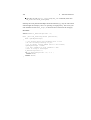
More information on how to implement the control transfer by sending Setup Packets
can be found in chapter 8 that deals with WinDriver Implementation Issues.
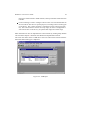
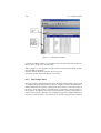
The screen shot below shows a USB device with one bi-directional control and three
functional data transfer pipes / endpoints:
Figure 2.2: USB Pipes
2 WinDriver USB Overview
40
2.6
USB Data Transfer Types
The USB device (function) communicates with the host by transferring data through
a pipe between a memory buffer on the host and an endpoint on the device. USB
provides different transfer types, that best suit the service required by the device and
by the software. The transfer type of a specific endpoint is determined in the endpoint
descriptor.
There are four different types of data transfer within the USB specification:
Control Transfer: Control transfer is mainly intended to support configuration,
command and status operations between the software on the host and the
device. Each USB device has at least one control pipe (default pipe), which
provides access to the configuration, status and control information. The
control pipe is a bi-directional pipe. Control transfer is bursty, non-periodic
communication. Control transfer has a robust error detection, recovery and
retransmission mechanism and retries are made with no involvement of the
driver. Control transfer is used by low speed and high speed devices.
Isochronous Transfer: A type usually used for time dependent information, such
as multimedia streams and telephony. The transfer is periodic and continuous.
The isochronous pipe is uni-directional and a certain endpoint can either
transmit or receive information. For bi-directional isochronous communication
there’s a need to use two isochronous pipes, one in each direction. USB
guarantees the isochronous transfer access to the USB bandwidth (that is it
reserves the required amount of bytes of the USB frame) with bounded latency
and guarantees the data transfer rate through the pipe unless there is less
data transmitted. Up to 90% of the USB frame can be allocated to periodic
transfers (isochronous and interrupt transfers). If, during configuration, there
is no sufficient bus time available for the requester isochronous pipe, the
configuration is not established. Since time is more important than correctness
in these types of transfers, no retries are made in case of error in the data
transfer, though the data receiver can determine the error that occurred on the
bus. Isochronous transfer can be used only by high speed devices.
Interrupt Transfer: Interrupt transfer is intended for devices that send and receive
small amounts of data, in low frequency or in an asynchronous time frame.
An interrupt transfer type guarantees a maximum service period and a retry of
delivery to be attempted in the next period, in case of an error on the bus. The
interrupt pipe, like the isochronous pipe, is uni-directional. The bus access time
period (1-255ms for high speed devices and 10-255ms for low speed devices)
WinDriver 5.22 User’s Guide
41
is specified by the endpoint of the interrupt pipe. Although the host and the
device can count only on the time period indicated by the endpoint, the system
can provide a shorter period up to 1 ms.
Bulk Transfer: Bulk transfer is non-periodic, large packet, bursty communication.
Bulk transfer typically supports devices that transfer large amounts of non-time
sensitive data, and that can use any available bandwidth, such as printers and
scanners. Bulk transfer allows access to the bus on availability basis, guarantees
the data transfer but not the latency and provides error check mechanism with
retries attempts. If part of the USB bandwidth is not being used for other
transfers, the system will use it for bulk transfer. Like previous stream pipes
(isochronous and interrupt) the bulk pipe is also uni-directional. Bulk transfer
can only be used by high speed devices.
2.7
USB Configuration
Before the USB function (or functions in a compound device) can be operated,
the device must be configured. The host does the configuring, by acquiring the
configuration information from the USB device. USB devices report their attributes
by descriptors. A descriptor is the defined structure and format in which the data is
transferred. A complete description of the USB descriptors can be found in Chapter 9
of the USB Specification (See http://www.usb.org for the full specification).
It is best to view the USB descriptors as a hierarchic structure of four levels:
The Device level.
The Configuration level.
The Interface level (this level may include an optional sub-level called alternate
settings).
The Endpoint level.
There is only one device descriptor for each USB device. Each device has one or
more configurations, that have one or more interfaces, and each interface has zero or
more endpoints.
Device Level: At the top level is the device descriptor, that includes general
information about the USB device, that is global information for all of the
42
2 WinDriver USB Overview
device configurations. The device descriptor describes, among other things, the
device class (USB devices are divided into device classes, such as HID devices,
hubs, locator devices etc.), subclass, protocol code, Vendor ID, Device ID and
more. Each USB device has one device descriptor.
Configuration Level: A USB device has one or more configuration descriptors,
which describe the number of interfaces grouped in each configuration
and power attributes of the configuration (such as self-powered, remote
wakeup, maximum power consumption and more). At a given time, only one
configuration is loaded. An example of different configurations of the same
device may be an ISDN adapter, where one configuration presents it with a
single interface of 128KB/s and a second configuration with two interfaces of
64KB/s.
Interface Level: The interface is a related set of endpoints that present a specific
functionality or feature of the device. Each interface may operate independently.
The interface descriptor describes the number of the interface, number of
endpoints used by this interface, and the interface specific class, subclass and
protocol values when the interface operates independently. In addition, an
interface may have alternate settings. The alternate settings allow the endpoints
or their characteristics to be varied after the device is configured.
Endpoint Level: The lowest level is the endpoint descriptor that provides the
host with information regarding the data transfer type of the endpoint and
the bandwidth of each endpoint (the maximum packet size of the specific
endpoint). For isochronous endpoints, this value is used to reserve the bus time
required for the data transfer. Other attributes of the endpoints are their bus
access frequency, their endpoint number, their error handling mechanism, and
their direction.
Seems complicated? Not at all! WinDriver automates the USB configuration process.
The included DriverWizard and USB diagnostics application, scan the USB bus,
detect all USB devices and their different configurations, interfaces, settings and
endpoints, and enables the developer to pick the desired configuration before starting
driver development.
WinDriver identifies the endpoint transfer type as determined in the endpoint
descriptor. The driver created with WinDriver contains all configuration information
acquired at this early stage.
WinDriver 5.22 User’s Guide
2.8
43
WinDriver USB
WinDriver USB enables developers to quickly develop high performance drivers
for USB based devices, without having to learn the USB specifications or the OS
internals. Using WinDriver USB, developers can create USB drivers without having
to use the DDK, and without having to be familiar with Microsoft’s WDM (Win32
Driver Module).
The driver code developed with WinDriver USB is binary compatible between
Windows 98, Windows Me, Windows 2000 and Windows XP.
The source code will be code compatible among all other operating systems, supported
by WinDriver USB. For up to date information regarding operating systems currently
supported by WinDriver USB, please check Jungo’s web site at
http://www.jungo.com.
WinDriver USB encapsulates the USB specification and architecture, letting you
focus on your application logic. WinDriver USB features DriverWizard, with which
you can detect your hardware, configure it and test it before writing a single line of
code. DriverWizard will lead you through the configuration procedure first, enable
you to choose the desirable configuration, interface and alternate setting through a
friendly graphical user interface. After detecting and configuring your USB device,
you can then test it, listen to pipes, write and read packets and ensure that all your
hardware resources function as expected. WinDriver USB is a generic tool kit, which
supports all USB devices, from all vendors and with all types of configurations.
After your hardware is diagnosed, DriverWizard automatically generates your device
driver source code in C or in Delphi. WinDriver USB provides user mode APIs to
your hardware, which you can call from within your application. The WinDriver
USB API is specific for your USB device and includes USB unique operations such
as reset-pipe and reset-device. Along with the device API, WinDriver USB creates a
diagnostics application, which just needs to be compiled and run. You can use this
application as your skeletal driver to jump-start your development cycle. If you are a
VB programmer, you will find all WinDriver USB API supported for you also in VB,
giving you everything you need to develop your driver in VB.
DriverWizard also automates the creation of an INF file where needed. The INF file
is a text file used by the Plug-n-Play mechanisms of Windows 95/98/Me/2000/XP
to load the driver for the newly installed hardware or to replace an existing driver.
The INF file includes all necessary information about the device(s) and the files to
be installed. INF files are required for hardware that identify themselves, such as
USB and PCI. In some cases, the INF file of your specific device is included in the
INF files that are shipped with the operating system. In other cases, you will need to
44
2 WinDriver USB Overview
create an INF file for your device. WinDriver automates this process for you. More
information on how to create your own INF file with DriverWizard can be found in
Chapter 4 that explains the DriverWizard. Installation instructions of INF files can be
found in Chapter 13 that illustrates how to distribute your driver.
Using WinDriver USB, all development is done in the user mode, using familiar
development and debugging tools and your favorite compiler (such as MSDEV,
Visual C/C++, Borland Delphi, Borland C++, Visual Basic).
WinDriver USB API is designed to give you optimized performance. In cases where
native Kernel mode performance is needed, use WinDriver USB’s unique Kernel
PlugIn feature (included). This powerful feature enables you to write and debug your
code in the user mode, and then simply drop it into the Kernel PlugIn for kernel mode
execution. This unique architecture enables you to achieve maximum performance
with user mode ease of use.
WinDriver 5.22 User’s Guide
2.9
45
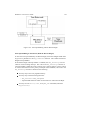
WinDriver USB Architecture
Figure 2.3: WinDriver USB Architecture
To access your hardware, your application calls the required WinDriver USB API
function from the WinDriver user mode Library (windrvr.h). The user mode Library
calls the WinDriver Kernel module, windrvr.sys. The WinDriver Kernel module
accesses your USB device resources through the native operating system calls.
There are two layers responsible to abstract the USB device to the USB device driver:
The upper one is the USB Driver layer (including the USB Driver (USBD) and
USB Hub Driver) and the lower one is the Host Controller Driver layer (HCD). The
division of duties between the host controller driver and USB driver is not defined,
46
2 WinDriver USB Overview
and is operating system dependent. Both host controller driver and USB driver are
software interfaces and components of the operating system, where the host controller
driver layer represents a lower level of abstraction.
The host controller driver is the software layer that provides an abstraction of the host
controller hardware while the USBD provides an abstraction of the USB device and
the data transfer between the host software and the function of the USB device.
The USBD communicates with its clients (the specific device driver for example)
through the USB Driver Interface (USBDI). At the lower level, the USB driver and
USB hub driver implement the hardware access and data transfer by communicating
with the HCD using the host controller driver interface.
The USB hub Driver is responsible for identifying addition and removal of devices
from a particular hub. Once the Hub Driver receives a signal that a device was
attached or detached, it uses additional host software and the USB driver to recognize
and configure the device. The software implementing the configuration can include
the hub driver, the device driver and other software.
WinDriver USB abstracts the configuration procedure and hardware access described
above for the developer. With WinDriver USB API, developers can do all the hardware
related operations without having to master the lower levels of implementing these
activities.
2.10
Which Drivers Can I Write with WinDriver
USB?
Almost all monolithic drivers (drivers that need to access specific USB devices),
can be written with WinDriver USB. In cases where a standard driver needs to be
written, e.g., NDIS driver, SCSI driver, Display driver, USB to Serial port drivers,
USB layered drivers, etc., use KernelDriver USB (also from Jungo).
For quicker development time, select WinDriver USB over KernelDriver USB
wherever possible.
Chapter 3
Installation and Setup
This chapter takes you through the WinDriver installation process, and shows you
how to verify that your WinDriver is properly installed. The last section discusses
the uninstallation procedure.
3.1
3.1.1
System Requirements
For Windows 95 / 98 / Me
An x86 processor.
Any 32-bit development environment supporting C, VB or Delphi.
3.1.2
For Windows NT / 2000 / XP
An x86 processor.
Any 32-bit development environment supporting C, VB or Delphi.
Windows NT: Required at least Service Pack 3. Recommended: Service Pack
6.
47
3 Installation and Setup
48
3.1.3
For Windows CE
An x86 Windows CE target platform.
Windows NT/2000/XP host development platform.
Microsoft eMbedded Visual C++ with a corresponding target SDK
or
Microsoft Platform Builder with corresponding BSP (Board Support Package)
for the taget platform.
3.1.4
For Linux
WinDriver supports all versions of Linux from 2.0.31 and above, including
embedded Linux and Linux 2.4x.
An x86 processor.
Any 32-bit development environment supporting C (such as GCC).
3.1.5
For Solaris
WinDriver supports Solaris 2.6/7.0/8.0, for both Sparc and Intel x86 platforms.
Any 32-bit development environment supporting C (such as GCC).
3.1.6
For VxWorks
Windows host development platform.
Tornado II IDE.
Selected Target Platform: This should be running a processor that has a BSP
(Board Support Package) compatible with the list of CPU/BSP combinations
supported by DriverBuilder.
For an up-to-date list, see the URL below:
http://www.jungo.com/db- vxworks.html#platforms
For information on BSP compatibility, please contact your nearest WindRiver
Systems support representative.
WinDriver 5.22 User’s Guide
3.2
49
Installing WinDriver
The WinDriver CD contains all versions of WinDriver for all the different operating
systems. The CD’s root directory contains the Windows 95/98/Me and NT/2000/XP
version. This will automatically begin when you insert the CD into your CD drive.
The other versions of WinDriver are located in subdirectories i.e., \Linux, \Wince
and so on.
3.2.1
Installing WinDriver for Windows 95, 98, Me, NT, 2000
and XP
NOTE:
You must have administrative privileges in order to install WinDriver on Windows
95, 98, Me, NT, 2000 and XP.
1. Insert the WinDriver CD into your CD-ROM drive.
(When installing WinDriver by downloading it from Jungo’s web site instead
of using the WinDriver CD, double click the downloaded WinDriver file
(WDxxx.EXE) in your download directory, and go to step 3).
2. Wait a few seconds until the installation program starts automatically. If for
some reason it does not start automatically, double-click the file Wdxxx.EXE
(where xxx is the version number) and click the Install WinDriver button.
3. Read the license agreement carefully, and click Yes if you accept its terms.
4. Choose the destination location in which to install WinDriver.
5. In the Setup Type screen, choose one of the following:
Typical - To install all WinDriver modules. (Generic WinDriver toolkit +
specific chipset APIs).
Compact - To install only the generic WinDriver toolkit.
Custom - To choose which modules of WinDriver to install. You may
choose which APIs will be installed.
6. After the installer completes copying all the required files, chose whether to
view the quick-start guides.
7. You may now be prompt to reboot your computer.
3 Installation and Setup
50
The Following Steps are for Registered Users Only:
In order to register your copy of WinDriver with the license you have received from
Jungo, please follow the steps bellow:
1. Activate DriverWizard GUI (Start | Programs | WinDriver |
DriverWizard).
2. Select the Register WinDriver option from the File menu and insert the
license string you received from Jungo there. Press Activate License button.
3. To activate source code you have developed during the evaluation period, please
refer to WD_license function refence.
3.2.2
Installing WinDriver CE
The installation instructions for WinDriver CE differ depending on what you want to
do with Windows CE. There are two types of CE development tasks 1. "Building" new CE based platforms.
This will usually be the case if you are an OEM who ports the Windows CE
operating system to his custom hardware using Microsoft Platform Builder (for
example, if you are developing a device like a Pocket PC or a Handheld PC).
2. Developing applications for Windows CE based computers.
This will usually be the case if you are an ISV (independent software vendor)
who develops applications, using Microsoft eMbedded Visual Tools, targeted
to run on CE platforms created by the OEMs.
Installing WinDriver CE when "building" new CE based platforms
NOTE:
It is highly recommended that you read Microsoft’s documentation and understand
the Windows CE and device driver integration procedure before you perform the
Installation.
1. Run Microsoft Platform Builder and open your platform.
2. Select Open Build Release Directory in the Build menu.
WinDriver 5.22 User’s Guide
51
3. Copy the WinDriver CE kernel file
\WinDriver\redist\TARGET_CPU\windrvr.dll
to the %_FLATRELEASEDIR% subdirectory on your development platform
(should be the current directory in the new command window).
4. Append the contents of the file
\WinDriver\samples\wince_install\PROJECT_WD.REG
to the file PROJECT.REG in the %_FLATRELEASEDIR% subdirectory.
5. Append the contents of the file
\WinDriver\samples\wince_install\PROJECT_WD.BIB
to the file PROJECT.BIB in the %_FLATRELEASEDIR% subdirectory.
This step is only necessary if you want the WinDriver CE kernel file
(WINDRVR.DLL) to be part of the Windows CE image (NK.BIN)
permanently. This would be the case if you were transferring the file to
your target platform using a floppy disk. If you prefer to have the file
WINDRVR.DLL loaded on demand via the CESH/PPSH services, you need
not carry out this step until you build a permanent kernel.
6. Select Make Image in the Build menu called NK.BIN.
7. Download your new kernel to the target platform and initialize it (e.g., select
Download / Initialize in the Target menu or by using a floppy disk).
8. Restart your target CE platform. The WinDriver CE kernel will automatically
load.
9. Compile and run the sample programs (see Section 3.4 that describes how
to check your installation) to make sure that WinDriver CE is loaded and is
functioning correctly.
Installing WinDriver CE when developing applications for CE computers
1. Insert the WinDriver CD into your Windows host CD drive.
2. Exit from the auto installation.
3. Double click the Cd_setup.exe file from the \Wince directory inside the CD.
This will copy all needed WinDriver files to your host development platform.
4. Copy the WinDriver CE kernel file
\WinDriver\redist\TARGET_CPU\windrvr.dll
to the \WINDOWS subdirectory of your target CE computer.
3 Installation and Setup
52
5. Use the Windows CE Remote Registry Editor tool (ceregedt.exe) or the
Pocket Registry Editor (pregedt.exe) on your target CE computer to modify
your registry so that the WinDriver CE kernel is loaded appropriately. The
file \WinDriver\samples\wince_install\PROJECT_WD.REG contains the
appropriate changes to be made.
6. Restart your target CE computer. The WinDriver CE kernel will automatically
load. You will have to do a warm reset rather than just suspend/resume (use the
reset or power button on your target CE computer).
7. Compile and run the sample programs (see Section 3.4 that describes how
to check your installation) to make sure that WinDriver CE is loaded and is
functioning correctly.
3.2.3
Installing WinDriver for Linux
Preparing the System for Installation
In Linux, Kernel modules must be compiled with the identical header files that
the kernel itself was compiled with. Since WinDriver installs the Kernel module
windrvr.o, it must compile with the header files of the Linux kernel during the
installation process.
Therefore, before you install WinDriver for Linux, verify that the Linux source code
and the file versions.h are installed on your machine:
Install linux kernel source code
If you have yet to install Linux, please choose Custom installation when
performing the installation and then choose to install the source code.
If Linux is already installed on the machine, you must check to see if the Linux
source code was installed. You can do this by looking for linux in the /usr/src
directory. If the source code is not installed, you can either reinstall Linux
with the source code, as described above, or you can install the source code by
following these steps:
1. Login as super user.
2. Type:
/$ rpm -i /<source location>/ <Linux
distributor>/RPMS/kernel-source-<version number>
WinDriver 5.22 User’s Guide
53
(For example: to install the source code from the Linux installation
CD-Rom, for RedHat 7.1, type:
/$ rpm -i /mnt/cdrom/RedHat/RPMS/
kernel-source-2.4.2.-2.i386rpm)
TIP!
If you do not have a RPM with the source code you may download it
from the following link: http://rpmfind.net/linux/RPM/.
Install version.h
The file version.h is created when you first compile the Linux kernel source
code. Some distributions provide a compiled kernel without the file version.h.
Look under /usr/src/linux/include/linux/ to check if you have this file. If you
do not, please follow these steps:
1. Type:
/$ make xconfig
2. Save the configuration by choosing Save and Exit.
3. Type:
/$ make dep.
Before proceeding with the installation, you must also make sure that you have a
linux symbolic link. If you do not, please create one by typing:
/usr/src$ ln -s <target kernel>/ linux
(For example: for Linux 2.4 kernel type:
/usr/src$ ln -s linux-2.4/ linux)
Installation
1. Insert the WinDriver CD into your Linux machine CD drive or copy the
downloaded file to your preferred directory.
2. Change directory to your preferred installation directory (for example, your
home directory):
/$ cd ~
3. Extract the file WDxxxLN.tgz (where xxx is the version number):
~$ tar xvzf /<file location>/WDxxxLN.tgz
For example:
3 Installation and Setup
54
From a CD:
~$ tar xvzf /mnt/cdrom/LINUX/WDxxxLN.tgz
From a downloaded file:
~$ tar xvzf /home/username/WDxxxLN.tgz
4. Change directory to WinDriver (this directory gets created by tar):
~$ cd WinDriver/
NOTE:
In V5.x, this directory gets created by tar, but in versions preceding 5.x, the
WinDriver directory does not get created by the extraction. Therefore when
working with versions preceding 5.x (for example: version 4.33), first create
a directory (e.g., WinDriver) before proceeding with the installation.
(/$ mkdir ~/WinDriver)
5. Install WinDriver:
(a) ~/WinDriver$ make
(b) Become super user:
~/WinDriver$ su
(c) Install the driver:
~/WinDriver# make install
6. Create a symbolic link so that you can easily launch the DriverWizard GUI
~/WinDriver$ ln -s ~/WinDriver/wizard/wdwizard/
usr/bin/wdwizard
7. Change the read and execute permissions on the file wdwizard so that ordinary
users can access this program.
8. Change the user and group ids and give read/write permissions to the device file
/dev/windrvr depending on how you wish to allow users to access hardware
through the device.
9. You can now start using WinDriver to access your hardware and generate your
driver code!
The Following Steps are for Registered Users Only
In order to register your copy of WinDriver with the license you have received from
Jungo, please follow the steps bellow:
WinDriver 5.22 User’s Guide
55
1. Activate the DriverWizard GUI:
~/WinDriver/wizard$ ./wdwizard
2. Select the Register WinDriver option from the File menu and insert the
license string you received from Jungo.
3. Press Activate License button.
4. To register source code you have developed during the evaluation period, please
refer to WD_License function reference in section A.1.9.
Restricting Hardware Access on Linux
CAUTION:
Since /dev/windrvr gives direct hardware access to user programs, it may
compromise kernel stability on multi-user Linux systems. Please restrict access to
the DriverWizard and the device file /dev/windrvr to trusted users.
For security reasons the WinDriver installation script does not automatically perform
the steps of changing the permissions on /dev/windrvr and the DriverWizard
executable (wdwizard).
3.2.4
Installing WinDriver for Solaris
Since WinDriver installation installs the Kernel module windrvr.o, it should be
installed by the system administrator logged in as root, or with root privileges.
1. Insert your CD into your Solaris machine CD drive or copy the downloaded file
to your preferred directory.
2. Change directory to preferred installation directory, (for example, your home
directory):
/$ cd ~
3. Copy the file WDxxxSLS.tgz (Sparc) or WDxxxSL.tgz (Intel) to the current
directory (here "xxx" stands for the version number, for example 500):
~$ cp /home/username /WDxxxSL.tgz /
NOTE:
When installing WinDriver for Solaris x86 use WDxxxSL.tgz instead of
WDxxxSLS.tgz.
3 Installation and Setup
56
4. Extract the file:
~$ gunzip -c WDxxxSLS.tgz | tar -xvf WDxxxSLS.tar
5. Change directory to WinDriver.
CAUTION:
In V5.x this directory gets created by tar but in versions preceding 5.x,
the WinDriver directory does not get created by the extraction. Therefore
with older versions like 4.3, first create a directory (say WinDriver) before
proceeding with the installation.
6. Install WinDriver for Solaris
~/WinDriver$ ./ install_windrvr
7. Create a symbolic link so that you can easily launch the DriverWizard GUI
~/WinDriver$ ln -s ~/WinDriver/wizard/wdwizard
/usr/bin/wdwizard
8. Change the read and execute permissions on the file wdwizard so that ordinary
users can access this program
9. Change the user and group ids and give read/write permissions to the device file
/dev/windrvr depending on how you wish to allow users to access hardware
through the device.
10. You can now start using WinDriver to access your hardware and generate your
driver code!
The Following Steps are for Registered Users Only:
In order to register your copy of WinDriver with the license you have received from
Jungo, please follow the steps bellow:
1. Activate the DriverWizard GUI
~/WinDriver/wizard$ ./wdwizard
2. Select the Register WinDriver option from the File menu and insert the
license string you received from Jungo.
3. Press Activate License button.
4. To register source code you have developed during the evaluation period, please
refer to WD_License function reference in section A.1.9.
WinDriver 5.22 User’s Guide
57
Restricting Hardware Access on Solaris
CAUTION:
Since /dev/windrvr gives direct hardware access to user programs, it may
compromise kernel stability on multi-user Solaris systems. Please restrict to
trusted users, access to DriverWizard and the device file /dev/windrvr.
For security reasons the WinDriver installation script does not automatically perform
the steps of changing the permissions on /dev/windrvr and the DriverWizard
executable (wdwizard).
Solaris Platform Specific Issues
WinDriver for Solaris supports version 2.6, 7.0 and 8.0 on Intel X86 and Sparc.
The same WinDriver based hardware access code will run on both platforms after
recompilation.
WinDriver does not support Solaris 7.0 or 8.0 64 bit kernel. To switch from a 64 bit
kernel to a 32 bit kernel follow these simple steps:
1. Reboot the computer (as super user)
/# -#reboot
2. When the computer resets, Break into the boot prompt by pressing
STOP+A
3. At the prompt enter the following:
/# boot kernel/unix
4. To make the 32 bit kernel to be the default one, enter the following at the boot
prompt:
/# setenv boot-file kernel/unix
3.2.5
Installing DriverBuilder for VxWorks
The following describes the installation of DriverBuilder for VxWorks. DriverBuilder
development environment works with Tornado 2 for Windows only (on x86 platform).
Drivers generated using version 5.x of DriverBuilder will run on Intel x86 BSPs
(pc486, pcPentium and pcPentiumPro), PPC 821/860 with MBX821/860 and PPC
750 (IBM PPC 604) with MCP750. For an up-to-date list, see the URL below:
http://www.jungo.com/db- vxworks.html#platforms.
Installation:
3 Installation and Setup
58
1. Download DriverBuilder for VxWorks.
2. Change drive to the preferred root drive for DriverBuilder, for example:
\> c:\
3. Unpack the file you downloaded:
\> unzip -d DBXXXVX.zip c:\ (here "xxx" stands for the version
number, for example 500.)
NOTE:
The extraction creates a directory called DriverBuilder under which all the
DriverBuilder installation files can be found.(this feature was added in version
5.00. If you are working on a previous version, please create a directory for
DriverBuilder, for example:
\> c:\cd_vxworks and unpack the file to it:
\> unzip -d DBxxxVX.zip c:\db_vxworks
NOTE:
The WinDriver samples for VxWorks have the .out extension. For example,
pci_diag.out. To invoke these programs, use Windsh to load them, and execute the
routine xxx_main. For example:
wddebug.out : wddebug_main pci_diag.out : pci_diag_main
TIP!
DriverBuilder is based on Jungo’s WinDriver product line. You may save much
time by downloading the Windows version of WinDriver and use its graphical
development environment for fast hardware validation and automatic code
generation. If you choose to do so - Please follow the next few steps:
1. Download and install DriverBuilder for VxWorks.
2. Download and install WinDriver for Windows (Don’t skip this part).
3. Create a shortcut on your desktop to DriverWizard found under
C:\WinDriver\wizard\wdwizard.exe so that you can easily launch and
develop your driver using the GUI DriverWizard.
WinDriver 5.22 User’s Guide
3.3
59
Upgrading Your Installation
To upgrade to a new version of WinDriver on Windows, follow the steps outlined
in Section 3.2.1 that illustrates the process of installing WinDriver for Windows
95/98/Me/NT/2000/XP. You can either choose to overwrite the existing installation or
install to a separate directory.
After installation, start DriverWizard and enter the new license string, if you have
received one. This completes the upgrade of WinDriver.
To upgrade your source code, pass the new license string as a parameter to
WD_License, please refer to WD_License function reference in section A.1.9 for
more details.
The procedure for upgrading your installation on other operating systems is the same
as the one described above. Please check the respective installation sections for
installation details.
3.4
3.4.1
Checking Your Installation
On Your Windows Machine
1. Start DriverWizard by choosing Programs |WinDriver | DriverWizard from
the Start menu.
Registered Users
1. Make sure that your WinDriver license is installed (see Section 3.2 that explains
how to install WinDriver). If you are an evaluation version user, you do not
need to install a license.
2. For PCI cards - Insert your card into the PCI bus, and verify that DriverWizard
detects it.
3. For ISA cards - Insert your card into the ISA bus, configure DriverWizard with
your card’s resources and try to read / write to the card using DriverWizard.
3 Installation and Setup
60
3.4.2
On Your Windows CE Machine
1. Start DriverWizard on your Windows host machine by choosing Programs |
WinDriver | DriverWizard from the Start Menu.
2. Make sure that your WinDriver license is installed. If you are an evaluation
version user, you do not need to install a license.
3. For PCI devices - Plug in your device to the computer, and verify that
DriverWizard detects it.
4. For ISA cards - Insert your card into the ISA bus, Configure DriverWizard with
your card’s resources and try to read / write to the card using DriverWizard.
5. Activate Visual C++ for CE.
6. Load one of the WinDriver samples
\WinDriver\samples\speaker\speaker.dsw).
(e.g.,
7. Select the target platform as X86em from the Visual C++ WCE configuration
toolbar.
8. Compile and run the speaker sample. The Windows host machine’s speaker
should be activated from within the CE emulation environment.
NOTE:
ISAPnP is not supported under Windows CE.
3.4.3
On Your Linux Machine
1. Run the pre-compiled speaker sample found in
WinDriver/samples/speaker/LINUX/speaker.
If the sample program works, then you have installed WinDriver for Linux
properly.
3.4.4
On Your Solaris Machine
1. Run the precompiled speaker sample found in
WinDriver/samples/speaker/Solaris/speaker.
If the sample program works, then you have installed WinDriver for Solaris
properly (this program only works under X86). For Sparc Solaris you can run
the GUI DriverWizard to check the installation.
WinDriver 5.22 User’s Guide
3.4.5
61
On VxWorks
1. In x86 only: Make sure MMU is set to basic support
(hardware/memory/MMU/MMU Mode).
2. Load DriverBuilder, download the object file:
(DriverBuilder \redist\eval\intelx86\PENTIUM\windrvr.o).
3. Initialize DriverBuilder, from the WindShell:
=> drvrInit()
function returned (return value = 0)
=>
4. Run
a
sample
driver,
load: C:\DriverBuilder \samples\pci_diag\PENTIUM\pci_diag.out from
the WindShell:
=> pci_diag_main()
5. Scan the PCI bus, open cards and access them.
3.5
Uninstalling WinDriver
If for some reason you wish to uninstall either the evaluation or registered version of
WinDriver, please refer to this section.
3.5.1
Uninstalling WinDriver from Windows 95, 98, Me, NT,
2000 and XP
1. From a command line application call:
\> cd WinDriver\util
\WinDriver\util> wdreg remove
2. Uninstall WinDriver using the uninstall shield:
Start | Settings | Control Panel | add/remove programs
3 Installation and Setup
62
3. Erase the following files if they still exist:
WinNT + Win2000 + WinXP: \winnt\system32\drivers\windrvr.sys
Win95 + Win98 + Win Me: \Windows\system\vmm32\windrvr.vxd
Win98 + Win Me: \Windows\system32\drivers\windrvr.sys
4. Erase your Kernel PlugIn driver - if you have developed such. It should exist in
the same directory as windrvr.sys/vxd.
5. Erase the directory (\windriver) it was in.
6. Erase it’s entry in the start menu:
Start | Settings | Task Bar | start menu programs | advanced | all users |
start menu | programs | windriver
7. Erase the VB dll file:
WinNT + Win2000 + WinXP: \winnt\system32\Wd_vb.dll
Win95 + Win98 + Win Me: \Windows\system32\Wd_vb.dll
8. Reboot the computer.
3.5.2
Uninstalling WinDriver from Linux
CAUTION:
You must be logged in as root to do the uninstallation.
1. Uninstall the WinDriver service, do a
/# /sbin/lsmod
to check if the WinDriver module is in use by any application or by other
modules.
2. Make sure that no programs are using WinDriver.
3. If any application or module is using WinDriver, close all applications and do a
/sbin# rmmod
to remove any module using WinDriver
4. Run the command:
/sbin# rmmod windrvr.
WinDriver 5.22 User’s Guide
63
5. /# rm -rf /dev/windrvr (Remove the old device node in the /dev
directory)
6. If you have created a Kernel PlugIn - Remove your kernel PlugIn driver as well.
7. Remove the file .windriver.rc in the /etc directory:
/# rm -rf /etc/.windriver.rc
8. Remove the file .windriver.rc in $HOME:
/# rm -rf $HOME/.windriver.rc
9. If you created a symbolic link to DriverWizard, delete the link using the
command:
/# rm -f /usr/bin/wdwizard
10. Delete the WinDriver installation directory. Use the command:
/# rm -rf ~/WinDriver
3.5.3
Uninstalling WinDriver from Solaris
CAUTION:
You must be logged in as root to do the uninstallation.
1. Uninstall the WinDriver service.
2. Make sure no programs are using WinDriver.
3. If any applications or modules are using WinDriver, then close them and do a
/usr/sbin# rem_drv
to remove any modules using WinDriver.
4. Run the command:
/usr/bin# rem_drv windrvr
to unload the Kernel module
5. Run the command:
/# rm -rf /kernel/drv/windrvr
/kernel/drv/windrvr.conf
to clean up the old device node.
6. If you have created a Kernel PlugIn - Remove your kernel PlugIn driver as well.
3 Installation and Setup
64
7. Remove the file .windriver.rc in the /etc directory, to do this run the command:
/# rm -rf /etc/.windriver.rc
8. Remove the file .windriver.rc in $HOME, to do this run the command:
/# rm -rf $HOME/.windriver.rc
9. If you created a symbolic link to DriverWizard, delete the link using the
command:
/# rm -f /usr/bin/wdwizard.
10. Delete the WinDriver installation directory. Use the command:
/# rm -rf ~/WinDriver.
3.5.4
Uninstalling DriverBuilder for VxWorks
1. Delete the DriverBuilder installation directory (for example:
C:\DriverBuilder) using Windows Explorer
2. If you created any shortcuts to DriverWizard on your desktop, delete the
shortcut.
Chapter 4
Using DriverWizard
4.1
An Overview
DriverWizard (included in the WinDriver toolkit) is a GUI based diagnostics and
driver generation tool that allows you to write to and read from the hardware, before
writing a single line of code. The hardware is diagnosed through a Graphical User
Interface - Memory ranges are read, registers are toggled and interrupts are checked.
Once the card is operating to your satisfaction, DriverWizard creates the skeletal
driver source code, with functions to access all your hardware resources.
If you are developing a driver for a card which is based on one of the supported
USB or PCI chipsets (Cypress / National Semiconductors / PLX / Altera / Marvell
/ PLDA / AMCC and QuickLogic), it is recommended you read chapter 7 that
explains WinDriver’s enhanced support for specific chipsets, before starting your
driver development.
DriverWizard can be used to diagnose your hardware and can generate an INF file
for hardware running under Windows 95/98/Me/2000/XP (An INF file should not be
generated for hardware running under Windows NT). Avoid using DriverWizard to
generate code for a card based on one of the supported PCI chipsets, as DriverWizard
generates generic code which will have to be modified according to the specific
functionality of the card at hand. Preferably, use the complete source code libraries
and sample applications (supplied in the package) tailored for the various PCI
chipsets.
DriverWizard is an excellent tool for two major phases in your HW / Driver
development:
65
4 Using DriverWizard
66
Hardware diagnostics: After the hardware has been built, insert the hardware into
the appropriate slot (PCI/CardBus/ISA/ISAPnP/EISA/CompactPCI) or attach
your USB device to the USB port in your machine, and use DriverWizard to
verify that the hardware is performing as expected.
Code generation: Once you are ready to build your code, let DriverWizard generate
your driver code for you.
The code generated by DriverWizard is composed of the following elements:
Library functions for accessing each element of your device’s resources (memory
ranges, I/O ranges, registers and interrupts).
A 32 bit diagnostics program in console mode with which you can diagnose your
device. This application utilizes the special library functions described above.
Use this diagnostics program as your skeletal device driver.
A project workspace that you can use to automatically load all of the project
information and files into your development environment. In WinDriver Linux
and WinDriver Solaris, DriverWizard generates the makefile for the relevant
operating system.
4.2
DriverWizard Walkthrough
Following are the steps in using DriverWizard:
1. Plug your hardware to the computer:
If it’s a PCI/CardBus/ISA/ISAPnP/EISA/CompactPCI card, plug it into the
appropriate slot in your computer; If it’s a USB device, plug it into the USB
port in your computer.
2. Run DriverWizard and select your device:
(a) Click Start | Programs | WinDriver | DriverWizard or double click
the DriverWizard icon on your desktop.
(b) Press OK on the initial screen.
(c) Press Next in the Choose Your Project dialog box.
(d) Select your PnP Device from the list of devices detected by DriverWizard
(for non PnP cards select ISA).
WinDriver 5.22 User’s Guide
67
Figure 4.1: Selection of PnP Device
NOTE:
On Windows 98, if you do not see your USB device in the list, reconnect
it and make sure the New Hardware Found/Add New Hardware wizard
appears for your device. Do not close the dialog box until you have generated
and INF for your device using the steps below.
3. Generate an INF file for DriverWizard:
In some cases you will need to generate an INF file to enable DriverWizard
to diagnose your device (for example, when no driver is installed for your
PCI / USB device). This is only required when using WinDriver to support
a Plug-and-Play device (PCI/USB) on a Plug-and-Play system (Windows
98/Me/2000/XP). The need for an INF file in certain situations is explained in
section 13.4.1.
DriverWizard automates this process for you and will notify you if you need to
generate an INF file: If you clicked Next in the previous step and no such
notice appeared, skip this step and proceed to the next one.
To generate the INF file with the DriverWizard follow the steps below:
(a) In the Select Your Device screen, click the Generate .INF file button or
click Next.
68
4 Using DriverWizard
(b) In the dialog box that appears, fill in the required details:
Figure 4.2: DriverWizard INF File Information
NOTE:
For USB devices with multiple interfaces, you must indicate all the
interfaces supported, so that DriverWizard will work properly.
(c) When you’re done, click Next and choose the directory in which you
wish to store the generated INF file. DriverWizard will then automatically
generate the INF file for you.
On Windows 2000/XP you can select to automatically install the INF file
from the DriverWizard, by checking the Automatically Install the INF
file option in the DriverWizard’s INF generation dialog box. On Windows
98/Me you must install the INF file manually, using Windows Add New
Hardware Wizard or Upgrade Device Driver Wizard, as explained in
section 13.4. If the automatic INF file installation on Windows 2000/XP
WinDriver 5.22 User’s Guide
69
fails, DriverWizard will notify you and provide manual installation
instructions for this OS as well.
(d) When the INF file installation completes, select and open your device
from the list in the Select Your Device screen.
4. Select your USB device’s alternate setting:
(This step is for USB devices only. Developers working with
PCI/CardBus/ISA/ISAPnP/EISA/CompactPCI cards should skip this step).
Choose the desired alternate setting from the list. (Note that DriverWizard
reads all the supported devices’ alternate settings and displays them. For USB
devices with only one alternate setting configured, DriverWizard automatically
selects the detected alternate setting and therefore the Select Device Interface
dialog-box will not be displayed).
5. Diagnose your device:
Before writing your device driver, it is important to make sure your hardware
is working as expected. Use DriverWizard to diagnose your hardware. All of
your activity will be logged in the DriverWizard Log, so that you may later
analyze your tests:
Define and test your PCI device’s I/O and memory ranges, registers and
interrupts.
– DriverWizard will automatically detect your Plug-n-Play hardware’s
resources (I/O ranges, Memory ranges and Interrupts). You can
define the registers manually.
– For non Plug-n-Play hardware - define your hardware’s resources
manually.
– Read and write to the I/O ports, memory space and your defined
registers.
– "Listen" to your hardware’s interrupts.
Test your USB device’s pipes.
– DriverWizard shows the pipe detected according to the selected
configuration\interface\alternate setting.
In order to perform USB data transfers follow the steps given below:
(a) Select the desired pipe.
(b) For a control pipe (a bi-directional pipe) - press Read / Write
to Pipe. A new dialog will appear, allowing you to enter a
setup packet and write operation data. The setup packet should
70
4 Using DriverWizard
Figure 4.3: USB Device Configuration
be 8 bytes long (little endian) and should conform to the USB
specification parameters (bmRequestType, bRequest, wValue,
wIndex, wLength).
NOTE:
More detailed information on how to implement the control
transfer and how to send setup packets can be found under
Chapter 8.
(c) For an input pipe (moves data from device to the host) - click
Listen to Pipe. To successfully accomplish this operation with
devices other than HID, first you need to verify that the device
WinDriver 5.22 User’s Guide
71
Figure 4.4: A PCI Diagnostics Screen
sends data to the host. If no data is being sent, after listening
for a short period of time DriverWizard will notify you that the
Transfer Failed.
(d) To stop reading click: Stop Listen to Pipe.
(e) For an output pipe (host to device) - press Write to Pipe. A new
dialog will appear, asking you to enter the data to write. The
DriverWizard Log will contain the result of the operation.
6. Generate the skeletal driver code:
(a) Select Generate Code from the Build menu, or press Next from the
Define and Test Resources for Your Device dialog.
(b) Select WinDriver from the Choose Type of Driver dialog-box.
Selecting the KernelDriver option will generate kernel source
code designed for full kernel mode drivers. See the KernelDriver
documentation or the Jungo web site (http://www.jungo.com)
for more details. (Note that this dialog-box appears only when both
WinDriver and KernelDriver are installed on your machine).
72
4 Using DriverWizard
Figure 4.5: USB Diagnostics Screen
Figure 4.6: Generate Code Option
(c) Next, the Select Code Generation Options dialog box will appear.
Choose the language in which the code will be generated and the desired
development environment for the various operating systems.
(d) Press Next and indicate if you wish to handle Plug-and-Play and power
management events from within your driver code and if you wish to
generate Kernel PlugIn code:
NOTE:
In order to work with a Kernel PlugIn, you must have an appropriate
Microsoft DDK installed on your computer before you generate Kernel
PlugIn code.
(e) Press Next and if required generate and install an INF file for your device,
WinDriver 5.22 User’s Guide
73
Figure 4.7: Select Driver Type
as described in step 7 below. (If after pressing the Next button no message
regarding INF file generation appears, proceed to step 8).
(f) Save your project (if required) and press OK to open your development
environment with the generated driver.
7. Generate an INF file for your device:
This step resembles step #3 above. However the INF file you generate
here is designed for the final driver you create, and not for enabling the
DriverWizard to access the device, as in the INF installation in step #3
above.
Whenever developing a driver for a Plug-and-Play Windows operating
system (i.e., Windows 98, Me, 2000 or XP) you are required to install an
INF file for your device. This file will register your Plug-and-Play device
to work with the windrvr.sys driver. The need for creating an INF file
4 Using DriverWizard
74
Figure 4.8: Options for Generating Code
Figure 4.9: Notification Events
is explained in section 13.4.1. The file generated by the DriverWizard
in this step should later be distributed to your customers, who are using
Windows 98/Me/2000/XP, and installed on their PCs.
To generate an INF file for your device, follow the DriverWizard
instructions:
WinDriver 5.22 User’s Guide
75
(a) DriverWizard will prompt you for information about your device:
Vendor ID, Device/Product ID, Device Class, etc.
Figure 4.10: INF Generation
NOTE:
For USB devices with multiple interfaces, you must indicate all the
interfaces supported by your driver in order for your driver to work
properly.
(b) Press Next to generate the INF file.
8. Compile and run the generated code:
Use this code as a starting point for your device driver. Modify where
needed to perform your driver’s specific functionality.
The source code DriverWizard creates can be compiled with any
32-bit compiler, and will run on all supported platforms (Windows
95/98/Me/NT/2000/XP/CE, Linux, Solaris and VxWorks) without
modifications.
4 Using DriverWizard
76
4.3
4.3.1
DriverWizard Notes
Sharing a Resource
If you want more than one driver to share a single resource, you must define that
resource as shared:
1. Select the resource.
2. Right click on the resource.
3. Select Share from the menu.
NOTE:
New interrupts are set as Shared by default. If you wish to define an interrupt as
unshared, follow steps 1 and 2, and select Unshared in step 3.
4.3.2
Disabling a Resource
During your diagnostics, you may wish to disable a resource, so that DriverWizard
will ignore it, and not create code for it.
1. Select the resource.
2. Right click on the resource name.
3. Choose Disable from the menu.
4.3.3
DriverWizard Logger
DriverWizard Logger is the empty window that opens up along with the Device
Resources dialog box when opening a new project. The logger keeps track of all
of the input / output during the diagnostics stage, so that the developer may analyze
his device’s physical performance at a later time. You can save the log for future
reference. When saving the project, your log is saved as well. Each log is associated
with one project.
WinDriver 5.22 User’s Guide
4.3.4
77
Automatic Code Generation
After you have finished diagnosing your device and have ensured that it runs according
to your specifications, you are ready to write your driver.
Generating the Code
Choose Generate Code from the Build menu. DriverWizard will generate the source
code for your driver, and place it along with the project file (xxx.wdp, where "xxx"
is the project name). The files are saved in a directory DriverWizard creates for
every development environment and operating system chosen in the Generate Code
dialog-box.
In the source code directory you now have a new xxxlib.h file which states the
interface for the new functions that DriverWizard created for you, and the source of
these functions, xxxlib.c, where your device-specific API is implemented. In addition,
you will find the sample function main in the file xxxdiag.c.
The code generated by DriverWizard is composed of the following elements and files
("xxx" your project name):
Library functions for accessing each element of your card’s resources (memory
ranges, I/O ranges, registers, interrupts and the USB pipes):
xxx_lib.c here you can find the implementation of the hardware-specific API
(found in xxx_lib.h), using the regular WinDriver API.
xxx_lib.h this is the header file of the diagnostics program. Here you can find
the hardware-specific API created by DriverWizard. You should include
this file in your source code in order to use this API.
A general PCI utility library:
A diagnostics program - Which is a console application with which you can
diagnose your card. This application utilizes the special library functions,
which were created for your device by DriverWizard. Use this diagnostics
program as your skeletal device driver.
pci_diag_lib.c This is the source code of the diagnostics program
DriverWizard creates.
A list of all files created can be found at xxx_files.txt.
After creating your code, compile it with your favorite Win32 compiler, and see it
work!
Change the function main of the program so that the functionality fits your needs.
4 Using DriverWizard
78
Compiling the Generated Code
For Windows 95, 98, Me, NT, 2000, XP and CE (Using MSDEV):
1. For Windows platforms, DriverWizard generates the project files (for MSDEV
4, 5 and 6 , Borland C/C++ Builder and Delphi 2, 3, 4, 5). After code
generation, the chosen IDE (Integrated Development Environment) will be
launched automatically. You can then immediately compile and run the
generated code.
For Linux and Solaris:
1. DriverWizard creates a makefile for your project.
2. Compile the source code using the makefile generated by DriverWizard.
3. Use GCC to build your code.
For Other OSs or IDEs:
1. Create a new project in your IDE (Integrated development environment).
2. Include the source files created by DriverWizard into your project.
3. Compile and run the project.
4. The project contains a working example of the custom functions that
DriverWizard created for you. Use this example to create the functionality
you want.
Chapter 5
Developing a Driver
This chapter takes you through the WinDriver driver development cycle.
NOTE:
If your PCI bridge or USB controller is either a PLX / Altera / PLDA / Marvell
/ Quicklogic / AMCC / Cypress, then WinDriver provides a special set of APIs
customized for these chipsets that further shortens your development time. If this is
the case, read the following overview and then jump straight to Chapter 7.
5.1
Using the DriverWizard to Build a Device Driver
Use DriverWizard to diagnose your card. Read / write to the IO / memory
ranges / registers that your card supports and to the pipes of your USB device.
Verify that your device operates as expected.
Use DriverWizard to generate skeletal code for your device in C, C++ or
Delphi. Refer to Chapter 4 for details about DriverWizard.
If you are using one of the supported chipsets (PLX / Altera / PLDA /
Marvell / Quicklogic / AMCC / Cypress) as your USB or PCI bridge
– It is recommended that you use the source code of p9030_diag.exe
| p9054_diag.exe | p9050_diag.exe | p9080_diag.exe | p9060_diag.exe
| iop480_diag.exe | p480_diag.exe | gt64_diag.exe | amccdiag.exe |
pbc_diag.exe | altera_diag.exe | download_sample.exe | bulk_diag.exe
79
5 Developing a Driver
80
(according to your chipset) as your skeletal driver code. These executables
are applications that access all the registers and memory ranges through the
respective bridge. Their full WinDriver source code is included (for more
details, please refer to Chapter 7).
NOTE:
The WinDriver PLX 9050 library is fully compatible with PLX 9052.
Use any 32-bit compiler (such as MSDEV, Visual C/C++, Borland Delphi,
Borland C++, Visual Basic, GCC) to compile the skeletal driver you need.
For Linux and Solaris, use gcc to build your code.
That is all you need to create your user mode driver. If you discover that better
performance is needed, please refer to Chapter 9 for details on performance
improvement.
Please refer to Chapter A for details about function and structure reference for
WinDriver and to Chapter 8 for details about WinDriver implementation issues.
5.2
Writing the Device Driver Without the
DriverWizard
There may be times when you choose to write your driver directly without using
DriverWizard, or maybe you are compelled to do so, for example, when working with
VxWorks without using Windows as a host, since DriverBuilder does not provide the
DriverWizard utility. In either case, proceed according to the steps outlined below, or
choose a sample that most closely resembles what your driver should do, and modify
it. For further information on VxWorks, please refer to Sections 3.2.5 and 3.4.5.
1. Copy the file windrvr.h to your source code directory.
2. Add the following lines to the source code:
#include <windows.h>
#include <winioctl.h>
#include "windrvr.h"
3. Call WD_Open at the beginning of your program to get a handle for WinDriver.
WinDriver 5.22 User’s Guide
81
4. Call WD_Version to make sure that the WinDriver version installed is up to
date.
5. For PCI cards:
(a) Call WD_PciScanCards to get a list of the PCI cards installed.
(b) Choose your card.
(c) Call WD_PciGetCardInfo.
6. For ISAPnP cards:
(a) Call WD_IsapnpScanCards to get a list of the ISAPnP cards installed.
(b) Choose your card.
(c) Call WD_IsapnpGetCardInfo.
7. For ISA (non PnP) cards: fill in your card information (IO, memory &
interrupts) in the WD_CARD structure.
8. For USB devices: call WD_UsbScanDevice to get the unique ID of your
device.
9. For USB devices, an optional step is to call WD_UsbGetConfiguration to
learn about your device configurations and interfaces.
10. Call WD_CardRegister.
For USB devices, call
WD_UsbDeviceRegister instead, to open a handle to your device with the
desired configuration.
11. Now you can use WD_Transfer to perform I/O and memory transfers or
operate your USB device by calling WD_UsbTransfer.
12. For PCI/CardBus/ISA/ISAPnP/EISA/CompactPCI cards: if the card uses
interrupts call WD_IntEnable. Now you can wait for interrupts using
WD_IntWait.
13. To finish, call WD_CardUnregister or WD_USBDeviceUnregister
for your USB device, and at the end call WD_Close.
5 Developing a Driver
82
5.3
Win CE - Testing on CE
Emulation
If your Windows host development workstation already has the target hardware
plugged in, you can use the X86 HPC software emulator to test your driver. You need
to generate the code as usual using DriverWizard, or from scratch as described earlier
in this chapter. When compiling the code, select the target platform as X86em from
the VisualC++ WCE Configuration toolbar. You will need to link the import library
WinDriver\redist\x86emu\windrvr_ce_emu.lib with your application program
objects.
Chapter 6
Debugging Drivers
Debugging your hardware access application code should be approached in the
manner described in the following sections
6.1
User Mode Debugging
Since WinDriver is accessed from user mode, it is recommended you first
debug your code using your standard debugging software.
Use Set Debug On and Set Debug Off to toggle WinDriver runtime
debugging. This will verify the validity of the addresses sent to the register
commands in run-time, and will report errors.
Use DriverWizard to check values of memory and registers in the debugging
process.
When developing for Windows CE - If you are using the WinDbg debugger
from Microsoft to connect to your target platform using a serial (COM1)
port, you can use the DEBUGMSG macro inside your user mode driver code
to send printf style debugging output to the debugger window. Refer to the
following files or directories for more information. (The ETK documentation
also includes detailed documentation on using WinDbg for user mode or driver
debugging ).
– \WINCE210\PUBLIC\COMMON\DDK\INC\DBGPRINT.H
– \WINCE210\PUBLIC\COMMON\OAK\DEMOS\DBGSAMP1
83
6 Debugging Drivers
84
6.2
Debug Monitor
Debug Monitor is a powerful graphical and console mode tool for monitoring all
activities handled by the WinDriver kernel (windrvr.sys/ windrvr.vxd / windrvr.dll
/ windrvr.o). Using this tool you can monitor how each command sent to the kernel
is executed.
6.2.1
Using Debug Monitor
Debug Monitor has two modes Graphic and Console mode. The following is an
explanation on how to operate Debug Monitor in both modes.
Debug Monitor - Graphical Mode
Applicable for Windows 95, 98, Me, NT, 2000, XP, Linux and Solaris. You may
also use Debug Monitor to debug your CE driver code running on CE emulation on
Windows NT. For VxWorks and CE targets use the console mode Debug Monitor.
1. Run the Debug Monitor:
The Debug Monitor is available as wddebug_gui in the \WinDriver\util\
directory.
The Debug Monitor can be launched from the Tools menu in
DriverWizard.
In Windows, use Start | Programs | WinDriver | Monitor Debug
Messages to start DebugMonitor.
WinDriver 5.22 User’s Guide
85
Figure 6.1: Start Debug Monitor
2. Activate and set the trace level you are interested in from the View | Debug
Options menu or using the Change Status button.
Figure 6.2: Set Trace Options
Status - Set trace on or off.
Section - Choose what part of the WinDriver API you are interested to
6 Debugging Drivers
86
monitor. If you are developing a PCI card and experiencing problems
with your interrupt handler, select the Int and PCI checkboxes.
Checking more options than necessary could amount to an overflow of
information, making it harder for you to locate your problem. USB
developers should select the USB checkbox.
The Ker_drv option is for KernelDriver users, monitoring communication
between their custom Kernel mode drivers (developed using KernelDriver)
and the WinDriver kernel.
Level - Choose the level of messages you are interested to see for the
resources defined.
Error is the lowest level of trace, resulting with minimum output to the
screen.
Trace is the highest level of tracing displaying every operation the
WinDriver Kernel performs.
Select the Send WinDriver Debug Messages To Kernel Debugger
checkbox if you wish that debugging messages will be sent to an external
kernel debugger as well.
This option enables you to send to an external kernel debugger, all the
debug information which is received from WinDriver’s kernel module
(which calls WD_DebugAdd() in your code).
Now run your application, reproduce the problem, and view the debug
information in the external kernel debugger’s log.
Windows users can use, for example, Microsoft’s WinDbg tool, which is
freely supplied in the NT DDK and through Microsoft’s web site - see the
Microsoft Debugging Tools page.
3. Once you have defined what you want to trace and on what level, click OK to
close the Modify Status window.
4. Activate your program (step-by-step or in one run).
5. Watch the monitor screen for error or any unexpected messages.
Sending debug information from WinDriver to a kernel debugger
Debug Monitor - Console Mode
This tool is available in all operating systems supported. To use it, run:
\WinDriver\util> wddebug
with the appropriate switches.
WinDriver 5.22 User’s Guide
87
For a list of switches available with the DebugMonitor in console mode, type:
\> wddebug
to display a a help screen, containing all the different options for this command.
To see activity logged with the Debug Monitor, simply type:
\> wddebug dump.
Debug Monitor on Windows CE
On Windows CE, Debug Monitor is only available in console mode. You first need
to start a Windows CE command window (CMD.EXE) on the Windows CE target
computer and then run the program WDDEBUG.EXE inside this shell.
Debug Monitor on VxWorks
On VxWorks, Debug Monitor is only available in console mode. However, because of
the special syntax of the Tornado WindShell, we show a sample session with Tornado
II IDE below, where we first load the debug monitor, then set the options and then run
it to capture information.
-> ld < wddebug.out
Loading wddebug.out |
value = 10893848 = 0xa63a18
-> wdddebug
-> wddebug_main "on", "trace", "all"
Debug level (4) TRACE, Debug sections (0xffffffff) ALL ,
Buffer size 16384
value = 0 = 0x0
-> wddebug_main "dump"
WDDEBUG v5.00 Debugging Monitor.
Running DriverBuilder V5.00 Jungo (c) 2001 evaluation copy
Time: THU JAN 01 01:06:56 2001
OS: VxWorks
Press CTRL-BREAK to exit
Please note the following:
The Debug Monitor object binary module is called wddebug.out.
The main program entry point is called wddebug_main.
The arguments are enclosed in double quotes, and are separated by commas.
This syntax is required by WindShell.
Chapter 7
Using the Enhanced Support for
PCI and USB Chip Sets
This chapter is relevant to you if you are using one of the chipsets for which
WinDriver offers Enhanced support. This currently includes PLX 9030,
9050, 9052, 9054, 9060, 9080, IOP 480, Marvell gt64, Altera, QuickLogic
PBC/QuickPCI, AMCC 5933 and Cypress EZ-USB family. WinDriver supports
all other PCI chipsets via DriverWizard and the regular WinDriver API.
7.1
Overview
In addition to the regular WinDriver API, described in the earlier chapters, WinDriver
also offers a custom API for specific chipsets currently PLX 9030, 9050, 9052, 9054,
9060, 9080, IOP 480, Marvell gt64, Altera, QuickLogic PBC/QuickPCI, AMCC 5933
and Cypress EZ-USB family.
The following is an overview of the development process when using WinDriver
specific PCI API:
1. Run the custom diagnostics program to diagnose your card.
2. Locate your specific card diagnostics program. See \WinDriver\chip_vendor
\chip_name\xxxdiag\xxxdiag.c
88
WinDriver 5.22 User’s Guide
89
3. Use this source code as your skeletal device driver.
4. Modify the code to suit your application.
5. If the user mode driver you have created in the above steps contains some
parts which requires enhanced performance (an interrupt handler for example),
please refer to Chapter 10 that explains the WinDriver Kernel PlugIn. There
you learn how to move parts of your source code to WinDriver’s Kernel PlugIn,
thereby eliminating any calling overhead, and achieving maximal performance.
7.2
What is the PCI Diagnostics Program?
The diagnostics program is a ready to run sample diagnostics application for specific
PCI chipsets. The diagnostics program accesses the hardware via WinDriver’s
specific PCI API (xxxLIB.C). It is written as a console mode application, and not as
a GUI application, to simplify the understanding of the source code of the diagnostics
program. This will help you learn how to properly use the specific API.
This application can be used as your skeletal device driver. If your driver is not a
console mode application, just remove the printf calls from the code (you may replace
them with MessageBox if you wish).
You may find that xxx_DIAG.C is both an example of using your specific API as well
as a useful diagnostics utility.
7.3
7.3.1
Using Your PCI Chip-Set Diagnostics Program
Introduction
The custom diagnostics program (xxx_DIAG.EXE) accesses the hardware using
WinDriver. Therefore WinDriver must be installed before xxx_DIAG is run. If
WinDriver is installed correctly, a message will appear on screen at boot time
displaying the WinDriver version installed.
Once WinDriver is running, you may run xxx_DIAG by clicking on Start | Programs
| WinDriver | Samples | Chip_name Diagnostics.
The application will first try to locate the card, with the default VendorID and
DeviceID assigned by your PCI chip vendor (for example: PLX 9054 - VendorID
= 0x10b5, DeviceID = 0x9054). If such a card is found you will get a message
7 Using the Enhanced Support for PCI and USB Chip Sets
90
Your PCI Card Found (PLX 9054 Card Found). If you have programmed your
EEPROM to load a different VendorID/DeviceID, then at the main menu you will
have to choose your card (option Locate / Choose your board in the main menu).
7.3.2
Main Menu Options
Scan PCI Bus
Displays all the cards present on the PCI bus and their resources. (I/O ranges, Memory
ranges, Interrupts, VendorID / DeviceID). This information may be used to choose
the card you need to access.
Locate / Choose Your Board
Chooses the active card that the diagnostics application will use. You are asked to
enter the VendorID/DeviceID of the card you want to access. In case there are several
cards with the same VendorID/DeviceID, you will be asked to choose one of them.
PCI Configuration Registers
This option is available only after choosing an active card. A list of the PCI
configuration registers and their read values are displayed. These are general
registers, common to all PCI cards. In order to write to a register, enter its number,
and then the value to write to it.
Your PCI Local Registers
This option is available only after choosing an active card. A list of your PCI registers
and their read values are displayed. In order to write to a register, enter the register
number, and then enter the value to write to it.
Access Memory Ranges on the Board
This option is available only after choosing an active card. Use this option carefully.
Accessing memory ranges, accesses the local bus on your card – If you access an
invalid local address, or if you have any problem with your card (such as a problem
with the IRDY signal), the CPU may hang.
To access a local region, first toggle active mode between
BYTE/WORD/DWORD, to fit the hardware you are accessing.
WinDriver 5.22 User’s Guide
91
To read from a local address, choose Read from Board. You will be asked for
local address to read from.
To write from a local address, choose Write to Board. You will be asked for
local address to write to, and the data to write.
Both in board read and write, the address you give will also be used to set the base
address register.
Enable / Disable Interrupts
This option will appear only if the card was set to open with interrupts. Choosing
this item toggles the interrupt status (Enable / Disable). When interrupts are disabled,
interrupts that the card generates are not intercepted by the application. If interrupts
are generated by the hardware while the interrupts are disabled by the application, the
computer may hang.
Access EEPROM Device (Where Available)
This option provides basic read/write access to the serial configuration EEPROM.
This is available only after choosing an active card. This option assumes that the
configuration EEPROM has initialized the Configuration Register, Aperture zero and
one space to valid local.
To read an EEPROM location, choose Read a Byte from Serial EEPROM.
You will be asked for the address of the location to read from.
To write an EEPROM location, choose Write a Byte to Serial EEPROM.
You will be asked for the address and the data to write.
Pulse Local Reset (Where Available)
This option provides a way to reset the local processor from the host.
To reset the local host processor, choose Enter Reset Duration in Milliseconds.
You will be asked for the time in milliseconds.
NOTE:
Resolution of delay time is based on PC timer tick, or approximately 55 milliseconds.
7 Using the Enhanced Support for PCI and USB Chip Sets
92
7.4
Creating Your Driver without Using the PCI
Diagnostics Code
1. Add xxxLIB.C to your project or your make file.
2. Include xxxlib.h in your driver source code.
NOTE:
In your \WinDriver\chip_vendor\chip_name\xxx_diag folder, you will
find the source code for xxx_DIAG.EXE. Double click the mdp file (which
contains the project environment used to compile this code) in this directory
to start your MSDEV with the proper settings for a project. You may use this
as your skeletal code.
3. Call Pxxx_Open at beginning of your code to get a handle to your card.
4. After locating your card, you may read / write to memory, enable / disable
interrupts, access your EEPROM and more, using the following functions
(please note that some of these functions are not available to all PCI chipsets or
have different prototypes):
xxx_IsAddrSpaceActive
xxx_GetRevision
xxx_ReadReg
xxx_WriteReg
xxx_ReadSpaceBlock
xxx_WriteSpaceBlock
xxx_ReadSpaceByte
xxx_ReadSpaceWord
xxx_ReadSpaceDWord
xxx_WriteSpaceByte
xxx_WriteSpaceWord
xxx_WriteSpaceDWord
xxx_ReadBlock
xxx_WriteBlock
xxx_ReadByte
WinDriver 5.22 User’s Guide
93
xxx_ReadWord
xxx_ReadDWord
xxx_WriteByte
xxx_WriteWord
xxx_WriteDWord
xxx_IntIsEnabled
xxx_IntEnable
xxx_IntDisable
xxx_DMAOpen
xxx_DMAClose
xxx_DMAStart
xxx_DMAIsDone
xxx_EEPROMRead
xxx_EEPROMWrite
xxx_ReadPCIReg
xxx_WritePCIReg
5. Call xxx_Close before end of code.
NOTES:
Using one of the sample drivers included with WinDriver as your skeletal
code may shorten the development process.
APIs may slightly vary between PCI chips. Please refer to the sample
code of the target chipset for specific implementation.
Sample Code
Sample uses of WinDriver for all PCI chipsets are supplied with the WinDriver
toolkit.
You may find the WinDriver samples under \WinDriver\samples, and the WinDriver
for PLX/Marvell/QuickLogic/AMCC samples under \WinDriver\chip_vendor. Each
directory contains files.txt, which describes the various samples included.
Each sample is located in its own directory. For your convenience, we have supplied
an mdp file alongside each ".c" file, so that users of Microsoft’s Developers Studio
94
7 Using the Enhanced Support for PCI and USB Chip Sets
may double click the mdp file and have the whole environment ready for compilation.
(Users of other win32 compilers need to include the ".c" files in their stand-alone
console project, and include the xxx_lib.c in their project) Linux and Solaris users
need to use the makefile provided.
You may use the source of the diagnostic program described earlier to learn your
PCI’s specific API usage.
7.5
WinDriver’s Specific PCI Chip-Set API Function
Reference
Use this section as a quick reference to WinDriver’s specific PCI API functions.
Advanced users may find more functionality in WinDriver’s API.
All the functions outlined in Chapter A that details the
WinDriver function reference are implemented in the respective
\WinDriver\chip_vendor\chip_name\lib\xxx_lib.c file.
For more detailed information, please refer to the sample code implementation of the
target chipset.
WinDriver 5.22 User’s Guide
7.5.1
95
xxx_CountCards ()
Returns the number of cards on the PCI bus that have the given VendorID and
DeviceID.
This value can then be used when calling xxx_Open, to select which board to open.
Normally, only one board is in the bus and this function will return 1.
P ROTOTYPE
AND
PARAMETERS
Please refer to the sample code implementation of the target chipset found at
\WinDriver\chip_vendor\chip_name\lib\xxx_lib.c file.
R ETURN VALUE
Returns the number of matching PCI cards found.
E XAMPLE
nCards = P9054_CountCards( 0x10b5, 0x9054 );
7 Using the Enhanced Support for PCI and USB Chip Sets
96
7.5.2
xxx_Open()
Used to open a handle to your card. If several cards with identical PCI chips are
installed, the specific card to open may be specified by using xxx_CountCards
before using xxx_Open, and then calling open with a specific card number.
If Open is successful, the function returns True, and a handle to the card.
P ROTOTYPE
AND
PARAMETERS
Please refer to the sample code implementation of the target chipset found at
\WinDriver\chip_vendor\chip_name\lib\xxx_lib.c file.
R ETURN VALUE
TRUE if OK.
E XAMPLE
if (!P9054_Open( &hPlx, 0x10b5, 0x9054, 0,
P9054_OPEN_USE_INT ))
{
printf("Error opening device\n");
}
WinDriver 5.22 User’s Guide
7.5.3
xxx_Close()
Closes WinDriver device. Must be called after finished using the driver.
P ROTOTYPE
AND
PARAMETERS
Please refer to the sample code implementation of the target chipset found at
\WinDriver\chip_vendor\chip_name\lib\xxx_lib.c file.
R ETURN VALUE
None.
E XAMPLE
P9054_Close(hPLX);
97
7 Using the Enhanced Support for PCI and USB Chip Sets
98
7.5.4
xxx_IsAddrSpaceActive()
Checks if the specified address space is enabled. The enabled address spaces are
determined by the EEPROM, which at boot time sets the memory ranges requests.
Use this function after calling xxx_Open to make sure that the address space(s) that
your driver is going to use are enabled.
P ROTOTYPE
AND
PARAMETERS
Please refer to the sample code implementation of the target chipset found at
\WinDriver\chip_vendor\chip_name\lib\xxx_lib.c file.
R ETURN VALUE
TRUE if address space is enabled
E XAMPLE
if ( !P9054_IsAddrSpaceActive(hPlx, P9054_ADDR_SPACE2) )
{
printf ("Address space2 is not active!\n");
}
WinDriver 5.22 User’s Guide
7.5.5
xxx_GetRevision()
Returns your PCI chipset silicon revision.
P ROTOTYPE
AND
PARAMETERS
Please refer to the sample code implementation of the target chipset found at
\WinDriver\chip_vendor\chip_name\lib\xxx_lib.c file.
R ETURN VALUE
Returns the silicon revision.
99
7 Using the Enhanced Support for PCI and USB Chip Sets
100
7.5.6
xxx_ReadReg ()
Reads data from a specified register on the board.
P ROTOTYPE
AND
PARAMETERS
Please refer to the sample code implementation of the target chipset found at
\WinDriver\chip_vendor\chip_name\lib\xxx_lib.c file.
R ETURN VALUE
Data read from register (for P9054_ReadReg only).
7.5.7
xxx_WriteReg ()
Writes data to a specified register on the board.
P ROTOTYPE
AND
PARAMETERS
Please refer to the sample code implementation of the target chipset found at
\WinDriver\chip_vendor\chip_name\lib\xxx_lib.c file.
R ETURN VALUE
None.
WinDriver 5.22 User’s Guide
7.5.8
xxx_ReadSpaceByte()
Reads a byte from address space on board.
P ROTOTYPE
AND
PARAMETERS
Please refer to the sample code implementation of the target chipset found at
\WinDriver\chip_vendor\chip_name\lib\xxx_lib.c file.
R ETURN VALUE
Data read from board.
7.5.9
xxx_ReadSpaceWord()
Reads a word from address space on board.
P ROTOTYPE
AND
PARAMETERS
Please refer to the sample code implementation of the target chipset found at
\WinDriver\chip_vendor\chip_name\lib\xxx_lib.c file.
R ETURN VALUE
Data read from board.
7.5.10
xxx_ReadSpaceDWord()
Reads a dword from address space on board.
P ROTOTYPE
AND
PARAMETERS
Please refer to the sample code implementation of the target chipset found at
\WinDriver\chip_vendor\chip_name\lib\xxx_lib.c file.
101
7 Using the Enhanced Support for PCI and USB Chip Sets
102
R ETURN VALUE
Data read from board.
7.5.11
xxx_WriteSpaceByte()
Writes a byte from address space on board.
P ROTOTYPE
AND
PARAMETERS
Please refer to the sample code implementation of the target chipset found at
\WinDriver\chip_vendor\chip_name\lib\xxx_lib.c file.
R ETURN VALUE
None.
7.5.12
xxx_WriteSpaceWord()
Writes a word from address space on board.
P ROTOTYPE
AND
PARAMETERS
Please refer to the sample code implementation of the target chipset found at
\WinDriver\chip_vendor\chip_name\lib\xxx_lib.c file.
R ETURN VALUE
None.
7.5.13
xxx_WriteSpaceDWord()
Writes a dword from address space on board.
WinDriver 5.22 User’s Guide
P ROTOTYPE
AND
PARAMETERS
Please refer to the sample code implementation of the target chipset found at
\WinDriver\chip_vendor\chip_name\lib\xxx_lib.c file.
R ETURN VALUE
None.
103
7 Using the Enhanced Support for PCI and USB Chip Sets
104
7.5.14
xxx_ReadSpaceBlock()
Reads a block from address space on board.
P ROTOTYPE
AND
PARAMETERS
Please refer to the sample code implementation of the target chipset found at
\WinDriver\chip_vendor\chip_name\lib\xxx_lib.c file.
R ETURN VALUE
Data read from the board
7.5.15
xxx_WriteSpaceBlock()
Writes a block from address space on board.
P ROTOTYPE
AND
PARAMETERS
Please refer to the sample code implementation of the target chipset found at
\WinDriver\chip_vendor\chip_name\lib\xxx_lib.c file.
R ETURN VALUE
None.
WinDriver 5.22 User’s Guide
7.5.16
xxx_ReadByte()
Reads a byte from memory on board.
P ROTOTYPE
AND
PARAMETERS
Please refer to the sample code implementation of the target chipset found at
\WinDriver\chip_vendor\chip_name\lib\xxx_lib.c file.
R ETURN VALUE
Data read from board.
7.5.17
xxx_ReadWord()
Reads a word from memory on board.
P ROTOTYPE
AND
PARAMETERS
Please refer to the sample code implementation of the target chipset found at
\WinDriver\chip_vendor\chip_name\lib\xxx_lib.c file.
R ETURN VALUE
Data read from board.
7.5.18
xxx_ReadDWord()
Reads a dword from memory on board.
P ROTOTYPE
AND
PARAMETERS
Please refer to the sample code implementation of the target chipset found at
\WinDriver\chip_vendor\chip_name\lib\xxx_lib.c file.
105
7 Using the Enhanced Support for PCI and USB Chip Sets
106
R ETURN VALUE
Data read from board.
7.5.19
xxx_WriteByte()
Writes a byte to memory on board.
P ROTOTYPE
AND
PARAMETERS
Please refer to the sample code implementation of the target chiset found at
\WinDriver\chip_vendor\chip_name\lib\xxx_lib.c file.
R ETURN VALUE
None.
7.5.20
xxx_WriteWord()
Writes a word to memory on board.
P ROTOTYPE
AND
PARAMETERS
Please refer to the sample code implementation of the target chipset found at
\WinDriver\chip_vendor\chip_name\lib\xxx_lib.c file.
R ETURN VALUE
None.
7.5.21
xxx_WriteDWord()
Writes a dword to memory on board.
WinDriver 5.22 User’s Guide
P ROTOTYPE
AND
PARAMETERS
Please refer to the sample code implementation of the target chipset found at
\WinDriver\chip_vendor\chip_name\lib\xxx_lib.c file.
R ETURN VALUE
None.
107
7 Using the Enhanced Support for PCI and USB Chip Sets
108
7.5.22
xxx_ReadBlock()
Reads a block of memory from the board.
P ROTOTYPE
AND
PARAMETERS
Please refer to the sample code implementation of the target chipset found at
\WinDriver\chip_vendor\chip_name\lib\xxx_lib.c file.
R ETURN VALUE
Data read from the board
7.5.23
xxx_WriteBlock()
Writes a block of memory to the board.
P ROTOTYPE
AND
PARAMETERS
Please refer to the sample code implementation of the target chipset found at
\WinDriver\chip_vendor\chip_name\lib\xxx_lib.c file.
R ETURN VALUE
None.
WinDriver 5.22 User’s Guide
7.5.24
109
xxx_IntIsEnabled()
Checks whether interrupts are enabled or not.
P ROTOTYPE
AND
PARAMETERS
Please refer to the sample code implementation of the target chipset found at
\WinDriver\chip_vendor\chip_name\lib\xxx_lib.c file.
R ETURN VALUE
TRUE if interrupts are already enabled (e.g., if P9054_IntEnable was called).
7 Using the Enhanced Support for PCI and USB Chip Sets
110
7.5.25
xxx_IntEnable()
Enable interrupt processing.
NOTE:
All PCI chip-sets use level sensitive interrupts.
Hence, you
must edit the implementation of this function (found in your
\WinDriver\chip_vendor\chip_name \lib\xxx_lib.c to fit your specific hardware.
The comments in this function indicate the places where changes must be inserted.
P ROTOTYPE
AND
PARAMETERS
Please refer to the sample code implementation of the target chipset found at
\WinDriver\chip_vendor\chip_name\lib\xxx_lib.c file.
R ETURN VALUE
TRUE if successful.
7.5.26
xxx_IntDisable()
Disable interrupt processing.
P ROTOTYPE
AND
PARAMETERS
Please refer to the sample code implementation of the target chipset found at
\WinDriver\chip_vendor\chip_name\lib\xxx_lib.c file.
R ETURN VALUE
None.
WinDriver 5.22 User’s Guide
7.5.27
111
xxx_DMAOpen()
Initializes the WD_DMA structure (see windrvr.h) and allocates a contiguous buffer
WD_DMA structure
typedef
DWORD
PVOID
DWORD
DWORD
struct {
hDma; // handle of dma buffer
pUserAddr; // beginning of buffer
dwBytes; // size of buffer
dwOptions; // allocation options:
// DMA_KERNEL_BUFFER_ALLOC,
// DMA_KBUF_BELOW_16M,
// DMA_LARGE_BUFFER
DWORD dwPages; // number of pages in buffer
WD_DMA_PAGE Page[WD_DMA_PAGES];
} WD_DMA, WD_DMA_V30;
The definition of the structure WD_DMA_PAGE is as follows:
typedef struct {
PVOID pPhysicalAddr; // physical address of page
DWORD dwBytes; // size of page
} WD_DMA_PAGE, WD_DMA_PAGE_V30;
P ROTOTYPE
AND
PARAMETERS
Please refer to the sample code implementation of the target chipset found at
\WinDriver\chip_vendor\chip_name\lib\xxx_lib.c file.
112
7 Using the Enhanced Support for PCI and USB Chip Sets
R ETURN VALUE
Returns TRUE if DMA buffer allocation succeeds
WinDriver 5.22 User’s Guide
7.5.28
113
xxx_DMAClose()
Frees the DMA handle, and frees the allocated contiguous buffer.
P ROTOTYPE
AND
PARAMETERS
Please refer to the sample code implementation of the target chipset found at
\WinDriver\chip_vendor\chip_name\lib\xxx_lib.c file.
R ETURN VALUE
None.
7.5.29
xxx_DMAStart()
Start DMA to or from the card.
P ROTOTYPE
AND
PARAMETERS
Please refer to the sample code implementation of the target chipset found at
\WinDriver\chip_vendor\chip_name\lib\xxx_lib.c file.
R ETURN VALUE
Returns TRUE if DMA transfer succeeds.
7.5.30
xxx_IsDMADone()
Used to test if DMA is done. (Use when QuickLogic PBC_DMAStart is called with
fBlocking == FALSE)
P ROTOTYPE
AND
PARAMETERS
Please refer to the sample code implementation of the target chipset found at
\WinDriver\chip_vendor\chip_name\lib\xxx_lib.c file.
114
7 Using the Enhanced Support for PCI and USB Chip Sets
R ETURN VALUE
Returns TRUE if DMA transfer is completed.
WinDriver 5.22 User’s Guide
7.5.31
xxx_PulseLocalReset()
Sends a reset signal to the card, for a period of wDelay milliseconds.
P ROTOTYPE
AND
PARAMETERS
Please refer to the sample code implementation of the target chipset found at
\WinDriver\chip_vendor\chip_name\lib\xxx_lib.c file.
R ETURN VALUE
None.
115
7 Using the Enhanced Support for PCI and USB Chip Sets
116
7.5.32
xxx_EEPROMRead()
Reads data from the EEPROM. - Syntax and functionality may vary between different
chipsets. Please refer to the sample code implementation of the target chipset found at
\WinDriver\chip_vendor\chip_name\lib\xxx_lib.c file for exact syntax and usage.
P ROTOTYPE
AND
PARAMETERS
Please refer to the sample code implementation of the target chipset found at
\WinDriver\chip_vendor\chip_name\lib\xxx_lib.c file.
R ETURN VALUE
Returns the data read.
7.5.33
xxx_EEPROMWrite()
Writes data to the EEPROM. - Syntax and functionality may vary between different
chipsets. Please refer to the sample code implementation of the target chipset found
at \WinDriver\chip_vendor\chip_name\lib\xxx_lib.c file for your chipsets exact
syntax and usage.
P ROTOTYPE
AND
PARAMETERS
Please refer to the sample code implementation of the target chipset found at
\WinDriver\chip_vendor\chip_name\lib\xxx_lib.c file.
R ETURN VALUE
Returns TRUE if EEPROM write succeeds.
WinDriver 5.22 User’s Guide
7.5.34
xxx_ReadPCIReg ()
Read data from the PCI configuration registers.
P ROTOTYPE
AND
PARAMETERS
Please refer to the sample code implementation of the target chipset found at
\WinDriver\chip_vendor\chip_name\lib\xxx_lib.c file.
R ETURN VALUE
Data read from configuration register
7.5.35
xxx_WritePCIReg()
Write to the PCI configuration registers.
P ROTOTYPE
AND
PARAMETERS
Please refer to the sample code implementation of the target chipset found at
\WinDriver\chip_vendor\chip_name\lib\xxx_lib.c file.
R ETURN VALUE
None.
117
Chapter 8
Advanced Issues
This chapter contains instructions for performing operations that DriverWizard
cannot automate. If you are using a chip set from PLX / Altera / Marvell / PLDA
/ AMCC and QuickLogic you do not have to read this chapter.
WinDriver includes custom APIs built specifically for these PCI chipset vendors.
These APIs save you the need to learn both the PCI internals and the chipset data
sheets. Using these specific APIs a DMA function is as simple as calling a function
(i.e., P9054_DMAOpen, P9054_DMAStart and so on... ).
8.1
Performing DMA
If you are not using a PCI chipset with enhanced support, the next sections will guide
you through the steps of performing DMA via WinDriver’s API.
You may also refer to WD_DMALock[A.2.12] and WD_DMAUnlock[A.2.13] in
Chapter A.
There are two methods to perform DMA - Contiguous Buffer DMA and
Scatter/Gather DMA. Scatter/Gather DMA is much more efficient than contiguous
DMA. This feature allows the PCI device to copy memory blocks from different
addresses. This means that the transfer can be done directly to/from the user’s buffer
that is contiguous in virtual memory, but fragmented in the physical memory. If your
PCI device does not support Scatter/Gather, you will need to allocate a physically
118
WinDriver 5.22 User’s Guide
119
contiguous memory block, perform the DMA transfer to there, and then copy the data
to your own buffer.
The programming of DMA is specific for different PCI devices. Normally, you need
to program your PCI device with the Local address (on your PCI device), the Host
address (the physical memory address on your PC), and the transfer count (size of
block to transfer), and then set the register that initiates the transfer.
8.1.1
Scatter/Gather DMA
Following is an outline of a DMA transfer routine for PCI devices that support
Scatter/Gather DMA. More detailed examples can be found at:
\WinDriver\plx\9054\lib\p9054_lib.c
\WinDriver\plx\9080\lib\p9080_lib.c
\WinDriver\marvell\gt64\lib\gt64_lib.c
Sample DMA implementation
BOOL DMA_routine(void *startAddress, DWORD transferCount,
BOOL fDirection)
{
WD_DMA dma;
int i;
BZERO (dma);
dma.pUserAddr = startAddress;
dma.dwBytes = transferCount;
dma.dwOptions = 0;
// lock region in memory
WD_DMALock(hWD,&dma);
if (dma.hDma==0)
8 Advanced Issues
120
return FALSE;
for(i=0;i!=dma.dwPages;i++)
{
// Program the registers for each page of the transfer
My_DMA_Program_Page(dma.Page[i].pPhysicalAddr,
dma.Page[i].dwBytes, fDir);
}
// write to the register that initiates the DMA transfer
My_DMA_Initiate();
// read register that tells when the DMA is done
while(!My_DMA_Done());
WD_DMAUnlock(hWD,&dma);
return TRUE;
}
What Should You Implement?
My_DMA_Program_Page - Set the registers on your device that are part of
the chained list of transfer addresses.
My_DMA_Initiate - Set the start bit on your PCI device to initiate the
DMA.
My_DMA_Done - Read the transfer ended bit on your PCI device.
Scatter/Gather DMA for Buffers Larger than 1MB
The WD_DMA structure holds a list of 256 pages (see WD_DMA_PAGES definition in
windrvr.h). The x86 CPU uses a page size of 4K, so 256 pages can hold 256*4K =
1MB. Since the first and last page do not necessarily start (or end) on a 4096 byte
boundary, 256 pages can hold 1MB - 8K.
If you need to lock down a buffer larger than 1MB, that needs more than 256 pages,
you will need the DMA_LARGE_BUFFER option.
BOOL DMA_Large_routine(void *startAddress,
DWORD transferCount, BOOL fDirection)
{
DWORD dwPagesNeeded = transferCount / 4096 + 2;
// WD_DMA structure already has space for WD_DMA_PAGES
// number of entries
WD_DMA *pDma=calloc(sizeof(WD_DMA)+sizeof(WD_DMA_PAGE)*
WinDriver 5.22 User’s Guide
(dwPagesNeeded - WD_DMA_PAGES),1);
pDma->pUserAddr = startAddress;
pDma->dwBytes = transferCount;
pDma->dwOptions = DMA_LARGE_BUFFER;
pDma->dwPages = dwPagesNeeded;
// lock region in memory
WD_DMALock(hWD,pDma);
// the rest is the same as in the DMA_routine()
// free the WD_DMA structure allocated
free (pDma);
}
8.1.2
Contiguous Buffer DMA
More detailed examples can be found at:
WinDriver\QuickLogic\lib\pbclib.c
WinDriver\amcc\lib\amcclib.c
Read Sequence
The following is a read sequence from the card to the motherboard’s memory.
{
WD_DMA dma;
BZERO (dma);
// allocate the DMA buffer (100000 bytes)
dma.pUserAddr = NULL;
dma.dwBytes = 10000;
dma.dwOptions = DMA_KERNEL_BUFFER_ALLOC;
WD_DMALock(hWD, &dma);
if (dma.hDma==0)
return FALSE;
// transfer data from the card to the buffer
My_Program_DMA_Transfer(dma.Page[0].pPhysicalAddr,
dma.Page[0].dwBytes, fDir);
// Wait for transfer to end
while(!My_Dma_Done());
// now the data is the buffer, and can be used
UseDataReadFromCard(dma.pUserAddr);
// release the buffer
121
8 Advanced Issues
122
WD_DMAUnlock(hWD,&dma);
}
Write Sequence
The following is a write sequence from the motherboard’s memory to the card.
{
WD_DMA dma;
BZERO (dma);
//allocate the DMA buffer (100000 bytes)
dma.pUserAddr = NULL;
dma.dwBytes = 10000;
dma.dwOptions = DMA_KERNEL_BUFFER_ALLOC;
WD_DMALock(hWD, &dma);
if (dma.hDma==0)
return FALSE;
// prepare data into buffer
PrepareDataInBuffer(dma.pUserAddr);
// transfer data from the buffer to the card
My_Program_DMA_Transfer(dma.Page[0].pPhysicalAddr,
LocalAddr);
// Wait for transfer to end
while(!My_Dma_Done());
// release the buffer
WD_DMAUnlock(hWD,&dma);
}
8.2
Handling Interrupts
Interrupts can be easily handled via DriverWizard. It is recommended that you use
DriverWizard to generate the interrupt code for you, by defining (or auto-detecting)
your hardware’s interrupts. Use the following section to understand the code
DriverWizard generates for you or to write your own interrupt handler.
8.2.1
General - Handling an Interrupt
1. A thread that will handle incoming interrupts needs to be created.
WinDriver 5.22 User’s Guide
123
2. The interrupt handler thread will run an infinite loop that waits for an interrupt
to occur.
3. When an interrupt occurs, the driver’s interrupt handler code is called.
4. When an interrupt handler code returns, the wait loop continues.
The WD_IntWait function puts the thread to sleep until an interrupt occurs. There
is no CPU consumption while waiting for an interrupt. Once an interrupt occurs, it is
first handled by the WinDriver kernel, then the WD_IntWait wakes up the interrupt
handler thread and returns.
Since your interrupt thread runs in user mode, you may call any Windows API
function, including file handling and GDI functions.
Simple interrupt handler routine, for Edge-Triggered interrupts (normally
ISA/EISA cards):
// interrupt structure
WD_INTERRUPT Intrp;
DWORD WINAPI wait_interrupt (PVOID pData)
{
printf ("Waiting for interrupt");
for (;;)
{
WD_IntWait (hWD, &Intrp);
if (Intrp.fStopped)
break; // WD_IntDisable called by parent
// call your interrupt routine here
printf ("Got interrupt %d\n", Intrp.dwCounter);
}
return 0;
}
void Install_interrupt()
{
BZERO(Intrp);
// put interrupt handle returned by WD_CardRegister
Intrp.hInterrupt = cardReg.Card.Item[0].I.Int.hInterrupt;
// no kernel transfer commands to do upon interrupt
Intrp.Cmd = NULL;
Intrp.dwCmds = 0;
// no special interrupt options
Intrp.dwOptions = 0;
124
8 Advanced Issues
WD_IntEnable(hWD, &Intrp);
if (!Intrp.fEnableOk)
{
printf ("Failed enabling interrupt\n");
return;
}
printf ("starting interrupt thread\n");
thread_handle = CreateThread (0, 0x1000,
wait_interrupt, NULL, 0, &thread_id);
// call your driver code here
WD_IntDisable (hWD, &Intrp);
WaitForSingleObject(thread_handle, INFINITE);
}
Simplified Interrupt Handling Using windrvr_int_thread.h
From Version 4.3 onwards, a new header file, windrvr_int_thread.h,
simplifies the code needed in order to handle interrupts. In this header file
– Found under WinDriver/include, we provide the convenience functions
InterruptThreadEnable [A.2.14] and InterruptThreadDisable
[A.2.15]. These functions are implemented as static functions in the header file
windrvr_int_thread.h. Refer to the code in the header file to understand how this
mechanism operates. In the following example, we rewrite the code from Section
8.2.1. This code was extracted from the sample program int_io.c which can be found
under WinDriver/samples/int_io. Please refer to this file for the full listing.
// interrupt handler routine. you can use pData to pass
// information from InterruptThreadEnable()
VOID interrupt_handler (PVOID pData)
{
WD_INTERRUPT * pIntrp = (WD_INTERRUPT *) pData;
// do your interrupt routine here
printf ("Got interrupt %d\n", pIntrp->dwCounter);
}
...
int main()
{
HANDLE hWD;
WD_CARD_REGISTER cardReg;
WinDriver 5.22 User’s Guide
// interrupt structure
WD_INTERRUPT Intrp;
HANDLE thread_handle;
...
hWD = WD_Open();
BZERO(cardReg);
cardReg.Card.dwItems = 1;
cardReg.Card.Item[0].item = ITEM_INTERRUPT;
cardReg.Card.Item[0].fNotSharable = TRUE;
cardReg.Card.Item[0].I.Int.dwInterrupt = MY_IRQ;
cardReg.Card.Item[0].I.Int.dwOptions = 0;
...
WD_CardRegister (hWD, &cardReg);
...
PVOID pData = NULL;
BZERO(Intrp);
Intrp.hInterrupt =
cardReg.Card.Item[0].I.Int.hInterrupt;
Intrp.Cmd = NULL;
Intrp.dwCmds = 0;
Intrp.dwOptions = 0;
printf ("starting interrupt thread\n");
// this calls WD_IntEnable() and creates an interrupt
// handler thread which calls the function
// interrupt_handler with the pointer pData
// as a parameter
pData = &Intrp;
...
if (!InterruptThreadEnable(&thread_handle, hWD, &Intrp,
interrupt_handler, pData))
{
printf ("failed enabling interrupt\n");
}
else
{
// call your driver code here
printf ("Press Enter to uninstall interrupt\n");
fgets(line, sizeof(line), stdin);
// this calls WD_IntDisable()
InterruptThreadDisable(thread_handle);
}
WD_CardUnregister(hWD, &cardReg);
125
8 Advanced Issues
126
....
}
In the above code, the function interrupt_handler serves as our interrupt
handler, invoked once for every interrupt that occurs. In the simplified code for setting
up the interrupt handling, we call InterruptThreadEnable [A.2.14], that
spawns a thread which in turn calls the function interrupt_handler. A pointer
to this function is passed as the fourth parameter to InterruptThreadEnable.
Each time an interrupt occurs, the data pData, specified by the fifth parameter is
passed into the function.
8.2.2
ISA / EISA and PCI Interrupts
Generally, ISA/EISA interrupts are edge triggered, as opposed to PCI interrupts that
are level sensitive. This difference has many implications on writing the interrupt
handler routine.
Edge triggered interrupts are generated once, when the physical interrupt signal
goes from low to high. Therefore, exactly one interrupt is generated. This
makes the Windows OS call the WinDriver kernel interrupt handler that
released the thread waiting on the WD_IntWait function. No special action is
needed in order to acknowledge this interrupt.
Level sensitive interrupts are generated as long as the physical interrupt signal is
high. If the interrupt signal is not lowered by the end of the interrupt handling
by the kernel, the Windows OS will call the WinDriver kernel interrupt handler
again - This will cause the PC to hang! To prevent such a situation, the
interrupt must be acknowledged by the WinDriver kernel interrupt handler. An
explanation on acknowledging Level-Sensitive interrupts can be found under
Section 14.6.
Transfer Commands at Kernel Level (Acknowledging the Interrupt)
Usually, interrupt handlers for PCI cards (level sensitive interrupt handlers) need to
perform transfer commands at the kernel to lower the interrupt level (acknowledge
the interrupt).
To pass transfer commands to be performed in the WinDriver kernel interrupt handler,
before WD_IntWait returns, you must prepare an array of commands
(WD_Transfer structure), and pass it to the WD_IntEnable function.
For example:
WinDriver 5.22 User’s Guide
127
WD_TRANSFER trans[2];
BZERO(trans);
trans[0].cmdTrans = RP_DWORD; // Read Port Dword
// Set address of IO port to write to:
trans[0].dwPort = dwAddr;
trans[1].cmdTrans = WP_DWORD; // Write Port Dword
// address of IO port to write to
trans[1].dwPort = dwAddr;
// the data to write to the IO port
trans[1].Data.Dword = 0;
Intrp.dwCmds = 2;
Intrp.Cmd = trans;
Intrp.dwOptions =
INTERRUPT_LEVEL_SENSITIVE | INTERRUPT_CMD_COPY;
WD_IntEnable(hWD, &Intrp);
This sample performs a DWORD read command from the I/O address dwAddr, then
writes to the same I/O port a value of "0".
The INTERRUPT_CMD_COPY option is used to retrieve the value read by the first
transfer command, before the write command is issued. This is useful when you need
to read the value of a register, and then write to it to lower the interrupt level. If you
try to read this register after WD_IntWait returns, it will already be "0" because the
write transfer command was issued at kernel level.
DWORD WINAPI wait_interrupt(PVOID pData)
{
printf("Waiting for interrupt\n");
for (;;)
{
WD_TRANSFER trans[2];
Intrp.dwCmds = 2;
Intrp.Cmd = trans;
WD_IntWait(hWD, &Intrp);
if (Intrp.fStopped)
break; // WD_IntDisable called by parent
// call your interrupt routine here
printf("Got interrupt %d. Value of register read %x\n",
Intrp.dwCounter, trans[0].Data.Dword);
}
return 0;
}
Study the implementation of the interrupt handling in the windrvr_int_thread.h file,
8 Advanced Issues
128
and see that it uses similar code to that used above.
8.2.3
Interrupts in Windows CE
Windows CE uses a logical interrupt scheme rather than the physical interrupt number.
It maintains an internal kernel table that maps the physical IRQ number to the logical
IRQ number. Device drivers are generally expected to get the logical interrupt number
after having ascertained the physical interrupt.
This method is handled internally by WinDriver so programmers using WinDriver
need not worry about this issue. However, the X86 CEPC builds provided with the
ETK do not provide interrupt mappings for certain reserved interrupts, including the
following:
IRQ0: Timer Interrupt.
IRQ2: Cascade interrupt for the second PIC.
IRQ6: The floppy controller.
IRQ7: LPT1 because the PPSH does not use interrupts.
IRQ9
IRQ13: The numeric coprocessor.
An attempt to initialize and use any of these interrupts will fail. In case
you wish to use any of these interrupts (e.g., when you do not want to
use the PPSH and you want to reclaim the parallel port for some other
purpose), you should modify the file CFWPC.C that is found in the directory
%_TARGETPLATROOT%\KERNEL\HAL to include code, as shown below, that
sets up a value for the interrupt 7 in the interrupt mapping table.
SETUP_INTERRUPT_MAP(SYSINTR_FIRMWARE+7,7);
Supposing you have a PCI card in your X86 CEPC and the BIOS assigned IRQ9 to it.
Since WinCE does not map this interrupt by default, you will not be able to receive
interrupts from this card. In this case, you will need to insert a similar entry for IRQ
9.
SETUP_INTERRUPT_MAP(SYSINTR_FIRMWARE+9,9);
You will then need to rebuild the Windows CE image NK.BIN and download the new
executable onto your target platform.
WinDriver 5.22 User’s Guide
129
For non-X86 machines, like the hand-held PCs from HP and Sharp, the developer
should use the logical interrupt ID which can be found in the platform specific header
file, NKINTR.H
A complete discussion of this procedure is outside the scope of this manual. Please
refer to the ETK or Platform Builder documentation for more details.
8.3
8.3.1
USB Control Transfers
USB Data Exchange
The USB standard supports two kinds of data exchange between the host and the
device:
Functional data exchange is used to move data to and from the device. There are
three types of data transfers: Bulk, Interrupt, and Isochronous transfers.
Control exchange is used to configure a device when it is first attached, getting
common configuration data. It can be also used for other device specific
purposes, including control of other pipes on the device. The control exchange
is transferred via the control pipe (Pipe 00).
The control transfer consists of a setup stage (in which a setup packet is sent from the
host to the device), an optional data stage and a status stage.
8.3.2
More About the Control Transfer
The control transaction always begins with a setup stage. Then, it is followed by zero
or more control data transactions (data stage) that carry the specific information for
the requested operation, and finally, a Status transaction completes the control transfer
by returning the status to the host.
During the setup stage, a setup packet is used to transmit information to the control
endpoint of the device. The Setup packet consists of eight bytes, and its format is
specified in the USB specification.
A control transfer can be a read transaction or a write transaction. In a read transaction,
the Setup packet indicates the characteristics and amount of data to be read from the
device. In a write transaction, the Setup packet contains the command sent (written)
8 Advanced Issues
130
Figure 8.1: USB Data Exchange
to the device and the number of control Data bytes, associated with this transaction,
that are sent to the device in the data stage.
Refer to Figure 8.2 for a sequence of read and write transactions (the figure is taken
from the USB specification).
In means that the data flows from the device to the host.
Out means the data flows from the host to the device.
8.3.3
The Setup Packet
The setup packets (combined with the control data stage and the status stage) are used
to configure and send commands to the device. Chapter 9 of the USB specification
defines standard device requests. USB requests such as these are sent from the host to
the device, using setup packets. The USB device is required to respond properly to
these requests. In addition, each vendor may define device specific setup packets, to
perform device specific operations. The standard setup packets (standard USB device
requests) are detailed below. The vendor’s device specific setup packets are detailed
WinDriver 5.22 User’s Guide
Figure 8.2: USB Read and Write
in the vendor’s specific data book for each USB device.
131
8 Advanced Issues
132
8.3.4
USB Setup Packet Format
The table below shows the format of the USB setup packet (for more information,
please refer to the USB specification at http://www.usb.org).
Byte
0
Field
bmRequest
Type
1
2
bRequest
wValueL
3
4
wValueH
wIndexL
5
6
wIndexH
wLengthL
7
wLengthH
8.3.5
Description
Bit 7: Request direction (0=Host to
device - Out, 1=Device to host - In).
Bits 5-6: Request type (0=standard,
1=class, 2=vendor, 3=reserved). Bits
0-4: Recipient (0=device, 1=interface,
2=endpoint,3=other).
The actual request (see next table).
A word-size value that varies according
to the request (for example: in the
CLEAR_FEATURE request, the value
is used to select the feature, in the
GET_DESCRIPTOR request, the value
indicates the descriptor type, in the
SET_ADDRESS request, the value
contains the device address).
The upper byte of the Value word.
A word size value that varies according
to the request. The index is generally
used to specify an endpoint or an
interface.
The upper byte of the Index word.
Word size value, indicates the number
of bytes to be transferred if there is a
data stage.
The upper byte of the Length word.
Standard Device Requests Codes
The table below shows the standard device requests codes.
WinDriver 5.22 User’s Guide
bRequest
GET_STATUS
CLEAR_FEATURE
Reserved for future use
SET_FEATURE
Reserved for future use
SET_ADDRESS
GET_DESCRIPTOR
SET_DESCRIPTOR
GET_CONFIGURATION
SET_CONFIGURATION
GET_INTERFACE
SET_INTERFACE
SYNCH_FRAME
8.3.6
133
Value
0
1
2
3
4
5
6
7
8
9
10
11
12
Setup Packet Example
This example of a standard USB device request illustrates the setup packet format and
its different fields. The setup packet is in Hex format.
The following setup packet is a control read transaction that retrieves the device
descriptor from the USB device. The device descriptor includes information such as
USB standard revision, the vendor ID and the device product ID.
GET_DESCRIPTOR (Device) Setup Packet
80
06
00
01
00
Setup packet meaning:
00
12
00
8 Advanced Issues
134
Byte Field
0
BmRequest
Type
Value
80
1
2
3
bRequest
wValueL
wValueH
06
00
01
4
wIndexL
00
5
6
wIndexH
wLengthL
00
12
7
wLengthH
00
Description
8h=1000b
bit 7=1 -> direction of data is from device to
host.
0h=0000b
bits 0..1=00 -> the recipient is the device.
The Request is GET_DESCRIPTOR.
The descriptor type is device (the values are
defined in the USB spec).
The index is not relevant in this setup packet
since there is only one device descriptor.
Length of the data to be retrieved: 18(12h)
bytes (this is the length of the device
descriptor).
In response, the device sends the device descriptor data. For example, here is a device
descriptor of Cypress EZ-USB Integrated Circuit:
Byte No.
Content
0
12
1
01
2
00
3
01
4
ff
Byte No.
Content
11
00
12
01
13
00
14
00
15
00
5
ff
16
00
6
ff
7
40
8
47
9
05
10
80
17
01
As defined in the USB specification, byte 0 indicates the length of the descriptor,
bytes 2-3 contain the USB specification release number, byte 7 is the maximum
packet size for endpoint 00, bytes 8-9 are the Vendor ID, bytes 10-11 are the Product
ID, etc.
8.4
Performing Control Transfers with WinDriver
WinDriver allows you to easily send and receive control transfers on Pipe00, while
using DriverWizard to test your device and within WinDriver API.
WinDriver 5.22 User’s Guide
8.4.1
135
Control Transfers with DriverWizard
1. Choose Pipe00 and click Read/Write To Pipe.
Figure 8.3: Pipe Selection
2. Enter the required setup packet. For a write transaction that includes a data
stage, enter the data in the Input Data field. Click Read From Pipe or Write
To Pipe according to the required transaction (see the Figure 8.4).
Figure 8.4: USB Pipes
8 Advanced Issues
136
3. The device descriptor data retrieved from the device can be seen in
DriverWizard log screen (see the Figure 8.5).
Figure 8.5: Log Screen
8.4.2
Control Transfers with WinDriver API
To perform a read or write transaction on the control pipe, you can either use the
API generated by DriverWizard for your hardware, or directly call the WinDriver
WD_UsbTransfer function from within your application.
DriverWizard generates the functions below (the functions can be found in the
MyDevice_lib.c source file). Fill the setup packet in the BYTE SetupPacket[8] array
(an element in the WD_USB_TRANSFER structure) and call these functions to send
setup packets on Pipe00 and to retrieve control and status data from the device.
The following sample demonstrates how to fill the SetupPacket[8] variable with
a GET_DESCRIPTOR setup packet:
setupPacket[0] = 0x80; //BmRequstType
setupPacket[1] = 0x6; //bRequest [0x6 == GET_DESCRIPTOR]
setupPacket[2] = 0;
//wValue
WinDriver 5.22 User’s Guide
setupPacket[3]
setupPacket[4]
setupPacket[5]
setupPacket[6]
setupPacket[7]
=
=
=
=
=
0x1;
0;
0;
0x12;
0;
137
//wValue [Descriptor Type: 0x1 == DEVICE ]
//wIndex
//wIndex
//wLength [Size for the returned buffer]
//wLength
The following sample demonstrates how to send a setup packet to the control
pipe (a GET instruction; the device will return the information requested in the
pBuffer variable):
DWORD MY_DEVICE_ReadPipe00(MY_DEVICE_HANDLE hMY_DEVICE,
PVOID pBuffer, DWORD dwSize, CHAR setupPacket[8])
{
WD_USB_TRANSFER transfer;
DWORD i;
BZERO(transfer);
transfer.dwPipe = 0x00;
transfer.dwBytes = dwSize;
transfer.fRead = TRUE;
for (i=0; i<8; i++)
transfer.SetupPacket[i] = setupPacket[i];
transfer.pBuffer = pBuffer;
transfer.hDevice = hMY_DEVICE->hDevice;
WD_UsbTransfer(hMY_DEVICE->hWD, &transfer);
if (transfer.fOK)
return transfer.dwBytesTransfered;
return 0xffffffff;
}
The following sample demonstrates how to send a setup packet to the control
pipe (a SET instruction):
DWORD MY_DEVICE_WritePipe00(MY_DEVICE_HANDLE hMY_DEVICE,
PVOID pBuffer, DWORD dwSize, CHAR setupPacket[8])
{
WD_USB_TRANSFER transfer;
DWORD i;
BZERO(transfer);
transfer.dwPipe = 0x00;
transfer.dwBytes = dwSize;
for (i=0; i<8; i++)
transfer.SetupPacket[i] = setupPacket[i];
transfer.pBuffer = pBuffer;
transfer.hDevice = hMY_DEVICE->hDevice;
8 Advanced Issues
138
WD_UsbTransfer(hMY_DEVICE->hWD, &transfer);
if (transfer.fOK)
return transfer.dwBytesTransfered;
return 0xffffffff;
}
For further information regarding WD_UsbTransfer, please refer to Chapter A.
Chapter 9
Improving Performance
9.1
Overview
Once your user mode driver has been written and debugged, you might find that
certain modules in your code do not operate fast enough (for example: an interrupt
handler or accessing IO mapped regions). If this is the case, try to improve the
performance using one of the following:
Improve the performance of your user mode driver.
Move the performance critical parts of your code into WinDriver’s Kernel
PlugIn.
NOTE:
Kernel PlugIn is not implemented under Windows CE and VxWorks since in these
OSs there is no separation between Kernel mode and user mode. As such, top
performance can be achieved without using the Kernel PlugIn.
Use the following checklist to determine how to best improve the performance of
your driver.
9.1.1
Performance Improvement Checklist
The following checklist will help you determine how to improve the performance of
your driver:
139
9 Improving Performance
140
Problem
1. ISA Card - Accessing an I/O
mapped range on the card.
Solution
Try to convert multiple calls to WD_Transfer to one
call to WD_MultiTransfer (see Section 9.2.2 later in
this chapter).
If this does not solve the problem, handle the I/O
at Kernel mode by writing a Kernel PlugIn (see the
Kernel PlugIn related chapters for details).
2. PCI Card - Accessing an I/O
mapped range on the card.
First, try to change the card from I/O mapped to memory
mapped by changing bit 0 of the address space PCI
configuration register to 0 and then try the solutions
for problem #3. You will probably need to re-program
the EPROM to initialize BAR0/1/2/3/4/5 registers with
different values.
If this is not possible, try the solutions suggested
for problem #1.
If this does not solve the problem, handle the I/O
at Kernel mode, by writing a Kernel PlugIn (see
the Kernel PlugIn related chapters for details).
3. Accessing a memory mapped
range on the card.
Try to access memory without using WD_Transfer,
and instead using direct access to memory mapped
regions (see Section 9.2.1 later in this chapter).
4. Interrupt latency. (missing
interrupts, receiving interrupts
too late)
5. USB devices: Slow transfer
rate.
If this does not solve the problem, then there is a
hardware design problem. You will not be able
to increase performance by using any software
design method, writing a Kernel PlugIn, or even
by writing a full kernel driver.
Handle the interrupts at Kernel mode, by writing a kernel
PlugIn (refer to the Kernel PlugIn related chapters for
details).
To increase the transfer rate, try to increase the packet
size by choosing a different device configuration. If there
is a need for many small transfers, the Kernel PlugIn can
be used.
WinDriver 5.22 User’s Guide
9.2
141
Improving the Performance of a User mode
Driver
As a general rule, transfers to memory mapped regions are faster than transfers to I/O
mapped regions. The reason is that WinDriver enables the user to directly access the
memory mapped regions, without calling the WD_Transfer function.
9.2.1
Using Direct Access to Memory Mapped Regions
After registering a memory mapped region using WD_CardRegister, two results
are returned: dwTransAddr and dwUserDirectAddr.
dwTransAddr should be used as a base address when calling WD_Transfer to read
or write to the memory region. A more efficient way to perform memory transfers
would be to use dwUserDirectAddr directly as a pointer, and then use it to access
the memory-mapped range. This method enables you to read/write data to your
memory mapped region without any function calls overhead (i.e., zero performance
degradation).
9.2.2
Accessing I/O Mapped Regions
The only way to transfer data on I/O mapped regions is by calling a WD_Transfer
function. If you need to transfer a large buffer, the String (Block) Transfer commands
can be used. For example: RP_SBYTE - ReadPort String Byte command
will transfer a buffer of bytes to the I/O port. In such cases, the function calling
overhead is negligible when compared to the block transfer time.
In a case where many short transfers are called, the function calling overhead may
increase to an extent of overall performance degradation. This might happen if you
need to call WD_Transfer more than 20,000 calls per second.
An example for such a case could be: a block of 1MB of data needs to be transferred
Word-by-Word, and in each word that is transferred, first the LOW byte is transferred
to I/O port 0x300, then the HIGH byte is transferred to I/O port 0x301.
Normally this would mean calling WD_Transfer 1 million times - Byte 0 to port
0x300, Byte 1 to port 0x301, Byte 2 to port 0x300 Byte 3 to port 0x301 etc (WP_BYTE
- Write Port Byte).
A quick way to save 50% of the function call overhead would be to call
WD_Transfer with a WP_SBYTE (Write Port String Byte), with two bytes at
a time. First call would transfer Byte0 and Byte1 to ports 0x300 and 0x301,
9 Improving Performance
142
Second call would transfer Byte2 and Byte3 to ports 0x300 and 0x301 etc. This way,
WD_Transfer will only be called 500,000 times to transfer the block.
The third method would be by preparing an array of 1000 WD_TRANSFER commands.
Each command in the array will have a WP_SBYTE command that transfers two bytes
at a time. Then you call WD_MultiTransfer with a pointer to the array of
WD_TRANSFER commands. In one call to WD_MultiTransfer - 2000 bytes of
data will be transferred. To transfer the 1MB of data you will need only 500 calls to
WD_Transfer. This is 0.5% of the original calls to WD_Transfer. The trade off
in this case is the memory that is used to setup the 1000 WD_TRANSFER commands.
9.2.3
Performing 64-bit data transfers
WinDriver supports 64-bit PCI data transfer on x86 platforms running 32-bit operating
systems. If your PCI hardware (device and bus) is 64-bit, this feature will enable you
to utilize your hardware’s broader bandwidth, even though your host operating system
is only 32-bit.
This innovative technology enables achieving data transfer rates previously
unattainable on such platforms. Drivers developed using WinDriver will attain
significantly better performance results than drivers written with the DDK or other
driver development tools. To date such tools do not enable 64-bit data transfer under
x86 platforms running 32-bit operating systems. Jungo’s benchmark performance
testing results for 64-bit data transfer indicate a significant improvement of data
transfer rates compared to 32-bit data transfer, guaranteeing that drivers developed
with WinDriver and KernelDriver achieve far better performance than 32-bit data
transfer normally allows.
To perform 64-bit data transfers, please refer to WD_Transfer() function reference
in section A.2.10.
NOTE:
WinDriver does not support, as of yet, 64-bit operating systems.
Chapter 10
Understanding the Kernel
PlugIn
This chapter provides you with a brief description of the Kernel PlugIn feature of
WinDriver.
10.1
Background
The creation of drivers in user mode imposes a fair amount of function call overhead
from the Kernel to the user mode which may cause performance to drop to an
unacceptable level. In such cases, the Kernel PlugIn feature allows critical sections of
the driver code to be moved to the kernel while keeping most of the code intact. Using
WinDriver’s Kernel PlugIn feature, your driver will operate without any degradation
in performance.
The advantages of writing a Kernel PlugIn driver over a Kernel mode driver are:
All the driver code is written and debugged in user mode.
The code segments that are moved to the Kernel mode remain essentially the
same and therefore no Kernel debugging is needed.
The parts of the code that will run in the kernel through the Kernel PlugIn are
platform independent and therefore will run on every platform supported by
143
10 Understanding the Kernel PlugIn
144
WinDriver. A standard Kernel mode driver will run only on the platform it was
written for.
Using WinDriver’s Kernel PlugIn feature, your driver will operate without any
performance degradation.
10.2
Do I Need to Write a Kernel PlugIn?
Not every performance problem requires you to write a Kernel PlugIn. Some
performance problems can be solved in the user mode driver, by better utilization of
the features that WinDriver provides. For further information, please refer to Chapter
9.
10.3
What Kind of Performance Can I Expect?
Since you can write your own interrupt handler in the kernel with the WinDriver
Kernel PlugIn, you can expect to handle about 100,000 interrupts per sec without
missing any one of them.
10.4
Overview of the Development Process
Using the WinDriver Kernel PlugIn, the developer first develops and debugs the
driver in the user mode with the standard WinDriver tools. After identifying the
performance critical parts of the code (such as the interrupt handler, access to I/O
mapped memory ranges, or a slow data transfer rate through the USB pipes, etc.), the
developer can drop these parts of the code into WinDriver’s Kernel PlugIn (which runs
in Kernel mode) thereby eliminating calling overhead. This unique feature allows the
developer to start with quick and easy development in the user mode, and progress to
performance oriented code only where needed. This unique architecture saves time,
and provides for virtually zero performance degradation.
In order to further ease the development process, the DriverWizard generates a
framework for Kernel PlugIn, which includes all the necessary code and project files
for creating a Kernel PlugIn.
WinDriver 5.22 User’s Guide
10.5
The Kernel PlugIn Architecture
10.5.1
Architecture Overview
145
A driver written in user mode uses WinDriver’s functions (WD_xxx functions)
for device access. If a certain function in the user mode needs to achieve kernel
performance (the interrupt handler for example), that function is moved to the
WinDriver Kernel PlugIn. The code will still work as is, since WinDriver exposes its
WD_xxx interface to the Kernel PlugIn as well.
Figure 10.1: Kernel PlugIn Architecture
10.5.2
WinDriver Kernel and Kernel PlugIn Interaction
There are two types of interaction between the WinDriver kernel and the WinDriver
Kernel PlugIn. They are:
Interrupt handling: When WinDriver receives an interrupt, it will activate the
interrupt handler in the user mode by default. However, if the interrupt was set
10 Understanding the Kernel PlugIn
146
to be handled by the WinDriver Kernel PlugIn, then once WinDriver receives
the interrupt, it is processed by the interrupt function in the Kernel. This is
the same code that you wrote and debugged in the user mode interrupt handler
before.
Message passing: To execute functions in Kernel mode (such as I/O processing
functions), the user mode driver simply passes a message to the WinDriver
Kernel PlugIn. This message is mapped to a specific function, which is then
executed in the kernel. This function contains the same code as it did when it
was written and debugged in user mode.
10.5.3
Kernel PlugIn Components
At the end of your Kernel PlugIn development cycle, your driver will have the
following elements:
user mode driver - Written with the WD_xxx functions.
WinDriver kernel - windrvr.sys or windrvr.vxd.
Kernel PlugIn - <Your Kernel PlugIn Driver Name>.sys or <Your Kernel
PlugIn Driver Name>.vxd - This is the element that contains the functionality
that you have chosen to bring down to the Kernel level.
10.5.4
Kernel PlugIn Event Sequence
The following is a typical event sequence that covers all the functions that you can
implement in your Kernel PlugIn:
Opening Handle from the user mode to Kernel PlugIn
Event / Callback
Event: Windows loads your
Kernel PlugIn driver
Callback: Your KP_Init Kernel
PlugIn function is called.
Notes
At boot time, or by dynamic loading, or as
instructed by the registry.
KP_Init informs WinDriver of the name
of your KP_Open routine. WinDriver
will call this routine when the application
wishes to open your driver (when it calls
WD_KernelPlugInOpen).
WinDriver 5.22 User’s Guide
Event: Your user mode
driver application calls
WD_KernelPlugInOpen
Callback: Your KP_Open
routine is called.
147
The KP_Open function is used to inform
WinDriver of the names of all the callback
functions that you have implemented in your
Kernel PlugIn driver, and initiate the Kernel
PlugIn driver if needed.
Handling user mode Requests from the Kernel PlugIn
Event / Callback
Event: Your application calls
WD_KernelPlugInCall.
Notes
Your application calls
WD_KernelPlugInCall to run code
in the Kernel mode (in the Kernel PlugIn
driver). The application passes a message to
the Kernel PlugIn driver. The Kernel PlugIn
driver will select the function to execute
according to the message sent.
Interrupt Handling - High Irql Processing
Event / Callback
Callback: Your KP_Call
routine is called.
Event: Your hardware creates an
interrupt.
Notes
Executes code according to the message
passed to it from the user mode.
10 Understanding the Kernel PlugIn
148
Callback: Your
KP_IntAtIrql routine is called
(if the KP interrupts are enabled).
KP_IntAtIrql runs at a high priority,
and therefore should perform only the basic
interrupt handling (such as lowering the
HW interrupt signal). If more interrupt
processing is needed, it is deferred to
the KP_IntAtDpc function. If your
KP_IntAtIrql function returns a value
greater than 0, the KP_IntAtDpc function
is called.
Interrupt Handling - Deferred Procedure Calls
Event / Callback
Event: KP_IntAtIrql
function returns a value greater
than 0.
Callback: KP_IntAtDpc is
called.
Event: KP_IntAtDpc returns a
value greater than 0.
Callback: WD_Intwait returns.
Notes
Needs interrupt code to be processed as a
deferred procedure call in the kernel.
Processes the rest of the interrupt code, but at
a lower priority than KP_IntAtIrql
Needs interrupt code to be processed in the
user mode as well.
Execution resumes at the user mode interrupt
handler.
Plug-and-Play and Power Management
Event / Callback
Event: A Plug-and-Play or power
management event occurred.
Notes
Your application registered to receive
notifications of such events by calling
WD_EventRegister and requested
that the event will first be handled in the
Kernel PlugIn, by using the hKernelPlugin
parameter; thereafter, an event that matched
the criteria set in WD_EventRegister had
occurred.
WinDriver 5.22 User’s Guide
Callback: Your KP_Event
routine is called.
Event: KP_Event returns
TRUE.
Callback: WD_Intwait returns.
10.6
149
KP_Event receives information about the
event that had occurred.
The event needs to be processed in your user
mode application as well.
Execution resumes at your user mode
application event handler.
How does Kernel PlugIn Work?
The following sections take you through the development cycle of a Kernel PlugIn
under the assumption that you have already written and debugged your entire driver
code in the user mode, and have encountered a performance problem.
10.6.1
Minimal Requirements for Creating a Kernel PlugIn
To compile the Kernel PlugIn driver on Windows you need – Microsoft Visual C++
– The corresponding DDK from Microsoft if you create a .SYS Kernel
PlugIn driver for Windows 98/Me/NT/2000/XP. The DDK is available
from the Microsoft web site.
To compile the Kernel mode driver on Linux and Solaris you need - GCC,
gmake or make.
NOTE:
Windows NT/2000/XP require SYS files for Kernel PlugIn. Windows 95 requires
VXD files. Windows 98/Me can use both SYS or VxD files; WinDriver support
SYS and VxD files for Windows 98/Me from version 5.2 (i.e., SYS files cannot be
used on Windows 98/Me using Kernel PlugIn Versions 5.05b and below).
10.6.2
Directory Structure and Sample for the WinDriver
Kernel PlugIn
The Kernel PluIn directory \WinDriver\kerplug\lib includes the following:
150
10 Understanding the Kernel PlugIn
\WinDriver\kerplug\lib- Contains the files needed to link your Kernel PlugIn.
\WinDriver\kerplug\kptest - Contains a sample Kernel PlugIn driver. Although
the DriverWizard generates code which is targeted at development of Kernel
PlugIn SYS drivers, you may also use this sample as a basis for your Kernel
PlugIn driver. Furthermore, this sample will be used in the following sections
to explain Kernel PlugIn implementation. This sample implements a function
that passes data to / from the kernel driver, and also implements kernel mode
interrupt handler. The data exchange function gets the version of the WinDriver
Kernel module and passes it to the user level. This sample can be used as
a base to implement I/O calls with the Kernel PlugIn. The interrupt handler
implements an interrupt counter. The interrupt handler counts five interrupts
and notifies the user mode only on one out of every five incoming interrupts.
KPTest_com.h contains common definitions such as messages, between the
KPTest sample Kernel PlugIn and sample user mode application.
\WinDriver\kerplug\kptest\usermode - The KPTest sample user mode
component of the driver.
\WinDriver\kerplug\kptest\kermode - The KPTest sample Kernel PlugIn
driver.
10.6.3
Generating Kernel PlugIn Driver Code With
DriverWizard
DriverWizard now supports automatic generation of Kernel PlugIn driver code to
further ease the development process of high performance drivers. The generated
code includes the following:
WinDriver\wizard\my_projects\kp_<driver name>_com.h A common header
file, between the Kernel PlugIn driver and the user-mode application.
WinDriver\wizard\my_projects\kerplug\kp_<driver name.c The Kernel-PlugIn
driver source code.
The Kernel PlugIn driver generated by DriverWizard implements a function to pass
data between the Kernel PlugIn driver and your user mode application, and also
implements a Kernel mode interrupt handler.
In Windows, The generated Kernel PlugIn project file is designed for development of
SYS drivers. When building the project from MSDEV a SYS driver will be created,
but not a VXD driver.
WinDriver 5.22 User’s Guide
151
To create a VXD Kernel PlugIn driver using the code generated with the DriverWizard
you can use the compile.bat and kptest.mak files from the KPTEST sample (see
below) to build the driver.
10.6.4
KPTest - A Sample Kernel PlugIn Driver
The KPTest directory (\WinDriver\kerplug\KPTest) contains a sample minimal
Kernel PlugIn driver which you can compile and execute. You may chose not to use
the Kernel PlugIn code generated by the DriverWizard, and instead use this sample as
your skeletal Kernel PlugIn driver.
This sample builds KPTest.VXD, KPTest.SYS, and KPTest.EXE. The sample
demonstrates communication between your application (KPTest.EXE) and your
Kernel PlugIn (KPTest.VXD or KPTest.SYS).
This sample Kernel PlugIn implements a GetVersion function, to demonstrate
passing data (messages) to/from the Kernel PlugIn. It also implements an interrupt
handler in the kernel. This Kernel PlugIn is called by the user mode driver called
KPTest.EXE.
The following sections refer to the KPTest sample to explain how to write a Kernel
PlugIn and to describe its implementation.
NOTE:
To verify that you are ready to build a Kernel PlugIn driver, it is recommended to
build and run this project first, before continuing to write your own Kernel PlugIn.
10.6.5
Kernel PlugIn Implementation
Before You Begin
The following functions are callback functions which are implemented in the Kernel
PlugIn driver, and which will be called when their calling event occurs. For example,
KP_Init is the callback function which is called when the driver is loaded. Any
code that you want to execute upon loading should be in this function.
In KP_Init, the name of your driver is given. From then on, all of the callbacks
which you implement in the kernel will contain your driver’s name. For example,
if your driver’s name is MyDriver, then your Open callback will be called
MyDriver_Open. It is the convention of this reference guide to mark these
functions as KP_functions - i.e., the Open function will be written here as
KP_Open, where "KP" replaces your driver’s name.
10 Understanding the Kernel PlugIn
152
Write Your KP_INIT Function
In your kernel driver, implement the following function:
BOOL __cdecl KP_Init(KP_INIT *kpInit);
where KP_INIT is the following structure:
typedef struct {
DWORD dwVerWD;
// Version of library WD_KP.LIB
CHAR cDriverName[9]; // driver name, up to 8 chars.
KP_FUNC_OPEN funcOpen; // The KP_Open function
} KP_INIT;
This function is called once, when the driver is loaded. The kpInit structure should
be filled out with the KP_Open function and the name of your Kernel PlugIn. (see
example in KPTest.c). Note that the name that you choose for your KP driver (by
setting it in the kpInit structure), should be the same name as the driver you are
creating.
For example: if you are creating a driver called xxx.VXD or xxx.SYS, then you
should pass the name "xxx" in the kpInit structure.
From the KPTest sample:
BOOL __cdecl KP_Init(KP_INIT *kpInit)
{
// check if the version of WD_KP.LIB is the
// same version as WINDRVR.H and WD_KP.H
if (kpInit->dwVerWD!=WD_VER)
{
// you need to re-compile your Kernel PlugIn with
// the compatible version of WD_KP.LIB, WINDRVR.H
// and WD_KP.H!
return FALSE;
}
kpInit->funcOpen = KPTest_Open;
strcpy (kpInit->cDriverName, "KPTest");
return TRUE;
}
WinDriver 5.22 User’s Guide
153
Write Your KP_OPEN Function
In the Kernel PlugIn file, implement the KP_Open function, where Kernel PlugIn
is the name of your Kernel PlugIn driver (copied to kpInit->cDriverName in the
KP_Init function).
BOOL __cdecl KP_Open(KP_OPEN_CALL *kpOpenCall, HANDLE
hWD, PVOID pOpenData, PVOID *ppDrvContext);
This callback is called when the user mode application calls the
WD_KernelPlugInOpen function.
In the KP_Open function, define the callbacks that you wish to implement in the
Kernel PlugIn.
Following is a list of the callbacks which can be implemented:
Callback Name
KP_Close [??]
KP_Call [??]
KP_IntEnable [??]
KP_IntDisable [??]
KP_IntAtIrql [??]
KP_IntAtDpc [??]
Functionality
Called when the user mode application
calls the WD_KernelPlugInClose [??]
Function.
Called when the user mode application
calls the WD_KernelPlugInCall [??]
function. This function is a message handler
for your utility functions.
Called when the user mode application calls
the WD_IntEnable [??] function. This
function should contain any initializations
needed for your Kernel PlugIn interrupt
handling.
Called when the user mode application calls
the WD_IntDisable [A.3.5] function.
This function should free any memory which
was allocated in the KP_IntEnable [??]
callback.
Called when WinDriver receives an interrupt.
This is the function that will handle your
interrupt in the Kernel mode.
Called if the KP_IntAtIrql [??] callback
has requested deferred handling of the
interrupt (by returning with a value of
TRUE).
10 Understanding the Kernel PlugIn
154
These handlers will later be called when the user mode program opens a
Kernel PlugIn driver (WD_KernelPlugInOpen, WD_KernelPlugInClose),
sends a message (WD_KernelPlugInCall), or installs an interrupt where
hKernelPlugIn passed to WD_IntEnable is of a Kernel PlugIn driver opened
with WD_KernelPlugInOpen.
From the KPTest sample:
BOOL __cdecl KPTest_Open(KP_OPEN_CALL *kpOpenCall,
PVOID pOpenData, PVOID *ppDrvContext)
{
kpOpenCall->funcClose = KPTest_Close;
kpOpenCall->funcCall = KPTest_Call;
kpOpenCall->funcIntEnable = KPTest_IntEnable;
kpOpenCall->funcIntDisable = KPTest_IntDisable;
kpOpenCall->funcIntAtIrql = KPTest_IntAtIrql;
kpOpenCall->funcIntAtDpc = KPTest_IntAtDpc;
*ppDrvContext = NULL; // you can allocate memory here
return TRUE;
}
Write the Remaining PlugIn Callbacks
Add your specific code inside the call back routines.
10.6.6
Handling Interrupts in the Kernel PlugIn
Interrupts are handled by the Kernel PlugIn, if a Kernel PlugIn handle was passed to
WD_IntEnable by the user mode application when it enabled the interrupt. When
WinDriver receives a hardware interrupt, it calls the KP_IntAtIrql (if Kernel
PlugIn interrupts are enabled). In the KPTest sample, the interrupt handler running in
the Kernel PlugIn counts 5 interrupts, and notifies the user mode only of one out of
each 5 incoming interrupts. This means that WD_IntWait (in the user mode) will
return only on one out of 5 incoming interrupts.
Interrupt Handling in user mode (Without Kernel PlugIn)
If the Kernel PlugIn interrupt handle is not enabled, then each incoming interrupt will
cause WD_IntWait to return (see Figure 10.2).
WinDriver 5.22 User’s Guide
155
Figure 10.2: Interrupt Handling without Kernel PlugIn
Interrupt Handling in the Kernel (With the Kernel PlugIn)
To have the interrupts handled by the Kernel PlugIn, the Kernel PlugIn handle must
be given as a parameter to the WD_IntEnable function. This enables the Kernel
PlugIn interrupt handler.
If the Kernel PlugIn interrupt handler is enabled, then KP_IntAtIrql will be
called on each incoming interrupt. The code in the KP_IntAtIrql function is
executed at IRQL. While this code is running, the system is halted (i.e.,there will be
no context switch and no lower priority interrupts will be handled). The code in the
KP_IntAtIrql function is limited to the following:
You may only access non pageable memory.
You may only call the following functions:
– WD_Transfer or WD_DebugAdd
– Specific DDK functions which are allowed to be called from an IRQL.
You may not call malloc, free, or any WD_xxx command (other than
WD_Transfer).
10 Understanding the Kernel PlugIn
156
Figure 10.3: Interrupt Handling with the Kernel PlugIn
Therefore, the code in KP_IntAtIrql should be kept to a minimum, while the
rest of the code that you want to run in the interrupt handler should be written in the
KP_IntAtDpc, which is called after IRQL finishes. The code in KP_IntAtDpc is
not limited by the above restrictions.
10.6.7
Message Passing
The WinDriver architecture enables calling a Kernel mode function from user
mode by passing a message through the WD_KernelPlugInCall function. The
messages are defined by the developer in a header file that is common to both
the user mode and Kernel mode plugin parts of the driver. This header file is called
KPxxx_COM.H by convention – The corresponding header file in the KPTest sample
is called KPTest_COM.H. Upon receiving the message, WinDriver Kernel PlugIn
executes the KP_Call function which maps a function to this message.
In the KPTest sample, the GetVersion function is a simple function which
returns an arbitrary integer and string (which simulates your KPTest’s version). This
function will be called by the Kernel PlugIn, whenever the Kernel PlugIn receives a
GetVersion message from KPTest.EXE. You can see the definition of the message
WinDriver 5.22 User’s Guide
157
KPTEST_MSG_VERSION in the header file KPTEST_COM.H
KPTest.EXE sends the message using the WD_Kernel PlugInCall function.
Chapter 11
Writing a Kernel PlugIn
The easiest way to write a Kernel PlugIn driver is to use the DriverWizard to generate
the Kernel PlugIn code for you. The Kernel PlugIn driver generated by DriverWizard
implements a function to pass data between the Kernel PlugIn driver and your user
mode application, and also implements a Kernel mode interrupt handler.
If you chose not to use the DriverWizard then you can use the sample Kernel PlugIn
driver provided with WinDriver. The Kernel PlugIn directory (\WinDriver\kerplug)
contains a sample Kernel PlugIn driver called KPTest. The sample demonstrates
communication between your application (KPTest.EXE) and your Kernel PlugIn
(KPTest.VXD or KPTest.SYS).
11.1
Determine Whether a Kernel PlugIn is Needed
The Kernel PlugIn should be used only after your driver code has been written and
debugged in the user mode. This way, all of the logical problems of creating a device
driver are solved in the user mode, where development and debugging are much
easier.
Determine whether a Kernel PlugIn should be written by consulting Chapter 9 that
explains how to improve the performance of your driver.
158
WinDriver 5.22 User’s Guide
11.2
159
Determine What Type of Kernel PlugIn Driver to
Develop (On Windows)
On Windows 98/Me, WinDriver supports development of both VxD and SYS Kernel
PlugIn Drivers.
The decision what type of Kernel PlugIn driver to develop (SYS or VxD), is up to
you. Starting from version 5.20, WinDriver supports development of SYS Kernel
PlugIn drivers. Furthermore, the Kernel PlugIn code that the DriverWizard generates
is targeted at the development of SYS drivers.
However, you should also be able to develop VxD drivers for Windows 98/Me, which
are dynamically loadable (as opposed to SYS drivers). If you wish to develop a VxD
Kernel PlugIn driver on Windows 98/Me you will not be able to use the generated
code "as-is" in order to build the driver from the MSDEV environment. Instead,
you can use the compile.bat utility and the makefile kptest.mak from the KPTEST
Kernel PlugIn sample code as the basis for the compilation of your VxD Kernel
PlugIn driver.
NOTE:
On Windows, for USB devices, only SYS drivers are supported.
11.3
Use KPTest to Write Your Kernel PlugIn
The following is a step by step guide to creating your kernel driver, using the KPTest
sample. The KPTest sample code will be used as a reference to demonstrate the
different stages. However, remember that you can save most of the development
issues related to Kernel PlugIn by generating the Kernel PlugIn code using the
DriverWizard, instead of using KPTest sample.
11.3.1
Prepare the user Mode Source Code
1. Isolate the functions you need to move into the Kernel PlugIn.
2. Remove any platform-specific code from the function. Use only the WinDriver
functions which may be used from the kernel as well.
3. Compile your driver in user mode again.
4. Debug your driver in user mode again, to see that your code still works after
these changes are made.
160
11.3.2
11 Writing a Kernel PlugIn
Create a New Kernel PlugIn Project
1. Make a copy of the KPTest directory. For example: to create
a new project called MyDrv, copy \WinDriver\kerplug\KPTest to
\WinDriver\kerplug\MyDrv.
2. Change all instances of KPTest in all the files in your new directory to MyDrv.
3. Change all occurrences of KPTest in file names to MyDrv.
11.3.3
Create a Handle to the WinDriver Kernel PlugIn
In your original user mode source code, call WD_KernelPlugInOpen at the
beginning of your code, and WD_KernelPlugInClose before terminating.
11.3.4
Set Interrupt Handling in the Kernel PlugIn
1. When calling WD_IntEnable, give the handle to the Kernel PlugIn that you
received from opening the Kernel PlugIn.
2. Move the source code in the user mode interrupt handler to the Kernel PlugIn,
by moving some of it to KP_IntAtIrql and some of it to KP_IntAtDpc
(see Section 10.6.6 for an explanation on handling interrupts in the kernel).
11.3.5
Set I/O Handling in the Kernel PlugIn
1. Move your I/O handling code from user mode to KP_Call.
2. To call this code in the kernel from user mode, use WD_KernelPlugInCall,
with the Kernel PlugIn handle, and a message for each of the different
functionalities you need. For each functionality, create a different message.
3. Define these messages in the file KPTest_Com.H, which is a common header
file, between the Kernel mode and the user mode. This file should have the
message definitions (IDs) and data structures used to communicate between the
Kernel mode and user mode.
WinDriver 5.22 User’s Guide
11.4
Compile Your Kernel PlugIn Driver
11.4.1
Windows - Compiling Kernel PlugIn Driver Generated
By DriverWizard
161
The DriverWizard creates a .dsw file that allows you to build and compile your
Kernel PlugIn driver from Microsoft Developer Studio (MSDEV). This method
supports compilation of SYS Kernel PlugIn drivers only. To compile the generated
Kernel PlugIn code as a VxD driver, you must use the file compile.bat and modify it
manually.
NOTE:
Before you start the MSDEV, make sure that the BASEDIR environment variable
is set to point to the directory in which the DDK of the target platform is installed
(i.e., the DDK of the platform for which you create your driver; for example, if you
create a driver for Windows XP, the BASEDIR environment variable must be set to
point to the directory in which the Windows XP DDK is located).
1. Start Microsoft Developer Studio (MSDEV):
From your driver project directory, open the .dsw file located in the
directory in which you saved the driver project generated by the
DriverWizard (the default location is \WinDriver\wizard\my_projects.
Please note that The DriverWizard automatically starts the MSDEV as
part of the code generation process.
2. Select your active configuration:
From the Build menu, choose Select Active Configuration, and choose
the desired configuration.
NOTE:
The active configuration must correspond with the target platform, to
which the BASEDIR environment variable is set. For example, for
Windows 2000: Select Set Active Configuration from the Build menu,
and choose either Win32 win2k free (release mode) or Win32 win2k
checked (debug mode).
3. Build your driver - Press the F7 key or start the process from the Build menu.
11 Writing a Kernel PlugIn
162
The .dsw file created by DriverWizard does not support the compilation of a
VxD driver from MSDEV. To create a VXD driver from the MSDEV you can
use the compile.bat and kptest.mak files from the KPTEST sample - under the
\WinDriver\kerplug\kptest\kermode directory - to build the driver. To do so
you should modify the files and replace all references to KPTest with your own
Kernel PlugIn driver name, and comment out or remove the following line from the
compile.bat file, in order to ensure VxD (as opposed to SYS) driver compilation:
nmake %1 /f kptest.mak
so that only the following line is left:
nmake %1 /f kptest.mak WIN95=1
(Again - "kptest" should be replaced with your own Kernel PlugIn driver name).
11.4.2
Windows - Compiling KPTest Based Kernel PlugIn
Driver
You can either use the .dsw file to compile the KPTest sample from Microsoft
Developer Studio (MSDEV) as a SYS Kernel PlugIn driver, or use the compile.bat to
compile a SYS or VxD Kernel PlugIn driver.
The .dsw file is located at \WinDriver\kerplug\kptest directory. If you chose to
use it, follow the instructions in the above section for compiling Kernl PlugIn code
generated by the DriverWizard from MSDEV.
If you chose to use compile.bat in order to compile your Kernel PlugIn driver,run
compile.bat in the \WinDriver\kerplug\kptest\kermode directory. This will
create your Kernel PlugIn driver - MyDrv.SYS, and a user mode applications that
communicates with it - MyDrv.VXD.
For example, to compile the KPTest example described in the above sections, run:
WinDriver\kerplug\MyDrv\kermode> compile.bat).
To create a VxD Kernel Plugin on Windows 95/98/ME, comment out the line
nmake %1 /f kptest.mak
in the file WinDriver\kerplug\kptest\kermode\compile.bat.
11.4.3
Compiling Under Linux
1. Open a shell terminal
2. Change directory to the path where you generated the source code for the
Kernel PlugIn module (e.g., /home/user/WinDriver/wizard/my_projects) cd
/home/user/WinDriver/wizard/my_projects/kerplug/linux
WinDriver 5.22 User’s Guide
163
3. Change directory to the Kernel Plugin makefile path:
cd kerplug/linux
4. Build the module - use the command make
5. Move to the directory having the makefile of the sample user mode diagnostics
application cd ../../linux
6. Compile the sample diagnostics program - use the command make
11.4.4
Compiling Under Solaris
1. Open a shell terminal
2. Change directory to the path where you generated the source code for the
Kernel PlugIn module (e.g., /home/user/WinDriver/wizard/my_projects) cd
/home/user/WinDriver/wizard/my_projects/kerplug/solaris
3. Change directory to the Kernel Plugin makefile path:
cd kerplug/solaris
4. Build the module - use the command make
5. Move to the directory having the makefile of the sample user mode diagnostics
application cd ../../solaris
6. Compile the sample diagnostics program - use the command make
11.5
Install Your Kernel PlugIn Driver
11.5.1
On Win32 Platforms
NOTE:
You must have administrative privileges in order to install your Kernel PlugIn driver.
1. Copy your Kernel PlugIn driver (<KP driver name>.sys/vxd) to the Windows
installation directory:
Windows NT/2000/XP: Copy the .SYS Kernel PlugIn driver that was
created to the \%windir%\system32\drivers directory.
11 Writing a Kernel PlugIn
164
Windows 98/Me: If you created a SYS driver copy it to the
\Windows\system32\drivers directory; If you created a VxD driver
copy it to the \Windows\system\vmm32 directory.
Windows 95: Copy the .VXD Kernel PlugIn driver that was created to the
\Windows\system\vmm32 directory.
2. Use the utility WDREG / WDREG_GUI to add your Kernel PlugIn driver to
the list of device drivers Windows loads on boot. Use the following installation
command:
Windows 2000/XP - Use the following installation command:
\> WDREG.EXE -name [Your driver name, without the
*.sys extension] install
Windows 98/Me - If you have created a .sys Kernel PlugIn, use the
following installation command:
\> WDREG.EXE -name [Your driver name, without the
*.sys extension] install
If you have created a .VXD Kernel PlugIn driver, use the -vxd flag in the
installation command:
\> WDREG_GUI -vxd -name [Your driver name,
without the *.vxd extension] install
Windows NT - Use the following installation command:
\> WDREG_GUI -name [Your driver name] install
Windows 95 - Use the following installation command:
\> WDREG_GUI -vxd -name [Your driver name]
install
You can find the executable of WDREG_GUI / WDREG in the WinDriver
package under the \WinDriver\util directory. For a general description of this
utility and its usage, please refer to chapter 12 (see specifically section 12.1.5).
11.5.2
On Linux
1. Copy the driver created to the modules directory:
kptest/kermode/LINUX# cp kptest_module.o
/lib/modules/misc/
2. Insert the module into the kernel:
kptest/LINUX# /sbin/insmod kptest_module
WinDriver 5.22 User’s Guide
11.5.3
On Solaris
1. Copy the created driver to the drivers directory:
kptest/SOLARIS# cp kptest /kernel/drv
2. Install the driver:
kptest/SOLARIS# add_drv kptest
165
Chapter 12
Dynamically Loading Your
Driver
12.1
Windows NT/2000/XP and 95/98/Me
12.1.1
Dynamic Loading - Background
When adding a new driver to the Windows operating system, you may be required
to reboot the system in order for Windows to load your new driver into the system.
Dynamic loading enables you to install a new driver to your operating system without
the need for reboot. WinDriver is a dynamically loadable driver and provides you with
the utility needed to dynamically load the driver you create. You can dynamically
load your driver whether you have created a User mode or a Kernel mode driver.
12.1.2
Why Do You Need a Dynamically Loadable Driver?
A dynamically loadable driver enables your customers to start your application
immediately after installing it, without the need to reboot.
NOTE:
Dynamic loading and unloading of the driver is not not supported for SYS drivers
on Windows 98/Me. To load/unload such drivers a reboot is required.
166
WinDriver 5.22 User’s Guide
12.1.3
167
The WDREG utility
WinDriver provides a utility for dynamically loading and unloading your driver. This
utility is provided in two forms - WDREG and WDREG_GUI. Both utilities can
be found under the \WinDriver\util directory, can be run from the command line,
and provide the same functionality. The difference is that WDREG_GUI displays
GUI installation messages, while WDREG displays console mode messages. This
section describes the usage of WDREG_GUI and WDREG under Windows operating
systems. The examples will refer to WDREG_GUI, but you can replace any reference
to WDREG_GUI with WDREG. For the Linux and Solaris operating systems, please
refer to sections 12.2 and 12.3 below. Please note that WDREG_GUI is not supported
on these operating systems.
Usage: WDREG_GUI [OPTION <argument>] ACTION
Below is a description of WDREG_GUI’s OPTIONS, ACTIONS and convenient
shortcuts:
OPTIONS
WDREG_GUI has four basic OPTIONS from which you can choose one,
some, or none:
1. -name: Relevant only for Kernel PlugIn. Sets the symbolic name of the
driver (used by the user mode application to get a handle to the driver);
Requires the driver’s symbolic name as an argument. The argument should
be equivalent to the driver name as set in the KP_Init() function of
your Kernel PlugIn project: strcpy (kpInit->cDriverName ,
XX_DRIVER_NAME).
NOTE:
The *.sys/*.vxd extension should not be added to the driver’s symbolic
name.
2. -file: Relevant only for Kernel PlugIn. WDREG_GUI allows you to install
your driver in the registry under a different name than the physical file
name. This option sets the file name of the driver; Requires the driver’s
file name (without the extension) as an argument.
WDREG_GUI looks for the driver in Windows installation
directory (i.e., <WINDIR>\system32\drivers - for SYS drivers, or
<WINDIR>\system\VMM32 - for VxD drivers), therefore you should
verify that the driver file is found in the relevant directory before
attempting to install the driver.
12 Dynamically Loading Your Driver
168
Usage: \> WDREG_GUI -name <Your new driver name>
-file <Your original driver name> install
3. -vxd: Used to load a VxD driver on Windows 95/98/Me; Does not require
any arguments.
When installing windrvr.vxd on Windows 95/98/Me or when installing a
Kernel PlugIn VxD driver on Windows 95/98/Me, set the -vxd option.
By default, WDREG_GUI loads SYS drivers on Windows 98, Me, 2000
and XP, and loads VxD drivers on Windows 95.
4. -inf: The path of the INF file to be dynamically installed; Requires as
an argument the full path to the INF file (even if working in the same
directory).
NOTE: This option should not be used for the installation of a Kernel
PlugIn driver, since this driver is not installed via an INF file.
ACTIONS
WDREG_GUI has five basic ACTIONS:
1. create - Instructs Windows to load your driver next time it boots, by
adding your driver to the registry.
2. start - Dynamically loads your driver into memory for use. On Windows
NT/2000/XP, you must create your driver before starting it.
3. stop - Dynamically unloads your driver from memory.
NOTE:
In order to successfully stop the WinDriver service, you must first
uninstall (from the Device Manager) any PCI/USB devices which are
registered to work with WinDriver (see sections 13.2.2 and 13.4 for more
information regarding installation of INF files for Plug-Play hardware).
WDREG_GUI will display a relevant error message if you attempt to
stop the service when there are still devices registered to work with it.
4. delete - Removes your driver from the registry , so that it does not load
on next boot.
5. loadinf - Dynamically installs an INF file for a device.
NOTE:
The loadinf ACTION is currently available for device-specific INF
installation on Windows 2000/XP only.
Shortcuts
WDREG_GUI has three shortcut operations for your convenience:
WinDriver 5.22 User’s Guide
169
1. install - Creates and starts your driver.
This is the same as using:
\> WDREG_GUI create start.
2. remove - Unloads your driver from memory and removes it from the
registry, so that it does not load on next boot.
This is the same as using:
\> WDREG_GUI stop delete.
3. reload - Unloads your driver and then starts it (for WINDRVR.SYS
drivers on Windows 98/Me/2000/XP).
This is the same as using:
\> WDREG_GUI remove and
\> WDREG_GUI -inf [full path to wd_virtual.inf]
install.
NOTE:
Remember that in order to successfully stop the WinDriver service, you
must first uninstall (from the Device Manager) any PCI/USB devices which
are registered to work with WinDriver - see explanation regarding the stop
command above. This is also true for the remove and reload shortcuts, since
both commands include stopping the WinDriver service. WDREG_GUI will
display a relevant error message if you attempt to stop the service when there
are still devices registered to work with it.
12.1.4
Dynamically Loading WINDRVR
When using WinDriver, you develop a user mode application that controls
and accesses your hardware by using the generic driver WINDRVR.SYS or
WINDRVR.VXD (WinDriver’s kernel module). Therefore you might want to
dynamically load and unload the driver WINDRVR.SYS (or WINDRVR.VXD).
In addition, in WDM compatible operating systems, you also need to dynamically
load INF files for your Plug-and-Play devices. WDREG_GUI enables you to do
so automatically on Windows 2000 and XP. In this section you will find example
implementations, based on the detailed description of WDREG_GUI found in the
previous section.
Example implementations:
To start WINDRVR.SYS on Windows NT:
\> WDREG_GUI install
12 Dynamically Loading Your Driver
170
Which is equivalent to:
\> WDREG_GUI create start
To start WINDRVR.SYS on Windows 98/Me/2000/XP:
\> WDREG_GUI -inf [full path to wd_virtual.inf]
install
Which is equivalent to:
\> WDREG_GUI create start + loading of the wd_virtual.inf file.
It is generally preferrable to use the reload shortcut to remove the current
WinDriver service (if it exists) and then install windrvr.sys and wd_virtual.inf:
\> WDREG_GUI -inf [full path to wd_virtual.inf]
reload
To load WINDRVR.VXD on Windows 98/Me, use the -vxd flag:
\> WDREG_GUI -vxd install
To load an INF file named device.inf located at c:\tmp:
\> WDREG_GUI -inf c:\tmp\device.inf loadinf
12.1.5
Dynamically Loading Your Kernel PlugIn
If you have used WinDriver to develop a Kernel PlugIn driver, you must load your
Kernel PlugIn after loading the WinDriver generic driver WINDRVR.SYS (or
WINDRVR.VXD).
To Dynamically load / unload your Kernel PlugIn driver ([Your driver name].SYS
/ [Your driver name].VXD) use the WDREG_GUI command as described above,
with the addition of the "- name" flag, after which you must add the name of your
Kernel PlugIn driver.
NOTE:
You should not add the *.sys/*.vxd extension to the driver name.
Example implementations:
To load a Kernel PlugIn driver called KPTest.SYS, from the command line
type:
\> WDREG_GUI -name KPTest install
To load a Kernel PlugIn driver called KPTest.VXD, from the command line
type:
\> WDREG_GUI -vxd -name KPTest install
WinDriver 5.22 User’s Guide
171
To load a Kernel PlugIn driver called MPEG_Encoder, with file name
MPEGENC.SYS, from the command line type:
\> WDREG_GUI -name MPEG_Encoder -file MPEGENC
install
To load a Kernel PlugIn driver called MPEG_Encoder, with file name
MPEGENC.VXD, from the command line type:
\> WDREG_GUI -vxd -name MPEG_Encoder -file MPEGENC
install
To uninstall a Kernel PlugIn driver called KPTest, from the command line type:
\> WDREG_GUI -name KPTest remove
To uninstall a Kernel PlugIn driver called MPEG_Encoder, with file name
MPEGENC.SYS, from the command line type:
\> WDREG_GUI -name MPEG_Encoder -file MPEGENC remove
12.2
Linux
To dynamically load WinDriver on Linux, execute:
/sbin$ insmod -f /lib/modules/misc/windrvr.o
To dynamically unload WinDriver, execute:
/sbin$ rmmod windrvr
In addition, you can use the wdreg script under Linux to install (load)
windrvr.o.
Example usage: To load your driver, from the command line type:
\> wdreg <driver name.extension>
12.3
Solaris
To dynamically load WinDriver on Solaris, execute:
/usr/sbin$ add_drv -m "* 0666 root sys" windrvr
To dynamically unload WinDriver, execute:
/usr/sbin$ rem_drv windrvr
12 Dynamically Loading Your Driver
172
In addition, you can use the wdreg script under Solaris to install (load) windrvr.
Example usage: To load your driver, from the command line type:
\> wdreg <drivername> <drivername>.conf
where <drivername> is the path name of the kernel module to install and
<drivername>.conf is the corresponding driver configuration file.
Chapter 13
Distributing Your Driver
Read this chapter in the final stages of driver development. This chapter guides
you in preparing your driver for distribution.
NOTE:
Any references to WDREG_GUI in this Chapter can be replaced with WDREG.
Fore more information regarding the WDREG_GUI and WDREG utilities, see
Chapter 12 above.
13.1
Getting a Valid License for Your WinDriver
To purchase your WinDriver license, fill in your order form, found in
\WinDriver\docs\order.txt, and fax or email it to Jungo (you can find the full
details on the order form itself). Alternatively, you can order WinDriver on-line. See
Jungo’s WEB site at: http://www.jungo.com for more details.
In order to install the registered version of WinDriver on the development machine
and activate driver code that you have developed during the evaluation period, please
follow the installation instructions found in section 3.2 above.
13.2
Distributing to Windows 98/Me and 2000/XP
Distributing the driver you created is a process that involves several steps: First
you should create a distribution package, which includes all the files required for
173
13 Distributing Your Driver
174
the installation of the driver on the target computer. Second, you need to install
the driver on the target machine. This involves installing WINDRVR.SYS and
wd_virtual.inf, installing the specific INF file for your device (for Plug-and-Play
hardware - PCI/USB), and installing your Kernel PlugIn driver (if you have created
one). Finally, you need to install and execute the hardware control application that
you developed with WinDriver.
NOTE:
This section refers to distribution of SYS files. Due to the limitations of Windows
98/Me, WINDRVR.SYS cannot be loaded dynamically on these operating systems,
but requires a reboot. If a reboot is not acceptable to you, then use WINDRVR.VXD
instead and follow the installation instructions for Windows 95 in section 13.3 below.
13.2.1
Preparing the distribution package
Your distribution package should include the following files:
Your hardware control application.
WINDRVR.SYS (get this file from the WinDriver package under the
\WinDriver\redist directory).
wd_virtual.inf (get this file from the WinDriver package under the
\WinDriver\redist directory).
An INF file for your device (required for PCI and USB devices).
You can generate this file with the DriverWizard, as explained in section 4.2.
Your Kernel PlugIn driver - <KP driver name>.SYS/VXD - if you have
created such a driver.
13.2.2
Installing your driver on the target computer
NOTE:
The user must have administrative privileges on the target computer in order to
install your driver.
Follow the instructions below and keep the order of operations to properly install your
driver on the target computer:
WinDriver 5.22 User’s Guide
175
Preliminary steps:
– To avoid reboot, before attempting to install the driver make sure that
no PCI/USB devices are currently registered to work with WinDriver i.e. no INF files that point to windrvr.sys are currently installed for any
of the PCI/USB devices on the PC. (This may be relevant, for example,
when upgrading a driver developed with an earlier version of WinDriver).
To do this, uninstall all PCI/USB devices that are registered to work
with WinDriver from the Device Manager (Properties | Uninstall). If
you do not do this, when trying to use WDREG_GUI with the "reload"
or "remove" command (see instructions below), the action will fail and
WDREG_GUI will inform the user that he must first uninstall all devices
currently registered to work with WinDriver, or otherwise reboot the PC
in order to successfully execute the command.
– It is also recommended to delete any backup INF files that Windows
may have created for the PCI/USB devices that you wish to handle with
WinDriver, in order to prevent Windows from automatically installing old
INF files for these devices (see further explanations in section 13.4). On
Windows 2000/XP these files are stored in the \%windir%\inf directory
and are named oem*.inf. On Windows 98/Me these files are stored in the
\Windows\inf\other directory. (You can search for the device’s vendor ID
and device/product ID in the backup INF directory to locate the relevant
files(s) for your device(s)).
Installing WinDriver’s kernel module:
1. Copy WINDRVR.SYS to the Windows installation directory on the target
computer:
– Windows 2000 - WINNT\system32\drivers
– Windows 98/Me/XP - Windows\system32\drivers
TIP!
The command %windir%\system32\drivers points to the Windows
installation directory, regardless of the operating system. %windir% is
equivalent to typing the Windows base directory (WINNT or Windows).
2. Copy wd_virtual.inf to a temporary directory on the target computer
(e.g., c:\tmp). You can delete this file from the temporary directory after
completing the installation process.
13 Distributing Your Driver
176
3. Use the utility WDREG_GUI to install WinDriver’s kernel module on
the target computer. From the command line type:
\> WDREG_GUI -inf <full path to wd_virtual.inf>
reload
For example, if wd_virutal.inf has been copied to the c:\tmp directory
on the target computer, the command should be:
\> WDREG_GUI -inf c:\tmp\wd_virtual.inf reload
You can find the executable of WDREG_GUI in the WinDriver package
under the \WinDriver\util directory. For a general description of this
utility and its usage, please refer to chapter 12 above.
NOTE:
You must type the full path to the INF file when using WDREG_GUI.
NOTE:
WDREG_GUI is an interactive utility. If it fails it will display a
message instructing the user how to overcome the problem. In some
cases the user may be asked to reboot the computer.
CAUTION:
When distributing your driver, take care to see that you do not overwrite
a newer version of windrvr.sys with an older version of the file in the
Windows driver directory (%windir%\system32\drivers). You should
configure your installation program (if you are using one) or your INF
file so that the installer automatically compares the time stamp on these
two files and does not overwrite a newer version with an older one.
Installing the INF file for you device (updating Windows Device Manager):
1. On Windows 2000/XP you can use the utility WDREG_GUI in order to
automatically load the INF file and update Windows Device Manager. (On
Windows 98/Me, skip this step and follow the manual INF installation
instructions, found in the steps below.) To automatically install your INF
file and update Windows Device Manager, run WDREG_GUI with the
loadinf option:
\> WDREG_GUI -inf <full path to INF file> loadinf
For example, if the INF file - my_inf.inf - has been copied to the c:\tmp
directory on the target computer:
\> WDREG_GUI -inf c:\tmp\my_inf.inf loadinf
WinDriver 5.22 User’s Guide
177
2. On Windows 98/Me, install the INF file manually, using Windows
Add New Hardware Wizard or Upgrade Device Driver Wizard, as
outlined in detail in section 13.4 below.
NOTE:
If another INF file was previously installed for the device, to prevent
Windows from automatically detecting and installing this file, remove
the backup INF file that Windows created from the Windows\inf\other
directory before installing the new INF file that you created. [You can
search for the device’s vendor ID and device/product ID in the backup
INF directory to locate the relevant files(s) for your device(s)]. This
is particularly relevant when upgrading from a previous WinDriver
version.
13.2.3
Installing your Kernel PlugIn on the target computer
NOTE:
The user must have administrative privileges on the target computer in order to
install your Kernel PlugIn driver.
If you have created a Kernel PlugIn driver, follow the additional instructions below:
1. Copy your Kernel PlugIn driver (<KP driver name>.sys/vxd) to the Windows
installation directory on the target computer (\% windir%\system32\drivers for SYS drivers, or \Windows\system\VMM32 - for VXD drivers).
2. Use the utility WDREG_GUI to add your Kernel PlugIn driver to the list
of device drivers Windows loads on boot. Use the following installation
command:
To install a SYS Kernel PlugIn Driver:
\> WDREG.EXE -name [Your driver name, without the
*.sys extension] install
If you have created a VXD Kernel PlugIn driver, use the -vxd flag in the
installation command:
\> WDREG_GUI -vxd -name [Your driver name, without
the *.vxd extension] install
You can find the executable of WDREG_GUI in the WinDriver package under
the \WinDriver\util directory. For a general description of this utility and its
usage, please refer to chapter 12 above (see specifically section 12.1.5).
13 Distributing Your Driver
178
13.3
Distributing to Windows 95 and NT 4.0
Distributing the driver you created is a process that involves several steps: First,
you should create a distribution package, which includes all the files required for
installation of the driver on the target computer. Second, you need to install on the
target computer, WinDriver’s generic driver - WINDRVR.SYS / WINDRVR.VXD as well as the hardware control application you developed with WinDriver. Finally, if
you have created a Kernel PlugIn driver, you need to install it on the target computer
as well. The following sub-sections describe this process in detail.
13.3.1
Preparing the distribution package
Your distribution package should include the following files:
Your hardware control application.
WINDRVR.SYS for Windows NT or WINDRVR.VXD for Windows 95 (get
this file from the WinDriver package under the \WinDriver\redist directory).
Your Kernel PlugIn driver - <driver name>.SYS or <driver name>.VXD
accordingly - if you have created such a driver.
13.3.2
Installing your driver on the target computer
NOTE:
The user must have administrative privileges on the target computer in order to
install your driver.
Follow the instructions below and keep the order of operations, in order to properly
install your driver on the target computer:
1. Copy the file WINDRVR.SYS / WINDRVR.VXD to the Windows installation
directory on the target computer:
Windows NT target computers - Copy WINDRVR.SYS to
WINNT\system32\drivers.
Windows 95 target computers - Copy WINDRVR.VXD to
Windows\system\VMM32.
WinDriver 5.22 User’s Guide
179
2. Use the utility WDREG_GUI to add WINDRVR.SYS / WINDRVR.VXD to
the list of Device Drivers Windows loads on boot.
Windows NT/95 - Use the following installation command:
\> WDREG_GUI install
Windows 98/Me (when installing WINDRVR.VXD) - Use the -vxd flag
in the installation command:
\> WDREG_GUI -vxd install
By default WDREG_GUI installs windrvr.sys on Windows
NT/98/Me/2000/XP and windrvr.vxd on Windows 95.
You can find the executable of WDREG_GUI in the WinDriver package under
the \WinDriver\util directory. For a general description of this utility and its
usage, please refer to chapter 12 above.
13.3.3
Installing your Kernel PlugIn on the target computer
NOTE:
The user must have administrative privileges on the target computer in order to
install your Kernel PlugIn driver.
If you have created a Kernel PlugIn driver, follow the additional instructions below:
1. Copy your Kernel PlugIn driver (<driver name>.SYS or <driver
name>.VXD) to the Windows installation directory on the target computer:
Windows NT target computers - Copy <Your driver name>.SYS file to
WINNT\system32\drivers
Windows 95 target computers - Copy <Your driver name>.VXD file to
Windows\system\VMM32.
CAUTION:
When distributing your driver, take care to see that you do not overwrite
a newer version of windrvr.sys or windrvr.vxd with an older version of
the file in the Windows driver directory (WINNT\system32\drivers
for windrvr.sys on Windows NT, or Windows\system\VMM32
for windrvr.vxd on Windows 95/98/Me). You should configure
your installation program (if you are using one) so that the installer
automatically compares the time stamp on these two files and does not
overwrite a newer version with an older one.
13 Distributing Your Driver
180
2. Use the utility WDREG_GUI to add your Kernel PlugIn driver to the list of
device drivers Windows loads on boot.
Windows NT - Use the following installation command:
\> WDREG_GUI -name [Your driver name] install
Windows 95 - Use the following installation command:
\> WDREG_GUI -vxd -name [Your driver name]
install
You can find the executable of WDREG_GUI in the WinDriver package under
the \WinDriver\util directory. For a general description of this utility and its
usage, please refer to chapter 12 above (see specifically section 12.1.5).
13.4
Creating an INF File
Device information (INF) files are text files, that provide information used by the Plug
and Play mechanism in Windows 98/Me/2000/XP to install software that supports a
given hardware device. INF files are required for hardware that identifies itself, such
as USB and PCI. The INF file includes all necessary information about the device(s)
and the files to be installed. When hardware manufactures introduce new products,
they must create INF files to explicitly define the resources and files required for each
class of device.
In some cases, the INF file for your specific device is supplied by the operating system.
In other cases, you will need to create an INF file for your device. WinDriver’s
DriverWizard can generate a specific INF file for your device. The INF file is used to
notify the operating system that WinDriver now handles the selected device.
For USB devices, you will not be able to access the device with WinDriver (either
from the DriverWizard or from the code) without first registering the device to work
with WINDRVR.SYS, by installing an INF file for the device. The DriverWizard will
offer to automatically generate the INF file for your device.
You can use the DriverWizard to generate the INF file on the development machine as explained in section 4.2 of the manual - and then install the INF file on any machine
to which you distribute the driver, as explained in the following sections.
13.4.1
Why Should I Create an INF File?
To enable the DriverWizard to access USB devices.
WinDriver 5.22 User’s Guide
181
To stop Windows Found New Hardware wizard from popping up after each
boot.
In some cases the operating system doesn’t initialize the PCI configuration
registers on Windows 98/Me/2000/XP without an INF file.
In some cases the operating system doesn’t assign physical addresses to USB
devices without an INF file.
To load the new driver created for the device. Creating an INF file is required
whenever developing a new driver for Plug-and-Play hardware, which will be
installed on a Plug-and-Play system.
To replace the existing driver with a new one.
13.4.2
How Do I Install an INF File When No Driver Exists?
NOTE:
You must have administrative privileges in order to install an INF file on Windows
98, Me, 2000 and XP.
On Windows 2000/XP:
On Windows 2000/XP you can use the WDREG/WDREG_GUI utility with
the loadinf option to automatically install the INF file:
\> WDREG_GUI -inf <full path to INF file> loadinf
(For more information, see section 12.1.3 of the manual).
On the development machine, you can also automatically install the INF
file when generating the file with the DriverWizard, by simply checking
the Automatically Install the INF file option in the DriverWizard’s INF
generation window (see section 4.2).
It is also possible to install the INF file manually on Windows 2000/XP, using
either of the following methods:
– Windows Found New Hardware Wizard: This wizard is activated
when the device is plugged-in or when scanning for hardware changes
from the Device Manager, if the device was already connected.
– Windows Add/Remove Hardware Wizard: Right-click on My
Computer, select Properties, choose the Hardware tab and press
on Hardware Wizard....
13 Distributing Your Driver
182
– Windows Upgrade Device Driver Wizard: Select the device in the
Device Manager devices list, select Properties, choose the Driver tab
and click the Update Driver... button. (On Windows XP you can select
to upgrade the driver directly from the Properties list).
In all the manual installation methods above you will need to point Windows to
the location of the relevant INF file during the installation.
We recommend using the WDREG_GUI utility to install the INF file
automatically, instead of installing it manually.
On Windows 98/Me you need to install the INF file manually, either via
Windows Add New Hardware Wizard or Upgrade Device Driver Wizard,
as explained below:
– Windows Add New Hardware Wizard:
NOTE: This method is viable if no other driver is currently installed
for the device or if the user first uninstalls (Removes) the current driver
for the device. Otherwise Windows New Hardware Found Wizard
(which activates the Add New Hardware Wizard) will not appear for
this device.
1. Plug the hardware device into the computer or scan for hardware
changes (Refresh) if the device is already connected, in order to
activate Windows Add New Hardware Wizard.
2. When Windows Add New Hardware Wizard appears, follow its
installation instructions; When asked, specify the location of INF file
from your distribution package.
– Windows Upgrade Device Driver Wizard:
1. Open Windows Device Manager: From the System Properties
window (right click on My Computer and select Properties) select
the Device Manager tab.
2. Select your device from the Device Manager devices list, open it,
choose the Driver tab and click the Update Driver button. [To
locate your device in the Device Manager, select View devices
by connection. For PCI devices, navigate to Standard PC | PCI
bus | <your device>. For USB devices, navigate to Standard
PC | PCI bus | PCI to USB Universal Host Controller (or any
other controller you are using - OHCI/EHCI) | USB Root Hub
| <your device>].
WinDriver 5.22 User’s Guide
183
3. Follow the instructions of the Upgrade Device Driver Wizard that
opens; When asked - specify the location of the INF from your
distribution package.
13.4.3
How Do I Replace an Existing Driver Using the INF File?
NOTE:
You must have administrative privileges in order to replace a driver on Windows 98,
Me, 2000 and XP.
1. It is recommended that you first delete any backup INF files that Windows
may have created for the PCI/USB devics that you wish to handle with
WinDriver, in order to prevent Windows from automatically installing an old
INF file for the device, instead of the new INF file that you wish to install. On
Windows 2000/XP the backup files are stored in the \%windir%\inf directory
and are named oem*.inf. On Windows 98/Me these files are stored in the
\Windows\inf\other directory. (You can search for the device’s vendor ID and
device/product ID in the backup INF directory to locate the relevant files(s) for
your device(s)). On Windows 98/Me you will not be able to install an new INF
file without first deleting all previous backup INF files for the device.
2. Install your INF file:
On Windows 2000/XP you can automatically install the INF file:
You can use the WDREG/WDREG_GUI utility with the loadinf option
to automatically install the INF file on Windows 2000/XP:
\> WDREG_GUI -inf <full path to INF file> loadinf
(For more information, see section 12.1.3 of the manual).
On the development machine, you can also automatically install the INF
file when generating the file with the DriverWizard, by simply checking
the Automatically Install the INF file option in the DriverWizard’s INF
generation window (see section 4.2).
It is also possible to install the INF file manually on Windows 2000/XP,
using either of the following methods:
– Windows Found New Hardware Wizard: This wizard is activated
when the device is plugged-in or when scanning for hardware changes
from the Device Manager, if the device was already connected.
13 Distributing Your Driver
184
– Windows Add/Remove Hardware Wizard: Right-click on My
Computer, select Properties, choose the Hardware tab and press
on Hardware Wizard....
– Windows Upgrade Device Driver Wizard: Select the device in the
Device Manager devices list, select Properties, choose the Driver
tab and click the Update Driver... button. (On Windows XP you can
select to upgrade the driver directly from the Properties list).
In the manual installation methods above you will need to point Windows
to the location of the relevant INF file during the installation. If the
installation wizard offers to install a different INF file than the one you
have generated, select to "Install one of the other drivers" and choose your
specific INF file from the list that will be displayed.
We recommend using the WDREG_GUI utility to install the INF file
automatically, instead of installing it manually.
On Windows 98/Me you need to install the INF file manually via
Windows Add New Hardware Wizard or Upgrade Device Driver
Wizard, as explained below:
– Windows Add New Hardware Wizard:
NOTE: This method is viable if no other driver is currently installed
for the device or if the user first uninstalls (Removes) the current
driver for the device, otherwise Windows New Hardware Found
Wizard - which activates the Add New Hardware Wizard - will
not appear for this device.
(a) Plug the hardware device into the computer or scan for hardware
changes (Refresh) if the device is already connected, in order to
activate Windows Add New Hardware Wizard.
(b) When Windows Add New Hardware Wizard appears, follow
its installation instructions; When asked, specify the location of
INF file from your distribution package.
– Windows Upgrade Device Driver Wizard:
(a) Open Windows Device Manager: From the System Properties
window (right click on My Computer and select Properties)
select the Device Manager tab.
(b) Select your device from the Device Manager devices list,
open it, choose the Driver tab and click the Update Driver
button. [To locate your device in the Device Manager, select
View devices by connection. For PCI devices, navigate to
Standard PC | PCI bus | <your device>. For USB devices,
WinDriver 5.22 User’s Guide
185
navigate to Standard PC | PCI bus | PCI to USB Universal
Host Controller (or any other controller you are using OHCI/EHCI) | USB Root Hub | <your device>].
(c) Follow the instructions of the Upgrade Device Driver Wizard
that opens; When asked - specify the location of the INF from
your distribution package.
13.5
Distributing WinDriver extension for custom
USB HID devices
Distribution of applications developed using the WinDriver extension for custom
USB HID devices is simple. Copy the windriver/redist/wdlib.dll together with your
application EXE or into the target computer /windows/system32 directory, and you
are set.
13.6
Windows CE
The distribution instructions for WinDriver CE differ depending on what you want to
do with Windows CE. There are two types of CE development tasks 1. "Building" new CE based platforms.
This will usually be the case if you are an OEM who ports the Windows CE
operating system to his custom hardware (for example, if you are developing a
device like a Pocket PC or a Handheld PC).
2. Developing applications for target Windows CE computers.
This will usually be the case if you are an ISV (independent software vendor)
who develops applications that will run on CE platforms created by the OEMs.
The distribution process involves installing WinDriver’s kernel DLL file WINDRVR,
and the hardware control application that you developed with WinDriver, on the
target CE platform / computer. The installation instructions below refer only to the
installation of WINDRVR on the target platform / computer.
1. Installing WinDriver’s kernel DLL file on the target computer:
13 Distributing Your Driver
186
For WinDriver applications developed for target CE computers:
Copy WINDRVR.DLL (from the \WinDriver\redist\TARGET_CPU
directory) to the WINDOWS directory on your target Windows CE
computer.
When building new CE platforms:
Copy WINDRVR.DLL to %_FLATRELEASEDIR% directory and
use MAKEIMG.EXE to build a new Windows CE kernel NK.BIN. You
should modify PLATFORM.REG and PLATFORM.BIB appropriately
before doing this by appending the contents of the supplied files
PROJECT_WD.REG and PROJECT_WD.BIB respectively. This
process is similar to the process of installing WinDriver CE with Platform
Builder, as described in the Installation and Setup instructions.
2. Add WinDriver to the list of Device Drivers Windows CE loads on boot.
For WinDriver applications developed for target CE computers:
Modify the registry according to the entries documented in the file
PROJECT_WD.REG. This can be done using the Windows CE Pocket
Registry Editor on the hand-held CE computer or by using the Remote
CE Registry Editor Tool supplied with the Windows CE Platform SDK.
You will need to have Windows CE Services installed on your Windows
Host System to use the Remote CE Registry Editor Tool.
13.7
When building new CE platfomrs:
The required registry entries are made by appending the contents of
the file PROJECT_WD.REG to the Windows CE ETK configuration
file PROJECT.REG before building the Windows CE image using
MAKEIMG.EXE. If you wish to make the WinDriver kernel file a
permanent part of the Windows CE kernel NK.BIN, you should append
the contents of the file PROJECT_WD.BIB to the Windows CE ETK
configuration file PROJECT.BIB as well.
Linux
The Linux kernel is continuously under development and kernel data structures are
subject to frequent changes. To support such a dynamic development environment
and still have kernel stability, the Linux kernel developers decided that kernel modules
must be compiled with the identical header files that the kernel itself was compiled
with. They enforce this by including a version number into the kernel header files
WinDriver 5.22 User’s Guide
187
that is checked against the version number encoded into the kernel. This forces
Linux driver developers to facilitate recompilation of their driver based on the target
system’s kernel version.
13.7.1
WinDriver Kernel Module
Since windrvr.o is a kernel module, it requires recompilation for every kernel version
that it must be loaded on. To facilitate this, we supply the following components to
insulate the WinDriver kernel module from the Linux kernel:
windrvr.a: This is the compiled object code for the WinDriver kernel module
linux_wrappers.c/h: These are the wrapper library source code files that bind
the WinDriver kernel module to the Linux kernel.
You need to distribute these components along with your driver source code or object
code. We suggest that you adapt our makefile from the WinDriver/redist directory
to compile and insert the module windrvr.o into the kernel. Note that this makefile
calls the wdreg utility shell script that we supply under WinDriver/util. You should
understand how this works and adapt it for your own needs.
13.7.2
Your User Mode Driver
Since the user mode driver does not have to be matched against the kernel version
number, you are free to distribute it as binary code (in case you wish to protect your
source code from unauthorized copying), or as source code.
13.7.3
Kernel PlugIn Modules
Since the kernel PlugIn module is a kernel module, it also needs to be matched against
the active kernel’s version number. This means recompilation for the target system.
It is advisable to supply the Kernel PlugIn module source code to your customers
so that they can recompile it. You can also use the same makefile that you used to
recompile and install the WinDriver kernel module, to build and insert any Kernel
PlugIn modules that you distribute.
13 Distributing Your Driver
188
13.7.4
Installation Script
We suggest that you supply an installation shell script that copies your driver
executables to the correct places (perhaps /usr/local/bin), then invoke make or gmake
to build and install the WinDriver Kernel module and any Kernel PlugIn modules.
13.8
Solaris
For Solaris, you need to supply the following items to allow the client to enable target
installation of your driver:
WinDriver’s kernel module: The files windrvr and windrvr.cnf implement the
WinDriver kernel module.
User mode driver: The source code or the binaries of your user mode driver.
Kernel PlugIn module: If you used a Kernel PlugIn module, you should supply
the relevant files, for example: mykp and mykp.cnf.
13.8.1
Installation Script
We suggest that you supply an installation shell script that copies your driver
executables to the correct places (perhaps /usr/local/bin), then install the WinDriver
kernel and any Kernel PlugIn modules. You may adapt the utility scripts wdreg
(provided in the WinDriver/util directory) and install_windrvr (found under the
WinDriver directory) for your purpose.
13.9
VxWorks
For VxWorks, you need to supply the following items to allow the client to enable
target installation of your driver:
WinDriver’s kernel module: The file windrvr.o implements the WinDriver
kernel module.
Your driver: The source code or the binaries of your driver, for example:
your_drv.out.
WinDriver 5.22 User’s Guide
189
The client that you provide these modules to, would want to incorporate all these files
into the VxWorks embedded image. There are two steps involved here:
1. windrvr.o and your_drv.out has to be built into the VxWorks image.
In the Tornado II Project’s build specification for the VxWorks image, specify
windrvr.o and your_drv.out as EXTRA_MODULES under the MACROS
tab, and copy these files under the appropriate target directory tree. Rebuild the
project and these files are now included in the image and it should work.
2. During startup, the drvrInit routine should be called to initialize windrvr.o.
Your driver’s startup routine may also need to be called.
You have to use the file usrAppInit.c, found under the Tornado II project
directory, and insert code to call drvrInit – which is WinDriver’s initialization
routine – and your driver applications startup routine. Of course, this means
you need to rebuild the VxWorks image.
Chapter 14
Troubleshooting
To determine and verify the cause of your driver problems Open the Debug
Monitor and set your desired trace level. This will help narrow down your
debugging process and lead you in the right direction.
14.1
WD_Open() (or xxx_Open()) Fails.
The following may cause WD_Open to fail:
Cause: WinDriver’s kernel is not loaded.
Action: Run WDREG.EXE install (in the \WinDriver\util directory).This
will let Windows know how to add WinDriver to the list of device drivers
loaded on boot. Also, copy WINDRVR.SYS (for WinNT/2000/XP/98/Me)
or WINDRVR.VXD (for Win95/98/Me) to the device drivers directory. A
detailed explanation can be found in Chapter 13 that explains how to distribute
your driver.
Cause: The 30 day evaluation license is over.
Action: WinDriver will inform you that your evaluation license is over. Please
contact Jungo: [email protected] to purchase WinDriver.
Cause (for PnP cards only): The VendorID / DeviceID requested in
xxx_Open do not match that of the board. (In licensed versions).
190
WinDriver 5.22 User’s Guide
191
Action: Run Your_card_name_DIAG.EXE, (generated by DriverWizard or
from the PLX /Marvell /QuickLogic /Altera /AMCC directories), and choose
PCI Scan to check the correct VendorID / DeviceID of your hardware.
Cause: The device is not installed or configured correctly.
Action: Run Your_Card_Name_DIAG.EXE and choose PCI Scan. Verify
that your device returns all the resources needed.
Cause: Your device is in use by another application.
Action: Close all other applications that might be using your device.
14.2
WD_CardRegister Fails
WD_CardRegister fails if one of the resources defined in the card cannot be
locked.
First, check out what resource (out of all the card’s resources) cannot be locked.
Activate the Debug Monitor and set the Trace Mode to Trace. This will output all
warning and error debug messages. Now, run your application and you will get a
printout of the resource that failed.
After finding out the resource that cannot be locked, check out the following:
Is the resource in use by another application? In order for several resource lock
requests to the same I/O, memory or interrupt to succeed, both applications must
enable sharing of the resource. This is done by setting fNotSharable = FALSE for
every item that can be shared.
14.3
Can’t Open USB Device Using the DriverWizard
When a driver already exists in Windows for your device, you must create an INF file
(DriverWizard automates this process) and install it. For exact instructions, see the
sections explaining how to create and install INF files.
14.4
Can’t Get Interfaces for USB Devices
In some operating systems (such as Windows 98), when there is no driver installed
for your USB device (Symptom - In DriverWizard’s Card Information screen,
14 Troubleshooting
192
the device’s physical address is 0x0.), you must create an INF file (DriverWizard
automates this process) and install it. For exact instructions, see the sections
explaining how to create and install INF file.
14.5
PCI Card has No Resources when Using the
DriverWizard
In some operating systems (such as Windows 98), when there is no device driver for
a new device, the operating system does not allocate resources to the device.
The symptom - When trying to open the card in DriverWizard’s Card Information
screen, a message pops-up notifying that No Resources Were Found On Card.
In addition, card configuration registers, such as memory bar are zeroed. When
this happens, you need to create and install an INF file for the new card. For exact
instructions,see Chapters 4 and 13 that explain how to create and install an INF file.
14.6
Computer Hangs on Interrupt
This can occur with Level-Sensitive interrupt handlers. PCI cards interrupts are
usually level sensitive.
Level sensitive interrupts are generated as long as the physical interrupt signal is high.
If the interrupt signal is not lowered by the end of the interrupt handling by the kernel,
the Windows OS will call the WinDriver kernel interrupt handler again - This will
cause the PC to hang!
Acknowledging a level sensitive interrupt is hardware specific. Acknowledging an
interrupt means lowering the interrupt level generated by the card. Normally, writing
to a register on the PCI card can terminate the interrupt, and lower the interrupt level.
When calling WD_IntEnable it is possible to give the WinDriver kernel interrupt
handler a list of transfer commands (IO and memory read/write commands) to
perform upon interrupt, at the kernel level - Before WD_IntWait returns.
These commands can be used to write to the needed register to lower the interrupt
level, thereby re-setting the interrupt.
For example: before calling WD_IntEnable, prepare a transfer command structure
(to write to the status register to lower the interrupt level):
WinDriver 5.22 User’s Guide
193
WD_TRANSFER trans[1];
BZERO (trans);
trans[0].cmdTrans = WP_DWORD; // Write Port Dword
// address of IO port to write to
trans[0].dwPort = dwAddr;
// the data to write to the IO port
trans[0].Data.Dword = 0;
Intrp.dwCmds = 1;
Intrp.Cmd = trans;
Intrp.dwOptions = INTERRUPT_LEVEL_SENSITIVE;
WD_IntEnable(hWD, &Intrp);
This will tell WinDriver’s kernel to Write to the register at dwAddr a value of "0",
upon an interrupt.
The user mode interrupt handler is the thread waiting on WD_IntWait - This is your
code. Here you only do your normal stuff to handle the interrupt. You do not need to
clear the interrupt level since this is already done by the WinDriver kernel , with the
transfer command you gave WD_IntEnable.
WD_DMALock() Fails to Allocate Buffer
The efficient method for memory transfer is scatter/gather DMA. If your hardware
does not support scatter/gather, you will need to allocate a DMA buffer using
WD_DMALock.
WD_DMALock fails when the Windows OS has run out of contiguous physical
memory.
When calling WD_DMALock with dwOptions = DMA_KERNEL_BUFFER_ALLOC,
WinDriver requests the Windows OS for a physical contiguous memory block.
194
14 Troubleshooting
On WinNT you can allocate a few hundred kilobytes by default. If you want to
allocate a few megabytes, you will have to reserve memory for it, by setting the
following value in the registry:
On Windows NT:
Run REGEDIT.EXE, and access the following key:
HKEY_LOCAL_MACHINE\SYSTEM\CurrentControlSet\
Control\SessionManager\MemoryManagement
Increment the value of NonPagesPoolSize.
This change will take place only after reboot.
On Windows 95:
Win95 does not support contiguous buffer reservation, therefore, the earlier you
allocate the buffer, the larger the block you can allocate.
Appendix A
Function Reference
A.1
General Use
A.1.1
Calling Sequence WinDriver - General Use
The following is a typical calling sequence for the WinDriver API.
WD_Open()
WD_Version()1
WD_DebugAdd()
PCI / ISAPnP / USB Hardware Access
API
WD_Sleep()
WD_Close()
195
196
A Function Reference
NOTES:
(1) We recommend calling the WinDriver function WD_Version after calling
WD_Open and before calling any other WinDriver function. Its purpose
is to return the WinDriver Kernel module (windrvr) version number, thus
providing the means to verify that your application is version compatible with
the WinDriver Kernel module.
(*) WD_DebugAdd and WD_Sleep can be called anywhere after WD_Open().
WinDriver 5.22 User’s Guide
A.1.2
197
WD_Open()
P URPOSE
Open handle to access the WinDriver Kernel module. The handle is used by all
WinDriver APIs, and therefore must be called before any other WinDriver API is
called.
P ROTOTYPE
HANDLE WD_Open();
PARAMETERS
None
D ESCRIPTION
Name
Return Value
Description
The handle to the WinDriver Kernel module. If device
could not be opened,
returns INVALID_HANDLE_VALUE.
R EMARKS
If you are a registered user, please read the file register.txt under
windriver/redist/register to understand the process of enabling your driver to
work with the registered version.
198
A Function Reference
E XAMPLE
HANDLE hWD;
hWD = WD_Open();
if (hWD==INVALID_HANDLE_VALUE)
{
printf("Can not open WinDriver device\n");
}
WinDriver 5.22 User’s Guide
A.1.3
199
WD_Version()
P URPOSE
Return the version number of the WinDriver kernel module currently running.
P ROTOTYPE
void WD_Version(HANDLE hWD, WD_VERSION *pVer);
PARAMETERS
Name
➢ hWD
➢ pVer
❏ dwVer
❏ cVer[100]
Type
HANDLE
WD_VERSION *
DWORD
CHAR
Input/Output
Input
Output
Output
D ESCRIPTION
Name
hWD
pVer
dwVer
cVer[100]
Description
The handle to WinDriver’s kernel mode driver received
from WD_Open.
WD_VERSION elements:
The version number.
Version info string.
E XAMPLE
WD_VERSION ver;
BZERO(ver);
WD_Version(hWD, &ver);
printf("%s\n", ver.cVer)
if (ver.dwVer<WD_VER)
{
printf("Error - incorrect WinDriver version\n");
}
A Function Reference
200
A.1.4
WD_Close()
P URPOSE
Closes the access to WinDriver Kernel module.
P ROTOTYPE
void WD_Close(HANDLE hWD);
PARAMETERS
Name
➢ hWD
Type
HANDLE
Input/Output
Input
D ESCRIPTION
Name
hWD
Description
The handle to WinDriver’s kernel mode driver received
from WD_Open.
R EMARKS
This function must be called when finished using WinDriver Kernel module.
E XAMPLE
WD_Close(hWD);
WinDriver 5.22 User’s Guide
A.1.5
201
WD_Debug()
P URPOSE
Set debugging level for collecting debug messages.
P ROTOTYPE
void WD_Debug(HANDLE hWD, WD_DEBUG *pDebug);
PARAMETERS
Name
➢ hWD
➢ pDebug
❏ dwCmd
❏ dwLevel
❏ dwSection
❏ dwLevelMessageBox
❏ dwBufferSize
Type
HANDLE
WD_DEBUG *
DWORD
DWORD
DWORD
DWORD
DWORD
Input/Output
Input
Input
Input
Input
Input
Input
Input
D ESCRIPTION
Name
hWD
pDebug
dwCmd
dwLevel
Description
The handle to WinDriver’s kernel mode driver received
from WD_Open.
WD_DEBUG elements:
Debug command: Set filter, Clear buffer, etc..
For more details please refer to DEBUG_COMMANDL
in windrvr.h.
Used for dwCmd=DEBUG_SET_FILTER. Sets the
debugging level to collect: Error, Warning, Info, Trace.
For more details please refer to DEBUG_LEVEL in
windrvr.h.
202
dwSection
dwLevelMessageBox
pcBuffer
A Function Reference
Used for dwCmd=DEBUG_SET_FILTER. Sets the
sections to collect: IO, Mem, Int, etc. Use S_ALL for
all.
For more details please refer to DEBUG_SECTION in
windrvr.h.
Used for dwCmd=DEBUG_SET_FILTER. Sets the
debugging level to print in a message box.
For more details please refer to DEBUG_LEVEL in
windrvr.h.
Used for dwCmd=DEBUG_SET_BUFFER. The size of
buffer in the kernel.
WinDriver 5.22 User’s Guide
E XAMPLE
WD_DEBUG dbg;
BZERO(dbg);
dbg.dwCmd = DEBUG_SET_FILTER;
dbg.dwLevel = D_ERROR;
dbg.dwSection = S_ALL;
dbg.dwLevelMessageBox = D_ERROR;
WD_Debug(hWD, &dbg);
203
A Function Reference
204
A.1.6
WD_DebugAdd()
P URPOSE
Send debug messages to the debug log. Used by the driver code.
P ROTOTYPE
void WD_DebugAdd(HANDLE hWD, WD_DEBUG_ADD *pData);
PARAMETERS
Name
➢ hWD
➢ pData
❏ dwLevel
❏ dwSection
❏ pcBuffer
Type
HANDLE
WD_DEBUG_ADD *
DWORD
DWORD
CHAR [256]
Input/Output
Input
Input
Input
Input
D ESCRIPTION
Name
hWD
pData
dwLevel
dwSection
pcBuffer
Description
The handle to WinDriver’s kernel mode driver received
from WD_Open.
WD_DEBUGADD elements:
Assigns the level in the Debug Monitor, in which the data
will be declared. If dwLevel is 0, then D_ERROR will
be declared.
For more details please refer to DEBUG_LEVEL in
windrvr.h.
Assigns the section in the Debug Monitor, in which the
data will be declared. If dwSection is 0, then S_MISC
section will be declared.
For more details please refer to DEBUG_SECTION in
windrvr.h.
The string to copy into the message log.
WinDriver 5.22 User’s Guide
E XAMPLE
WD_DEBUG_ADD add;
BZERO(add);
add.dwLevel = D_WARN;
add.dwSection = S_MISC;
sprintf(add.pcBuffer, "This message will be displayed in "
"the debug monitor\n");
WD_DebugAdd(hWD, &add);
205
A Function Reference
206
A.1.7
WD_DebugDump()
P URPOSE
Retrieve debug messages buffer.
P ROTOTYPE
void WD_DebugDump(HANDLE hWD, WD_DEBUG_DUMP *pDebugDump);
PARAMETERS
Name
➢ hWD
➢ pDebug
❏ pcBuffer
❏ dwSize
Type
HANDLE
WD_DEBUG_DUMP *
PCHAR
DWORD
Input/Output
Input
Input
Input
Input
D ESCRIPTION
Name
hWD
pDebugDump
pcBuffer
dwSize
Description
The handle to WinDriver’s kernel mode driver received
from WD_Open.
WD_DEBUG_DUMP elements:
buffer to receive debug messages
size of buffer in bytes
WinDriver 5.22 User’s Guide
E XAMPLE
char buffer[1024];
WD_DEBUG_DUMP dump;
dump.pcBuffer=buffer;
WD_DebugDump(hWD, &dump);
207
A Function Reference
208
A.1.8
WD_Sleep()
P URPOSE
Delay execution for a specific duration.
P ROTOTYPE
void WD_Sleep(HANDLE hWD, WD_SLEEP *pSleep);
PARAMETERS
Name
➢ hWD
➢ pSleep
❏ dwMicroSeconds
❏ dwOptions
Type
HANDLE
WD_SLEEP *
DWORD
DWORD
Input/Output
Input
Input
Input
D ESCRIPTION
Name
hWD
pSleep
dwMicroSeconds
dwOptions
Description
The handle to WinDriver’s kernel mode driver received
from WD_Open.
WD_SLEEP elements:
Sleep time in microseconds - 1/1,000,000 of a second.
A bit mask flag:
SLEEP_NON_BUSY - If set, delays execution without
consuming CPU resources. (Not relevant beneath 17,000
micro seconds. Less accurate than busy sleep).
Default - Busy sleep.
WinDriver 5.22 User’s Guide
R EMARKS
Example usage: access slow response hardware.
E XAMPLE
WD_Sleep slp;
BZERO(slp);
slp.dwMicroSeconds = 200;
WD_Sleep(hWD, &slp);
209
A Function Reference
210
A.1.9
WD_License()
P URPOSE
Transfers the license string to the WinDriver Kernel module and returnes the type of
license that the license string grants.
P ROTOTYPE
void WD_License(HANDLE hWD, WD_LICENSE *pLicense);
PARAMETERS
Name
➢ hWD
➢ pLicense
❏ cLicense[]
❏ dwLicense
❏ dwLicense2
Type
HANDLE
WD_LICENSE *
CHAR
DWORD
DWORD
Input/Output
Input
Input
Output
Output
D ESCRIPTION
Name
hWD
pLicense
cLicense[]
dwLicense
Description
The handle to WinDriver’s kernel mode driver received
from WD_Open.
WD_LICENSE elements:
A buffer to contain the license string that is to be transfer
to the WinDriver Kernel module. If an empty string is
transfered, then WinDriver Kernel module returns the
current license type to the parameter dwLicense.
Returns the license type that the license string
grants. 0 = invalid license. Please refer to the
definition of WD_LICENSE structure in windrvr.h
for details regarding the types of licenses wdLicense and
wdLicense2 can return.
WinDriver 5.22 User’s Guide
dwLicense2
211
Returns the license type which the license string provides.
For invalid license the value will be 0. Please refer
to the definition of WD_LICENSE in windrvr.h for
details regarding the types of licenses wdLicense and
wdLicense2 can return.
R EMARKS
Example usage: Add registration routine to your application.
E XAMPLE
void RegisterWinDriver()
{
HANDLE hWD;
WD_LICENSE lic;
hWD = WD_Open();
if (hWD!=INVALID_HANDLE_VALUE)
{
// replace the following string with your license string
strcpy(lic.cLicense, "12345abcde12345.CompanyName");
WD_License(hWD, &lic);
WD_Close(hWD);
}
}
A Function Reference
212
A.2 PCI/ISA
A.2.1
Calling Sequence WinDriver - PCI/ISA
The following is a typical calling sequence for the PCI/ISA drivers.
WD_Open()
WD_Version()
PCI
ISA PnP
WD_PciScanCards()
WD_IsapnpScanCards()
WD_PciGetCardInfo()
WD_IsapnpGetCardInfo()
WD_PciConfigDump()
WD_IsapnpConfigDump()
WD_CardRegister()
Read/Write to
IO/Memory1
Direct Memory
Access
Interrupt Handling2
WD_Transfer()
WD_DMALock()
InterruptThreadEnable()
WD_MultiTransfer()
WD_DMAUnlock()
InterruptThreadDisable()
WD_CardUnregister()
WD_Close()
WinDriver 5.22 User’s Guide
213
NOTES:
(1) Instead of using WD_Transfer and WD_MultiTransfer, it is
recommended to use the direct User mode pointer for memory access received
from WD_CardRegister.
(2) WD_IntEnable, WD_IntWait, WD_IntCount and WD_IntDisable
compose the above InterruptThreadEnable and
InterruptThreadDisable functions and can be called separately instead.
For more details, please refer to Section A.3.
(3) WD_DebugAdd and WD_Sleep can be called everywhere after
WD_IntDisable
compose the above WD_Open. For more details, please refer to Section A.1.
A Function Reference
214
A.2.2
WD_PciScanCards()
P URPOSE
Detect PCI devices installed on the PCI bus, that conform to the input criteria
(VendorID and/or DeviceID), and return the number and location (Bus, slot and
function) of the detected devices.
P ROTOTYPE
void WD_PciScanCards(HANDLE hWD,
WD_PCI_SCAN_CARDS *pPciScan);
PARAMETERS
Name
➢ hWD
➢ pPciScan
❏ searchId
✦ dwVendorId
✦ dwDeviceId
❏ dwCards
❏ cardId
✦ dwVendorId
✦ dwDeviceId
❏ cardSlot
✦ dwBus
✦ dwSlot
✦ dwFunction
Type
HANDLE
WD_PCI_SCAN_CARDS *
WD_PCI_ID
DWORD
DWORD
DWORD
Array of WD_PCI_ID
DWORD
DWORD
Array of WD_PCI_SLOT
DWORD
DWORD
DWORD
Input/Output
Input
Input
Input
Output
Output
Output
Output
Output
Output
WinDriver 5.22 User’s Guide
215
D ESCRIPTION
Name
hWD
pPciScan
searchId
searchId.dwVendorId
searchId.dwDeviceId
dwCards
cardId
cardId.dwVendorId
cardId.dwDeviceId
cardSlot
cardSlot.dwBus
cardSlot.dwSlot
cardSlot.dwFunction
Description
The handle to WinDriver’s kernel mode driver received
from WD_Open.
WD_PCI_SCAN_CARDS elements:
WD_PCI_ID elements:
Required PCI Vendor ID to detect. If 0, detects devices
from all vendors.
Required PCI Device ID to detect. If 0, detects all
devices.
Number of devices detected.
WD_PCI_ID elements:
Vendor IDs of the detected devices
(corresponding to the required Vendor ID defined in
searchId.dwVendorId).
Device IDs of the detected devices
(corresponding to the required Device ID defined in
searchId.dwDeviceId).
WD_PCI_SLOT elements:
Bus number of detected device.
Slot number of detected device.
Function number of detected device.
E XAMPLE
WD_PCI_SCAN_CARDS pciScan;
DWORD cards_found;
WD_PCI_SLOT pciSlot;
BZERO(pciScan);
pciScan.searchId.dwVendorId = 0x12bc;
pciScan.searchId.dwDeviceId = 0x1;
WD_PciScanCards(hWD, &pciScan);
if (pciScan.dwCards>0) // Found at least one device
{
// use the first card found
pciSlot = pciScan.cardSlot[0];
}
else
{
216
A Function Reference
printf("No matching PCI devices found\n");
}
WinDriver 5.22 User’s Guide
A.2.3
217
WD_PciGetCardInfo()
P URPOSE
Retrieve PCI device’s resource information (i.e., Memory ranges, I/O ranges,
Interrupt lines).
P ROTOTYPE
void WD_PciGetCardInfo(HANDLE hWD,
WD_PCI_CARD_INFO *pPciCard);
PARAMETERS
Name
➢ hWD
➢ pPciCard
❏ pciSlot
✦ dwBus
✦ dwSlot
✦ dwFunction
❏ Card
✦ dwItems
✦ Item
✧ item
✧ fNotSharable
✧I
♦ Mem
➝ dwPhysicalAddr
➝ dwBytes
➝ dwTransAddr
➝ dwUserDirectAddr
➝ dwCpuPhysicalAddr
♦ IO
➝ dwAddr
➝ dwBytes
♦ Int
➝ dwInterrupt
Type
HANDLE
WD_PCI_CARD_INFO *
WD_PCI_SLOT
DWORD
DWORD
DWORD
WD_CARD
DWORD
Array of WD_ITEMS
DWORD
DWORD
union
struct
DWORD
DWORD
DWORD
DWORD
DWORD
struct
DWORD
DWORD
struct
DWORD
Input/Output
Input
Input
Input
Input
Output
Output
Output
Output
Output
N/A
N/A
N/A
Output
Output
Output
A Function Reference
218
➝ hInterrupt
➝ dwOptions
♦ Bus
➝ dwBusType
➝ dwBusNum
➝ dwSlotFunc
DWORD
DWORD
struct
DWORD
DWORD
DWORD
Output
N/A
Output
Output
Output
D ESCRIPTION
Name
hWD
pPciCard
pciSlot
pciSlot.dwBus
pciSlot.dwSlot
pciSlot.dwFunction
Card
dwItems
Item
item
fNotSharable
I
I.Mem
I.Mem.dwPhysicalAddr
I.Mem.dwBytes
I.IO
I.IO.dwAddr
I.IO.dwBytes
I.Int
I.Int.dwInterrupt
I.Bus
I.Bus.dwBusType
I.Bus.dwBusNum
Description
The handle to WinDriver’s kernel mode driver received
from WD_Open.
WD_PCI_CARD_INFO elements:
WD_PCI_SLOT elements:
PCI bus number of device.
PCI slot number of device.
PCI function num of device.
WD_CARD elements:
Number of items detected on device.
WD_ITEMS elements:
Type of item. Can be ITEM_MEMORY, ITEM_IO,
ITEM_INTERRUPT or ITEM_BUS.
If true, only one application at a time could access the
mapped memory range, or monitor this card’s interrupts.
Specific data according to "Item".
Describes ITEM_MEMORY.
First address of physical memory range.
Length of range in bytes.
Describes ITEM_IO.
First address of I/O range.
Length of range in bytes.
Describes ITEM_INTERRUPT.
Physical number of interrupt request (IRQ).
Describes ITEM_BUS.
Used to save type of device (i.e., ISA / ISAPnP / PCI)
and in this case - PCI.
Bus number of the specific PCI device.
WinDriver 5.22 User’s Guide
I.Bus.dwSlotFunc
219
Slot and Function. This value is a combination of the
slot number and the function number: The lower three
bits represent the function number and the remaining
bits represent the slot number. For example: A value of
0x80 (<=> 10000000 binary) corresponds to a function
number of 0 (lower 3 bits: 000) and a slot number of
0x10 (remaining bits: 10000).
E XAMPLE
WD_PCI_CARD_INFO pciCardInfo;
WD_CARD Card;
BZERO(pciCardInfo);
pciCardInfo.pciSlot = pciSlot;
WD_PciGetCardInfo(hWD, &pciCardInfo);
if (pciCardInfo.Card.dwItems!=0) // At least one item was found
{
Card = pciCardInfo.Card;
}
else
{
printf("Failed fetching PCI card information\n");
}
A Function Reference
220
A.2.4
WD_PciConfigDump()
P URPOSE
Read/Write from/to the PCI configuration registers of a selected PCI device.
P ROTOTYPE
void WD_PciConfigDump(HANDLE hWD,
WD_PCI_CONFIG_DUMP *pConfig);
PARAMETERS
Name
➢ hWD
➢ pConfig
❏ pciSlot
✦ dwBus
✦ dwSlot
✦ dwFunction
❏ pBuffer
❏ dwOffset
❏ dwBytes
❏ fIsRead
❏ dwResult
Type
HANDLE
WD_PCI_CONFIG_DUMP *
WD_PCI_SLOT
DWORD
DWORD
DWORD
PVOID
DWORD
DWORD
DWORD
DWORD
Input/Output
Input
Input
Input
Input
Input / Output
Input
Input
Input
Output
D ESCRIPTION
Name
hWD
pConfig
pciSlot
pciSlot.dwBus
pciSlot.dwSlot
pciSlot.dwFunction
Description
The handle to WinDriver’s kernel mode driver received
from WD_Open.
WD_PCI_CONFIG_DUMP elements:
WD_PCI_SLOT elements:
PCI bus number of card.
PCI slot number of card.
PCI function num of card.
WinDriver 5.22 User’s Guide
pBuffer
dwOffset
dwBytes
fIsRead
dwResult
221
A pointer to the data that will either:
1. Be written to the PCI configuration registers.
2. Be read from the PCI configuration registers.
The offset of the specific register/s in PCI configuration
space to read / write from / to.
Number of bytes read / written from / to buffer.
If TRUE - Read from PCI configuration registers.
If FALSE - Write to PCI configuration registers.
1. PCI_ACCESS_OK - Read / write ok.
2. PCI_ACCESS_ERROR - Failed reading / writing.
3. PCI_BAD_BUS - Bus does not exist.
4. PCI_BAD_SLOT - Slot or Function does not exist.
E XAMPLE
WD_PCI_CONFIG_DUMP pciConfig;
WORD aBuffer[2];
BZERO(pciConfig);
pciConfig.pciSlot.dwBus = 0;
pciConfig.pciSlot.dwSlot = 3;
pciConfig.pciSlot.dwFunction = 0;
pciConfig.pBuffer = aBuffer;
pciConfig.dwOffset = 0;
pciConfig.dwBytes = sizeof(aBuffer);
pciConfig.fIsRead = TRUE;
WD_PciConfigDump(hWD, &pciConfig);
if (pciConfig.dwResult!=PCI_ACCESS_OK)
{
printf("No PCI card in Bus 0, Slot 3\n");
}
else
{
printf("Card in Bus 0, Slot 3 has Vendor ID %x "
"Device ID %x\n", aBuffer[0], aBuffer[1]);
}
A Function Reference
222
A.2.5
WD_IsapnpScanCards()
P URPOSE
Detect ISA PnP devices installed on the ISA PnP bus that conform to the input
criteria (VendorID and/or Serial Device Number), and return the number and location
(Bus, slot and function) of the detected devices.
P ROTOTYPE
void WD_IsapnpScanCards(HANDLE hWD,
WD_ISAPNP_SCAN_CARDS *pIsapnpScan);
PARAMETERS
Name
➢ hWD
➢ pIsapnpScan
❏ searchId
✦ cVendor[8]
✦ dwSerial
❏ dwCards
❏ Card
✦ cardId
✧ cVendor[8]
✧ dwSerial
✦ dwLogicalDevices
✦ bPnPVersionMajor
✦ bPnPVersionMinor
✦ bVendorVersionMajor
✦ bVendorVersionMinor
✦ cIdent
Type
HANDLE
WD_ISAPNP_SCAN_CARDS *
WD_ISAPNP_CARD_ID
CHAR
DWORD
DWORD
Array of WD_ISAPNP_CARD
WD_ISAPNP_CARD_ID
CHAR
DWORD
DWORD
BYTE
BYTE
BYTE
BYTE
CHAR [36]
Input/Output
Input
Input
Input
Output
Output
Output
Output
Output
Output
Output
Output
Output
WinDriver 5.22 User’s Guide
223
D ESCRIPTION
Name
hWD
pIsapnpScan
searchId
searchId.cVendor[8]
searchId.dwSerial
dwCards
Card
cardId
cardId.cVendor[8]
cardId.dwSerial
dwLogicalDevices
bPnPVersionMajor
bPnPVersionMinor
bVendorVersionMajor
bVendorVersionMinor
cIdent
Description
The handle to WinDriver’s kernel mode driver received
from WD_Open.
WD_ISAPNP_SCAN_CARDS elements:
WD_ISAPNP_CARD_ID elements:
Required ISA PnP Vendor ID to detect. If 0, detects
devices from all vendors.
Required ISA PnP serial device number to detect. If 0,
detects all devices.
Number of devices detected.
WD_ISAPNP_CARD elements.
WD_ISAPNP_CARD_ID elements - Vendor ID and
serial number of device found.
Vendor ID.
Serial number of device.
Number of logical devices on device.
ISA PnP version major.
ISA PnP version minor.
Vendor version major.
Vendor version minor.
WD_ISAPNP_ANSI - The ASCII device
identification string.
E XAMPLE
WD_ISAPNP_SCAN_CARDS isapnpScan;
DWORD Cards_found
WD_ISAPNP_CARD isapnpCard;
BZERO(isapnpScan);
// CTL009e - Sound Blaster ISA PnP Card
strcpy(isapnpScan.searchId.cVendorId, "CTL009e");
isapnpScan.searchId.dwSerial = 0;
WD_IsapnpScanCards(hWD, &isapnpScan);
if (isapnpScan.dwCards>0) // Found at least one device
{
// Take the first card found
isapnpCard = isapnpScan.Card[0];
224
A Function Reference
}
else
{
printf("No matching ISA PnP devices found\n");
}
WinDriver 5.22 User’s Guide
A.2.6
225
WD_IsapnpGetCardInfo()
P URPOSE
Retrieve ISA PnP device resources information (i.e., Memory ranges, IO ranges,
Interrupt lines).
P ROTOTYPE
void WD_IsapnpGetCardInfo(HANDLE hWD,
WD_ISAPNP_CARD_INFO *pIsapnpCard);
PARAMETERS
Name
➢ hWD
➢ pIsapnpCard
❏ cardId
✦ cVendor
✦ dwSerial
❏ dwLogicalDevice
❏ clogicalDevice
❏ dwCompatibleDevices
❏ CompatibleDevices
❏ cIdent
❏ Card
✦ dwItems
✦ Item
✧ item
✧ fNotSharable
✧I
♦ Mem
➝ dwPhysicalAddr
➝ dwBytes
➝ dwTransAddr
➝ dwUserDirectAddr
➝ dwCpuPhysicalAddr
♦ IO
Type
HANDLE
WD_ISAPNP_CARD_INFO *
WD_ISAPNP_CARD_ID
CHAR[8]
DWORD
DWORD
CHAR [8]
DWORD
CHAR [10][8]
CHAR [36]
WD_CARD
DWORD
Array of WD_ITEMS
DWORD
DWORD
union
struct
DWORD
DWORD
DWORD
DWORD
DWORD
struct
Input/Output
Input
Input
Input
Input
Output
Output
Output
Output
Output
Output
Output
Output
Output
N/A
N/A
N/A
A Function Reference
226
➝ dwAddr
➝ dwBytes
♦ Int
➝ dwInterrupt
➝ hInterrupt
➝ dwOptions
♦ Bus
➝ dwBusType
➝ dwBusNum
➝ dwSlotFunc
DWORD
DWORD
struct
DWORD
DWORD
DWORD
struct
DWORD
DWORD
DWORD
Output
Output
Output
Output
N/A
Output
Output
Output
D ESCRIPTION
Name
hWD
pIsapnpCard
cardId
cardId.cVendor
cardId.dwSerial
dwLogicalDevice
clogicalDevice
dwCompatibleDevices
CompatibleDevices
cIdent
Card
dwItems
Item
item
fNotSharable
Description
The handle to WinDriver’s kernel mode driver received
from WD_Open.
WD_ISAPNP_CARD_INFO elements:
WD_ISAPNP_CARD_ID elements:
Required ISA plug and play Vendor ID for which
information is required.
Required ISA plug and play serial device number for
which information is required.
Number of the logical device for which information is
required.
WD_ISAPNP_COMP_ID - A string of 8 characters for
the ASCII code of the logical device ID found.
Number of compatible devices found.
WD_ISAPNP_COMP_ID - An array of the
compatible devices’ IDs.
WD_ISAPNP_ANSI - The ASCII device
identification string.
WD_CARD elements:
Number of items detected on device.
WD_ITEMS elements:
Type of item. can be ITEM_MEMORY, ITEM_IO,
ITEM_INTERRUPT or ITEM_BUS.
If true, only one application at a time, could access the
mapped memory range, or monitor this card’s interrupts.
WinDriver 5.22 User’s Guide
I
I.Mem
I.Mem.dwPhysicalAddr
I.Mem.dwBytes
I.IO
I.IO.dwAddr
I.IO.dwBytes
I.Int
I.Int.dwInterrupt
I.Bus
I.Bus.dwBusType
227
Specific data according to "Item".
Describes ITEM_MEMORY.
First address of physical memory range.
Length of range in bytes.
Describes ITEM_IO.
First address of I/O range.
Length of range in bytes.
Describes ITEM_INTERRUPT.
Physical number of interrupt request (IRQ).
Describes ITEM_BUS.
Used to save type of device (i.e., ISA / ISAPnP / PCI)
and in this case - ISA PnP.
E XAMPLE
WD_ISAPNP_CARD_INFO isapnpCardInfo;
WD_CARD Card;
BZERO(isapnpCardInfo);
// from WD_IsapnpScanCard():
isapnpCardInfo.CardId = isapnpCard;
isapnpCardInfo.dwLogicalDevice = 0;
WD_IsapnpGetCardInfo(hWD, &isapnpCardInfo);
// At least one item was found.
if (isapnpCardInfo.Card.dwItems!=0)
Card = isapnpCardInfo.Card;
else
printf("Failed fetching ISA PnP card information\n");
A Function Reference
228
A.2.7
WD_IsapnpConfigDump()
P URPOSE
Read / Write from / to the ISA PnP configuration registers of a selected ISA PnP
device.
P ROTOTYPE
void WD_IsapnpConfigDump(HANDLE hWD,
WD_ISAPNP_CONFIG_DUMP *pConfig);
PARAMETERS
Name
➢ hWD
➢ pConfig
❏ cardId
✦ cVendor
✦ dwSerial
❏ dwOffset
❏ fIsRead
❏ bData
❏ dwResult
Type
HANDLE
WD_ISAPNP_CONFIG_DUMP *
WD_ISAPNP_CARD_ID
CHAR[8]
DWORD
DWORD
DWORD
BYTE
DWORD
Input/Output
Input
Input
Input
Input
Input
Input / Output
Output
D ESCRIPTION
Name
hWD
pConfig
cardId
cardId.cVendor
cardId.dwSerial
dwOffset
Description
The handle to WinDriver’s kernel mode driver received
from WD_Open.
WD_ISAPNP_CONFIG_DUMP elements.
WD_ISAPNP_CARD_ID elements:
Required ISA plug and play Vendor ID for the required
device.
Required ISA plug and play serial device number for the
required device.
The offset of the specific register/s in ISA PnP
configuration space to read / write from / to.
WinDriver 5.22 User’s Guide
fIsRead
bData
dwResult
229
If TRUE - Read from ISA PnP configuration registers. If
FALSE - Write to ISA PnP configuration registers.
The data that will either:
1. Be written to the ISA PnP configuration registers
2. Be read from the ISA PnP configuration registers.
0 - ISAPNP_ACCESS_OK - Read / write ok.
1 - ISAPNP_ACCESS_ERROR - Failed
reading / writing.
2 - ISAPNP_BAD_ID - Device does not exist.
E XAMPLE
WD_ISAPNP_CONFIG_DUMP isapnpConfig;
BZERO(isapnpConfig);
// from WD_IsapnpScanCard():
isapnpConfig.CardId = isapnpCard;
isapnpConfig.dwOffset = 0;
isapnpConfig.fIsRead = TRUE;
WD_IsapnpConfigDump(hWD, &isapnpConfig);
if (isapnpConfig.dwResult!=ISAPNP_ACCESS_OK)
{
printf("No ISA PnP device specified slot\n");
}
else
{
printf("ISA PnP config in offest 0 =\%x\n",
isapnpConfig.bData);
}
A Function Reference
230
A.2.8
WD_CardRegister()
P URPOSE
Map device’s physical memory to be accessed by Kernel mode processes and User
mode applications.
Check whether an I/O / Memory resource was previously exclusively registered.
Save data regarding interrupt request number and interrupt type (edge
triggered or level sensitive) in internal data structures to be used by
WD_InterruptThreadEnable or WD_IntEnable.
P ROTOTYPE
void WD_CardRegister(HANDLE hWD, WD_CARD_REGISTER *pCardReg);
PARAMETERS
Name
➢ hWD
➢ pCardReg
❏ Card
✦ dwItems
✦ Item
✧ item
✧ fNotSharable
✧I
♦ Mem
➝ dwPhysicalAddr
➝ dwBytes
➝ dwTransAddr
➝ dwUserDirectAddr
➝ dwCpuPhysicalAddr
♦ IO
➝ dwAddr
➝ dwBytes
♦ Int
➝ dwInterrupt
➝ dwOptions
Type
HANDLE
WD_CARD_REGISTER *
WD_CARD
DWORD
Array of WD_ITEMS
DWORD
DWORD
union
struct
DWORD
DWORD
DWORD
DWORD
DWORD
struct
DWORD
DWORD
struct
DWORD
DWORD
Input/Output
Input
Input
Input
Input
Input
Input
Output
Output
Output
Input
Input
Input
Input
WinDriver 5.22 User’s Guide
➝ hInterrupt
♦ Bus
➝ dwBusType
➝ dwBusNum
➝ dwSlotFunc
❏ fCheckLockOnly
❏ hCard
231
DWORD
struct
DWORD
DWORD
DWORD
DWORD
DWORD
Output
Input
Input
Input
Input
Output
D ESCRIPTION
Name
hWD
pCardReg
Card
dwItems
Item
item
fNotSharable
I
I.Mem
I.Mem.dwPhysicalAddr
I.Mem.dwBytes
I.Mem.dwTransAddr
I.Mem.dwUserDirectAddr
I.Mem.dwCpuPhysicalAddr
I.IO
I.IO.dwAddr
I.IO.dwBytes
I.Int
Description
The handle to WinDriver’s kernel mode driver received
from WD_Open.
WD_CARD_REGISTER elements:
WD_CARD elements:
Number of items detected on device.
WD_ITEMS elements:
Can be ITEM_MEMORY, ITEM_IO,
ITEM_INTERRUPT or ITEM_BUS.
If true, only one application at a time, can access the
mapped memory range, or monitor this card’s interrupts.
Specific data according to "item".
Describes ITEM_MEMORY.
First address of physical memory range.
Length of range in bytes.
Maps the physical memory address received by
dwPhysicalAddr and dwBytes (in WD_XxxGetCardInfo)
for Kernel mode processes. Used by WD_Transfer.
Maps the physical memory address received by
dwPhysicalAddr and dwBytes (in WD_XxxGetCardInfo)
for User mode applications (enabling direct access from
User mode).
Translates device’s memory address from bus specific
values into CPU values.
Describes ITEM_IO.
First address of I/O range.
Length of range in bytes.
Describes ITEM_INTERRUPT.
A Function Reference
232
I.Int.dwInterrupt
I.Int.dwOptions
Physical number of interrupt request (IRQ).
A bit mask flag:
INTERRUPT_LEVEL_SENSITIVE - If set the
interrupt is Level Sensitive.
Default - Interrupt is Edge-Triggered (Received from
WD_XxxGetCardInfo).
INTERRUPT_CE_INT_ID - On Windows CE
(unlike other operating systems), there is an abstraction
of the physical interrupt number to a logical one. Setting
this bit will instruct WinDriver to refer to the interrupt in
dwInterrupt as a logical interrupt number and convert it
to a physical interrupt number.
Returns an interrupt handle to use
with WD_InterruptThreadEnable or
WD_IntEnable.
Describes ITEM_BUS.
Used to save type of device (i.e., ISA / ISAPnP / PCI)
2 = EISA;
5 = PCI;
8 = PCMCIA.
Bus number of the specific device.
Slot and Function.
When set to TRUE - Checks whether certain resources
were already locked when asking for an exclusive
resource.
Handle to card used by WD_CardUnregister. 0
when card registration fails.
I.Int.hInterrupt
I.Bus
I.Bus.dwBusType
I.Bus.dwBusNum
I.Bus.dwSlotFunc
fCheckLockOnly
hCard
E XAMPLE
WD_CARD_REGISTER cardReg;
BZERO(cardReg);
cardReg.Card.dwItems = 1;
cardReg.Card.Item[0].item = ITEM_IO;
cardReg.Card.Item[0].fNotSharable = TRUE;
cardReg.Card.Item[0].I.IO.dwAddr = 0x378;
cardReg.Card.Item[0].I.IO.dwBytes = 8;
WD_CardRegister(hWD, &cardReg);
if (cardReg.hCard==0)
{
WinDriver 5.22 User’s Guide
printf("Failed locking device\n");
return FALSE;
}
233
A Function Reference
234
A.2.9
WD_CardUnregister()
P URPOSE
Un-register a device and free the resources allocated to it.
P ROTOTYPE
void WD_CardUnregister(HANDLE hWD, WD_CARD_REGISTER *pCardReg);
PARAMETERS
Name
➢ hWD
➢ pCardReg
❏ Card
❏ fCheckLockOnly
❏ hCard
Type
HANDLE
WD_CARD_REGISTER *
WD_CARD
DWORD
DWORD
Input/Output
Input
N/A
N/A
Input
D ESCRIPTION
Name
hWD
hCard
Description
The handle to WinDriver’s kernel mode driver received
from WD_Open.
Handle of device to Un-register received from
WD_CardRegister.
E XAMPLE
WD_CardUnregister(hWD, &cardReg);
WinDriver 5.22 User’s Guide
A.2.10
235
WD_Transfer()
P URPOSE
Execute a single read / write instruction to I/O port or memory address.
P ROTOTYPE
void WD_Transfer(HANDLE hWD, WD_TRANSFER *pTrans);
PARAMETERS
Name
➢ hWD
➢ pTrans
❏ cmdTrans
❏ dwPort
❏ dwBytes
❏ fAutoinc
❏ dwOptions
❏ Data
❏ Data.Byte
❏ Data.Word
❏ Data.Dword
❏ Data.pBuffer
Type
HANDLE
WD_TRANSFER *
DWORD
DWORD
DWORD
DWORD
DWORD
union
UCHAR
USHORT
DWORD
PVOID
Input/Output
Input
Input
Input
Input
Input
Input
Input / Output
Input / Output
Input / Output
Input / Output
D ESCRIPTION
Name
hWD
pTrans
Description
The handle to WinDriver’s kernel mode driver received
from WD_Open.
WD_TRANSFER elements:
A Function Reference
236
cmdTrans
Command of operation (WD_TRANSFER_CMD; please
refer to windrvr.h for implementation). Should be typed
in the following format:
<dir><p>_<string><size>
dir - R for read, W for write.
p - P for I/O port, M for memory.
String - S for string, none for single transfer.
Size - BYTE, WORD, DWORD or QWORD.
For an I/O transfer - Port address received from
I.IO.dwAddr in WD_CardRegister.
For a memory transfer - Kernel mode virtual
memory address received from I.Mem.dwTransAddr
in WD_CardRegister
Used in string transfers - Number of bytes to transfer.
fAutoinc Used in string transfers If TRUE, I/O or memory address should be
incremented for transfer.
If FALSE, all data is transferred to the same port /
address.
Must be 0.
The data to be translated.
Used for Byte transfers.
Used for Word transfers.
Used for Dword transfers
Used in string transfers - The pointer to the buffer with
the data to read / write from / to.
dwPort
dwBytes
fAutoinc
dwOptions
Data
Data.Byte
Data.Word
Data.Dword
Data.pBuffer
R EMARKS
64-bit data transfers (QWORD) are available only for memory read/write string
operations.
64-bit data transfers (QWORD) require 64-bit enabled PCI device, 64-bit PCI bus,
and an x86 CPU running under any of the operating systems supported by WinDriver.
(64-bit data transfers performed with WD_Transfer do not require 64-bit operating
system / CPU).
WinDriver 5.22 User’s Guide
E XAMPLE
WD_TRANSFER Trans;
BYTE read_data;
BZERO(Trans);
Trans.cmdTrans = RP_BYTE; //Read Port BYTE
Trans.dwPort = 0x210;
WD_Transfer(hWD, &Trans);
read_data = Trns.Data.Byte;
237
A Function Reference
238
A.2.11
WD_MultiTransfer()
P URPOSE
Execute a multiple read / write instruction to I O port or memory address.
P ROTOTYPE
void WD_MultiTransfer(HANDLE hWD,
WD_TRANSFER *pTransArray, DWORD dwNumTransfers);
PARAMETERS
Name
➢ hWD
➢ pTransArray
❏ cmdTrans
❏ dwPort
❏ dwBytes
❏ fAutoinc
❏ dwOptions
❏ Data
❏ Data.Byte
❏ Data.Word
❏ Data.Dword
❏ Data.pBuffer
➢ dwNumTransfers
Type
HANDLE
Array of WD_TRANSFER *
DWORD
DWORD
DWORD
DWORD
DWORD
union
UCHAR
USHORT
DWORD
PVOID
DWORD
Input/Output
Input
Input
Input
Input
Input
Input
Input / Output
Input / Output
Input / Output
Input / Output
Input
D ESCRIPTION
Name
hWD
pTransArray
Description
The handle to WinDriver’s kernel mode driver received
from WD_Open.
WD_TRANSFER elements:
WinDriver 5.22 User’s Guide
cmdTrans
239
Command of operation (WD_TRANSFER_CMD; please
refer to windrvr.h for implementation). Should be typed
in the following format:
<dir><p>_<string><size>
dir - R for read, W for write.
p - P for I/O port, M for memory.
String - S for string, none for single transfer.
Size - BYTE, WORD, DWORD or QWORD.
For an I/O transfer - Port address received from
I.IO.dwAddr in WD_CardRegister.
For a memory transfer - Kernel mode virtual
memory address received from I.Mem.dwTransAddr
in WD_CardRegister.
Used in string transfers - Number of bytes to transfer.
fAutoinc Used in string transfers If TRUE, I/O or memory address should be
incremented for transfer.
If FALSE, all data is transferred to the same port /
address.
Must be 0.
The data to be translated.
Used for Byte transfers.
Used for Word transfers.
Used for Dword transfers.
Used in string transfers - The pointer to the buffer with
the data to read / write from / to.
Number of commands in array.
dwPort
dwBytes
fAutoinc
dwOptions
Data
Data.Byte
Data.Word
Data.Dword
Data.pBuffer
dwNumTransfers
R EMARKS
64-bit data transfers (QWORD) are available only for memory read/write string
operations.
64-bit data transfers (QWORD) require 64-bit enabled PCI device, 64-bit PCI bus,
and an x86 CPU running under any of the operating systems supported by WinDriver
(64-bit operating system / CPU is not supported).
240
A Function Reference
E XAMPLE
WD_TRANSFER Trans[4];
DWORD dwResult;
char *cData = "Message to send\n";
BZERO(Trans);
Trans[0].cmdTrans = WP_WORD; //Write Port WORD
Trans[0].dwPort = 0x1e0;
Trans[0].Data.Word = 0x1023;
Trans[1].cmdTrans = WP_WORD;
Trans[1].dwPort = 0x1e0;
Trans[1].Data.Word = 0x1022;
Trans[2].cmdTrans = WP_SBYTE; //Write Port String BYTE
Trans[2].dwPort = 0x1f0;
Trans[2].dwBytes = strlen(cdata);
Trans[2].fAutoinc = FALSE;
Trans[2].dwOptions = 0;
Trans[2].Data.pBuffer = cData;
Trans[3].cmdTrans = RP_DWORD; //Read Port Dword
Trans[3].dwPort = 0x1e4;
WD_MultiTransfer(hWD, &Trans, 4);
dwResult = Trans[3].Data.Dword;
WinDriver 5.22 User’s Guide
A.2.12
241
WD_DMALock()
P URPOSE
Enable Contiguous or Scatter Gather DMA (under supported operating systems).
Lock a physical memory region and return a list of the corresponding physical
addresses.
P ROTOTYPE
void WD_DMALock(HANDLE hWD, WD_DMA *pDMA);
PARAMETERS
Name
➢ hWD
➢ pDMA
❏ hDMA
❏ pUserAddr
❏ dwBytes
❏ dwOptions
❏ dwPages
❏ Page
✦ pPhysicalAddr
✦ dwBytes
Type
HANDLE
WD_DMA *
DWORD
PVOID
DWORD
DWORD
DWORD
Array of WD_DMA_PAGE
PVOID
DWORD
Input/Output
Input
Output
Input / Output
Input
Input
Input/Output
Output
Output
D ESCRIPTION
Name
hWD
pDMA
hDMA
pUserAddr
dwBytes
Description
The handle to WinDriver’s kernel mode driver received
from WD_Open.
WD_DMA elements.
Handle of DMA buffer to be used by WD_DMAUnlock.
Returns 0 if failed.
Pointer to the User mode virtual memory. Input in
the case of Scatter Gather and output in the case of
contiguous buffer DMA.
Size of buffer.
A Function Reference
242
dwOptions
A bit mask flag:
DMA_KERNEL_BUFFER_ALLOC: If set Allocates contiguous buffer in physical memory.
Default - Scatter Gather.
DMA_KBUF_BELOW_16M: Relevant only if DMA
was set to contiguous (above).
If set - Physical address will be allocated within the first
16MB of the main memory.
DMA_LARGE_BUFFER - Relevant only if DMA is
set to Scatter Gather (above).
If set - Enables locking more than 1MB.
Number of pages.
Returns 1 if DMA is set to contiguous.
In case of DMA_LARGE_BUFFER it is also used as an
input describing the size of the page array; please refer
to the WinDriver Implementation Issues section.
WD_DMA_PAGE - Array of pages.
Pointer to the physical address.
Size of page.
dwPages
Page
pPhysicalAddr
dwBytes
R EMARKS
For an updated list of operating systems under which WinDriver supports DMA,
please refer to WinDriver Data Sheet.
E XAMPLE
User buffer DMA (scatter gather locking)
WD_DMA dma;
PVOID pBuffer = malloc(20000);
BZERO(dma);
dma.dwBytes = 20000;
dma.pUserAddr = pBuffer;
dma.dwOptions = 0;
WD_DMALock(hWD, &dma);
if (dma.hDma==0)
printf("Could not lock down buffer\n");
else
{
WinDriver 5.22 User’s Guide
//
//
//
//
//
On successful return dma.Page has the list of
physical addresses.
For contiguous buffer DMA the physical
address will be returned in:
dma.Page[0].pPhysicalAddr.
}
E XAMPLE
The following code shows kernel buffer DMA
WD_DMA dma;
BZERO(dma)
dma.dwbytes = 20 * 4096; // 20 pages
dma.dwOptions = DMA_KERNEL_BUFFER_ALLOC;
WD_DMALock(hWD, &dma);
if (dma.hDma==0)
printf("Failed allocating kernel buffer for DMA\n");
else
{
// On return dma.pUserAddr is the User mode virtual
// mapping of the allocated memory.
// dma.Page[0].pPhysicalAddr points to the allocated
// physical addresses.
}
243
A Function Reference
244
A.2.13
WD_DMAUnlock()
P URPOSE
Unlock a DMA buffer.
P ROTOTYPE
void WD_DMAUnlock(HANDLE hWD, WD_DMA *pDMA);
PARAMETERS
Name
➢ hWD
➢ pDMA
❏ hDma
❏ pUserAddr
❏ dwBytes
❏ dwOptions
❏ dwPages
❏ Page
Type
HANDLE
WD_DMA *
DWORD
PVOID
DWORD
DWORD
DWORD
Array of WD_DMA_PAGE
Input/Output
Input
Input
N/A
N/A
N/A
N/A
N/A
D ESCRIPTION
Name
hWD
pDMA
hDma
Description
The handle to WinDriver’s kernel mode driver received
from WD_Open.
WD_DMA elements:
Handle of DMA buffer received by WD_DMALock.
WinDriver 5.22 User’s Guide
E XAMPLE
WD_DMAUnlock(hWD, &DMA);
245
A Function Reference
246
A.2.14
InterruptThreadEnable()
P URPOSE
Call a callback function upon interrupt reception. A convenient function for setting
up interrupt handling.
P ROTOTYPE
bool InterruptThreadEnable(HANDLE *phThread, HANDLE hWD,
WD_INTERRUPT *pInt, HANDLER_FUNC func, PVOID pData);
PARAMETERS
Name
➢ phThread
➢ hWD
➢ pInt
❏ hInterrupt
❏ dwOptions
❏ Cmd
❏ dwCmds
❏ kpCall
✦ hKernelPlugIn
✦ dwResult
❏ fEnableOk
❏ dwCounter
❏ dwLost
❏ fStopped
➢ func
➢ pData
Type
HANDLE *
HANDLE
WD_INTERRUPT *
HANDLE
DWORD
WD_TRANSFER *
DWORD
WD_KERNEL_PLUGIN_CALL
DWORD
DWORD
DWORD
DWORD
DWORD
DWORD
HANDLER_FUNC
PVOID
Input/Output
Output
Input
Input
Input
Input
Input
Input
N/A
N/A
N/A
N/A
N/A
Input
Input
WinDriver 5.22 User’s Guide
247
D ESCRIPTION
Name
phThread
hWD
Int
hInterrupt
dwOptions
Description
Returns the handle of the spawned interrupt thread to be
used by InterruptThreadDisable.
The handle to WinDriver’s kernel mode driver received
from WD_Open.
WD_INTERRUPT elements:
Handle of interrupt internal data structure received by
I.Int.hInterrupt in WD_CardRegister.
A bit mask flag. May be "0" for no option, or:
INTERRUPT_CMD_COPY: If set, the WinDriver
kernel will copy the data received from the read
commands that were used to acknowledge the interrupt,
back to the User mode. The data will be available when
function is called.
An array of data transfer commands (WD_TRANSFER
*) to perform in kernel mode upon receipt of
hardware interrupts. These commands are needed
for acknowledging level sensitive interrupts (for more
details refer to the ISA_PCI interrupts section).
If no data transfer commands are needed, this should
be set to NULL. (For details regarding the transfer
commands refer to WD_Transfer [A.2.10].)
Number of transfer commands in Cmd array.
WD_KERNEL_PLUGIN_CALL elements:
Handle to Kernel PlugIn returned from
WD_KernelPlugInOpen.
The interrupt handling function that will be called once
at every interrupt occurrence. HANDLER_FUNC is
defined in windrvr_int_thread.h.
The pointer that is passed to the interrupt handling
function as an argument.
TRUE if enabling the interrupt succeeded
Cmd
dwCmds
kpCall
hKernelPlugIn
func
pData
Return Value
A Function Reference
248
E XAMPLE
VOID interrupt_handler(POVID pData)
{
WD_INTERRUPT *pIntrp = (WD_INTERRUPT *)pData;
// do your interrupt routine here
printf("Got interrupt %d\n", pIntrp->dwCounter);
}
....
main()
{
WD_CARD_REGISTER cardReg;
WD_INTERRUPT Intrp;
HANDLE hWD, thread_handle;
....
hWD = WD_Open();
BZERO(cardReg);
cardReg.Card.dwItems = 1;
cardReg.Card.Item[0].item = ITEM_INTERRUPT;
cardReg.Card.Item[0].fNotSharable = TRUE;
cardReg.Card.Item[0].I.Int.dwInterrupt = MY_IRQ;
cardReg.Card.Item[0].I.Int.dwOptions = 0;
....
WD_CardRegister(hWd, &cardReg);
....
PVOID pdata = NULL;
BZERO (Intrp);
Intrp.hInterrupt = cardReg.Card.Item[0].I.Int.hInterrupt;
Intrp.Cmd = NULL;
Intrp.dwCmds = 0;
Intrp.dwOptions = 0;
printf("starting interrupt thread\n");
pData = &Intrp;
if (!InterruptThreadEnable(&thread_handle, hWD, &Intrp,
interrupt_handler, pdata))
{
printf ("failed enabling interrupt\n")
}
else
{
printf("Press Enter to uninstall interrupt\n");
WinDriver 5.22 User’s Guide
249
fgets(line, sizeof(line), stdin);
// this calls WD_IntDisable()
InterruptThreadDisable(thread_handle);
}
WD_CardUnregister(hWD, &cardReg);
....
}
R EMARKS
Implemented as a static function in windrvr_int_thread.h, found under the include
directory.
WD_IntEnable, WD_IntWait, WD_IntCount and WD_IntDisable compose
the above InterruptThreadEnable and InterruptThreadDisable
functions and can be called separately instead. For more details, please refer to
Section A.3.
A Function Reference
250
A.2.15
InterruptThreadDisable()
P URPOSE
A convenient function for shutting down interrupt handling.
P ROTOTYPE
void InterruptThreadDisable(HANDLE hThread);
PARAMETERS
Name
➢ phThread
Type
HANDLE
Input/Output
Input
D ESCRIPTION
Name
phThread
Description
The handle of the spawned interrupt thread which was
created by InterruptThreadEnable.
E XAMPLE
main()
{
....
if (!InterruptThreadEnable(&thread_handle, hWD, &Intrp,
interrupt_handler, pData))
{
printf("failed enabling interrupt\n"’);
}
else
{
printf("Press Enter to uninstall interrupt\n");
fgets(line, sizeof(line), stdin);
// this calls WD_IntDisable()
InterruptThreadDisable(thread_handle);
}
WinDriver 5.22 User’s Guide
251
....
}
R EMARKS
Implemented as a static function in windrvr_int_thread.h, found under the include
directory.
WD_IntEnable, WD_IntWait, WD_IntCount and WD_IntDisable compose
the above InterruptThreadEnable and InterruptThreadDisable functions and can be
called separately instead. For more details, please refer to Section A.3.
A Function Reference
252
A.3 PCI/ISA - Low Level Functions
A.3.1
Calling Sequence WinDriver - Low Level
The following is a typical calling sequence of the WinDriver API, used for servicing
interrupts. InterruptThreadEnable and InterruptThreadDisable
enable interrupt handling in a more convenient manner.
WD_IntEnable()
WD_IntCount()
WD_IntWait()
WD_IntDisable
A.3.2
WD_IntEnable()
P URPOSE
Register an internal interrupt service routine (ISR) to be called upon interrupt.
P ROTOTYPE
void WD_IntEnable(HANDLE hWD, WD_INTERRUPT *pInterrupt);
PARAMETERS
Name
➢ hWD
➢ pInterrupt
❏ hInterrupt
❏ dwOptions
❏ Cmd
❏ dwCmds
❏ kpCall
✦ hKernelPlugIn
Type
HANDLE
WD_INTERRUPT *
HANDLE
DWORD
WD_TRANSFER *
DWORD
WD_KERNEL_PLUGIN_CALL
HANDLE
Input/Output
Input
Input
Input
Input
Input
Input
WinDriver 5.22 User’s Guide
253
✦ dwMessage
✦ pData
✦ dwResult
❏ fEnableOk
❏ dwCounter
❏ dwLost
❏ fStopped
DWORD
PVOID
DWORD
DWORD
DWORD
DWORD
DWORD
N/A
N/A
N/A
Output
N/A
N/A
N/A
D ESCRIPTION
Name
HWD
pInterrupt
hInterrupt
dwOptions
Description
The handle to WinDriver’s kernel mode driver received
from WD_Open.
WD_INTERRUPT elements:
Handle of interrupt to enable. The handle is returned by
WD_CardRegister in I.Int.hInterrupt.
A bit mask flag. May be 0 for no option, or:
INTERRUPT_CMD_COPY: If set, the WinDriver
kernel will copy the data received from the read
commands that were used to acknowledge the interrupt,
back to the User mode. The data will be available when
WD_IntWait returns.
An array of data transfer commands (WD_TRANSFER
*) to perform in kernel mode upon receipt of
hardware interrupts. These commands are needed
for acknowledging level sensitive interrupts (for more
details refer to the ISA_PCI interrupts section).
If no data transfer commands are needed, this should
be set to NULL. (For details regarding the transfer
commands refer to WD_Transfer [A.2.10].)
Number of transfer commands in Cmd array.
WD_KERNEL_PLUGIN_CALL elements:
Handle to Kernel PlugIn returned from
WD_KernelPlugInOpen.
Returns TRUE if WD_IntEnable succeeded.
Cmd
dwCmds
kpCall
hKernelPlugIn
fEnableOk
254
A Function Reference
R EMARKS
(1) For more information regarding interrupt handling please refer to ISA_PCI
interrupts section.
(2) kpCall is relevant for Kernel PlugIn implementation.
E XAMPLE
WD_INTERRUPT Intrp;
WD_CARD_REGISTER cardReg;
BZERO(cardReg);
cardReg.Card.dwItems = 1;
cardReg.Card.Item[0].item = ITEM_INTERRUPT;
cardReg.Card.Item[0].fNotSharable = TRUE;
cardReg.Card.Item[0].I.Int.dwInterrupt = 10; // IRQ 10
// INTERRUPT_LEVEL_SENSITIVE - Set to level sensitive
// interrupts, otherwise should be 0.
// ISA cards are usually edge triggered while PCI cards
// are usually level sensitive.
cardReg.Card.Item[0].I.Int.dwOptions =
INTERRUPT_LEVEL_SENSITIVE;
cardReg.fCheckLockOnly = FALSE;
WD_CardRegister(hWD, &cardReg);
if (cardReg.hCard == 0)
printf("Could not lock device\n");
else
{
BZERO(Intrp);
Intrp.hInterrupt =
cardReg.Card.Item[0].I.Int.hInterrupt;
Intrp.Cmd = NULL;
Intrp.dwCmds = 0;
Intrp.dwOptions = 0;
WD_IntEnable(hWD, &Intrp);
}
if (!Intrp.fEnableOk)
{
printf("failed enabling interrupt\n");
}
WinDriver 5.22 User’s Guide
E XAMPLE
For another example please refer to windriver\Samples\pci_diag\pci_lib.c.
255
A Function Reference
256
A.3.3
WD_IntWait()
P URPOSE
Wait until an interrupt is received or disabled and exit.
P ROTOTYPE
void WD_IntWait(HANDLE hWD, WD_INTERRUPT *pInterrupt);
PARAMETERS
Name
➢ hWD
➢ pInterrupt
❏ hInterrupt
❏ dwOptions
❏ Cmd
❏ dwCmds
❏ kpCall
❏ fEnableOk
❏ dwCounter
❏ dwLost
❏ fStopped
Type
HANDLE
WD_INTERRUPT *
HANDLE
DWORD
WD_TRANSFER *
DWORD
WD_KERNEL_PLUGIN_CALL
DWORD
DWORD
DWORD
DWORD
Input/Output
Input
Input
N/A
N/A
N/A
N/A
N/A
Output
Output
Output
D ESCRIPTION
Name
hWD
pInterrupt
hInterrupt
dwCounter
dwLost
Description
The handle to WinDriver’s kernel mode driver received
from WD_Open.
WD_INTERRUPT elements:
Handle of interrupt, returned by WD_CardRegister
in I.Int.hInterrupt.
Number of interrupts received.
Number of interrupts that were acknowledge in Kernel
mode but not yet handled in User mode.
WinDriver 5.22 User’s Guide
fStopped
257
Returns zero if an interrupt occurred. Returns
INTERRUPT_STOPPED if an interrupt was disabled
while waiting. Returns INTERRUPT_INTERRUPTED
if while waiting for an interrupt, WD_IntWait was
interrupted without an actual hardware interrupt.
R EMARKS
INTERRUPT_INTERRUPTED status can occur on Linux and Solaris if the
application that waits on the interrupt is stopped (e.g. by pressing CTRL+Z).
E XAMPLE
for (;;)
{
WD_IntWait(hWD, &Intrp);
if (Intrp.fStopped)
break;
ProcessInterrupt(Intrp.dwCounter);
}
A Function Reference
258
A.3.4
WD_IntCount()
P URPOSE
Retrieve the count number of interrupts since WD_IntEnable was called.
P ROTOTYPE
void WD_IntCount(HANDLE hWD, WD_INTERRUPT *pInterrupt);
PARAMETERS
Name
➢ hWD
➢ pInterrupt
❏ hInterrupt
❏ dwOptions
❏ Cmd
❏ dwCmds
❏ kpCall
❏ fEnableOk
❏ dwCounter
❏ dwLost
❏ fStopped
Type
HANDLE
WD_INTERRUPT *
HANDLE
DWORD
WD_TRANSFER *
DWORD
WD_KERNEL_PLUGIN_CALL
DWORD
DWORD
DWORD
DWORD
Input/Output
Input
Input
N/A
N/A
N/A
N/A
N/A
Output
Output
Output
D ESCRIPTION
Name
hWD
pInterrupt
hInterrupt
dwCounter
dwLost
fStopped
Description
The handle to WinDriver’s kernel mode driver received
from WD_Open.
WD_INTERRUPT elements:
Handle of interrupt, returned by WD_CardRegister
in I.Int.hInterrupt.
Number of interrupts received.
Number of interrupts not yet handled.
Returns TRUE if interrupt was disabled while waiting.
WinDriver 5.22 User’s Guide
E XAMPLE
DWORD dwNumInterrupts;
WD_IntCount(hWD, &Intrp);
dwNumInterrupts = Intrp.dwCounter;
259
A Function Reference
260
A.3.5
WD_IntDisable()
P URPOSE
Disable interrupt processing.
P ROTOTYPE
void WD_IntDisable(HANDLE hWD, WD_INTERRUPT *pInterrupt);
PARAMETERS
Name
➢ hWD
➢ pInterrupt
❏ hInterrupt
❏ dwOptions
❏ Cmd
❏ dwCmds
❏ kpCall
❏ fEnableOk
❏ dwCounter
❏ dwLost
❏ fStopped
Type
HANDLE
WD_INTERRUPT
HANDLE
DWORD
WD_TRANSFER *
DWORD
WD_KERNEL_PLUGIN_CALL
DWORD
DWORD
DWORD
DWORD
Input/Output
Input
Input
N/A
N/A
N/A
N/A
N/A
N/A
N/A
N/A
D ESCRIPTION
Name
hWD
pInterrupt
hInterrupt
Description
The handle to WinDriver’s kernel mode driver received
from WD_Open.
WD_INTERRUPT elements:
Handle of interrupt, returned by WD_CardRegister
in I.Int.hInterrupt.
WinDriver 5.22 User’s Guide
E XAMPLE
WD_IntDisable(hWD, &Intrp);
261
A Function Reference
262
A.4 USB
A.4.1
Calling Sequence WinDriver - USB
The following is a typical calling sequence for the USB drivers.
WD_Open()
WD_Version()
WD_UsbScanDevice()
WD_UsbGetConfiguration()
WD_UsbDeviceRegister()
Read/Write to Pipes
Reset
WD_UsbTransfer()
WD_UsbResetPipe()
WD_UsbResetDeviceEx()
WD_UsbDeviceUnregister()
WD_Close()
WinDriver 5.22 User’s Guide
A.4.2
263
WD_UsbScanDevice()
P URPOSE
Scans the USB bus in order to detect installed USB devices that conform to the input
criteria (VendorID and/or ProductID), and returns information about the detected
devices.
P ROTOTYPE
void WD_UsbScanDevice(HANDLE hWD, WD_USB_SCAN_DEVICES *pScan);
PARAMETERS
Name
➢ hWD
➢ pScan
❏ searchId
✦ dwVendorId
✦ dwProductId
❏ dwDevices
❏ uniqueId
❏ deviceGeneralInfo
✦ deviceId
✧ dwVendorId
✧ dwProductId
✦ dwDeviceClass
✦ dwDeviceSubClass
✦ dwInrerfaceNum
✦ dwHubNum
✦ dwPortNum
✦ fHub
✦ fFullSpeed
✦ dwConfigurationsNum
✦ deviceAdress
✦ hubInfo
Type
HANDLE
WD_USB_SCAN_DEVICES *
WD_USB_ID
DWORD
DWORD
DWORD
Array of DWORD
Array of WD_USB_DEVICE_
GENERAL_INFO
WD_USB_ID
DWORD
DWORD
DWORD
DWORD
DWORD
DWORD
DWORD
DWORD
DWORD
DWORD
DWORD
WD_USB_HUB_
GENERAL_INFO
Input/Output
Input
Input
Input
Output
Output
Output
Output
Output
Output
Output
N/A
N/A
N/A
N/A
N/A
N/A
N/A
A Function Reference
264
✧ fBusPowered
✧ dwPorts
✧ dwCharacteristics
✧ dwPowerOnToPowerGood
✧ dwHubControlCurrent
❏ dwStatus
DWORD
DWORD
DWORD
DWORD
DWORD
DWORD
N/A
N/A
N/A
N/A
N/A
Output
D ESCRIPTION
Name
hWD
pScan
searchId
dwVendorId
dwProductId
dwDevices
uniqueId
deviceGeneralInfo
deviceId
dwVendorId
dwProductId
dwDeviceClass
dwDeviceSubClass
dwInterfaceNum
dwHubNum
dwPortNum
fHub
Description
The handle to WinDriver’s kernel mode driver received
from WD_Open.
WD_USB_SCAN_DEVICES elements:
WD_USB_ID elements:
Required USB Vendor ID to detect. If 0, detects devices
from all vendors.
Required USB Product ID to detect. If 0, detects all
possible devices.
Number of devices detected.
A unique ID provided for each detected device.
To be used in WD_UsbGetConfiguration and
WD_UsbDeviceRegister.
WD_USB_DEVICE_GENERAL_INFO elements:
WD_USB_ID elements:
Vendor ID of detected device.
Product ID of detected device.
The device’s class type.
The device’s sub-class type.
The device’s number of interfaces. In the case of a
single interface device this value is set by WinDriver to
WD_SINGLE_INTERFACE.
N/A; for backward compatibility only; returns zero since
WinDriver version 5.2.
N/A; for backward compatibility only; returns zero since
WinDriver version 5.2.
N/A; for backward compatibility only; returns zero since
WinDriver version 5.2.
WinDriver 5.22 User’s Guide
fFullSpeed
dwConfigurationsNum
deviceAdress
hubInfo
fBusPowered
dwPorts
dwCharacteristics
dwPowerOnToPowerGood
dwHubControlCurrent
dwStatus
265
N/A; for backward compatibility only; returns zero since
WinDriver version 5.2.
Indicates number of possible configurations for the
device.
N/A; for backward compatibility only; returns zero since
WinDriver version 5.2.
N/A; for backward compatibility only; returns zero since
WinDriver version 5.2.
N/A; for backward compatibility only; returns zero since
WinDriver version 5.2.
N/A; for backward compatibility only; returns zero since
WinDriver version 5.2.
N/A; for backward compatibility only; returns zero since
WinDriver version 5.2.
N/A; for backward compatibility only; returns zero since
WinDriver version 5.2.
N/A; for backward compatibility only; returns zero since
WinDriver version 5.2.
Returns the operation’s status. Returns
WD_USBD_STATUS_SUCCESS for a successful
operation. Please refer to WD_USB_ERROR_CODES
in windrvr.h for more details.
266
A Function Reference
E XAMPLE
WD_USBSCAN_DEVICES scan;
DWORD uniqueId;
BZERO(scan);
scan.searchId.dwVendorId = 0x553;
scan.searchId.dwProductId = 0x2;
WD_UsbScanDevice(hWD, &scan);
if (scan.dwDevices > 0) //found at least one device
{
uniqueId = scan.uniqueId[0];
}
else
{
printf("No matching USB devices found\n");
}
WinDriver 5.22 User’s Guide
A.4.3
267
WD_UsbGetConfiguration()
P URPOSE
Retrieve data regarding interfaces, alternate settings and endpoints for a device’s
specific configuration that conforms to the input criteria.
P ROTOTYPE
void WD_UsbGetConfiguration(HANDLE hWD,
WD_USB_CONFIGURATION *pConfig);
PARAMETERS
Name
➢ hWD
➢ pConfig
❏ uniqueId
❏ dwConfigurationIndex
❏ Configuration
✦ dwNumInterfaces
✦ dwValue
✦ dwAttributes
✦ Maxpower
❏ dwInerfaceAlternatives
❏ Interface
✦ Interface
✧ dwNumber
✧ dwAlternateSetting
✧ dwNumEndpoints
✧ dwClass
✧ dwSubClass
✧ dwProtocol
✧ dwIndex
✦ Endpoints
✧ dwEndpointAddress
✧ dwAttributes
Type
HANDLE
WD_USB_CONFIGURATION *
DWORD
DWORD
WD_USB_CONFIGURATION_DESC
DWORD
DWORD
DWORD
DWORD
DWORD
Array of WD_USB_INTERFACE
WD_USB_INTERFACE_DESC
DWORD
DWORD
DWORD
DWORD
DWORD
DWORD
DWORD
Array of
WD_USB_ENDPOINT_DESC
DWORD
DWORD
Input/Output
Input
Input
Input
Output
Output
Output
Output
Output
Output
Output
Output
Output
Output
Output
Output
Output
Output
A Function Reference
268
✧ dwMaxPacketSize
✧ dwInterval
❏ dwStatus
DWORD
DWORD
DWORD
Output
Output
Output
D ESCRIPTION
Name
hWD
pConfig
uniqueId
dwConfigurationIndex
Configuration
dwNumInterfaces
dwValue
dwAttributes
Maxpower
dwInerfaceAlternatives
Interface
Interface
dwNumber
dwAlternateSetting
Description
The handle to WinDriver’s kernel mode driver received
from WD_Open.
WD_USB_CONFIGURATION elements:
A value to identify the device. A list of uniqueIds of the
attached USB devices is held in the array
uniqueId[ ] returned by WD_UsbScanDevice.
Defines the index of the configuration from which data
is to be received (zero based). The number of possible
configurations is returned by WD_UsbScanDevice and
held in dwConfigurationsNum under deviceGeneralInfo.
WD_USB_CONFIGURATION_DESC elements:
Number of interfaces supported by this configuration.
Internal ID of this configuration. See chapter 9.6.2 (table
9-8) in the USB specification revision 1.1.
Configuration characteristics. See chapter 9.6.2 (table
9-8) in the USB specification revision 1.1.
Maximum power consumption. See chapter 9.6.2 (table
9-8) in the USB specification revision 1.1.
The number of parameters in WD_USB_INTERFACE.
Equals to the number of possible Alternate Settings
supported by this
configuration.
WD_USB_INTERFACE elements:
WD_USB_INTERFACE_DESC elements:
Number of interface. Zero-based value identifying the
index in the array of concurrent interfaces supported by
the current configuration. See chapter 9.6.3 (table 9-9) in
the USB specification revision 1.1.
Number of alternate setting. Zero-based value identifying
the index in the array of concurrent alternate settings
supported by the current configuration.
WinDriver 5.22 User’s Guide
dwNumEndpoints
dwClass
dwSubClass
dwProtocol
dwIndex
Endpoints
dwEndpointAddress
dwAttributes
dwMaxPacketSize
dwInterval
dwStatus
269
Number of endpoints used by this interface (excluding
endpoint zero). If this value is zero, the interface only
uses the Default Control Pipe. See chapter 9.6.3 (table
9-9) in the USB specification revision 1.1.
Class code. See chapter 9.6.3 (table 9-9) in the USB
specification revision 1.1.
Sub class code. See chapter 9.6.3 (table 9-9) in the USB
specification revision 1.1.
Protocol code. See chapter 9.6.3 (table 9-9) in the USB
specification revision 1.1.
Index of string descriptor describing the interface. See
chapter 9.6.3 (table 9-9) in the USB specification revision
1.1.
WD_USB_ENDPOINT_DESC elements:
Address of the endpoint. See chapter 9.6.4 (table 9-10)
in the USB specification revision 1.1.
End point attributes (00=Control, 01=Isochronous,
10=Bulk, 11=Interrupt). See chapter 9.6.4 (table 9-10) in
the USB specification revision 1.1.
Maximum packet size the endpoint is capable of sending
or receiving. See chapter 9.6.4 (table 9-10) in the USB
specification revision 1.1.
Interval (in ms) for polling endpoint for data transfers.
See chapter 9.6.4 (table 9-10) in the USB specification
revision 1.1.
Returns the operation’s status. Returns
WD_USBD_STATUS_SUCCESS for a successful
operation. Please refer to WD_USB_ERROR_CODES
in windrvr.h for more details.
270
E XAMPLE
WD_USB_CONFIGURATION config;
BZERO(config);
config.uniqueId = scan.uniqueId[0];;
config.dwConfigurationIndex = 0;
WD_USBGetConfiguration(hWD, &config);
printf("found %d interfaces\n",
config.dwInterfaceAlternatives);
A Function Reference
WinDriver 5.22 User’s Guide
A.4.4
271
WD_UsbDeviceRegister()
P URPOSE
Register a device to perform USB data transfer and define the configuration /
interface / alternate setting to be used.
P ROTOTYPE
void WD_UsbDeviceRegister(HANDLE hWD,
WD_USB_DEVICE_REGISTER *pDevice);
PARAMETERS
Name
➢ hWD
➢ pDevice
❏ uniqueId
❏ dwConfigurationIndex
❏ dwInterfaceNum
❏ dwInterfaceAlternate
❏ hDevice
❏ Device
✦ dwPipes
✦ Pipe
✧ dwNumber
✧ dwMaximumPacketSize
✧ type
✧ direction
✧ dwInterval
❏ dwOptions
❏ cName
❏ cDescription
❏ dwStatus
Type
HANDLE
WD_USB_DEVICE_REGISTER *
DWORD
DWORD
DWORD
DWORD
DWORD
WD_USB_DEVICE_INFO
DWORD
Array of WD_USB_PIPE_INFO
DWORD
DWORD
DWORD
DWORD
DWORD
DWORD
CHAR
CHAR
DWORD
Input/Output
Input
Input
Input
Input
Input
Output
Output
Output
Output
Output
Output
Output
N/A
N/A
N/A
Output
272
A Function Reference
D ESCRIPTION
Name
hWD
pDevice
uniqueId
dwConfigurationIndex
dwInterfaceNum
dwInterfaceAlternate
hDevice
Device
dwPipes
Pipe
dwNumber
dwMaximumPacketSize
type
direction
Description
The handle to WinDriver’s kernel mode driver received
from WD_Open.
WD_USB_DEVICE_REGISTER elements:
A value to identify the device to be registered for
data transfer. A list of uniqueIds of the attached USB
devices is held in the array uniqueId[ ] returned by
WD_UsbScanDevice.
Index of the device’s configuration to be registered
for data transfer (zero based). The number of possible
configurations is returned by WD_UsbScanDevice and
held in dwConfigurationsNum under deviceGeneralInfo.
Index of the configuration’s interface to be registered
for data transfer. The number of possible interfaces is
returned by WD_UsbGetConfiguration and held in
dwNumInterfaces under Configuration.
Index of the interface’s alternate setting to be
registered. The number of possible alternate
settings used by the configuration is returned
by WD_UsbGetConfiguration and held in
dwInterfaceAlternatives under Config.
Handle of the registered device to be used by
WD_UsbDeviceUnregister, WD_UsbTransfer,
WD_UsbResetPipe and WD_UsbResetDevice.
Returns 0 if failed.
WD_USB_DEVICE_INFO elements:
The number of pipes used by the registered device /
configuration / interface / alternate setting.
WD_USB_PIPE_INFO elements:
The number (index) of the pipe. Pipe 0 is the default
control pipe.
The maximum packet size to be used by the pipe.
Type of date transfer.
0=Control, 1=Isochronous, 2=Bulk, 3=Transfer.
Direction of data transfer.
1=In, 2=Out, 3=In & Out.
WinDriver 5.22 User’s Guide
dwInterval
dwOptions
cName
cDescription
dwStatus
273
Intervals in ms between data transfers (relevant to
interrupt pipes).
Reserved for future use and must be set to zero.
Reserved for internal use.
Reserved for internal use.
Returns the operation’s status. Returns
WD_USBD_STATUS_SUCCESS for a successful
operation. Please refer to WD_USB_ERROR_CODES
in windrvr.h for more details.
E XAMPLE
WD_USB_DEVICEREGISTER device;
BZERO(device);
device.uniqueId = scan.uniqueId[0];
device.dwConfigurationIndex = 0;
device.dwInterfaceNum = 1;
device.dwInterfaceAlternate = 1;
WD_UsbDeviceRegister(hWD, &device);
if (!device.hDevice)
printf("Error - Could not register device\n");
else
printf("device has %d pipes\n", device.Device.dwPipes);
A Function Reference
274
A.4.5
WD_UsbDeviceUnregister()
P URPOSE
Unregister the device from performing USB data transfers.
P ROTOTYPE
void WD_UsbDeviceUnregister(HANDLE hWD,
WD_USB_DEVICE_REGISTER *pDevice);
PARAMETERS
Name
➢ hWD
➢ pDevice
❏ uniqueId
❏ dwConfigurationIndex
❏ dwInterfaceNum
❏ dwInterfaceAlternate
❏ hDevice
❏ Device
❏ dwOptions
❏ cName
❏ cDescription
❏ dwStatus
Type
HANDLE
WD_USB_DEVICE_REGISTER *
DWORD
DWORD
DWORD
DWORD
DWORD
WD_USB_DEVICE_INFO
DWORD
CHAR
CHAR
DWORD
Input/Output
Input
N/A
N/A
N/A
N/A
Input
N/A
N/A
N/A
N/A
Output
D ESCRIPTION
Name
hWD
pDevice
hDevice
Description
The handle to WinDriver’s kernel mode driver received
from WD_Open.
WD_USB_DEVICE_REGISTER elements:
Handle of the registered device received from
WD_UsbDeviceRegister.
WinDriver 5.22 User’s Guide
dwStatus
275
Returns the operation’s status. Returns
WD_USBD_STATUS_SUCCESS for a successful
operation. Please refer to WD_USB_ERROR_CODES
in windrvr.h for more details.
E XAMPLE
WD_UsbDeviceUnregister(hWD, &device);
A Function Reference
276
A.4.6
WD_UsbTransfer()
P URPOSE
Perform data transfers from / to the registered device’s pipes.
P ROTOTYPE
void WD_UsbTransfer(HANDLE hWD, WD_USB_TRANSFER *pTrans);
PARAMETERS
Name
➢ hWD
➢ pTrans
❏ hDevice
❏ dwPipe
❏ fRead
❏ dwOptions
❏ pBuffer
❏ dwBytes
❏ dwTimeout
❏ dwBytesTransfered
❏ SetupPacket
❏ fOK
❏ dwStatus
Type
HANDLE
WD_USB_TRANSFER *
DWORD
DWORD
DWORD
DWORD
DWORD
DWORD
DWORD
DWORD
BYTE[8]
DWORD
DWORD
Input/Output
Input
Input
Input
Input
Input
Input
Input
Input
Output
Input
Output
Output
D ESCRIPTION
Name
hWD
pTrans
hDevice
dwPipe
fRead
Description
The handle to WinDriver’s kernel mode driver received
from WD_Open.
WD_USB_TRANSFER elements:
Handle of USB device to read from or write to. Returned
by WD_UsbDeviceRegister.
Pipe number on device to perform data transfer.
Defines whether to perform a read or write data transfer.
1=Read, 0=write.
WinDriver 5.22 User’s Guide
dwOptions
277
A bit mask flag:
USB_SHORT_TRANSFER - If set, the function will
return successfully if a short packet (less than maximum
packet size) was transferred, regardless as to whether the
buffer was entirely filled.
USB_FULL_TRANSFER - If set, the function
will return successfully if all the requested data was
transferred.
USB_TRANSFER_HALT - Set in order to halt the data
transfer on the pipe (if there is an active transfer on the
pipe).
NOTE:
The default behavior for this function is
USB_SHORT_TRANSFER for Bulk and Interrupt
data transfers, and USB_FULL_TRANSFER for
Isochronous data transfer.
Control data transfers behavior is always
USB_SHORT_TRANSFER, therefore dwOptions
is not available for control data transfers.
USB_ISOCH_ASAP - (For Isochronous data transfers).
Set this flag in order to instruct the lower driver (usbd.sys)
to use the next available frame to perform the data
transfer (i.e., As Soon As Possible). If this flag is not set,
WinDriver may cause a delay in the Isochronous data
transfer due to some unused frames.
USB_ISOCH_RESET - Resets the isochronous pipe
before the data transfer. It also resets the pipe after
minor errors (consequently allowing to continue with the
transfer).
NOTE:
It is recommended to use USB_ISOCH_ASAP and
USB_ISOCH_RESET together.
pBuffer
dwBytes
dwTimeout
dwBytesTransfered
SetupPacket
Pointer to the buffer to read from / write to.
Size of the buffer.
Set data transfer timeout (in ms). 0= no timeout.
Returns the number of bytes actually read / written.
Setup packet used for control pipe transfer.
278
fOK
dwStatus
A Function Reference
By default, returns TRUE if the entire buffer
filled (dwBytestransfered) before the the time-out
period expires. If dwOptions is set to
USB_SHORT_TRANSFER, fOK will be TRUE if a
transfer occurred before the time-out expired, even if the
buffer was not entirely filled.
Returns the operation’s status. Returns
WD_USBD_STATUS_SUCCESS for a successful
operation. Please refer to WD_USB_ERROR_CODES
in windrvr.h for more details.
E XAMPLE
WD_USB_TRANSFER trans;
BZERO(trans);
trans.hDevice = hDevice;
trans.dwPipe = 0x81;
trans.fRead = TRUE;
trans.pBuffer = malloc(100);
trans.dwBytes = 100;
WD_UsbTransfer(hWD, &trans);
if (!trans.fOK)
{
printf("Error on Transfer\n");
}
else
{
printf("Transferred %d bytes from %d\n",
trans.dwBytesTransferred, trans.dwBytes);
}
WinDriver 5.22 User’s Guide
A.4.7
279
WD_UsbResetPipe()
P URPOSE
Reset the pipe to its default state.
P ROTOTYPE
void WD_UsbResetPipe(HANDLE hWD,
WD_USB_RESET_PIPE *pReset);
PARAMETERS
Name
➢ hWD
➢ pReset
❏ hDevice
❏ dwPipe
❏ dwStatus
Type
HANDLE
WD_USB_RESET_PIPE *
DWORD
DWORD
DWORD
Input/Output
Input
Input
Input
Output
D ESCRIPTION
Name
hWD
pReset
hDevice
dwPipe
dwStatus
Description
The handle to WinDriver’s kernel mode driver received
from WD_Open.
WD_USB_RESET_PIPE elements:
Handle of the registered USB device. Returned by
WD_UsbDeviceRegister.
The number (index) of the pipe to reset.
Returns the operation’s status. Returns
WD_USBD_STATUS_SUCCESS for a successful
operation. Please refer to WD_USB_ERROR_CODES
in windrvr.h for more details.
280
E XAMPLE
WD_USB_RESET_PIPE reset;
BZERO(reset);
reset.hDevice = hDevice;
reset.dwPipe = 0x81;
WD_UsbResetPipe(hWD, &reset);
A Function Reference
WinDriver 5.22 User’s Guide
A.4.8
281
WD_UsbResetDevice()
P URPOSE
Reset the USB device to its default state.
P ROTOTYPE
void WD_UsbResetDevice(HANDLE hWD, DWORD hDevice);
PARAMETERS
Name
➢ hWD
➢ hDevice
Type
HANDLE
DWORD
Input/Output
Input
Input
D ESCRIPTION
Name
hWD
hDevice
Description
The handle to WinDriver’s kernel mode driver received
from WD_Open.
Handle of the registered USB device to reset. Returned
by WD_UsbDeviceRegister.
R EMARKS
Since version 5.04 WD_UsbResetDeviceEx is replacing this functions.
E XAMPLE
WD_UsbResetDevice(hWD, hDevice);
A Function Reference
282
A.4.9
WD_UsbResetDeviceEx()
P URPOSE
Reset the USB device to its default state.
An extended function replacing functionWD_UsbResetDevice.
P ROTOTYPE
void WD_UsbResetDeviceEx(HANDLE hWD,
WD_USB_RESET_DEVICE *pReset);
PARAMETERS
Name
➢ hWD
➢ pReset
❏ hDevice
❏ dwOptions
❏ dwStatus
Type
HANDLE
WD_USB_RESET_DEVICE *
DWORD
DWORD
DWORD
Input/Output
Input
Input
Input
Output
D ESCRIPTION
Name
hWD
pReset
hDevice
dwOptions
Description
The handle to WinDriver’s kernel mode driver received
from WD_Open.
WD_USB_RESET_DEVICE elements:
Handle of the registered USB device. Returned by
WD_UsbDeviceRegister
If set to zero, the reset operation would be issued only if
the device is in a disabled state.
If set to WD_USB_HARD_RESET, the reset operation
will be issued even if the device is not in a disabled state.
Subsequent to using this option it is advised to un-register
the device (by using WD_UsbDeviceUnregister)
and register it again - To make sure that the device has all
its resources.
WinDriver 5.22 User’s Guide
dwStatus
283
Returns the operation’s status. Returns
WD_USBD_STATUS_SUCCESS for a successful
operation. Please refer to WD_USB_ERROR_CODES
in windrvr.h for more details.
R EMARKS
This function replaces WD_UsbDeviceReset.
E XAMPLE
WD_USB_RESET_DEVICE reset;
BZERO(resest);
reset.hDevice = hDevice;
reset.dwOptions = WD_USB_HARD_RESET;
WD_UsbResetDeviceEx(hWD, &reset);
A Function Reference
284
A.5 Plug-and-Play and Power Management
A.5.1
Calling Sequence
The following is a typical calling sequence of the WinDriver API, used for handling
Plug-and-Play and power management events.
WD_Open()
WD_Version()
Handle Plug-and-Play and Power
Management Events
register_event()
unregister_event()
WD_Close()
WinDriver 5.22 User’s Guide
A.5.2
285
event_register()
P URPOSE
Register your application to receive Plug-and-Play and power management event
notifications, according to a predefined set of criteria, and call a callback function
upon event receipt.
P ROTOTYPE
event_handle_t *event_register(HANDLE hWD, WD_EVENT *event,
EVENT_HANDLER func, void *data);
PARAMETERS
Name
➢ hWD
➢ event
❏ handle
❏ dwAction
❏ dwStatus
❏ dwEventId
❏ dwCardType
❏ hKernelPlugIn
❏ dwOptions
❏u
✦ Pci
✧ cardId
♦ dwVendorId
♦ dwDeviceId
✧ pciSlot
♦ dwBus
♦ dwSlot
♦ dwFunction
✦ Usb
✧ deviceId
♦ dwVendorId
Type
HANDLE
WD_EVENT *
DWORD
DWORD
DWORD
DWORD
DWORD
DWORD
DWORD
union
struct
WD_PCI_ID
DWORD
DWORD
WD_PCI_SLOT
DWORD
DWORD
DWORD
struct
WD_USB_ID
DWORD
Input/Output
Input
Input
Output
Input
N/A
N/A
Input
Input
Input
Input
Input
Input
Input
Input
Input
A Function Reference
286
♦ dwProductId
✧ dwUniqueID
➢ func
➢ data
DWORD
DWORD
EVENT_HADLER
void
Input
Input
Input
Input
D ESCRIPTION
Name
hWD
event
handle
dwAction
Description
The handle to WinDriver’s kernel mode driver received
from WD_Open.
The criteria set for registering to receive event
notifications.
Optional handle to be used by
WD_EventUnregister. Returns 0 when event
registration fails.
A bit mask field indicating which events to register to.
Plug-and-Play events:
WD_INSERT - Device inserted
WD_REMOVE - Device removed
Device power state:
WD_POWER_CHANGED_D0 - Full power
WD_POWER_CHANGED_D1 - Low sleep
WD_POWER_CHANGED_D2 - Medium sleep
WD_POWER_CHANGED_D3 - Full sleep
WD_POWER_SYSTEM_WORKING - Fully on
Systems power state:
WD_POWER_SYSTEM_SLEEPING1 - Fully on but
sleeping
WD_POWER_SYSTEM_SLEEPING2 - CPU off,
memory on, PCI on
WD_POWER_SYSTEM_SLEEPING3 - CPU off,
Memory is in refresh, PCI on aux power
WD_POWER_SYSTEM_HIBERNATE - OS saves
context befor shutdown
WD_POWER_SYSTEM_SHUTDOWN - No context
saved
Can be either WD_BUS_PCI or WD_BUS_USB.
Handle to Kernel PlugIn returned from
WD_KernelPlugInOpen.
dwCardType
hKernelPlugIn
WinDriver 5.22 User’s Guide
dwOptions
dwVendorId
dwDeviceId
dwVendorId
dwBus
dwSlot
dwFunction
dwVendorId
dwProductId
dwUniqueID
func
data
287
Can be either WD_ACKNOWLEDGE or zero.
PCI Vendor ID to register to. If zero, register to all PCI
vendor ID’s.
PCI Device ID to register to. If zero, register to all PCI
Device ID’s.
Vendor ID of detected device.
PCI bus number to register to. If zero, register to all PCI
busses.
PCI slot to register to. If zero, register to all slots.
PCI function (on the device) to register to. If zero,
registers to all functions.
USB Vedor ID to register to. If zero, register to all USB
vendor ID’s.
USB Product ID to register to. If zero, register to all USB
Product ID’s.
Unique ID of the USB device to register to. If zero,
register to all unique UD’s.
The callback function to call upon receipt of event
notification.
The data to pass to the callback function.
R ETURN VALUE
If successful, the function returns handle to be used in event_unregister.
Otherwise, the function returns zero.
R EMARKS
This function wraps WD_EventRegister, WD_EventPull, WD_EventSend
and InterruptThreadEnable.
288
A Function Reference
E XAMPLE
event_handle_t *event_handle;
WD_EVENT event;
BZERO(event);
event.dwAction = WD_INSERT | WD_REMOVE;
event.dwCardType = WD_BUS_USB;
event_handle = event_register(hWD, &event, event_handler_func, NULL);
if (!event_handle)
{
printf("Failed register\n");
return;
}
WinDriver 5.22 User’s Guide
A.5.3
289
event_unregister()
P URPOSE
Un-register from receiving Plug-and-Play and power management event
notifications.
P ROTOTYPE
void event_unregister(HANDLE hWD, event_handle_t *handle);
PARAMETERS
Name
➢ hWD
➢ handle
Type
HANDLE
event_handle_t *
Input/Output
Input
Input
D ESCRIPTION
Name
hWD
handle
Description
The handle to WinDriver’s kernel mode driver received
from WD_Open.
Handle received from event_register.
R EMARKS
This function wraps WD_EventUnregister and InterruptThreadDisable.
E XAMPLE
event_unregister(hWD, event_handle);
A Function Reference
290
A.6 Plug-and-Play and Power Management - Low
Level Functions
A.6.1
Calling Sequence
The following is a typical calling sequence of the WinDriver API, used for handling
Plug-and-Play and power management events. We recommend that you use
event_register and event_unregister instead of these low level functions,
in order to handle Plug-and-Play and power management events in a more convenient
manner.
WD_EventRegister()
InterrupThreadEnable()
WD_EventPull()
WD_EventSend()
InterruptThreadDisable()
WD_EventUnregister()
WinDriver 5.22 User’s Guide
A.6.2
291
WD_EventRegister()
P URPOSE
Register your application to receive Plug-and-Play and power management event
notifications, according to a predefined set of criteria.
P ROTOTYPE
void WD_EventRegister(HANDLE hWD, WD_EVENT *pEvent);
PARAMETERS
Name
➢ hWD
➢ pEvent
❏ handle
❏ dwAction
❏ dwStatus
❏ dwEventId
❏ dwCardType
❏ hKernelPlugIn
❏ dwOptions
❏u
✦ Pci
✧ cardId
♦ dwVendorId
♦ dwDeviceId
✧ pciSlot
♦ dwBus
♦ dwSlot
♦ dwFunction
✦ Usb
✧ deviceId
♦ dwVendorId
♦ dwProductId
✧ dwUniqueID
Type
HANDLE
WD_EVENT *
DWORD
DWORD
DWORD
DWORD
DWORD
DWORD
DWORD
union
struct
WD_PCI_ID
DWORD
DWORD
WD_PCI_SLOT
DWORD
DWORD
DWORD
struct
WD_USB_ID
DWORD
DWORD
DWORD
Input/Output
Input
Output
Input
N/A
N/A
Input
Input
Input
Input
Input
Input
Input
Input
Input
Input
Input
A Function Reference
292
D ESCRIPTION
Name
hWD
pEvent
handle
dwAction
Description
The handle to WinDriver’s kernel mode driver received
from WD_Open.
WD_EVENT elements:
Handle to be used by WD_EventUnregister.
Returns 0 when event registration fails.
A bit mask field indicating which events to register to.
Plug-and-Play events:
WD_INSERT - Device inserted
WD_REMOVE - Device removed
Device power state:
WD_POWER_CHANGED_D0 - Full power
WD_POWER_CHANGED_D1 - Low sleep
WD_POWER_CHANGED_D2 - Medium sleep
WD_POWER_CHANGED_D3 - Full sleep
WD_POWER_SYSTEM_WORKING - Fully on
Systems power state:
WD_POWER_SYSTEM_SLEEPING1 - Fully on but
sleeping
WD_POWER_SYSTEM_SLEEPING2 - CPU off,
memory on, PCI on
WD_POWER_SYSTEM_SLEEPING3 - CPU off,
Memory is in refresh, PCI on aux power
WD_POWER_SYSTEM_HIBERNATE - OS saves
context befor shutdown
WD_POWER_SYSTEM_SHUTDOWN - No context
saved
Can be either WD_BUS_PCI or WD_BUS_USB.
Optional handle to Kernel PlugIn returned from
WD_KernelPlugInOpen.
Can be either WD_ACKNOWLEDGE or zero.
PCI Vendor ID to register to. If zero, register to all PCI
vendor ID’s.
PCI Device ID to register to. If zero, register to all PCI
Device ID’s.
Vendor ID of detected device.
PCI bus number to register to. If zero, register to all PCI
busses.
dwCardType
hKernelPlugIn
dwOptions
dwVendorId
dwDeviceId
dwVendorId
dwBus
WinDriver 5.22 User’s Guide
dwSlot
dwFunction
dwVendorId
dwProductId
dwUniqueID
293
PCI slot to register to. If zero, register to all slots.
PCI function (on the device) to register to. If zero,
registers to all functions.
USB Vedor ID to register to. If zero, register to all USB
vendor ID’s.
USB Product ID to register to. If zero, register to all USB
Product ID’s.
Unique ID of the USB device to register to. If zero,
register to all unique UD’s.
R EMARKS
In order to receive the desired notifications you must also call
InterruptThreadEnable. When the callback function sent to
InterruptThreadEnable is called it means that a new event has occurred.
NOTE:
If WD_ACKNOWLEDGE is set in the dwOptions field, you must call
WD_EventPull and WD_EventSend to acknowledge the event in order to
allow the system to normaly handle the event. If you will not call WD_EventPull
and WD_EventSend, the system might hang, waiting for your application to
acknowledge the event.
E XAMPLE
WD_EVENT Event;
BZERO(Event);
Event.dwAction = WD_INSERT | WD_REMOVE;
Event.dwCardType = WD_BUS_PCI;
WD_EventRegister(hWD, &Event);
if (Event.handle)
printf("succsfully registered to recieve Plug-and-Play events\n");
else
printf("WD_EventRegister failed\n");
A Function Reference
294
A.6.3
WD_EventUnregister()
P URPOSE
Un-register from receiving Plug-and-Play and power management events
notifications.
P ROTOTYPE
void WD_EventUnregister(HANDLE hWD, WD_EVENT *pEvent);
PARAMETERS
Name
➢ hWD
➢ pEvent
❏ handle
❏ dwAction
❏ dwStatus
❏ dwEventId
❏ dwCardType
❏ hKernelPlugIn
❏ dwOptions
❏u
✦ Pci
✧ cardId
♦ dwVendorId
♦ dwDeviceId
✧ pciSlot
♦ dwBus
♦ dwSlot
♦ dwFunction
✦ Usb
✧ deviceId
♦ dwVendorId
♦ dwProductId
✧ dwUniqueID
Type
HANDLE
WD_EVENT *
DWORD
DWORD
DWORD
DWORD
DWORD
DWORD
DWORD
union
struct
WD_PCI_ID
DWORD
DWORD
WD_PCI_SLOT
DWORD
DWORD
DWORD
struct
WD_USB_ID
DWORD
DWORD
DWORD
Input/Output
Input
Input
N/A
N/A
N/A
N/A
N/A
N/A
N/A
N/A
N/A
N/A
N/A
N/A
N/A
N/A
WinDriver 5.22 User’s Guide
295
D ESCRIPTION
Name
hWD
pEvent
handle
Description
The handle to WinDriver’s kernel mode driver received
from WD_Open.
WD_EVENT elements:
Handle received by WD_EventRegister.
R EMARKS
E XAMPLE
WD_EVENT Event;
BZERO(Event);
Event.handle = handle;
WD_EventUnregister(hWD, &Event);
A Function Reference
296
A.6.4
WD_EventPull()
P URPOSE
Retrieve information regarding a Plug-and-Play or power management event that
occurred.
P ROTOTYPE
void WD_EventPull(HANDLE hWD, WD_EVENT *pEvent);
PARAMETERS
Name
➢ hWD
➢ pEvent
❏ handle
❏ dwAction
❏ dwStatus
❏ dwEventId
❏ dwCardType
❏ hKernelPlugIn
❏ dwOptions
❏u
✦ Pci
✧ cardId
♦ dwVendorId
♦ dwDeviceId
✧ pciSlot
♦ dwBus
♦ dwSlot
♦ dwFunction
✦ Usb
✧ deviceId
♦ dwVendorId
♦ dwProductId
✧ dwUniqueID
Type
HANDLE
WD_EVENT *
DWORD
DWORD
DWORD
DWORD
DWORD
DWORD
DWORD
union
struct
WD_PCI_ID
DWORD
DWORD
WD_PCI_SLOT
DWORD
DWORD
DWORD
struct
WD_USB_ID
DWORD
DWORD
DWORD
Input/Output
Input
Input
Output
N/A
Output
Output
N/A
Output
Output
Output
Output
Output
Output
Output
Output
Output
WinDriver 5.22 User’s Guide
297
D ESCRIPTION
Name
hWD
pEvent
handle
dwAction
Description
The handle to WinDriver’s kernel mode driver received
from WD_Open.
WD_EVENT elements:
Handle received from WD_EventRegister.
A bit mask field indicating which events to register to.
Plug-and-Play events:
WD_INSERT - Device inserted
WD_REMOVE - Device removed
Device power state:
WD_POWER_CHANGED_D0 - Full power
WD_POWER_CHANGED_D1 - Low sleep
WD_POWER_CHANGED_D2 - Medium sleep
WD_POWER_CHANGED_D3 - Full sleep
WD_POWER_SYSTEM_WORKING - Fully on
Systems power state:
WD_POWER_SYSTEM_SLEEPING1 - Fully on but
sleeping
WD_POWER_SYSTEM_SLEEPING2 - CPU off,
memory on, PCI on
WD_POWER_SYSTEM_SLEEPING3 - CPU off,
Memory is in refresh, PCI on aux power
WD_POWER_SYSTEM_HIBERNATE - OS saves
context befor shutdown
WD_POWER_SYSTEM_SHUTDOWN - No context
saved
An ID to identify the event in the complementary
WD_EventSend function.
Can be either WD_BUS_PCI or WD_BUS_USB.
Return WD_ACKNOWLEDGE if it was used in
WD_EventRegister.
PCI Vendor ID.
PCI Device ID.
PCI bus number.
PCI slot.
PCI function (on the device).
USB Vedor ID.
dwEventId
dwCardType
dwOptions
dwVendorId
dwDeviceId
dwBus
dwSlot
dwFunction
dwVendorId
298
dwProductId
dwUniqueID
A Function Reference
USB Product ID.
Unique ID of the USB device.
R EMARKS
Your application should call WD_EventPull, after receiving an event notification,
in order to retrieve additional information identifying the event. (For example: your
application can register to receive a notification about every Plug-and-Play or power
management event that occurs, and after receiving a notification, it can retrieve the
exact details of the event i.e., insertion/removal, vendor ID, device ID, etc.).
E XAMPLE
WD_EVENT Event;
BZERO(Event);
Event.handle = handle;
WD_EventPull(hWD, &Event);
if (Event.dwCardType==WD_BUS_PCI)
{
printf("got PCI event %d.%d.%d vid %04x/%04x action 0x%x\n",
Event.u.Pci.pciSlot.dwBus, Event.u.Pci.pciSlot.dwSlot,
Event.u.Pci.pciSlot.dwFunction, Event.u.Pci.cardId.dwVendorId,
Event.u.Pci.cardId.dwDeviceId, Event.dwAction);
}
else
{
printf("got USB event unique %x vid %04x/%04x action 0x%x\n",
Event.u.Usb.dwUniqueID, Event.u.Usb.deviceId.dwVendorId,
Event.u.Usb.deviceId.dwProductId, Event.dwAction);
}
WinDriver 5.22 User’s Guide
A.6.5
299
WD_EventSend()
P URPOSE
Acknowledge a Plug-and-Play or power management event.
P ROTOTYPE
void WD_EventSend(HANDLE hWD, WD_EVENT *pEvent);
PARAMETERS
Name
➢ hWD
➢ pEvent
❏ handle
❏ dwAction
❏ dwStatus
❏ dwEventId
❏ dwCardType
❏ hKernelPlugIn
❏ dwOptions
❏u
✦ Pci
✧ cardId
♦ dwVendorId
♦ dwDeviceId
✧ pciSlot
♦ dwBus
♦ dwSlot
♦ dwFunction
✦ Usb
✧ deviceId
♦ dwVendorId
♦ dwProductId
✧ dwUniqueID
Type
HANDLE
WD_EVENT *
DWORD
DWORD
DWORD
DWORD
DWORD
DWORD
DWORD
union
struct
WD_PCI_ID
DWORD
DWORD
WD_PCI_SLOT
DWORD
DWORD
DWORD
struct
WD_USB_ID
DWORD
DWORD
DWORD
Input/Output
Input
Input
Input
N/A
Input
N/A
N/A
Input
N/A
N/A
N/A
N/A
N/A
N/A
N/A
N/A
A Function Reference
300
D ESCRIPTION
Name
hWD
pEvent
handle
dwEventId
dwOptions
Description
The handle to WinDriver’s kernel mode driver received
from WD_Open.
WD_EVENT elements:
handle to be used by WD_EventUnregister. Returns
zero when event registration fails.
Event ID received from WD_EventPull.
Should be WD_ACKNOWLEDGE.
R EMARKS
You must use WD_EventSend to acknowledge Plug-and-Play or power
management events, if you registered to receive notifications of such events with
the WD_ACKNOWLEDGE flag set in WD_EventRegister.
E XAMPLE
WD_EVENT Event;
BZERO(Event);
Event.handle = handle;
WD_EventPull(hWD, &Event);
if (Event.dwOptions & WD_ACKNOWLEDGE)
WD_EventSend(hWD, &Event);
WinDriver 5.22 User’s Guide
A.7
301
Kernel PlugIn - User Mode Functions
The following functions are the user mode functions which initiate the Kernel PlugIn
operations, and activate its callbacks.
A.7.1
WD_KernelPlugInOpen()
P URPOSE
Obtain a valid handle for the Kernel PlugIn.
P ROTOTYPE
void WD_KernelPlugInOpen(HANDLE hWD, WD_KERNEL_PLUGIN
*pKernelPlugIn);
PARAMETERS
Name
➢ hWD
➢ pKernelPlugIn
❏ hKernelPlugIn
❏ pcDriverName
❏ pcDriverPath
❏ pOpenData
Type
HANDLE
WD_KERNEL_PLUGIN *
DWORD
PCHAR
PCHAR
PVOID
Input/Output
Output
Output
Output
Output
Output
Output
D ESCRIPTION
Name
hWD
pKernelPlugIn
hKernelPlugIn
pcDriverName
pcDriverPath
Description
Handle to WinDriver
Pointer to WD_KERNEL_PLUGIN information
Returns the handle of the Kernel PlugIn
Name of Kernel PlugIn to load, up to 8 chars
File name of Kernel PlugIn to load. If NULL, the driver
will be searched for in the Windows system directory
using the name in pcDriverName
A Function Reference
302
pOpenData
Pointer to data that will be passed to KP_Open callback
in the Kernel PlugIn
R EMARKS
N/A.
E XAMPLE
WD_KERNEL_PLUGIN kernelPlugIn;
BZERO(kernelPlugIn);
// Tells WinDriver which driver to open
kernelPlugIn.pcDriverName = "KPTEST";
WD_KernelPlugInOpen(hWD, &kernelPlugIn);
if (!kernelPlugIn.hKernelPlugIn)
{
printf("There was an error loading driver: %s\n",
kernelPlugIn.pcDriverName);
return ;
}
printf("Kernel PlugIn opened\n");
WinDriver 5.22 User’s Guide
A.7.2
303
WD_KernelPlugInClose()
P URPOSE
Closes the WinDriver Kernel PlugIn handle obtained from
WD_KernelPlugInOpen.
P ROTOTYPE
void WD_KernelPlugInClose(HANDLE hWD,WD_KERNEL_PLUGIN
*pKernelPlugIn);
PARAMETERS
Name
➢ hWD
➢ pKernelPlugIn
Type
HANDLE
WD_KERNEL_PLUGIN *
Input/Output
Input
Input
D ESCRIPTION
Name
hWD
pKernelPlugIn
Description
Handle to WinDriver
Pointer to WD_KERNEL_PLUGIN information
R EMARKS
N/A.
E XAMPLE
WD_KernelPlugInClose(hWD, &kernelPlugIn);
A Function Reference
304
A.7.3
WD_KernelPlugInCall()
P URPOSE
Calls a routine in the Kernel PlugIn to be executed.
P ROTOTYPE
void WD_KernelPlugInCall( HANDLE hWD, WD_KERNEL_PLUGIN_CALL
*pKernelPlugInCall);
PARAMETERS
Name
➢ hWD
➢ pKernelPlugInCall
❏ hKernelPlugIn
❏ dwMessage
❏ pData
❏ dwResult
Type
HANDLE
WD_KERNEL_PLUGIN_CALL *
DWORD
DWORD
PVOID
DWORD
Input/Output
Input
Input
Input
Input
Input
Input
D ESCRIPTION
Name
hWD
pKernelPlugInCall
hKernelPlugIn
dwMessage
pData
dwResult
Description
Handle to WinDriver
Pointer to WD_KERNEL_PLUGIN_CALL information
Handle of the Kernel PlugIn
Message ID to pass to functionKP_Call callback
Pointer to data to pass to KP_Call callback
Value set by KP_Call callback
WinDriver 5.22 User’s Guide
305
R EMARKS
Calling the WD_KernelPlugInCall function in the user mode will call your
KP_Call callback function in the Kernel mode. The KP_Call function in the
Kernel PlugIn will decide what routine to execute according to the message passed to
it in the WD_KERNEL_PLUGIN_CALL structure.
E XAMPLE
WD_KERNEL_PLUGIN_CALL kpCall;
BZERO (kpCall); // Prepare the kpCall structure
//from WD_KernelPlugInOpen()
kpCall.hKernelPlugIn = hKernelPlugIn;
// The message to pass to KP_Call(). This will determine
// the action performed in the kernel.
kpCall.dwMessage = MY_DRV_MSG_VERSION;
kpCall.pData = &mydrvVer; // The data to pass to the call.
WD_KernelPlugInCall(hWD, &kpCall);
A Function Reference
306
A.7.4
WD_IntEnable()
P URPOSE
Enable interruprt for KernelPlugin
P ROTOTYPE
void WD_IntEnable(HANDLE hWD,WD_INTERRUPT *pInterrupt);
PARAMETERS
Name
➢ hWD
➢ pInterrupt
❏ kpCall
✦ hKernelPlugIn
✦ dwMessage
✦ pData
✦ dwResult
Type
HANDLE
WD_INTERRUPT *
WD_KERNEL_PLUGIN_CALL
HANDLE
DWORD
PVOID
DWORD
Input/Output
Input
Input
N/A
N/A
N/A
D ESCRIPTION
Name
hWD
pInterrupt
hKernelPlugIn
dwMessage
pData
dwResult
Description
Handle to WinDriver
Pointer to WD_INTERRUPT information
Handle of Kernel PlugIn. if zero, then no Kernel PlugIn
interrupt handler is installed
Message ID to pass to KP_IntEnable callback
Pointer to data to pass to KP_IntEnable callback
Value set by KP_IntEnable callback
WinDriver 5.22 User’s Guide
307
R EMARKS
If the handle passed to this function is of a Kernel PlugIn, then that Kernel PlugIn will
handle all the interrupts.
In such a case, upon receiving the interrupt, your Kernel mode KP_IntAtIrql
function will execute. If this function returns a value greater than 0, then your deferred
procedure call, KP_IntAtDpc, will be called.
For information about all other parameters of WD_IntEnable, refer to the
documentation of WD_IntEnable, in Chapter A.
E XAMPLE
WD_INTERRUPT Intrp;
BZERO(Intrp); // from WD_CardRegister()
Intrp.hInterrupt = hInterrupt;
Intrp.Cmd = NULL;
Intrp.dwCmds = 0;
Intrp.dwOptions = 0; // from WD_KernelPlugInOpen()
Intrp.kpCall.hKernelPlugIn = hKernelPlugIn;
WD_IntEnable(hWD, &Intrp);
if (!Intrp.fEnableOk)
printf ("failed enabling interrupt\n");
A Function Reference
308
A.8 Kernel PlugIn - Kernel Mode Functions
The following functions are callback functions which are implemented in your Kernel
PlugIn driver, and which will be called when their calling event occurs. For example:
KP_Init is the callback function which is called when the driver is loaded. Any
code that you want to execute upon loading should be in this function.
In KP_Init, the name of your driver is given, and its callbacks. From there on, all of
the callbacks which you implement in the kernel will contain your driver’s name. For
example: if your driver’s name is MyDriver, then your KP_Open callback may be
called MyDriver_Open. It is the convention of this reference guide to mark these
functions as KP_ functions - i.e., the Open function will be written here as KP_Open,
where ‘KP’ replaces your driver’s name.
Registering the events is done in the KP_Open function, e.g
kpOpenCall->funcClose = KP_Close;
kpOpenCall->funcCall = KP_Call;
kpOpenCall->funcIntEnable = KP_IntEnable;
kpOpenCall->funcIntDisable = KP_IntDisable;
kpOpenCall->funcIntAtIrql = KP_IntAtIrql;
kpOpenCall->funcIntAtDpc = KP_IntAtDpc;
kpOpenCall->funcEvent = KP_Event;
A.8.1
KP_Init()
P URPOSE
Obtain a valid handle for the Kernel PlugIn.
P ROTOTYPE
BOOL __cdecl KP_Init(KP_INIT *kpInit);
WinDriver 5.22 User’s Guide
309
PARAMETERS
Name
➢ kpInit
Type
KP_INIT *
Input/Output
Input
D ESCRIPTION
Name
kpInit
Return Value
Description
Structure to fill in the address of the KP_Open callback
function
TRUE if successful. If FALSE, then the Kernel PlugIn
driver will be unloaded
R EMARKS
You must define the KP_Init function in your code in order to link the Kernel
PlugIn driver to WinDriver. KP_Init is called when the driver is loaded. Any code
that you want to execute upon loading should be in this function.
E XAMPLE
BOOL _cdecl KP_Init(KP_INIT *kpInit)
{
// check if the version of WD_KP.LIB is the same
// version as WINDRVR.H and WD_KP.H
if (kpInit->dwVerWD!=WD_VER)
{
// you need to re-compile your kernel plugin
//with the compatible version
// of WD_KP.LIB,
// WINDRVR.H and WD_KP.H!
return FALSE;
}
kpInit->funcOpen = KP_Open;
strcpy (kpInit->cDriverName, "KPTEST"); // until 8 chars
return TRUE;
}
A Function Reference
310
A.8.2
KP_Open()
P URPOSE
Called when WD_KernelPlugInOpen is called from user mode. The
pDrvContext returned will be passed to rest of the functions.
P ROTOTYPE
BOOL __cdecl KP_Open(KP_OPEN_CALL *kpOpenCall, HANDLE hWD,
PVOID pOpenData, PVOID *ppDrvContext);
PARAMETERS
Name
➢ kpOpenCall
➢ hWD
➢ pOpenData
➢ ppDrvContext
Type
KP_OPEN_CALL
HANDLE
PVOID
PVOID *
Input/Output
Input
Input
Input
Output
D ESCRIPTION
Name
kpOpenCall
hWD
pOpenData
ppDrvContext
Return Value
Description
Structure to fill in the addresses of the KP_xxxx callback
functions
Handle of WinDriver that WD_KernelPlugInOpen
was called with
Pointer to data, passed from user mode
Pointer to driver context data with which KP_Close,
KP_Call and KP_IntEnable functions will be
called. Use this to keep driver specific information
TRUE if successful. If FALSE, then the call to
WD_KernelPlugInOpen from user mode will fail
WinDriver 5.22 User’s Guide
R EMARKS
N/A.
E XAMPLE
BOOL _cdecl KP_Open(KP_OPEN_CALL *kpOpenCall, HANDLE hWD,
PVOID pOpenData, PVOID *ppDrvContext)
{
kpOpenCall->funcClose = KP_Close;
kpOpenCall->funcCall = KP_Call;
kpOpenCall->funcIntEnable = KP_IntEnable;
kpOpenCall->funcIntDisable = KP_IntDisable;
kpOpenCall->funcIntAtIrql = KP_IntAtIrql;
kpOpenCall->funcIntAtDpc = KP_IntAtDpc;
*ppDrvContext = NULL; // you can allocate memory here
return TRUE;
}
311
A Function Reference
312
A.8.3
KP_Close()
P URPOSE
Called when WD_KernelPlugInClose is called from the user mode.
P ROTOTYPE
void __cdecl KP_Close(PVOID pDrvContext);
PARAMETERS
Name
➢ pDrvContext
Type
PVOID
Input/Output
Input
D ESCRIPTION
Name
pDrvContext
Description
Driver context data that was set by KP_Open
R EMARKS
Calling the WD_KernelPlugInCall function in the user mode will call your
KP_Call callback function in the Kernel mode. The KP_Call function in the
Kernel PlugIn will decide what routine to execute according to the message passed to
it in the WD_KERNEL_PLUGIN_CALL structure.
E XAMPLE
void _cdecl KP_Close(PVOID pDrvContext)
{
// you can free the memory allocated for pDrvContext here
}
WinDriver 5.22 User’s Guide
A.8.4
313
KP_Call()
P URPOSE
Called when the user mode application calls the WD_KernelPlugInCall
function. This function is a message handler for your utility functions.
P ROTOTYPE
void __cdecl KP_Call(PVOID pDrvContext, WD_KERNEL_PLUGIN_CALL
*kpCall, BOOL fIsKernelMode);
PARAMETERS
Name
➢ pDrvContext
➢ kpCall
❏ dwMessage
❏ pData
❏ dwResult
➢ fIsKernelMode
Type
PVOID
WD_KERNEL_PLUGIN_CALL
DWORD
PVOID
DWORD
BOOL
Input/Output
Output
Input
N/A
N/A
N/A
Input
D ESCRIPTION
Name
pDrvContext
kpCall
dwMessage
pData
dwResult
fIsKernelMode
Description
Driver context data that was set by KP_Open
Structure with information from
WD_KernelPlugInCall
Message ID passed from WD_KernelPlugInCall
Pointer to data passed from WD_KernelPlugInCall
Value to return to WD_KernelPlugInCall
This parameter is passed by the WinDriver kernel
314
A Function Reference
R EMARKS
The fIsKernelMode parameter is passed by the WinDriver kernel to the KP_Call
routine. The is not required to do anything about this parameter. However, notice
how this parameter is passed to the macro COPY_TO_USER_OR_KERNEL – This is
required for the macro to function correctly. Please refer to section A.8.10 for more
details regarding these macros.
E XAMPLE
void _cdecl KP_Call(PVOID pDrvContext,
WD_KERNEL_PLUGIN_CALL *kpCall, BOOL fIsKernelMode)
{
kpCall->dwResult = MY_DRV_OK;
switch ( kpCall->dwMessage )
{
// in this sample we implement a GetVersion message
case MY_DRV_MSG_VERSION:
{
MY_DRV_VERSION *ver = (MY_DRV_VERSION *)
kpCall->pData;
COPY_TO_USER_OR_KERNEL(&ver->dwVer, &dwVer,
sizeof(DWORD), fIsKernelMode);
COPY_TO_USER_OR_KERNEL(ver->cVer, "My Driver V1.00",
sizeof("My Driver V1.00")+1, fIsKernelMode);
kpCall->dwResult = MY_DRV_OK;
}
break;
// you can implement other messages here
default:
kpCall->dwResult = MY_DRV_NO_IMPL_MESSAGE;
}
}
WinDriver 5.22 User’s Guide
A.8.5
315
KP_Event()
P URPOSE
Called when event received for the device.
P ROTOTYPE
BOOL __cdecl KP_Event(PVOID pDrvContext, WD_EVENT *wd_event);
PARAMETERS
Name
➢ pDrvContext
➢ wd_event
Type
PVOID
WD_EVENT *
Input/Output
Output
Input
D ESCRIPTION
Name
pDrvContext
wd_event
Return Value
Description
Driver context data that was set by KP_Open
Pointer to the PnP event received
TRUE to notify the user about the event
R EMARKS
KP_Event will be called if the application called event_register() with the
KernelPlugin handle.
E XAMPLE
BOOL __cdecl KP_Event(PVOID pDrvContext, WD_EVENT *wd_event)
{
return TRUE; // Return TRUE to notify the user about the event.
}
A Function Reference
316
A.8.6
KP_IntEnable()
P URPOSE
Called when WD_IntEnable is called from the user mode, with a Kernel PlugIn
handler specified. The pIntContext will be passed to the rest of the functions that
handle interrupts.
P ROTOTYPE
BOOL __cdecl KP_IntEnable (PVOID pDrvContext,
WD_KERNEL_PLUGIN_CALL *kpCall, PVOID *ppIntContext);
PARAMETERS
Name
➢ pDrvContext
➢ kpCall
❏ dwMessage
❏ pData
❏ dwResult
➢ ppIntContext
Type
PVOID
WD_KERNEL_PLUGIN_CALL
DWORD
PVOID
DWORD
PVOID *
Input/Output
Output
Input
Input
Input
Input
Input
D ESCRIPTION
Name
pDrvContext
kpCall
dwMessage
pData
dwResult
ppIntContext
Return Value
Description
Driver context data that was set by KP_Open
Structure with information from WD_IntEnable
Message ID passed from WD_IntEnable
Pointer to data passed from WD_IntEnable
Value to return to WD_IntEnable
Pointer to interrupt context data that KP_IntDisable,
KP_IntAtIrql and KP_IntAtDpc functions will
be called with. Use this to keep interrupt specific
information
Returns TRUE if enable is successful
WinDriver 5.22 User’s Guide
317
R EMARKS
This function should contain any initialization needed for your Kernel PlugIn interrupt
handling.
E XAMPLE
BOOL _cdecl KP_IntEnable(PVOID pDrvContext,
WD_KERNEL_PLUGIN_CALL *kpCall, PVOID *ppIntContext)
{
// you can allocate memory specific for each interrupt
//in ppIntContext
*ppIntContext = NULL;
return TRUE;
}
A Function Reference
318
A.8.7
KP_IntDisable()
P URPOSE
Called when the user mode application calls the WD_IntDisable function. This
function should free any memory which was allocated in KP_IntEnable.
P ROTOTYPE
void __cdecl KP_IntDisable(PVOID pIntContext);
PARAMETERS
Name
➢ pIntContext
Type
PVOID
Input/Output
Input
D ESCRIPTION
Name
pIntContext
Description
Interrupt context data that was set by KP_IntEnable
R EMARKS
None
E XAMPLE
void _cdecl KP_IntDisable(PVOID pIntContext)
{
// you can free the interrupt specific
//memory in pIntContext here
}
WinDriver 5.22 User’s Guide
A.8.8
319
KP_IntAtIrql()
P URPOSE
This is the function which will run at IRQL if the Kernel PlugIn handle is passed
when enabling interrupts.
P ROTOTYPE
BOOL __cdecl KP_IntAtIrql(PVOID pIntContext,
BOOL *pfIsMyInterrupt);
PARAMETERS
Name
➢ pIntContext
➢ pfIsMyInterrupt
Type
PVOID
BOOL *
Input/Output
Output
Input
D ESCRIPTION
Name
pIntContext
pfIsMyInterrupt
Return Value
Description
Interrupt context data that was set by KP_IntEnable
Set this to TRUE, if the interrupt belongs to this driver,
or FALSE if not. If you are not sure, it is safest to return
FALSE
Returns TRUE if DPC function is needed for execution
R EMARKS
This is the function which will run at IRQL if the Kernel PlugIn handle is passed
when enabling interrupts.
Code running at IRQL will only be interrupted by higher priority interrupts.
Code running at IRQL is limited by the following restrictions:
You may only access non-pageable memory.
You may only call the following functions: WD_Transfer, specific DDK
functions which are allowed to be called from an IRQL.
A Function Reference
320
You may not call malloc, free, or any WD_xxx command (other than
WD_Transfer or WD_DebugAdd).
IntAtIrql The code performed at IRQL should be minimal (e.g., only the code which
acknowledges the interrupt), since it is operating at a high priority. The rest of your
code should be written at KP_AtDpc, in which the above restrictions do not apply.
E XAMPLE
static DWORD G_dwInterruptCount = 0;
BOOL _cdecl KP_IntAtIrql(PVOID pIntContext,
BOOL *pfIsMyInterrupt)
{
// you should check your hardware here to see
//if the interrupt belongs to you.
// if in doubt, return FALSE (this is the safest)
*pfIsMyInterrupt = TRUE;
// in this example we will schedule a DPC
//once in every 5 interrupts
G_dwInterruptCount ++;
if ((G_dwInterruptCount % 5) == 0 )
return TRUE;
return FALSE;
}
WinDriver 5.22 User’s Guide
A.8.9
321
KP_IntAtDpc()
P URPOSE
This is the Deferred Procedure Call which is executed only if the KP_IntAtIrql
function returned true.
P ROTOTYPE
DWORD __cdecl KP_IntAtDpc(PVOID pIntContext, DWORD dwCount);
PARAMETERS
Name
➢ pIntContext
➢ dwCount
Type
PVOID
DWORD
Input/Output
Output
Input
D ESCRIPTION
Name
pIntContext
dwCount
Return Value
Description
Interrupt context data that was set by KP_Enable
The number of times KP_IntAtIrql returned
TRUE. If dwCount is 1, then KP_IntAtIrql only
requested once a DPC. If the value is greater, then
KP_IntAtIrql has already requested a DPC a
few times, but the interval was too short, therefore
KP_IntAtDpc was not called for each one of them
Returns the number of times to notify user mode (i.e.,
return from WD_IntWait)
A Function Reference
322
R EMARKS
This is the Deferred Procedure Call which is executed only if the KP_IntAtIrql
function returned true.
Most of the interrupt handler should be written at DPC.
If KP_IntAtDpc returns with a value of 1 or more, WD_IntWait returns.
i.e., if you do not want the user mode interrupt handler to execute, then the
KP_IntAtDpc function should return 0.
If KP_IntAtDpc returns with a value which is larger than 1, this means that
some interrupts have been lost (i.e., were not processed by the user mode). In
this case, dwLost will contain the number of interrupts that were lost.
E XAMPLE
DWORD _cdecl KP_IntAtDpc(PVOID pIntContext, DWORD dwCount)
{
// return WD_IntWait as many times as KP_IntAtIrql
// scheduled KP_IntAtDpc()
return dwCount;
}
WinDriver 5.22 User’s Guide
A.8.10
323
COPY_TO_USER_OR_KERNEL and
COPY_FROM_USER_OR_KERNEL()
P URPOSE
Macros for copying data to/from user mode.
R EMARKS
The COPY_TO_USER_OR_KERNEL and COPY_FROM_USER_OR_KERNEL are
macros used for copying data (when necessary) to/from user mode memory addresses
(respectively), when accessing such addresses from within the Kernel PlugIn.
Copying the data ensures that the user mode address can be used correctly, even if the
context of the user mode process changes in the midst of the I/O operation. This is
particularly relevant for long operations, during which the context of the user-mode
process may change. The use of macros to perform the copy provides a generic
solution for all supported operating systems.
Please note that if you wish to access the user mode data from within the
KP_IntAtIrql() or KP_IntAtDpc() functions, you should first copy the
data into some variable in the Kernel PlugIn before the execution of these routines.
The COPY_TO_USER_OR_KERNEL and COPY_FROM_USER_OR_KERNEL
macros are defined in the WinDriver\include\kpstdlib.h header file.
For an example of using the COPY_TO_USER_OR_KERNEL macro, see the
KP_Call() implementation in the sample kptest.c file (found under the
WinDriver\kerplug\kptest\kermode directory).
To share a data buffer between the user mode and Kernel PlugIn routines (e.g.,
KpIntAtIrql() and KpIntAtDpc()) safely, consider using the technique
outlined in Technical Document titled "How do I share a memory buffer between
Kernel PlugIn and user mode projects for DMA or other purposes?" found at Jungo
web site under the support section.
A Function Reference
324
A.9 Kernel PlugIn - Structure Reference
This chapter contains detailed information about the different structures in Kernel
PlugIn. WD_xxx structures are used in user mode functions, and KP_xxx structures
are used in kernel mode functions.
A.9.1
WD_KERNEL_PLUGIN
Defines a Kernel PlugIn open command.
Used by WD_KernelPlugInOpen [??] and WD_KernelPlugInClose [??].
Members:
Type
DWORD
PCHAR
Name
hKernelPlug
In
pcDriverName
PCHAR
pcDriverPath
PVOID
pOpenData
Description
Handle to Kernel PlugIn
Name of Kernel PlugIn driver.
Should be no longer than 8 letters.
Should not include the VXD or
SYS extension.
The directory and file name in
which to look for the KP driver.
If NULL, then the driver will be
searched for in the default Windows
system directory, under the name
supplied in pcDriverName, with
VXD added for Windows 95, or
SYS added for Windows NT.
Data to pass to KP_Open callback
in the Kernel PlugIn.
WinDriver 5.22 User’s Guide
A.9.2
325
WD_INTERRUPT
Used to describe an interrupt.
Used by the following functions: WD_IntEnable [??], WD_IntDisable [A.3.5],
WD_IntWait() [A.3.3], WD_IntCount() [A.3.4].
Members:
Type
WD_KERNEL_ PLUGIN_CALL
[A.9.3]
Name
kpCall
Description
The kpCall structure contains the
handle to the Kernel PlugIn and
to other information that should be
passed to the Kernel mode interrupt
handler when installing it. If the
handle is zero, then the interrupt
is installed without a Kernel PlugIn
interrupt handler.
For information about all other members of WD_INTERRUPT, see Chapter A.
A Function Reference
326
A.9.3
WD_KERNEL_PLUGIN_CALL
Contains information about the Kernel PlugIn, which will be used when calling a
utility Kernel PlugIn function or when installing an interrupt.
Used by WD_KernelPlugInCall [??] and WD_IntEnable [??].
Members:
Type
DWORD
DWORD
Name
hKernelPlugIn
dwMessage
PVOID
pData
DWORD
dwResult
Description
Handle to Kernel PlugIn.
Message ID to pass to Kernel
PlugIn callback.
Pointer to data to pass to Kernel
PlugIn callback.
Value set by Kernel PlugIn
callback, to return back to user
mode.
WinDriver 5.22 User’s Guide
A.9.4
327
KP_INIT
The KP_INIT structure is used by the KP_Init ?? function in the Kernel PlugIn. Its
primary use is for notifying WinDriver what the name of the driver will be, and which
Kernel mode function to call when the application calls WD_KernelPlugInOpen
??.
M EMBERS :
Type
DWORD
Name
dwVerWD
CHAR
cDriver
Name[9]
funcOpen
KP_FUNC_OPEN
Description
Version of WinDriver library
WD_KP.LIB.
The device driver name, up to 8
characters.
The KP_Open Kernel mode
function which WinDriver should
call when the application calls
WD_KernelPlugInOpen.
A Function Reference
328
A.9.5
KP_OPEN_CALL
This is the structure through which the Kernel PlugIn defines the names of the
callbacks which it implements. It is used in the KP_Open Kernel PlugIn function.
A kernel PlugIn may implement 6 different callback functions:
funcClose - Called when application is done with this instance of the driver.
funcCall - Called when the application calls the WD_Kernel PlugInCall
function. This function is a ‘general purpose’ function. In it, implement any
functions that should run in Kernel mode (except the interrupt handler which
is a special case). The funcCall will determine which function to execute
according to the message passed to it.
funcIntEnable - Called when application calls the WD_Kernel
PlugInIntEnable. This callback function should initiate any activity
which needs to be done when enabling an interrupt.
funcIntDisable - The cleanup function which is called when the application calls
WD_KernelPlugInIntDisable.
funcIntAtIrql - This is the Kernel mode interrupt handler. This callback function
is called when the WinDriver processes the interrupt which is assigned to
this Kernel PlugIn. If this function returns a value greater than 0, then
funcIntAtDpc is called as a Deferred procedure call.
funcIntAtDpc - Most of your interrupt handler code should be written in this
callback. It is called as a deferred procedure call, if the funcIntAtIrql
returns a value greater than 0.
WinDriver 5.22 User’s Guide
329
Type
KP_FUNC_CLOSE
Name
funcClose
KP_FUNC_CALL
funcCall
KP_FUNC_INT_ENABLE
funcIntEnable
KP_FUNC_INT_DISABLE
funcIntDisable
KP_FUNC_INT_AT_IRQL
funcIntAtIrql
KP_FUNC_INT_AT_DPC
FuncIntAtDpc
Description
Name of your KP_Close function
in the kernel.
Name of your KP_Call function
in the kernel.
Name of your KP_IntEnable
function in the kernel.
Name of your KP_IntDisable
function in the kernel.
Name of your KP_IntAtIrql
function in the kernel.
Name of your KP_IntAtDpc
function in the kernel.
Appendix B
Limitations of the Different
Evaluation Versions
Windows 95/98/Me and NT/2000/XP
Each time WinDriver is activated, an Unregistered message appears.
When using the DriverWizard, a dialog box with a message stating that an
evaluation version is being run, is popped up on every interaction with the
hardware.
WinDriver will function for only 30 days after the original installation.
Windows CE
Each time WinDriver is activated, an Un-registered message appears.
The WinDriver CE Kernel (windrvr.dll) will operate for no more than 60
minutes at a time.
WinDriver CE emulation on Windows NT will stop working after 30 days.
Linux
Each time WinDriver is activated, an Un-registered message appears.
330
Limitations of the Different Evaluation Versions
331
When using the DriverWizard, a dialog box with a message stating that an
evaluation version is being run, is popped up on every interaction with the
hardware.
The Linux Kernel will work for no more then 60 minutes at a time.
In order to continue working WinDriver Kernel module must be reloaded
(remove and insert the module) using the following commands:
To remove:
/sbin# rmmod
To insert:
/sbin# insmod
The parameter for the above commands is: windrvr (after successful
installation).
Solaris
Each time WinDriver is activated, an Unregistered message appears.
When using the DriverWizard, a dialog box with a message stating that an
Evaluation Version Is Being Run, is popped up on every interaction with the
hardware.
The Solaris kernel will work for no more then 60 minutes at a time. In order
to continue working WinDriver Kernel module must be reloaded (remove and
insert the module) using the following commands:
To remove:
/usr/sbin$ rem_drv
To insert:
/usr/sbin$ add_drv
The parameter for the above commands is: windrvr (after successful
installation).
VxWorks
The VxWorks Kernel will work for no more then 60 minutes at a time.
In order to continue working the system must be rebooted.
DriverWizard GUI
Each time WinDriver is activated, an Unregistered message appears.
B Limitations of the Different Evaluation Versions
332
When using the DriverWizard, a dialog box with a message stating that an
evaluation version is being run, is popped up on every interaction with the
hardware.
Appendix C
Purchasing WinDriver
Fill in the order form found in Start | WinDriver | Order Form on your Windows
start menu, and send it back to Jungo via emai l/ fax / mail (see details below).
Your WinDriver package will be sent to you via Fedex / Postal mail. The WinDriver
license string will be emailed to you immediately.
E-MAIL
Support: [email protected]
Sales: [email protected]
Information: [email protected]
PHONE/FAX
Phone:
USA (Toll-Free): 1-877-514-0537
Worldwide: +972-9-8859365
Fax:
USA (Toll-Free): 1-877-514-0538
Worldwide: +972-9-8859366
W E B:
http://www.jungo.com
333
334
POSTAL A D D R E S S
Jungo Ltd,
P.O.Box 8493,
Netanya 42504,
ISRAEL
C Purchasing WinDriver
Appendix D
Distributing Your Driver - Legal
Issues
WinDriver is licensed per-seat. The WinDriver license allows one developer on a
single computer to develop an unlimited number of device drivers, and to freely
distribute the created driver without royalties, as outlined in the license agreement
below.
SOFTWARE LICENSE AGREEMENT OF WinDriver V5.x
Jungo c 1999-2002
JUNGO (“LICENSOR”) IS WILLING TO LICENSE THE ACCOMPANYING
SOFTWARE TO YOU ONLY IF YOU ACCEPT ALL OF THE TERMS IN
THIS LICENSE AGREEMENT. PLEASE READ THE TERMS CAREFULLY
BEFORE YOU INSTALL THE SOFTWARE, BECAUSE BY INSTALLING THE
SOFTWARE YOU ARE AGREEING TO BE BOUND BY THE TERMS OF THIS
AGREEMENT. IF YOU DO NOT AGREE TO THESE TERMS, LICENSOR WILL
NOT LICENSE THIS SOFTWARE TO YOU, AND IN THAT CASE YOU SHOULD
IMMEDIATELY DELETE ALL COPIES OF THIS SOFTWARE YOU HAVE IN
ANY FORM.
OWNERSHIP OF THE SOFTWARE
1. The enclosed Licensor software program (“Software”) and the accompanying
written materials are owned by Licensor or its suppliers and are protected by
335
D Distributing Your Driver - Legal Issues
336
United States of America copyright laws, by laws of other nations, and by
international treaties.
GRANT OF LICENSE
2. The scope of your license depends on the type of license you purchased from
Jungo and the variety of license scopes are set forth below.
(a) Node-lock (Single license for one developer on one development
computer):
Individuals: Jungo grants to you as an individual, a personal, nonexclusive
"one-user" license to use the Software on a single computer in the manner
provided below at the site for which the license was given.
Entities: If you are an entity, Jungo grants you the right to designate one
individual within your organization to have the right to use the Software
on a single computer in the manner provided below at the site for which
the license was given.
(b) Single-user floating license (one concurrent developer):
Individuals: Jungo grants to you as an individual, a personal, nonexclusive
"one-user" license to use the Software (i.e., only you may use the
Software) on either stand-alone computers or on computer networks by a
maximum of ONE copy of the Software to be running at any given time
in the manner provided below at the site for which the license was given.
Entities: If you are an entity, Jungo grants you the right to designate
individuals within your organization to have the right to use the Software
on either stand-alone computers or on computer networks by a maximum
of ONE copy of the Software to be running at any given time and a
maximum of ONE individual using this running copy in the manner
provided below at the site for which the license was given.
3. If you have not yet purchased a license to the Software, Licensor grants to
you the right to use the Software for an evaluation period of 30 days. If you
wish to continue using the Software and accompanying written materials after
the evaluation period, you must register the Software by sending the required
payment to Licensor. You will then receive a license for continued use and a
registration code that will permit you to use the Software on a single computer
free of payment reminders. The Software may come with extra programs and
features that are available for use only to registered users through the use of
their registration code.
RESTRICTIONS ON USE AND TRANSFER
Distributing Your Driver - Legal Issues
337
4. You may not distribute any of the headers or source files which are included in
the Software package.
5. The license for WinDriver allows you for royalty free distribution of
the following files only when complying with 5a, 5b, 5c and 5d of
this agreement: WINDRVR.SYS (Windows NT), WINDRVR.VXD
(Windows 95/98/Me),WINDRVR.DLL (Windows CE), WDPNP.SYS
(98/Me/2000/XP),windrvr.o (Linux) - as generated from ‘make install’,
windrvr and windrvr.cnf (Solaris), and windrvr.o (VxWorks).
5a. These files may be distributed only as part of the application you are
distributing, and only if they significantly contribute to the functionality of
your application.
5b. You may not distribute the WinDriver header file (WINDRVR.H). You may not
distribute any header file which describes the WinDriver functions, or functions
which call the WinDriver functions and have the same basic functionality as the
WinDriver functions themselves.
5c. You may not modify the distributed files specified in section 5 of this agreement.
5d. WinDriver may not be used to develop a development product, an API, or
any products which will eventually be part of a development product or
environment, without the written consent of the licensor.
6. You may make printed copies of the written materials accompanying Software
provided that they used only by users bound by this license.
7. You may not distribute or transfer your registration code or transfer the rights
given by the registration code.
8. You may not rent or lease the Software or otherwise transfer or assign the right
to use the Software.
9. You may not reverse engineer, decompile, or disassemble the Software.
DISCLAIMER OF WARRANTY
10. THIS SOFTWARE AND ITS ACCOMPANYING WRITTEN MATERIALS
ARE PROVIDED BY LICENSOR “AS IS” AND ANY EXPRESS OR
IMPLIED WARRANTIES, INCLUDING, BUT NOT LIMITED TO,
THE IMPLIED WARRANTIES OF MERCHANTABILITY, FITNESS
FOR A PARTICULAR PURPOSE, AND NON-INFRINGEMENT, ARE
DISCLAIMED.
338
D Distributing Your Driver - Legal Issues
11. IN NO EVENT SHALL LICENSOR OR ITS SUPPLIERS BE LIABLE FOR
ANY DIRECT, INDIRECT, INCIDENTAL, SPECIAL, EXEMPLARY, OR
CONSEQUENTIAL DAMAGES (INCLUDING, BUT NOT LIMITED TO,
PROCUREMENT OF SUBSTITUTE GOODS OR SERVICES; LOSS OF
USE, DATA, SAVINGS, OR PROFITS; OR BUSINESS INTERRUPTION)
HOWEVER CAUSED AND ON ANY THEORY OF LIABILITY,
WHETHER IN CONTRACT, STRICT LIABILITY, OR TORT (INCLUDING
NEGLIGENCE OR OTHERWISE) ARISING IN ANY WAY OUT OF THE
USE OF THIS SOFTWARE, EVEN IF ADVISED OF THE POSSIBILITY OF
SUCH DAMAGE. Because some states do not allow the exclusion or limitation
of liability for consequential or incidental damages, the above limitation may
not apply to you.
12. This Agreement is governed by the laws of the United States of America.
Distributing Your Driver - Legal Issues
339
13. If you have any questions concerning this Agreement or wish to contact the
Licensor for any reason, please write to:
Jungo c 1999-2002
Address:
Jungo Ltd,
P.O.Box 8493
Netanya 42504
ISRAEL.
Web site:
http://www.jungo.com
E-mail:
[email protected]
Voice:
1-877-514-0537(USA)
+972-9-8859365(Worldwide)
Fax:
1-877-514-0538(USA)
+972-9-8859366(Worldwide)
U.S. GOVERNMENT RESTRICTED RIGHTS
14. The Software and documentation are provided with RESTRICTED RIGHTS.
Use, duplication, or disclosure by the Government is subject to restrictions set
forth in subparagraph (c)(1) of The Rights in Technical Data and Computer
Software clause at DFARS 252.227-7013 or sub-paragraphs (c)(1)(ii) and (2)
of Commercial Computer Software - Restricted Rights at 48 CFR 52.227-19,
as applicable.