1
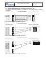
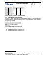
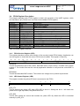
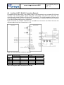
USER’S GUIDE
®
MICRO-LINE BUSMASTER BSP
RDY input
0
0
1
1
RDY_POL
0
1
0
1
RDY_STAT
0
1
1
0
Date
: 12 April 2006
Doc. no. : C641xCPU_ml_bm_ug
Iss./Rev : 1.0
Page
: 25
Meaning
not ready
ready
ready
not ready
RDY_POL
This bit controls the polarity of the RDY input. By default, it is set to 0 which means that RDY is
active high, thus a logic 1 indicates a ready condition. For externally connected hardware that has
an active-low RDY output, such as the C641xCPU host port interface, RDY_POL must be set to 1.
See also the table above for encoding of RDY_POL.
3.4.6 Auxiliary UART Enable Register (AUX_UART_EN)
The auxiliary UART enable register controls wheter athe auxiliary UART is enabled or not. This
avoids porblems with systems whre the auxiliary UART signals are used as additional ground pins,
such as previous micro-line boards.
15
1
RESERVED
r, 0
0
AUART_EN
r, w, 0
AUART_EN
Auxiliary UART enable bit. If this bit is set the auxiliary UART’s outputs are enabled. Otherwise the
signals AUX_TXD, and /AUX_RTS on micro-line® connector pins B25 and B26 are in highimpedance state. The auxiliary UART is directly routed to the micro-line® connector, without a level
converter.
The auxiliary UART must not be enabled in systems that use B25..B28 as ground pins. See also
2.3.
3.4.7 UART Registers
The C641xCPU-specific address mapping of the UART registers is in Table 4. For a detailed
description of the UART registers, please refer to [21].