1
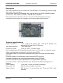
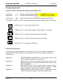
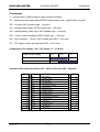
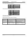
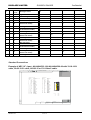
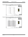
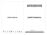
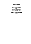
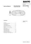
DISPLAZE LIMITED
D800DR & D640DR
Confidential
D800DR & D640DR
User Guide
D800DR_D640DR User Guide.doc
Revision: 2.9
User Manual
1 of 12
Printed: 19/07/2001
DISPLAZE LIMITED
D800DR & D640DR
Confidential
Introduction
This document provides the hardware related instructions to install a D800DR or D640DR
interface card. It explains how to supply the card, connect the card to the VGA source
signals and to the TFT LCDs, and to set up the parameters to the user's needs. The
connectors, keyboard's display are fully described. Some example of connection to LCDs
are also given.
The D800DR is suitable for driving SVGA resolution LCDs.
The D640DR is suitable for driving VGA resolution LCDs.
If you further information please contact Displaze on:Phone:
Fax:
E-mail :
Web:
+44-(0)1296-621141
+44-(0)1296-621142
[email protected]
www.displaze.com
Document Classification
This Document/message is intended only for the use of the individual or entity to which it
is addressed and contains information that is privileged and confidential. If the reader of
this message is not the intended recipient or the employee or agent responsible for
delivering the message to the recipient, you are hereby notified that any dissemination,
distribution or copying of this communication is strictly prohibited. If you have received this
communication in error, please notify sender immediately by telephone (+44 (0)1296621141) and destroy the original document/message
Disclaimer
Displaze is continually improving it's products and reserves the right to change the details
of this document without notice. Every effort has been made to ensure the accuracy of this
document, however the manufacturer cannot accept responsibility for any loss or damage
caused as a result of using this document.
Notice of any mistakes, inconsistencies or comments relating to this document would be
gratefully received by fax to Displaze. All rights reserved. No part of this document may be
reproduced, in any form or by any means, without the written permission of Displaze Ltd.
Revision History
Rev No.:
Date
Description
1
2.9
18-07-01
19-7-01
Initial Specification
Updated to new PCB layout
D800DR_D640DR User Guide.doc
Revision: 2.9
Checked
User Manual
2 of 12
Approved
Prepared
Issue Date
Printed: 19/07/2001
DISPLAZE LIMITED
D800DR & D640DR
Confidential
Description
This video card allows you to connect one LCD flat panel (TFT technology) with an analog
video output from a computer.
This interface is also fully compatible with VGA (640x400) and SVGA (800x600) modes
screens from: NEC, SANYO, SHARP, TOSHIBA and HOSIDEN…
Reduced dimensions (82 x 58 x 17 mm / 3.2 x 2.3 x 0.67 inches) and low power
consumption make easier the integration of this card inside small equipment.
Technical specifications
Graphic resolutions
: 640 x 480 pixels (VGA), 800 x 600 pixels (SVGA) and
optionally XGA mode 1024 x 768 pixels
Text mode resolution
: 720 x 400 pixels
24 bits color mode
: 8 bits per color = 16 million colors
Fully compatible with SVGA standard (vertical refresh = 60 Hz and non–interlaced mode).
Video level adjustable by software for the three colors (RGB).
Configuration with a 3 push–buttons keyboard (Clock phase, screen width and centering image,
video level).
On screen display for configuration menus (reduced OSD functions).
Permanent storage of the configuration parameters into an EEPROM.
Automatic recall of the default parameters by a simple RESET operation.
For volume orders, customer parameters may be preload as default settings prior to
shipping.
Power supplies:
5 Volts and 12 Volts (only used for backlight)
Typ. power (5v):
400 mA (with no display connected).
Optional feature:
DDC function to communicate with "Plug and Play" video
controller
D800DR_D640DR User Guide.doc
Revision: 2.9
User Manual
3 of 12
Printed: 19/07/2001
DISPLAZE LIMITED
D800DR & D640DR
Confidential
Display adjustments
Function of the 3 push–buttons keyboard and OSD menus.
Press both at power-on
to RESET factory defaults
Left button
Right button
[–]
[+]
: decrease selected parameter
: increase selected parameter
Center button
[M]
: selection between the 5 OSD menus (look at symbols after)
The RESET operation, sets the default parameters previously loaded by the manufacturer.
OSD menu N°1 = pixel clock (display width).
OSD menu N°2 = clock phase (display synchronization ; 16 steps).
OSD menu N°3 = horizontal centering image (left or right).
OSD menu N°4 = Vertical centering image (top or bottom).
OSD menu N°5 = video gain (RVB level).
Recommended method.
In order to adjust easily the image on the screen, you may use a video test chart with a
square grid to center the display, and a palette with color scale to adjust correctly the
video gain too.
Operation 1
Operation 2
Operation 3
Operation 4
D800DR_D640DR User Guide.doc
Revision: 2.9
RESET D800DR & D640DR card ; left and right buttons must
be pushed simultaneously, at the power on.
Display OSD menu N°1 by pressing the center button, then
adjust the width of the image like the width of the screen, using
left or right buttons.
Display OSD menu N°2 by a second action on center button,
then select the best clock phase which provides a stable
display, using left or right buttons (16 steps available).
Display OSD menu N°3 by a third action on center button, then
center the image horizontally, using left or right buttons.
User Manual
4 of 12
Printed: 19/07/2001
DISPLAZE LIMITED
Operation 5
D800DR & D640DR
Confidential
Display OSD menu N°4 by a fourth action on center button,
then center the image vertically, using left or right buttons.
Note : If necessary, start again the adjustments by beginning at line "Operation 2", until an entire image
perfectly centered is displayed.
Operation 6
!
Display OSD menu N°5 by a fifth action on center button, then
adjust the video gain in order to divide up the increasing color
scale on the maximum range.
These adjustments must be done both in graphic and text
modes.
Example of a video test chart.
D800DR_D640DR User Guide.doc
Revision: 2.9
User Manual
5 of 12
Printed: 19/07/2001
DISPLAZE LIMITED
D800DR & D640DR
Confidential
Connectors
J1 : configuration of display power supply (soldering bridge)
JP1 : standard analog video input (SUB D female header type – High Density 15 pins)
JP2 : not used (HE14 header type – 1x4 pins)
JP3 : general power supply (HE14 header type – 1x4 pins)
JP4 : optional analog video input (HE14 header type – 2x5 pins)
JP5 : 3 push–buttons keyboard (HE14 header type – 2x3 pins)
JP6 : color extension ; 12 bits "LSB" (header type HE10 – 2x6 pins)
JP7 : TFT display output (header type HE10 – 2x17 pins)
Configuration for display +5V / 3,3V (Strap J1 – 1x3 pins)
Display power supply
Pin 1
5V
Soldering bridge
3,3 V
Pin 2
Pin 3
Soldering bridge
Standard video input connector (JP1 - VGA 15 pins and JP4 - 2x5 pins)
JP1 –
Symbol
JP4 –
1
Rin
RED video
1
2
Gin
GREEN video
3
3
Bin
BLUE video
5
4
NC
No connection
–
5
GND
Vertical sync ground
8
6
GND
RED ground
2
7
GND
GREEN ground
4
8
GND
BLUE ground
6
9
NC
No connection
–
10
GND
Horizontal sync ground
11
NC
No connection
–
12
DDA
DDC data
–
13
Hsync
Horizontal sync
9
14
Vsync
Vertical sync
7
15
DCK
DDC clock
–
D800DR_D640DR User Guide.doc
Revision: 2.9
Signals
User Manual
6 of 12
10
Printed: 19/07/2001
DISPLAZE LIMITED
D800DR & D640DR
Confidential
Power supply connector (JP3 – 1x4 pins)
JP3 – Symbol
Function
1 +5V
General Power supply +5V
2 GND
Signal Ground
3 GND
Signal Ground
4 +12V
General Power supply +12V
3 buttons-keyboard connector (JP5 – 2x3 pins)
JP5 – Symbol
Function
1 +OSD
Increase value
2 +12V
Power supply +12V
3 –OSD
Decrease value
4 +5V
Power supply +5V
5 MOSD
OSD menu selection
6 GND
Signal Ground
JTAG connector (JP2 – 1x4 pins)
This connector is not used.
Different models of connector used on TFT displays
Connectors
Display module side connectors
Mating connectors
Header 31 pins
JAE
HIROSE
: IL310 – T31PB – VF
: DF9 – 31P – 1V
JAE
HIROSE
: IL310 – T31S – VF
: DF9 – 31S – 1V or – 1R
Header 41 pins
JAE
HIROSE
: IL310 – T41P – VF
: DF9 – 41P – 1V
JAE
HIROSE
: IL – 310 – T41S – VF
: DF9M – 41S – 1V
Header 34 pins
Composed by 3 JAE connectors :
CN1 (10pins) = IL – Z – 10PL – SMTY
CN2 (13pins) = IL – Z – 13PL – SMTY
CN3 (11pins) = IL – Z – 11PL – SMTY
D800DR_D640DR User Guide.doc
Revision: 2.9
User Manual
7 of 12
Composed by 3 JAE connectors :
To plug into CN1 : IL – Z – 10S – S125C3
To plug into CN2 : IL – Z – 13S – S125C3
To plug into CN3 : IL – Z – 11S – S125C3
Printed: 19/07/2001
DISPLAZE LIMITED
D800DR & D640DR
Confidential
Mechanical dimensions of the D800DR & D640DR card
Total Height = 17 mm
82 mm
4,5 8
25,4
JP1
1
4,5
U3
7,5
15
4,5
4,5
7,5
JP3
9
1
JP4
1
1
7
11
JP2
JP5
U5
49
58 mm
1
U1
11
JP6
6
4,5
1
JP7
7
2
1
3
20,5
1
5
9,5
58,5
73
D800DR_D640DR User Guide.doc
Revision: 2.9
J1
4 metallic fixing holes Diam. = 3,2 mm
User Manual
8 of 12
Printed: 19/07/2001
DISPLAZE LIMITED
D800DR & D640DR
Confidential
D800DR & D640DR
connectors
Connection between the D800DR & D640DRcard and some NEC TFT
displays
JP7
Symbol
Function
JP6
NL6448AC20–06
NL6448AC33–17
NL6448AC30–10 NL6448AC33–18
NL6448AC33–10 NL6448AC33–24
NL6448AC33–27 NL6448BC63-01
NL8060AC26–02 NL6448AC33–29
NL6448BC20–08
NL6448BC33–31
NL6448CC33–30
NL6448AC33–13
NL8060AC26–04
NL8060AC26–11
NL8060AC31–01
NL8060AC31–12
NL8060BC31–02
NL8060BC31–17
Header 34 pins
Header 31 pins
Header 40 pins
Header 41 pins
1
TFTCLK Pixel Clock
1
2
2
2
2
GND
Signal Ground
2
1
1
1
3
GND
Signal Ground
3
1
1
3
4
Hsync
Horizontal synchro
4
3
3
4
5
Vsync
Vertical synchro
5
4
4
5
6
GND
Signal Ground
6
5
5
6 + 7 + 8 + 12
7
R4
RED signal bit 4
7
8
10
11
8
R5
RED signal bit 5
8
9
11
13
9
R6
RED signal bit 6
9
10
12
14
10
R7
RED signal bit 7 (MSB)
10
11
13
15
11
GND
Signal Ground
11
12
14
16 + 17 + 18 + 22
12
G4
GREEN signal bit 4
12
15
19
21
13
G5
GREEN signal bit 5
13
16
20
23
14
G6
GREEN signal bit 6
14
17
21
24
15
G7
GREEN signal bit 7 (MSB)
15
18
22
25
16
GND
Signal Ground
16
19
23
26 + 27 + 28 + 32
17
B4
Signal BLEU bit 4
17
22
28
31
18
B5
Signal BLEU bit 5
18
23
29
33
19
B6
Signal BLEU bit 6
19
24
30
34
20
B7
Signal BLEU bit 7 (MSB)
20
25
31
35
21
GND
Signal Ground
21
26
32
36 + 38
22
GND
Signal Ground
22
23
Display
On/Off
Backlight control
23
24
GND
Signal Ground
24
26
25
+Vcc
Display supply +5V/3,3V
25
28
34
39
26
+Vbl
Backlight supply +12V
26
–
27
+Vbl
Backlight supply +12V
27
–
28
NC
No connection
28
–
29
GNDB
Backlight Ground
29
26
30
GNDB
Backlight Ground
30
26
36
31
DE
DATA ENABLE (DE)
31
27
33
37
32
+Vcc
Display supply +5V/3,3V
32
29
35
40
D800DR_D640DR User Guide.doc
Revision: 2.9
User Manual
9 of 12
Printed: 19/07/2001
DISPLAZE LIMITED
D800DR & D640DR
33
Display
On/Off
Backlight control
33
34
GND
Signal Ground
34
26
Confidential
–
–
MVA
Best viewing select
–
–
36
–
–
–
R/L
Scan direction (horizontal)
–
–
37
–
–
–
U/D
Scan direction (vertical)
–
–
38
–
1
R2
RED signal bit 2 (LSB for
18 bits color mode)
–
6
8
9
2
R3
RED signal bit 3
–
7
9
10
3
G2
GREEN signal bit 2 (LSB
for 18 bits color mode)
–
13
17
19
4
G3
GREEN signal bit 3
–
14
18
20
5
B2
BLUE signal bit 2 (LSB for
18 bits color mode)
–
20
26
29
6
B3
BLUE signal bit 3
–
21
27
30
7
R0
RED signal bit 0 (LSB for
24 bits color mode)
6
8
R1
RED signal bit 1
7
9
G0
GREEN signal bit 0 (LSB
for 24 bits color mode)
15
10
G1
GREEN signal bit 1
16
11
B0
BLUE signal bit 0 (LSB for
24 bits color mode)
24
12
B1
BLUE signal bit 1
25
Standard Connections
Example of NEC 10" 4 part.: NL6448AC33-18 & NL6448AC20-06 with 33-18-10-31
cable, 20-06-10-31 cable, AS100-15 or C31-104xxC cable.
1
2
3
DRAWN TO
BS 308
5
4
3RD.ANGLE PROJECTION
6
7
8
9
10
11
12
PARTICULARS OF HOLES
UNLESS OTHERWISE STATED:- (1) REMOVE ALL BURRS AND SHARP EDGES.
(2) A RADIUS OR CHAMFER OF O.2(MAX) IS PERMITTED IN THE
CORNERS OF BLIND HOLES, RECESSES OR STEPS
REF. QTY
SIZE
3.3 DIA. HOLES CSK. FOR M3 SCREW HEAD ON OUTSIDE FACES
USED ON
M5 NUTSERTS (STANDARD HANKS)
A
3.3 DIA. HOLES
16.5 DIA. HOLE
M3x15 PRESS STUDS (ON INSIDE FACE)
4.2 DIA. HOLES
5.0 DIA. HOLES
B
Function
Ground
Dot clock
Horizontal sync.
Vertical sync.
Ground
Red data (LSB)
Red data
Red data
Red data
Red data
Red data (MSB)
Ground
Green data (LSB)
Green data
Green data
Green data
Green data
Green data (MSB)
Ground
Blue data (LSB)
Blue data
Blue data
Blue data
Blue data
Blue data (MSB)
Ground
Data enable
Power supply
Power supply
Non-connection
Symbol
GND
CLK
Hsync
Vsync
GND
R0
R1
R2
R3
R4
R5
GND
G0
G1
G2
G3
G4
G5
GND
B0
B1
B2
B3
B4
B5
GND
DE
VCC
C
1
2
9
10
JP3
HE14 type
42pin IDC socket
Pin No.
10
9
12
13
14
6
5
15
16
17
18
19
4
3
20
21
22
23
24
2
1
25
26
27
28
29
39
33
Symbol
GND
CLK
Hsync
Vsync
GND
R0
R1
R2
R3
R4
R5
GND
G0
G1
G2
G3
G4
G5
GND
B0
B1
B2
B3
B4
B5
GND
DE
VCC
VCC
N. C.
JP6
D640DR Connector
Manufacturer::
Type:
Pin No.
1
2
3
4
5
6
7
8
9
10
11
12
13
14
15
16
17
18
19
20
21
22
23
24
25
26
27
28
29
30
D
JP7
NL6448AC33-18/24 Connector
Manufacturer::
HIROSE ELECTRIC CO., LTD.
Type:
DF9-31S-1V
E
Top view of PCB Header
F
Xx =
=
=
15
20
33
l = 15cm
l = 20cm
l = 33cm
G
H
ENG. APP.
CHANGE
CHECKED
MATERIAL
DRAWN
M.I.C.
D800DR_D640DR User Guide.doc
Revision: 2.9
PROTECTIVE FINISH
SCALE: 1:2
GENERAL TOLERANCES (UNLESS
OTHERWISE SPECIFIED)
2 DEC. PLACES +/- 0.1mm
1 DEC. PLACE +/- 0.4mm
ANGULAR +/- 1/2 °
User Manual
10 of 12
DISPLAZE LTD.
Cherry Tree House, Aston Hill, Halton, England HP22 5NQ
TITLE
C31-104-xx - D640DR to 10.4“ VGA LCD cable
MOD.NO.
1 19-5-99
ISS
DATE
(UNLESS OTHERWISE
STATED)
CONTRACTOR'S DRAWING REF.
DIMENSIONS IN m.m.
C31-104-xx.cdr
Printed: 19/07/2001
DISPLAZE LIMITED
D800DR & D640DR
Confidential
Example of NEC 12.1” part.: NL8060AC31-12 cable for the D800DR rev1
1
2
3
DRAWN TO
BS 308
5
4
3RD.ANGLE PROJECTION
6
7
8
9
10
11
12
PARTICULARS OF HOLES
UNLESS OTHERWISE STATED:- (1) REMOVE ALL BURRS AND SHARP EDGES.
(2) A RADIUS OR CHAMFER OF O.2(MAX) IS PERMITTED IN THE
CORNERS OF BLIND HOLES, RECESSES OR STEPS
REF. QTY
SIZE
3.3 DIA. HOLES CSK. FOR M3 SCREW HEAD ON OUTSIDE FACES
USED ON
M5 NUTSERTS (STANDARD HANKS)
A
3.3 DIA. HOLES
16.5 DIA. HOLE
M3x15 PRESS STUDS (ON INSIDE FACE)
4.2 DIA. HOLES
5.0 DIA. HOLES
B
Pin No.
Symbol
10
GND
9
CLK
11
GND
12
Hsync
13
Vsync
14
GND
14
GND
14
GND
6
R0
5
R1
15
R2
14
GND
16
R3
17
R4
18
R5
19
GND
19
GND
19
GND
4
G0
3
G1
20
G2
24
GND
21
G3
22
G4
23
G5
24
GND
24
GND
29
GND
2
B0
1
B1
25
B2
30
GND
26
B3
27
B4
28
B5
38
GND
39
DE
No Connect
33
VCC
40
VCC
42
GND
Function
Ground
Dot clock
Ground
Horizontal sync.
Vertical sync.
Ground
Ground
Ground
Red data (LSB)
Red data
Red data
Ground
Red data
Red data
Red data (MSB)
Ground
Ground
Ground
Green data (LSB)
Green data
Green data
Ground
Green data
Green data
Green data (MSB)
Ground
Ground
Ground
Blue data (LSB)
Blue data
Blue data
Ground
Blue data
Blue data
Blue data (MSB)
Ground
Data enable
35
37
Backlight +ve
Backlight -ve
Symbol
GND
CLK
GND
Hsync
Vsync
GND
GND
GND
R0
R1
R2
GND
R3
R4
R5
GND
GND
GND
G0
G1
G2
GND
G3
G4
G5
GND
GND
GND
B0
B1
B2
GND
B3
B4
B5
GND
DE
MVA
VCC
VCC
DSP
Function
Ground
Dot clock
Ground
Horizontal sync.
Vertical sync.
Ground
Ground
Ground
Red data (LSB)
Red data
Red data
Ground
Red data
Red data
Red data (MSB)
Ground
Ground
Ground
Green data (LSB)
Green data
Green data
Ground
Green data
Green data
Green data (MSB)
Ground
Ground
Ground
Blue data (LSB)
Blue data
Blue data
Ground
Blue data
Blue data
Blue data (MSB)
Ground
Data enable
Viewing Angle Select
(5V/3.3) Power supply
(5V/3.3) Power Supply
Scan Direction
+12V
GND
C
1
2
9
10
JP3
Pin No.
1
2
3
4
5
6
7
8
9
10
11
12
13
14
15
16
17
18
19
20
21
22
23
24
25
26
27
28
29
30
31
32
33
34
35
36
37
38
39
40
41
JP6
D800DRv1 Connector
Manufacturer::
HE14 type
Type:
42pin IDC socket
D
JP7
NL8060AC31-12G, NL8060BC31-17 Connector
Manufacturer::
HIROSE ELECTRIC CO., LTD.
Type:
DF9-41S-1V
E
Top view of PCB Header
F
Xx =
=
20
33
l = 20cm
l = 33cm
G
Power supply
Power supply
L = Normal, H = Reverse
Yellow tail
Black tail
H
ENG. APP.
Added MVA/DSP info
CHANGE
CHECKED
MATERIAL
PROTECTIVE FINISH
DISPLAZE LTD.
SCALE: 1:2
M.I.C.
2
21-06-00
1
19-5-00
ISS
DATE
DIMENSIONS IN m.m.
(UNLESS OTHERWISE
STATED)
CONTRACTOR'S DRAWING REF.
Cherry Tree House, Aston Hill, Halton, England HP22 5NQ
TITLE
GENERAL TOLERANCES (UNLESS
OTHERWISE SPECIFIED)
2 DEC. PLACES +/- 0.1mm
1 DEC. PLACE +/- 0.4mm
ANGULAR +/- 1/2 °
DRAWN
A
MOD.NO.
C41-121-xxC - D800DR to 12.1“ SVGA LCD cable
C41-121-xxC.cdr
Example of NEC 12.1” part.: NL8060AC26-11 cable for the D800DR rev1
1
2
3
DRAWN TO
BS 308
5
4
3RD.ANGLE PROJECTION
6
7
8
9
10
11
12
PARTICULARS OF HOLES
UNLESS OTHERWISE STATED:- (1) REMOVE ALL BURRS AND SHARP EDGES.
(2) A RADIUS OR CHAMFER OF O.2(MAX) IS PERMITTED IN THE
CORNERS OF BLIND HOLES, RECESSES OR STEPS
REF. QTY
SIZE
3.3 DIA. HOLES CSK. FOR M3 SCREW HEAD ON OUTSIDE FACES
USED ON
M5 NUTSERTS (STANDARD HANKS)
A
3.3 DIA. HOLES
16.5 DIA. HOLE
M3x15 PRESS STUDS (ON INSIDE FACE)
4.2 DIA. HOLES
5.0 DIA. HOLES
B
Pin No.
10
9
11
12
13
14
14
14
6
5
15
14
16
17
18
19
19
19
4
3
20
24
21
22
23
24
24
29
2
1
25
30
26
27
28
38
39
33
33
40
42
Symbol
GND
CLK
GND
Hsync
Vsync
GND
GND
GND
R0
R1
R2
GND
R3
R4
R5
GND
GND
GND
G0
G1
G2
GND
G3
G4
G5
GND
GND
GND
B0
B1
B2
GND
B3
B4
B5
GND
DE
VCC
VCC
VCC
GND
Function
Ground
Dot clock
Ground
Horizontal sync.
Vertical sync.
Ground
Ground
Ground
Red data (LSB)
Red data
Red data
Ground
Red data
Red data
Red data (MSB)
Ground
Ground
Ground
Green data (LSB)
Green data
Green data
Ground
Green data
Green data
Green data (MSB)
Ground
Ground
Ground
Blue data (LSB)
Blue data
Blue data
Ground
Blue data
Blue data
Blue data (MSB)
Ground
Data enable
Power Supply, DPS/26-17 L= Rev. H=Normal
Power supply
Power supply
L = DE Mode, H = Fixed
35
37
+12V
GND
Backlight +ve
Backlight -ve
Symbol
GND
CLK
GND
Hsync
Vsync
GND
GND
GND
R0
R1
R2
GND
R3
R4
R5
GND
GND
GND
G0
G1
G2
GND
G3
G4
G5
GND
GND
GND
B0
B1
B2
GND
B3
B4
B5
GND
DE
VCC/DPS
VCC
VCC
MODE
Function
Ground
Dot clock
Ground
Horizontal sync.
Vertical sync.
Ground
Ground
Ground
Red data (LSB)
Red data
Red data
Ground
Red data
Red data
Red data (MSB)
Ground
Ground
Ground
Green data (LSB)
Green data
Green data
Ground
Green data
Green data
Green data (MSB)
Ground
Ground
Ground
Blue data (LSB)
Blue data
Blue data
Ground
Blue data
Blue data
Blue data (MSB)
Ground
Data enable
(5V/3.3) Power supply, Scan Direction Select
(5V/3.3) Power supply
(5V/3.3) Power Supply
Timing Mode Select
C
1
2
9
10
JP3
Pin No.
1
2
3
4
5
6
7
8
9
10
11
12
13
14
15
16
17
18
19
20
21
22
23
24
25
26
27
28
29
30
31
32
33
34
35
36
37
38
39
40
41
JP6
D800DRv1 Connector
Manufacturer::
HE14 type
Type:
42pin IDC socket
D
JP7
NL8060AC26-11/17 Connector
Manufacturer::
HIROSE ELECTRIC CO., LTD.
Type:
DF9-41S-1V
E
Top view of PCB Header
F
Xx =
=
20
33
l = 20cm
l = 33cm
G
Yellow tail
Black tail
H
DPS info for 26-17 added
ENG. APP.
Added Mode info & 33Vcc
CHANGE
CHECKED
MATERIAL
DRAWN
M.I.C.
D800DR_D640DR User Guide.doc
Revision: 2.9
PROTECTIVE FINISH
SCALE: 1:2
GENERAL TOLERANCES (UNLESS
OTHERWISE SPECIFIED)
2 DEC. PLACES +/- 0.1mm
1 DEC. PLACE +/- 0.4mm
ANGULAR +/- 1/2 °
User Manual
11 of 12
DISPLAZE LTD.
Cherry Tree House, Aston Hill, Halton, England HP22 5NQ
TITLE
C41-104-xx - D800DR to 10.4“ SVGA LCD cable
3
6-7-00
A
2
21-6-00
MOD.NO.
B
1
19-5-00
ISS
DATE
DIMENSIONS IN m.m.
(UNLESS OTHERWISE
STATED)
CONTRACTOR'S DRAWING REF.
C41-104-xx.cdr
Printed: 19/07/2001
DISPLAZE LIMITED
D800DR & D640DR
Confidential
Parts List
D800DR & D640DR
Part
Notes
D800DR
SVGA LCD Interface PCB
D640DR
VGA LCD Interface PCB
D800DR-OSD
OSD Keyboard included with evaluation units only.1
D800DR-PSL
Internal Power Lead
Notes: 1
1off D800DR-OSD is supplied for every 5off D800DR.
Optional Extras
Part
Notes
D800DR-OSD
OSD Keyboard included with evaluation units only.1
D800DR-PSL
Internal Power Lead
AX0041
LCD Interface cable for NL6448AC33-10
C31-104-20
LCD Interface cable for NL6448AC33-18, 20-06
C41-104-20
LCD Interface cable for NL8060BC26-17
C41-121-20
LCD Interface cable for NL8060BC31-17
VGA-PSL
Combined VGA and Power lead for Chassis.
Warranty
12 months from date of shipment
Shipping
Shipping by TNT, Federal Express or Airborne Express may be arranged upon request
Packaging
Standard Export Carton
D800DR_D640DR User Guide.doc
Revision: 2.9
User Manual
12 of 12
Printed: 19/07/2001