1
SATELLINE-1915
User Guide version 1.0
IMPORTANT NOTICE
Parts of this manual are used by permission of MaxStream, Inc. All rights to this manual are
owned solely by SATEL Oy (referred to in this user guide as SATEL). All rights reserved. The
copying of this manual (without the written permission from the owner) by printing, copying,
recording or by any other means, or the full or partial translation of the manual to any other
language, including all programming languages, using any electrical, mechanical, magnetic,
optical, manual or other methods or devices is forbidden.
SATEL reserves the right to change the technical specifications or functions of its products, or to
discontinue the manufacture of any of its products or to discontinue the support of any of its
products, without any written announcement and urges its customers to ensure, that the
information at their disposal is valid.
SATEL software and programs are delivered ”as is”. The manufacturer does not grant any kind
of warranty including guarantees on suitability and applicability to a certain application. Under
no circumstances is the manufacturer or the developer of a program responsible for any
possible damages caused by the use of a program. The names of the programs as well as all
copyrights relating to the programs are the sole property of SATEL. Any transfer, licensing to a
third party, leasing, renting, transportation, copying, editing, translating, modifying into another
programming language or reverse engineering for any intent is forbidden without the written
consent of SATEL.
SATEL PRODUCTS HAVE NOT BEEN DESIGNED, INTENDED NOR INSPECTED
TO BE USED IN ANY LIFE SUPPORT RELATED DEVICE OR SYSTEM RELATED
FUNCTION NOR AS A PART OF ANY OTHER CRITICAL SYSTEM AND ARE
GRANTED NO FUNCTIONAL WARRANTY IF THEY ARE USED IN ANY OF THE
APPLICATIONS MENTIONED.
Salo, FINLAND 2008
1
SATELLINE-1915
User Guide version 1.0
RESTRICTIONS ON USE
WARNING: This equipment has been is approved only for mobile and base station transmitting
devices. Antenna(s) used for this transmitter must be installed to provide a separation distance of
at least 30 cm from all persons and must not be co-located or operating in conjunction with any
other antenna or transmitter.
Contains FCC ID: OUR-9XTEND. The enclosed device complies with the part 15 of the FCC
rules. Operation is subject to the following two conditions: (i.) this device may not cause harmful
interference and (ii.) this device must accept any interference received, including interference
that may cause undesired operation.
2
SATELLINE-1915
User Guide version 1.0
PRODUCT CONFORMITY
Hereby, SATEL Oy declares that SATELLINE-1915 radio modem is in compliance with the
essential requirements of FCC Part 15 (USA), IC (Industry Canada) and C-TICK (Australia)
regulations.
3
SATELLINE-1915
User Guide version 1.0
WARRANTY AND SAFETY INSTRUCTIONS
Read these safety instructions carefully before using the product:
o Warranty will be void, if the product is used in any way, which is in contradiction with the
instructions given in this manual, or if the housing of the radio modem has been opened
or tampered with.
o The radio modem is to be used only on frequencies allocated by local authorities and
without exceeding the given maximum allowed output power ratings. SATEL is not
responsible, if any products manufactured by it are used in unlawful ways.
o The devices mentioned in this manual are to be used only according to the instructions
described in this manual. Faultless and safe operation of the devices can be guaranteed
only if the transport, storage, operation and handling of the devices is appropriate. This
also applies to the maintenance of the products.
o To prevent damage to both the radio modem and any terminal devices must always be
switched OFF before connecting or disconnecting the serial connection cable. It should
be ascertained that different devices used have the same ground potential. Before
connecting any power cables the output voltage of the power supply should be checked.
4
SATELLINE-1915
User Guide version 1.0
TABLE OF CONTENTS
IMPORTANT NOTICE............................................................................................. 1
RESTRICTIONS ON USE......................................................................................... 2
PRODUCT CONFORMITY ....................................................................................... 3
WARRANTY AND SAFETY INSTRUCTIONS ............................................................. 4
TABLE OF CONTENTS............................................................................................ 5
INTRODUCTION.................................................................................................... 7
1 SATELLINE-1915 RADIO DATA MODEM .......................................................... 8
1.1 SATELLINE-1915 Technical specifications.................................................... 8
2 CONNECTIONS................................................................................................ 9
2.1 Power Supply............................................................................................... 9
2.2 DIN 41651-16 pin connector functions ..................................................... 10
2.2.1 Pin configuration .................................................................................................. 10
3 LEDS .............................................................................................................. 13
3.1 LED-indicators ........................................................................................... 13
4 SERIAL INTERFACE......................................................................................... 14
4.1 RS-232 14
4.2 Serial interface data format...................................................................... 14
4.3 Serial interface handshake....................................................................... 16
4.3.1 Software handshaking (XON/XOFF) ....................................................................... 16
4.3.2 Hardware handshaking (RTS/CTS) ......................................................................... 16
4.4 Serial interface packetization ................................................................... 17
5 RF INTERFACE................................................................................................ 18
5
SATELLINE-1915
User Guide version 1.0
5.1 Transmitter ................................................................................................ 18
5.2 Receiver ..................................................................................................... 19
5.3 Error checking ........................................................................................... 20
5.4 Radio data rate and packet length........................................................... 20
6 COMMAND MODE ......................................................................................... 21
6.1 Configuration............................................................................................. 21
6.1.1 Changing the settings with AT commands ............................................................... 21
6.1.2 Back-up method for entering the Command Mode .................................................. 23
6.1.3 Changing the settings with Binary Commands ......................................................... 23
6.1.4 Restoring default settings ....................................................................................... 24
7 RADIO MODES .............................................................................................. 25
7.1 Radio packet ............................................................................................. 26
7.2 Addressing ................................................................................................ 27
7.2.1 API mode............................................................................................................. 27
7.3 Multiple Transmit ...................................................................................... 28
7.4 Acknowledgements ................................................................................... 28
7.5 Short range point-to-point example......................................................... 29
7.6 Short range point-to-multipoint example................................................. 30
7.7 Short range sensor example ..................................................................... 30
7.8 Repeater .................................................................................................... 31
7.9 Long range point-to-point example with repeater .................................. 32
7.10 Long range point-to-multipoint example with repeater ........................ 33
8 SLEEP MODES ................................................................................................ 34
9 DIAGNOSTICS AND TESTING ........................................................................ 36
10 APPENDIX A................................................................................................ 40
6
SATELLINE-1915
User Guide version 1.0
INTRODUCTION
SATEL Oy is a Finnish electronics and telecommunications company specialised in the design
and manufacturing of wireless data communication products. SATEL designs, manufactures and
sells radio modems intended for use in applications ranging from data transfer to alarm relaying
systems. End users of SATEL products include industrial companies, public organisations and
private persons.
SATEL is one of the leading radio modem suppliers worldwide. The SATEL radio modems are
type approved in most countries globally.
Primary characteristics of SATELLINE – 1915 are listed below:
o SATELLINE-1915 radio has a raw data rate of 9.6 kbps or 115.2 kbps
o SATELLINE-1915 radio modems DTE-interface (Data Terminal Equipment, user device) is
electrically compatible with the RS-232 serial interface. RD, TD, RTS, CTS, DTR, DSR
lines are implemented.
o Settings can be changed with AT commands or binary commands.
o SATELLINE-1915 radio modem software can be updated using a PC and special
programming software.
User guide version information
This version of the User Guide is applicable for SATELLINE-1915 having the firmware version
2040 or later.
7
SATELLINE-1915
User Guide version 1.0
1 SATELLINE-1915 RADIO DATA MODEM
1.1 SATELLINE-1915 Technical specifications
RADIO TRANSCEIVER
Frequency Range
Communication Mode
Hopping Patterns
Channels in Hopping Pattern
Radio Speed
RADIO TRANSMITTER
Carrier Power
RADIO RECEIVER
Sensitivity
MODEM
Interface
Interface Connector
Data Speed of Serial Interface
Data format
GENERAL
Operating Voltage
Power Consumption (average)
Temperature Range
- Operating
- Storage
Antenna Connector
Housing
Size H x W x D
Installation Plate
Weight
902 …. 928 MHz
Half Duplex Frequency Hopping
10 different
50
9600 / 115200 bps
1, 10, 100, 500, 1000 mW / 50 ohm
-110 dBm @ 9600bps (BER < 10E-4)
-100 dBm @ 115200bps (BER < 10E-4)
RS-232
DIN41651-16pin (male)
10 – 230400 bps (also non-standard baud rates
between 10 … 230400)
Asynchronous RS-232
+ 8... + 30 Vdc
< 0.72 VA (60 mA @ 12 V) Receive
< 1.1 VA (90 mA @ 12 V / 10 mW) Transmit
< 5.0 VA (420 mA @12 V / 1 W) Transmit
< 0.024 VA (2 mA@12 V) Sleep mode
-25 °C ... +55 °C (tests acc. To ETSI standards)
-40 °C ... +75 °C (absolutely min. / max.)
-40 °C ... +85 °C
Reverse Polarity SMA, 50 ohm, male
Plastic / Aluminium enclosure
125 x 57 x 19 mm
130 x 63 x 1 mm
115 g
NOTE! Values are subject to change without notice.
8
SATELLINE-1915
User Guide version 1.0
2 CONNECTIONS
2.1 Power Supply
The allowed operating voltage is +8 - +30 Vdc. The pin 1 of the DIN41651-16 connector is
connected to the positive power supply line. Negative power supply line (ground) is connected to
pin 2 of the DIN41651-16 connector. The DTR-line of the radio modem which is connected to
pin 14 can be used as an ON / STANDBY –switch.
Connecting the DTR to ground will turn the radio modem OFF. Leaving the DTR unconnected
will turn ON the radio modem (the radio modem has internal pull-up for DTR).
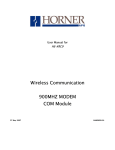
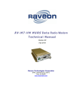
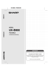
The basic connection between a radio modem and the serial port (RS-232) of a PC is described
in the schematic below.
9-PIN D -CONN.
3
2
5
25-PIN D -CONN.
TD
2
RD
3
SGND
7
RADIOMODEM
TD
TD
RD
RD
SGND
SGND
+Vb
+Vb
GND
GND
NOTE! The modem has an internal multifuse; external fuse is not required.
9
SATELLINE-1915
User Guide version 1.0
2.2 DIN 41651-16 pin connector functions
The radio modem is referred to as DCE (Data Communication Equipment) whereas the PC is
referred to as DTE (Data Terminal Equipment). SATELLINE-1915 radio modem includes a 16pin DIN41651-type male connector, which contains all the connections required to establish
communication between the radio modem, acting as the DCE, and the PC, acting as the DTE.
All EMC-requirements set forth by authorities have been taken into account in the design of the
radio modem. The user of the radio modem is thereby not required to take any special actions
regarding EMC-shielding of the radio modem.
NOTE!
When the PROG-pin (pin 7 of the DIN41651-16 pin -connector) is connected to ground,
the radio modem is in the Programming Mode.
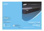
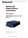
2.2.1 Pin configuration
The pin configuration of the SATELLINE – 1915 is defined in the following table.
The picture below indicates the order of the pins.
PIN 15
PIN 1
PIN 16
PIN 2
DIN41651-16 pin male connector of the radio modem
(the modem DTE-connector facing the viewer).
10
SATELLINE-1915
User Guide version 1.0
Direction I N is data from DTE (Data Terminal Equipment) to the radio modem.
Direction O UT is data from the radio modem to the DTE.
PORT
PIN TO
PORT RS-232 9
OUT
10 OUT
11 IN
12 IN
13 OUT
14 IN
NAME
DSR
RD
RTS/CMD
TD
CTS
DTR
COMMON
PINS
1
DC
Vb
2
3
4
5
6
7
GND
IN
IN
GND
AUX IO1
AUX IO2
AUX IO3
\SHDN
\PROG
8
15
16
NC
NC
SGND SGND
EXPLANATION
Data set ready (internally connected to DTR)
Receive data
Ready to send / Binary Command Mode
Transmit data
Clear to send
Data terminal ready (modem ON / OFF, internal
pull-up)
DC supply voltage
DC ground
do not connect
do not connect
do not connect
modem power down, active low (internal pull-up)
AT Command Mode back-up method (internal
pull-up)
not connected
not connected
Signal ground
Description of pins:
RD = R eceive D ata. Output of the data received. Data from the radio modem to the DTE.
TD = T ransmit D ata. Input of the data to be transmitted. Data from the DTE to the radio
modem.
CTS = C lear T o S end in hardware handshake.
RTS/CMD = R equest T o S end or Binary Command Mode. The function of this line can be
changed between hardware handshake (RTS), Binary Command Mode, or no handshake
(default) EI TOIMI
DTR = D ata T erminal R eady. Terminal in operation. When the DTR-line is left unconnected the
radio modem is ON. If the DTR pins are connected to GND or SGND the radio modem will turn
OFF.
DSR = D ata S et R eady. Indicates that the radio modem is switched ON (internally connected to
the DTR).
11
SATELLINE-1915
User Guide version 1.0
PROG = Back-up method for entering AT Command Mode. Ground this line at start-up to get
to the Command Mode at 9600 bps regardless of the baud rate settings.
GND = negative pole of the operating voltage and the signal ground.
SGND = signal ground, internally connected to GND
+Vb = positive pole of the operating voltage.
NOTE!
GND and SGND are internally connected together.
12
SATELLINE-1915
User Guide version 1.0
3 LEDS
3.1 LED-indicators
There are five LED-indicators on the front panel of the radio modem and they give an indication
of the status of the radio interface, serial port and power supply.
LED Indication
TX
Radio transmission
/ Pin Sleep
OFF
No signal
TD
RX
RD
PWR
No data
No data
Inactive
No power or DTR
line is grounded
TD-line status
Radio reception
RD-line status
Power
Red
Transmission /
Constant red in Pin
Sleep mode
Data
Green
Reception
Data
Radio modem
ON
Description of the LED-indicators:
TX indicates that the radio modem is sending data via the antenna connector. If the Pin Sleep
mode is enabled in the settings and the SHDN-line is grounded the radio modem will be in Pin
Sleep mode and the TX is constant red.
TD indicates that the radio modem is receiving data via the serial port, TD-line, pin 12.
RX indicates that the radio modem is receiving data via the antenna connector.
RD indicates that the radio modem is sending data via the serial port, RD-line, pin 10.
PWR indicates the power is connected. If the DTR-line is grounded the radio modem is OFF.
13
SATELLINE-1915
User Guide version 1.0
4 SERIAL INTERFACE
4.1 RS-232
RS-232 standard defines the method of serial data transfer between a computer and its
peripherals. The definition includes both the interface type and signal levels. Most computers
and peripherals contain one or more RS-232 type serial ports. The RS-232 standard uses
transmission lines, in which each single signal line level is referenced to a common ground level.
RS-232 has been designed to be use in serial transfer of data in cases where the distance
between communicating equipment is less than 15 m. The otherwise useful RS-232 standard is
applied in a multitude of slightly differing ways (e.g. different pin configurations) and for this
reason different computers and peripherals are not necessarily directly compatible with each
other.
NOTE!
When connecting equipment-using RS-232 make sure that the equipment are to be
connected together or share the same ground potential (or that the signal ground of one
and/or both of the devices are floating). Major differences in ground potentials will lead to
large currents flowing in the SGND wire of the RS-232 interface which might lead to
malfunctions or damage to the connected devices!
Supported standard serial speeds are 1200, 2400, 4800, 9600, 19200, 38400, 57600,
115200 and 230400 bps. Also non-standard baud rates are supported between 10 … 230400
bps.
Hardware handshake can be used but it has to be set ON in command mode.
4.2 Serial interface data format
The SATELLINE-1915 radio modem serial interfaces use asynchronous data format. No external
synchronising signal is needed, since necessary timing information is acquired from the start and
stop bits transmitted before and after each data byte.
The data transfer speed of the serial interfaces can be set to 1200, 2400, 4800, 9600, 19200,
38400, 57600, 115200 and 230400 bps (b
b its p er s econd). The length of the data field must
be 8 bits. A parity bit may also be used. The number of stop bits can be selected (1 or 2 bits).
One character to be transmitted will thus contain a start bit, the data bits (which define the
actual character in question), an optional parity bit and one or two stop bits. The overall length
of one character is therefore 10, 11 or 12 bits. This should be taken into account when
calculating the data throughput capability of a system. In other words, also the number of start,
stop and parity bits must be considered. A useful rule of thumb is that at a data transfer speed of
9600 bps, the transmission of one character will require roughly one millisecond (1 ms).
14
SATELLINE-1915
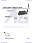
User Guide version 1.0
Start
Data
Parity
Stop
Asynchronous character data format.
Example: With an 8-bit data character length and taking for example a decimal value of
”204”, which corresponds to a binary value of ”11001100” and with a start bit value of ”0”,
parity bit set to either “NO” (NONE), ”0” or ”1” and with a stop bit value of ”1”, the possible
combinations are listed in the table below:
DATA FORMAT
8 bit, no parity, 1 stop bit
8 bit, even parity, 1 stop bit
8 bit, odd parity, 1 stop bit
8 bit, mark parity, 1 stop bit
8 bit, space parity, 1 stop bit
8 bit, no parity, 2 stop bits
8 bit, even parity, 2 stop bits
8 bit, odd parity, 2 stop bits
8 bit, mark parity, 2 stop bits
8 bit, space parity, 2 stop bits
CHARACTER
0110011001
01100110001
01100110011
01100110011
01100110001
01100110011
011001100011
011001100111
011001100111
011001100011
CHARACTER LENGTH
10 bit
11 bit
11 bit
11 bit
11 bit
11 bit
12 bit
12 bit
12 bit
12 bit
If the settings of data speed, character length, parity or the number of stop bits differ between
the radio modem and the terminal, errors will be introduced into the transferred data. The serial
port settings of each individual radio modem in a system can be different. In other words, the
data transfer speed; parity and number of stop bits can be different in different parts of a same
system.
AT / BIN
Description
ATBD / 0x15 Query / Set serial data speed
0 = 1200
1 = 2400
2 = 4800
3 = 9600
4 = 19200
5 = 38400
6 = 57600
7 = 115200
8 = 230400
ATNB / 0x23 Query / Set serial data parity
0 = no parity (or 7 bit with any parity)
1 = even
2 = odd
3 = mark
4 = space
ATSB / 0x37 Query/Set serial data stop bits
0 = 1 stop bit
1= 2 stop bits
15
Input
0-0x8
Default
0x3
Response
1 byte
0 – 0x4
0x0
1 byte
0-0x1
0x0
1 byte
SATELLINE-1915
User Guide version 1.0
4.3 Serial interface handshake
When using the RS-232 serial interface, handshake signals can be used to control the data
transfer. Handshaking is used by the terminal to request a permission to send data to the radio
modem. Handshaking is used by the radio modem to inform the terminal that the radio modem
serial data input buffer is has space or is full. By default handshaking is used to stop data flow
when there is space for only 17 bytes in input buffer. The input buffer size is 2048 bytes.
SATELLINE-1915 supports software and hardware handshaking.
4.3.1 Software handshaking (XON/XOFF)
In software handshaking (XON/XOFF) the radio modem will transmit XOFF character (0x13) to
the terminal when the input buffer is full. When the input buffer has space the radio modem will
transmit XON character (0x11) to the terminal to continue transmission.
4.3.2 Hardware handshaking (RTS/CTS)
In hardware handshaking (RTS/CTS) separate signal lines are used to control the data flow.
Line
RTS (Request To Send)
CTS (Clear To Send)
Direction
To radio modem
To terminal
The terminal asserts RTS line when it wants to transmit and radio modem will respond with
asserting CTS, if there is space in the input buffer.
AT / BIN
ATFT /
0x24
ATFL /
0x07
ATRT /
0x16
ATCS /
0x1F
Description
Query/Set input buffer limit for
handshaking
Query/Set software handshake
(XON/XOFF)
0 = Disabled
1 = Enabled
Query/Set RTS line behavior
0 = Disabled
1= Enable Binary Commands
2 = Enable RTS (affects
immediately)
Query/Set CTS line behavior
0 = Enable CTS
2 = CTS line always high
4 = CTS line always low
Input
0-(input buffer
size minus 17)
0 – 0x1
Default
Input buffer
size minus 17
0x0
1 byte
0-0x2
0x0
1 byte
0-0x4
0x0
1 byte
16
Response
1 byte
SATELLINE-1915
User Guide version 1.0
4.4 Serial interface packetization
The radio modem will start the radio transmission when the following criteria is met:
1. After receiving more than 2048 bytes (default value for ATRB) from the serial line
OR
2. After receiving at least 1 byte AND seeing 3 characters (default value for ATRO) time
of silence in the serial line. If the packetization time out has been set to 0, then ATRB
bytes must be received in the serial line before beginning transmission
The value for the ATRB has to be equal or smaller than the value for the maximum radio packet
(ATPK, default 0x800).
AT / BIN
ATRB / 0x20
Description
Query/Set serial interface
packetization byte threshold
ATRO / 0x21 Query/Set serial interface
packetization timeout in
characters
Input
Default
0 – ATPK
0x800
(max. 0x800)
0 - 0xFFFF
0x3
17
Response
2 byte
2 byte
SATELLINE-1915
User Guide version 1.0
5 RF INTERFACE
The antenna connector type is a RPSMA (male) with an impedance of 50 .
The user can select the hopping pattern from 10 different predefined hopping patterns. Every
hopping pattern uses 50 different frequencies within the 902 - 928 MHz frequency band.
The raw data rate of the radio interface is always fixed (9.6 or 115.2 kbps) irrespective of the
data speed of the serial interface. In cases where the terminal speed exceeds the throughput of
the radio interface, the modem will buffer the data in order to prevent data loss.
5.1 Transmitter
The output power of the transmitter is adjustable. The greatest allowable power, which must not
be exceeded, depends on the limits set by local authorities. The output power of the transmitter
should be set to the smallest possible level, which still ensures error free connections under
variable conditions. Large output power levels using short connection distances can in the worstcase cause disturbances to the overall operation of the system.
OUTPUT POWER dBm
1 mW
0
10 mW
+10
100 mW
+20
500 mW
+25
1000 mW
+30
Possible output power settings of the SATELLINE-1915 radio modem.
AT / BIN
Description
ATPL / 0x3A Query / Set transmitter power level
0= 1 mW
1 = 10 mW
2 = 100 mW
3 = 500 mW
4 = 1000 mW
Input
0-0x4
Default
0x4
Response
1 byte
NOTE!
Setting the radio data modem output power level to levels exceeding regulations set forth
by local authorities is strictly forbidden. The setting and/or the use of non-approved
power levels may lead to prosecution. SATEL is not responsible for any illegal use of its
radio equipment, and is not responsible in any way for any claims or penalties arising
from the operation of its radio equipment in ways contradictory to local regulations
and/or requirements and/or laws.
18
SATELLINE-1915
User Guide version 1.0
The transmitter can be set to transmit only mode.
AT / BIN
Description
ATTX / 0x3F Query / Set transmission only mode
0 = TX & RX
1 = TX only
Input
0-0x1
Default
0
Response
1 byte
5.2 Receiver
The receiver sensitivity is -110 dBm at radio speed 9,6 kbps and -100 dBm at radio speed
115,2 kbps.
The signal strength of the last received radio packet (RSSI), current signal strength of one
channel and current signal strengths of all the hopping channels can be queried with AT
commands.
AT / BIN Description
ATDB /
Query signal strength of the last
0x36
received radio packet. If no packets
have been received the value is
0x8000.
Input
---
Default Response
--Depends on ATCF
0: -80
dBm<CR>
1: 50<CR>
2: -80<CR>
ATRC / --- Query current signal strength of one
0-0x31
--Depends on ATCF
channel (one of the 50 channels of the
0: -80
hopping pattern).
dBm<CR>
1: 50<CR>
2: -80<CR>
ATRM
Query current signal strength of all the 0-0x7D0 (2000 --Depends on ATCF
50 hopping channels. If parameter is seconds)
given, the channels are scanned for
that time in seconds and the result is
the peak power value.
The response of ATRM depends on the ATCF value. The channels are numbered from 0 to 49.
ATCF=0
...
Ch 40: -80 dBm
Ch 41: -86 dBm
Ch 42: -103 dBm
Ch 43: -92 dBm
...
ATCF=1
...
50
56
67
5C
...
ATCF=2
...
-80 dBm
-86 dBm
-103 dBm
-92 dBm
...
19
SATELLINE-1915
User Guide version 1.0
5.3 Error checking
SATELLINE-1915 has a 16-bit CRC error checking for the radio packets. The received packets
with erroneous CRC will be dropped.
5.4 Radio data rate and packet length
The radio data rate can be set to 9600 bps or 115200 bps (default).
AT / BIN
ATBR /
0x39
Description
Query / Set radio data rate
0 = 9600 bps
1 = 115200 bps
Input
0-0x1
Default
0x1
Response
1 byte
The maximum length of a radio packet can be limited. The maximum length of the radio packet
is 256 bytes at radio data rate 9600 bps and 2048 bytes at radio data rate 115200 bps. If the
radio data speed is lowered from 115200 to 9600 bps, the maximum radio packet length is set
bigger than 0x100 (D256).
The maximum length of a radio packet also affects serial data packetization settings. The serial
interface packetization value (ATRB) must be equal or smaller than ATPK. The ATRB value is
automatically lowered to match ATPK.
AT / BIN
Description
ATPK/ 0x29 Query / Set radio packet maximum
size
0 = TX & RX
1 = TX only
20
Input
0-0x800
Default
0x100@9600
0x800@115200
Response
2 bytes
SATELLINE-1915
User Guide version 1.0
6 COMMAND MODE
6.1 Configuration
The settings of SATELLINE-1915 are fully configurable with AT commands or binary commands.
6.1.1 Changing the settings with AT commands
o Connect cables (RS-232 cable to PC COM-port, power supply cable to power supply).
o Switch on the PC and start a terminal program.
o Open a terminal window and select serial port parameters as follows: 9600 bit/s, 8 data
bits, no parity, 1 stop bit. These are the default settings. If serial parameters are changed
the changed parameters should be used for entering command mode
o Type + ++ to the radio modem (do not use enter) within one second to enter the
Command Mode. Note the Guard Time before (default 1 second), when no data should
be sent.
o The radio modem will respond with O K
o Make desired changes to the settings. The AT commands have two types, a query and a
setting. A query has a format A TXX<enter>, where X X is the command. A setting has
a format A TXXvalue<enter>, where value is the desired setting. All the commands
must end to carriage return (enter). The radio modem will respond to commands with
OK or with a value.
o To save the changes permanently type A TWR<enter>.
o To exit the command mode type A TCN < enter>. The radio modem will exit
automatically the command mode after an inactivity timeout (default 2 seconds), which
can be changed.
User Input
+++
ATPL<enter>
ATPL3<enter>
ATPL<enter>
ATWR<enter>
ATCN<enter>
Radio Modem Response
OK<CR>
4<CR>
OK<CR>
3<CR>
OK<CR>
OK<CR>
21
Description
Set the radio modem to command mode
Query transmitter power level
Set the power level to 3 (500 mW)
Query transmitter power level
Save the changes
Exit the command mode
SATELLINE-1915
User Guide version 1.0
+++OK
atpl
4
atpl3
OK
atpl
3
atwr
OK
atcn
OK
An example of using the AT commands in terminal program.
The responses for the AT Commands have three types: value, OK or ERROR.
In the command descriptions only value response type is mentioned, excluding the carriage
return.
The Guard Times for Command Mode can be changed with AT commands.
AT / BIN
Description
ATBT / 0x04 Query/Set Guard Time before +++
in 100 milliseconds
ATAT /
Query/Set Guard Time after +++ in
0x05
100 milliseconds
ATCC /
Query/Set character for Command
0x13
Mode
ATCT /
Query/Set Command Mode inactivity
0x06
timeout in 100 milliseconds
Input
0-0xFFFF
Default
0x0A
Response
2 bytes
0-0xFFFF
0x0A
2 bytes
0x20-0x7F
0x2B (ASCII ‘+’
)
0x02-0xFFFF 0xC8
1 byte
1 byte
The value format of the AT commands can be changed between decimal or hexadecimal with
units, hexadecimal without units and decimal or hexadecimal without units. The value is in
decimal or hexadecimal depending on the command. The following commands have always
their response in hexadecimal:
ATVR (Firmware Version)
ATHV (Hardware Version)
ATKY (AES Encryption Key)
AT / BIN
ATCF / ---
Description
Query/Set command format
0= decimal/hexadecimal with units
1 = forced to hexadecimal without units
2 = decimal/hexadecimal without units
22
Input
0-0x2
Default
0x1
Response
1 byte
SATELLINE-1915
User Guide version 1.0
Query
Description
AT%V<enter> Query Voltage
ATMY<enter> Query Source Address
ATCF=0
5.36 V<CR>
FFFF<CR>
ATCF=1
55EBF<CR>
FFFF<CR>
ATCF=2
5.36<CR>
65535<CR>
Responses in different formats.
AT / BIN
ATCF / ---
Description
Query/Set command format
0= decimal/hexadecimal with units
1 = forced to hexadecimal without units
2 = decimal/hexadecimal without units
Input
0-0x2
Default
0x1
Response
1 byte
6.1.2 Back-up method for entering the Command Mode
If the baud rate settings of the serial port have been changed and they are not known, the backup method for entering the Command Mode can be used.
Before powering up the radio modem, ground the PROG line (pin 7). When the radio modem is
powered up, it will enter the Command Mode automatically with serial port speed 9600 bps.
Now the AT-commands can be used to change settings, if necessary. Remember to disconnect
the PROG-signal from the ground after the changes.
6.1.3 Changing the settings with Binary Commands
Binary Commands are like AT Commands and can be used to achieve faster performance for
setting and querying the settings. There are differences in the usage.
1. Binary Commands must first be enabled with AT Commands. The AT Command ATRT
controls the behavior of the RTS/CMD line. Therefore, when Binary Commands are used,
hardware handshaking cannot be used.
2. Every time a Binary Command is to be issued, the RTS/CMD line must be asserted high
and on the other times it must be driven low.
3. The Binary Commands are given in binary. No <enter> is needed. Parameters are sent
least significant byte first. The ATCF command cannot be used.
AT / BIN
Description
Input
ATRT / 0x16 Query / Set RTS / CMD line behavior 0-0x2
0= Disabled
1 = Binary Commands ON
2 = RTS hardware handshake ON
23
Default
0x0
Response
1 byte
SATELLINE-1915
User Guide version 1.0
An example of using binary commands to change the source address:
ATRT has been set to 1.
RTS/CMD line is asserted high 10 ms before.
MY command, the parameter ‘0x1A0F’ and WR commands are sent to the radio modem:
‘0x24’ MY Command,
‘0x0F’ least significant byte,
‘0x1A’ most significant byte,
‘0x08’ WR Command.
Responses can be omitted for faster performance.
RTS/CTS line is driven low 10 ms after.
6.1.4 Restoring default settings
It is possible to use the ATRE command to restore the default settings. If the serial port
parameters have been changed, the new parameters must be used in communication.
To save the default settings permanently ATWR must be issued.
AT / BIN
Description
ATRE / 0x0E Set default settings
Input
---
24
Default
---
Response
---
SATELLINE-1915
User Guide version 1.0
7 RADIO MODES
SATELLINE-1915 has different radio modes for different needs in communication. All the radio
modems have always radio addresses. If there is a need to transmit data to a certain radio
modem, the addresses can be set individually. Otherwise the addresses can be broadcast
addresses.
To increase the reliability of the communication SATELLINE-1915 has two different means to
achieve it; Acknowledgements and Multiple Transmits. When Acknowledgements are used, the
transmitting radio modem waits for an Acknowledgement from the receiving radio modem and
transmits again, if there is no Acknowledgement. There is a random delay for re-transmissions, if
needed. Acknowledgements are not used when a packet is transmitted to a broadcast address
(0xFFFF). With Multiple Transmit every packet is sent multiple times in a row.
To increase the range of the radio modems, repeaters can be used. With repeaters,
Acknowledgements cannot be used. To avoid collisions in the air, a random delay is
implemented in the repeaters. However, as the delay is random, it is not totally collision free.
To use the radio modems for example with sensor applications, polling mode can be used. In
polling mode the polling radio modem (Polling Base) polls the other radio modems (Polling
Remote) in order. In polling mode the repeaters cannot be used.
The best mode depends on the user application and network type. In short ranges point-to-point
(p-to-p), point-to-multipoint (p-to-mp) and sensor applications are possible. In longer ranges
with repeaters only point-to-point and point-to-multipoint are possible.
In point-to-point and point-to-multipoint network the application should be polling, in other
words a master and a slave(s). If the application allows both or many user devices to transmit at
the same time, random delay with acknowledgements can be used. This is not totally collision
free, but the performance is adequate in most cases.
Network
Short range p-to-p
Short range p-to-p
Addresses
Broadcast
Individual
Short range p-to-mp
Short range p-to-mp
Broadcast
Individual
Short range sensor
application
Long range p-to-p
Long range p-to-p
Long range p-to-mp
Long range p-to-mp
Individual
Broadcast
Individual
Broadcast
Individual
Reliability
Repeaters
Multiple Transmits
No
Multiple Transmits or No
Acknowledgements
Multiple Transmits
No
Multiple Transmits or No
Acknowledgements
Multiple Transmits or No
Acknowledgements
Multiple Transmits
Yes
Multiple Transmits
Yes
Multiple Transmits
Yes
Multiple Transmits
Yes
25
Radio Polling
No
No
No
No
Yes
No
No
No
No
SATELLINE-1915
User Guide version 1.0
AT / BIN
ATMD /
0x31
Description
Query / Set Radio Mode
0 = Normal operation
3 = Polling Base
4 = Polling Remote
5 = Repeater
6 = Repeater End
Input
0-6
Default
0
Response
1
7.1 Radio packet
SATELLINE-1915 has following settings that need to be correct before data can be received.
1. The hopping pattern must be same in the radio modems.
2. The Vendor ID must be the same in the radio modems.
3. The Destination Address in the transmitting radio modem must match the settings in the
receiving radio modem.
The SATELLINE-1915 has following radio packet structure:
INITIALIZER - HOPPING PATTERN - VENDOR ID - DT - PID - DATA - CRC-16
The Initializer is sent every time a new connection sequence begins to synchronize the radio
modems. The length of the Initializer is different when the sleep mode is used. By default the
Initializer is 6 milliseconds at 115200 bps radio data rate.
The hopping pattern information is used to verify that the data packet received had the same
hopping pattern setting.
Vendor ID is used to verify that the receiving radio modem has the same Vendor Id setting as the
transmitter.
The Destination Address is used to check if the data packet should be received or not.
The Packet Identifier is used with repeating and Acknowledgements. The Packet Identifier
includes the source address (ATMY) of the transmitting radio modem and a running number for
the packet. If the radio modem has already received a packet with the same Packet Identifier,
the current packet is not sent to the serial line or repeated. The Packet Identifier is used with
Acknowledgements to separate which packet has been acknowledged.
The User Data field has the data the user wants to transmit.
The CRC-16 is used to check the correctness of the packet. Received packets with erroneous
CRC-16 are discarded.
AT / BIN
Description
ATHP / 0x11 Query/Set Hopping Pattern
ATID / 0x27 Query/Set Vendor ID
Input
0-9
0-0x7FFF
26
Default
0
0x3332
Response
1
2
SATELLINE-1915
User Guide version 1.0
7.2 Addressing
SATELLINE-1915 has three settings for addresses, Destination Address (ATDT), Source Address
(ATMY) and Address Mask (ATMK).
When the radio modem receives a radio packet, the Destination Address is first matched with
Address Mask. The matching is a bitwise binary ANDing. If the result is the same as the Address
Mask, the received packet is sent to the serial port. Next the receiving packet is matched to the
receiving radio modems Source Address (ATMY). If the result of the matching is Source Address
of the receiving radio modem, the received packet is for this receiver and sent to the serial port.
If the Destination Address of the received packet does not match Mask or Source address, it is
discarded. The Mask and the Source address are off, when they are in the default value 0xFFFF.
Examples:
DT = Destination Address in the packet. This is the setting in the transmitting radio modem.
MK = Address Mask setting in the receiving radio modem.
MY = Source Address setting in the receiving radio modem.
Transmitter DT
0x0000
0x0000
0xFFFF
0xFFFF
0xABCD
0xABCD
0xABCC
0xABCD
0x000C
0x000C
---
Receiver MK
0xFFFF
0xFFFF
0xFFFF
0xFFFF
0xFFFF
0xABCD
0xABCD
0xFFFF
0x0004
0xABCD
0x0000
Receiver MY
0xFFFF
0xABCD
0xFFFF
0XABCD
0xFFFF
0xFFFF
0xFFFF
0xABCD
0xABCD
0x0004
---
Reception
YES (global DT address)
NO (no match)
YES (match with MK)
YES (match with MK)
NO (no match)
YES (ANDing with MK)
NO (no match)
YES (match with MY)
YES (ANDing with MK)
NO (no ANDing or match)
YES (sniffer mode)
Using the Address Mask it is possible to build network with different sub networks, if needed.
In the sniffer mode, when the Address Mask is set to 0, all data is received but no
Acknowledgements are sent even if they are set. If the Acknowledgements are in use in the
transmitting radio modem, the data will be seen as many times as is the Retry (ATRR) value,
when the transmitting radio modem transmits the data again.
AT / BIN
ATDT / 0x00
ATMK / 0x12
ATMY / 0x2A
Description
Query/Set Destination Address
Query/Set Address Mask
Query/Set Source Address
Input
0-0xFFFF
0-0xFFFF
0-0xFFFF
Default
0
0xFFFF
0xFFFF
Response
2
2
2
7.2.1 API mode
It is possible to transmit and receive packets to the radio modem in serial line using API
(Application Packet Interface) packet format. In this format, it is possible to set the destination
27
SATELLINE-1915
User Guide version 1.0
address of the packet. The packets from the radio modem serial line include the information of
the success of the packet transmission and signal strength of the received packets.
Ask more details for the implementation from SATEL Oy or its local distributors worldwide.
7.3 Multiple Transmit
To increase the reliability SATELLINE-1915 radio modem has a multiple transmit mode. In this
mode, every packet from the serial line is sent multiple times in the radio without breaks. Each
retransmission has the radio initializer to maximize the reception. The receiving radio modem
will send the received radio data to the serial line only once. This feature can be used with short
packets, where Acknowledgements would take longer time. By default the Multiple transmit is
OFF. The Multiple Transmit will be used, if the Acknowledgements and the Multiple transmit are
both ON at the same time. The radio packets are sent ATMT + 1 times, so with default ATMT
value 0, radio packets are sent once.
AT / BIN
Description
ATMT / 0x3D Query/Set Multiple Transmit value.
Input
0-0xFF
Default
0xA
Response
1 byte
7.4 Acknowledgements
To increase the reliability SATELLINE-1915 radio modem has Acknowledgements. If enabled,
the transmitting radio modem will wait for an Acknowledgement for the transmitted radio packet
from the receiving radio modem. If no Acknowledgement is received the packet is sent again,
until an Acknowledgement is received or the packet has been sent the maximum amount of
Acknowledgement Retry times. By default, the value is 10 (0xA). If the ATMT value is different
from 0, the Multiple Transmit has precedence over the Acknowledgements and
Acknowledgements are not used. The Acknowledgements cannot be used with repeaters.
To avoid a situation that two or more user devices and radio modems transmit at the same time
resulting in a collision in the air, Random Delay Slots can be defined. Without Random Delay
Slots following could happen: Two or more user devices transmit at the same time. The radio
packets collide in the air and no Acknowledgements are received. Therefore, every radio
modem transmits the radio packet again. Again, collision happens. This repeats until all the
radio modems have sent the packets ATRR times. If the ATRR is 0, no Acknowledgements are
used. When ATRR is 1, the packet is transmitted at maximum 2 times, if no Acknowledgement
has been received.
If the Random Delay Slots are enabled, a random time is waited after a transmission without an
Acknowledgement and before the next attempt.
If the Destination Address of the transmitting radio modem is a broadcast address (0xFFFF),
Acknowledgements must be set to 0. Otherwise, every radio packet is transmitted ATRR-1 times,
because no receiving radio modem will acknowledge.
28
SATELLINE-1915
User Guide version 1.0
AT / BIN
ATRR / 0x18
ATRN / 0x19
ATTR / 0x1B
Description
Query / Set Acknowledgement Retry
value Disabled if ATRR = 0,
ATMT>0 or ATDT = 0xFFFF
Query / Set Random Delay Slot amount.
This value is also used with repeaters.
Query / Set the amount of missed
Acknowledgements. Non-volatile.
Input
0-0xFF
Default
0xA
Response
1 byte
0-0xFF
0
1 byte
0-0xFFFF 0
2 byte
7.5 Short range point-to-point example
Here is an example for point-to-point network with two radio modems. This is the easiest way
with default addresses.
Radio modem 1
MD = 0x0 (default)
MY = 0xFFFF (default)
MK = 0xFFFF (default)
DT = 0x0 (default)
RR = 0x0
MT = 0x0 (default)
Radio modem 2
MD = 0x0 (default)
MY = 0xFFFF (default)
MK = 0xFFFF (default)
DT = 0x0 (default)
RR = 0x0
MT = 0x0 (default)
ATRR should be set to 0 from the default value 0xA (10), otherwise both radio modems will
transmit every radio packet 10 times, because no Acknowledgements are received for broadcast
address ATDT=0. Effectively, this has the same effect as using the Multiple Transmission with
value 9. Naturally, this affects the throughput. In any case, only one received packet is sent to
the serial port.
To use the Acknowledgements with individual addresses, the following setup is recommended.
Radio modem 1
MD = 0x0 (default)
MY = 0x1
MK = 0xFFFF (default)
DT = 0x0
RR = 0xA
MT = 0x0 (default)
Radio modem 2
MD = 0x0 (default)
MY = 0x2 (default)
MK = 0xFFFF (default)
DT = 0x1
RR = 0xA
MT = 0x0 (default)
In this setup, the radio packets are only sent once, if the Acknowledgement is received.
29
SATELLINE-1915
User Guide version 1.0
7.6 Short range point-to-multipoint example
In short range point-to-multipoint setup addresses can be used as a broadcast or from an
application master to the application slaves and back. In this setup the destination addresses are
broadcast addresses, and every device will receive every packet.
Radio modem 1
MD = 0x0 (default)
MY = 0xFFFF (default)
MK = 0xFFFF (default)
DT = 0x0 (default)
RR = 0x0
MT = 0x0 (default)
Radio modem 2
MD = 0x0 (default)
MY = 0xFFFF (default)
MK = 0xFFFF (default)
DT = 0x0 (default)
RR = 0x0
MT = 0x0 (default)
Radio modem 3
MD = 0x0 (default)
MY = 0xFFFF (default)
MK = 0xFFFF (default)
DT = 0x0 (default)
RR = 0x0
MT = 0x0 (default)
If the application is polling, individual addresses are recommended. In this setup all the
application slaves will receive the data from the application master. The application slaves will
not receive data from other application slaves. The application master will receive the data from
all application slaves.
Radio modem 1 (master)
MD = 0x0 (default)
MY = 0x1
MK = 0xFFFF (default)
DT = 0xFFFF
RR = 0x0
MT = 0x0 (default)
Radio modem 2 (slave)
MD = 0x0 (default)
MY = 0x2
MK = 0xFFFF (default)
DT = 0x1
RR = 0x0
MT = 0x0 (default)
Radio modem 3 (slave)
MD = 0x0 (default)
MY = 0x3
MK = 0xFFFF (default)
DT = 0x1
RR = 0x0
MT = 0x0 (default)
7.7 Short range sensor example
If the application has devices that can transmit data at any time the collisions in the air will affect
the behaviour. For example multiple sensors that need to transmit information to the base.
Therefore, it is recommended to use SATELLINE-1915 Radio Polling. In Radio Polling, one radio
modem is set as a Polling Base and the others are Polling Remotes. The Polling Base can
transmit at any time, but the Polling Remotes can only transmit when the Polling Base polls them.
The radio modems must have individual addresses and the polled addresses must be defined in
the Polling Base. The time between polling can also be defined.
30
SATELLINE-1915
User Guide version 1.0
Polling Base
MD = 0x3
MY = 0x0
MK = 0xFFFF (default)
DT = 0xFFFF
RR = 0x0
MT = 0x0 (default)
PB = 0x2
PE = 0x3
PD = 64 (default)
Radio modems
Polling Remote 1
MD = 0x4
MY = 0x2
MK = 0xFFFF (default)
DT = 0x0
RR = 0x0
MT = 0x0 (default)
PB = 0x0 (default)
PE = 0x3 (default)
PD = 64 (default)
Polling Remote 2
MD = 0x4
MY = 0x3
MK = 0xFFFF (default)
DT = 0x0
RR = 0x0
MT = 0x0 (default)
PB = 0x0 (default)
PE = 0x3 (default)
PD = 64 (default)
The addresses must be set up correctly. For reliability the Acknowledgements (ATRR) or Multiple
Transmits can be used (MTRR). The ATPD value is at the Base the minimum time between polls,
in this example 64 milliseconds. The ATPD value at the Remote is the time how long the Remote
unit buffers the serial line data, in this case 640 milliseconds. The value is the same but at the
Remote it is 10x bigger. It is advisable to use the same ATPD value at the Polling Remote, so no
data is lost, if there is more transmissions from other Polling Remotes. If the ATPD value is 0x3E8
(1000), the Polling Base will first poll the first Polling Remote and then the other in this example.
After the polling there is a one second break.
Note! The Radio Polling is not shown in the TX led of the radio modem, only in the RX led.
7.8 Repeater
SATELLINE-1915 radio modem has a store-and-forward repeater function for extending the
coverage of the radio modems. In a radio network configuration with repeater, at least one unit
must be a repeater and multiple units can be repeater end nodes. If the radio packet is
addressed to the repeating radio modem, it will not repeat it. Based on the packet information
field in the radio packet, the receiving device will send the received radio packet only once to
the serial port. Multiple instances of the same radio packet are discarded in the receiving device.
When the network has a repeater, the Radio Mode of all the devices has to be set to a repeater
or to a repeater end node, if the radio modem is not repeating. When a repeater or repeater
end node mode has been selected the Acknowledgements are disabled and have to be
manually enabled, if the repeater mode is not more used.
With repeater network, only one message at the time should be in the radio network. The
repeater has a possibility for a random delay before repeating. The random delay depends on
the ATRN value and the received signal strength (RSSI). With ATRN value it is possible to have
basic level for the delay and the RSSI makes the delay different for repeaters with same ATRN.
With four repeaters in the same range receiving the same message, with different ATRN and
RSSI values the following would happen. In this example it is assumed, that the packet is not
intended for any of the repeaters.
31
SATELLINE-1915
User Guide version 1.0
B (Base) – R1-R2----R3-R4 (Repeaters 1, 2, 3, 4)
The radio packet is first transmitted and every repeater receives it. The R1 receives it with very
good -40 dBm RSSI, the R2 with very bad -100 dBm RSSI, the R3 with very good -40 dBm RSSI
and the R4 with very bad -100 dBm. The delays for repeating are:
R1, ATRN=1,
RSSI= -40
Delay 1
R2, ATRN=1,
RSSI= -100
Delay 59
R3, ATRN=2,
RSSI= -40
Delay 2
R2, ATRN=2,
RSSI= -100
Delay 118
The R1 repeats the radio packet first. Next time, assuming the same signal strengths, the values
are:
R1, ATRN=1,
RSSI= -40
R2, ATRN=1,
RSSI= -100
Delay 59
R3, ATRN=2,
RSSI= -40
Delay 2
R2, ATRN=2,
RSSI= -100
Delay 118
The R3 will repeat the radio packet. Assuming again, the same signal strengths, the delays are:
R1, ATRN=1,
RSSI= -40
R2, ATRN=1,
R3, ATRN=2,
R2, ATRN=2,
RSSI= -100
RSSI= -40
RSSI= -100
Delay 59
Delay 118
This time, the R2 will repeat the radio packet.
The delays in the example are in values for comparison only, not in milliseconds. There is also a
random variable added for the delay, if two repeaters have the same ATRN and RSSI value. The
real length of the delay depends on the radio packet length, too.
The ATRN value is also used in the Repeaters or in the Repeater End Nodes to prevent the
response too fast, resulting in a collision. With the same values the response delays would be:
R1, ATRN=1,
RSSI= -40
Repeater Delay 1
Response Delay 3
R2, ATRN=1,
RSSI= -100
Repeater Delay 59
Response Delay 79
R3, ATRN=2,
RSSI= -40
Repeater Delay 2
Response Delay 5
R2, ATRN=2,
RSSI= -100
Repeater Delay 118
Response Delay 148
So the ATRN value prevents the collisions from responses from any of the Repeaters or the
Repeater End nodes.
7.9 Long range point-to-point example with repeater
The simplest configuration for a network with a repeater is one with addresses, where every
device will receive every transmission. This may be an issue with some systems, where the
application slaves will hear transmissions from other application slaves. The repeater does not
take care of the collisions so the application should be polling.
32
SATELLINE-1915
User Guide version 1.0
End node (master)
MD = 0x6 (repeater end)
MY = 0x1
MK = 0xFFFF
DT = 0xFFFF
RR = 0x0
RN = 0x0
Transmission and not to serial
To serial only once
To serial only once
Repeater
MD = 0x5 (repeater)
MY = 0x2
MK = 0xFFFF
DT = 0xFFFF
RR = 0x0
RN = 0x0
Repeated and to serial
Transmission
Repeated and to serial
End node (slave)
MD = 0x6 (repeater end)
MY = 0x3
MK = 0xFFFF
DT = 0xFFFF
RR = 0x0
RN = 0x0
To serial only once
To serial only once
Transmission and not to serial
Multiple Transmits can be used for reliability but not the Acknowledgements. In this simple
application, Random values (ATRN) need not to be set.
With two repeaters, the following settings are recommended.
End node (master)
MD = 0x6
(repeater end)
MY = 0x1
MK = 0xFFFF
DT = 0xFFFF
RR = 0x0
RN = 0x1
Repeater 1
MD = 0x5
(repeater)
MY = 0x2
MK = 0xFFFF
DT = 0xFFFF
RR = 0x0
RN = 0x1
Repeater 2
MD = 0x5
(repeater)
MY = 0x3
MK = 0xFFFF
DT = 0xFFFF
RR = 0x0
RN = 0x1
End node (slave)
MD = 0x6 (repeater
end)
MY = 0x4
MK = 0xFFFF
DT = 0xFFFF
RR = 0x0
RN = 0x1
In this setup all the radio modems have random repeat and response delays on.
7.10 Long range point-to-multipoint example with repeater
For master-slave polling applications it is best to use system with broadcast destination address
in the radio module connected to the application master and destination addresses to
application master in radio modems connected to application slaves. Otherwise the
configuration is the same as in the previous example.
End node
(application master)
MD = 0x6 (repeater end)
MY = 0x1
MK = 0xFFFF
DT = 0xFFFF
RR = 0x0
RN = 0x1
Repeater (application slave) End node
(application slave)
MD = 0x5 (repeater)
MD = 0x6 (repeater end)
MY = 0x2
MY = 0x3
MK = 0xFFFF
MK = 0xFFFF
DT = 0x1
DT = 0x1
RR = 0x0
RR = 0x0
RN = 0x1
RN = 0x1
If the application has more than five radio modems, ATRN value 2 is recommended.
33
SATELLINE-1915
User Guide version 1.0
8 SLEEP MODES
The SATELLINE-1915 has three different sleep modes to be used for saving power. The sleep
modes are Pin Sleep, Serial Port Sleep and Radio Cyclic Sleep.
For the maximum power saving the radio modem can be completely shut down grounding the
pin 14, signal DTR.
In Pin Sleep the radio modem receiver is shut down for minimum amount of power. The shutting
down is made grounding the pin 6 signal \ SHDN. The sleep mode must first be activated with
ATSM setting (ATSM = 1). In Pin Sleep mode the PWR led is constant green and the TX led is
constant red.
In Serial Port Sleep (ATSM = 2) the radio modem is in the sleep mode after a user-defined
period of inactivity (ATST) in the serial line. The radio modem wakes up when there is data in the
serial line. The radio receiver is shut down, so radio transmission will not wake the radio
modem. This mode is not shown in the leds.
In Radio Cyclic Sleep the radio modem receiver is shut down and wakes up periodically to
receive radio data if there is any. In this mode the Initializer of the radio packet must be set to be
longer in the transmitting radio modem than the shut down period time in the receiving radio
modem. Therefore, it is not possible to use this sleep mode with repeaters. It is possible to use
the pin 6 signal \ SHDN to wake up the radio modem from the Radio Cyclic Sleep. When the
radio modem is in the Cyclic Radio Sleep, the mode the PWR led is constant green and the TX
led is constant red.
AT / BIN
Description
Input
Default
Response
ATSM / 0x01 Query / Set Sleep Mode
0 = Disabled
1 = Pin Sleep
2 = Serial Port Sleep
4 = Radio Cyclic 1 second period
5 = Radio Cyclic 2 second period
6 = Radio Cyclic 4 second period
7 = Radio Cyclic 8 second period
8 = Radio Cyclic 16 second period
ATST / 0x02 Query/Set Time before sleep for Serial Port
Sleep and Radio Cyclic Sleep in 100 ms
0-8
0x0
1 byte
(ATAT+3) 0x7FF
2 byte
ATLH / 0x0C Query/Set the length of Wake-Up Initializer in
100 ms. This must be longer than Cyclic
period
ATHT / 0x03 Query/Set Time before Wake-Up Initializer
in100 ms. This must be shorter than ATST.
ATPW / 0x1D Query/Set Pin Wake-Up in Radio Cyclic Sleep
0 = Disable
1 = Enable
0-0xFFFF
0x64
(D100 =>
10 s)
0
0-0xFFFF
0xFFFF (off) 2 byte
0-1
0
34
2 byte
1
SATELLINE-1915
User Guide version 1.0
An example of Radio Cyclic Sleep.
In this example the Cyclic Sleep Period is 4 seconds. The receiving radio modem is wake for 1
second after every 4 seconds. The transmitting radio modem that wakes the other radio modem
has the length of the Wake-Up Initializer as same as the Cyclic Period and two times the wakeup time, so 4+1+1 = 6 seconds. The transmitting radio modem has the time before the WakeUp Initializer is sent 10% percent shorter than the ATST in the receiving radio modem.
Transmitting radio modem
MD = 0x0 (normal)
MY = 0xFFFF (default)
MK = 0xFFFF (default)
DT = 0x0 (default)
RR = 0x0
SM = 0 (default)
ST = 0x64 (default)
LH = 0x3C (D60, 6000 ms)
HT = 0x9 (900 ms)
PW = 0x0 (default)
Receiving radio modem
MD = 0x0 (normal)
MY = 0xFFFF (default)
MK = 0xFFFF (default)
DT = 0x0 (default)
RR = 0x0
SM = 6
ST = 0xA (D10, 1000ms)
LH = 0 (default)
HT = 0xFFFF (default, off)
PW = 0x0 (default)
The power usage is in the idle mode 1 W, in the Sleep mode 0.4 W and in the transmission with
1 W radio output power 6 W.
35
SATELLINE-1915
User Guide version 1.0
9 DIAGNOSTICS AND TESTING
DB (Received Signal Strength) Command
DB Command is used to read the receive signal strength (in decibels relative to mW) of the last
received packet. This parameter is useful in determining range characteristics of the RF modules
under various conditions. In default mode, this command shows the power level in signed
decimal format with the units (dBm). If CF = 1, the magnitude of the value is presented in
unsigned hex. If CF = 2, the value is presented in decimal, but without the units.
Sample output:
-88 dBm
(when ATCF = 0)
58
(when ATCF = 1)
-88
(when ATCF = 2)
NOTE: If the DB register is read before the module has received an RF packet, the module will
return a value of 0x8000 (which means an RF packet has not yet been received).
ER (Receive Error Count) Command
The ER command is used to set / read the number of receive-errors. The error count records the
number of packets partially received then aborted on a reception error. This value returns to 0
after a reset and is not non-volatile (value does not persist in the module's memory after a
power-up sequence). Once the Receive Error Count reaches its maximum value (up to 0xFFFF),
it remains at its maximum count value until the maximum count value is explicitly changed or the
module is reset. The ER parameter is not reset by pin, serial port or cyclic sleep modes.
GD (Receive Good Count) Command
The GD command is used to set / read the count of good received RF packets. Its parameter
value is reset to 0 after every reset and is not non-volatile (the parameter value does not persist
in the RF module's memory after a power-up sequence). Once the "Receive Good Count"
reaches its maximum value (up to 0xFFFF), it remains at its maximum count value until the
maximum count value is manually changed or the module is reset.
The GD parameter is not reset by pin, serial port or cyclic sleep modes.
RC (Ambient Power - Single Channel) Command
The RC command is used to examine and report the power level on a given channel.
Sample output:
-78 dBm
[when CF = 0]
4e
[when CF = 1]
-78
[when CF = 2]
RE (Restore Defaults) Command
The RE command is used to restore all configurable parameters to their factory default settings.
The RE Command does not cause default values to be stored to non-volatile (persistent)
memory. For the restored default settings to persist in the module’s non-volatile memory and be
saved in the event of RF module reset or power-down, the WR (Write) command must be issued
prior to power-down or reset.
36
SATELLINE-1915
User Guide version 1.0
RM (Ambient Power - All Channels) Command
The RM command is used to examine and report power levels on all channels. If no parameter
is given, the channels are scanned one time. If a parameter is given, the channels are repeatedly
scanned for that number of seconds. The maximum power level seen for each channel is
reported (i.e. peak hold). A graphical spectrum analyzer can be implemented by repeatedly
sending the RM command (with no arguments) and reading the resultant 50 power levels (this is
easiest to do when CF = 1 or 2).
Sample output [when CF = 0]:
Sample output [when CF = 1]:
Sample output [when CF = 2]:
Ch 0: -100 dBm
Ch 1: -103 dBm
...
Ch 49: -99 dBm
64
67
...
63
100
-103
…
-99
SH (Serial Number High) Command
SH Command is used to set /read the serial number high word of the RF module.
SL (Serial Number Low) Command
SL Command is used to set /read the serial number low word of the RF module.
TP (Board Temperature) Command
TP Command is used to read the current temperature of the board.
TR (Transmit Error Count) Command
The TR command is used to report the number of retransmit failures. This number is incremented
each time a packet is not acknowledged within the number of retransmits specified by the RR
(Retries) parameter. The number of packets therefore is counted that were not successfully
received and subsequently discarded. The TR parameter is not non-volatile and is reset to zero
when the RF module is reset.
VL (Firmware Version - Verbose)
The VL command is used to read the verbose firmware version of the RF module.
WA (Active Warning Numbers) Command
The WA command reports the warning numbers of all active warnings - one warning number
per line. No further information is shown and warning counts are not reset.
37
SATELLINE-1915
User Guide version 1.0
WN (Warning Data) Command
WN command is used to report the following data for all active and sticky warnings:
• Warning number & description
• Number of occurrences since the last WN or WS command
• Whether the warning is currently active
Warnings, which are not currently active and have not been active since the last issuance of the
WN or WS commands, are not displayed. The WN command also resets all non-zero warning
counts; except for warnings that are presently active, which are set to 1.
Warning #
1
2
3
4
5
6
7
8
Description
Under-voltage. This is caused if the internal supply voltage of modem falls below
the minimum threshold for the lowest power level (2.8 V). If / when the voltage
rises above the threshold, the warning is deactivated. The module will not
transmit below this voltage threshold.
Over-voltage. This is caused if the internal supply voltage of modem exceeds
5.75 V. Transmission is not allowed while this warning is active.
Under-temperature. This is caused if the temperature sensed by the modem is less
than -40 C. The modem does not artificially limit operation while this warning is
active, but modem functionality is not guaranteed.
Over-temperature. This is caused if the temperature sensed by the modem is
greater than 105 oC. The modem does not allow transmission nor reception while
this warning is active. The warning is deactivated when the temperature falls to
100 oC.
Power reduced. This is caused if the transmit power has to be reduced from the
level programmed by PL Command due to insufficient supply voltage. The 1 W
power level requires internal supply voltage 4.75 V or higher; 500 mW requires
3.0 V or higher; 100 mW, 10 mW and 1 mW require 2.8 V or higher.
Default calibration data in flash. This is caused if the modem-specific power
calibration data is either not present or is invalid, or if none of the parameters
have been modified from their default values. Power levels may be incorrect.
Default configuration parameters in flash. This is caused if user-modifiable
parameters (i.e. those stored by a 'WR' command) in flash are all the compiled-in
default values. This is caused if the user configuration is found to be not present
or invalid at power-up and there is no custom configuration, or if no usermodifiable parameters have been modified from the compiled-in defaults.
Modification of one or more parameters without the subsequent WR to commit
the changes to flash will not deactivate this warning, since it reflects the status of
the parameters in flash. Note that this warning does not reflect usage of the
custom configuration defaults, only usage of the compiled-in defaults.
Default factory configuration parameters in flash. This is caused if the factory
parameters in flash are all the default values. This is caused if the factory
configuration is found to be not present or invalid at power-up, or if no factory
parameters have been modified.
38
SATELLINE-1915
User Guide version 1.0
WS (Sticky Warning Numbers) Command
The WS command reports warning numbers of all warnings active since the last use of the WS
or WN command (including any warnings which are currently active). This command also resets
all non-zero warning counts, except for warnings that are presently active, which are set to 1.
AT / BIN
ATDB / 0x36
ATER / 0x0F
ATGD /
0x10
ATRC
ATRE / 0x0E
ATRM
ATSH / 0x25
ATSL / 0x26
ATTP / 0x38
ATTR / 0x1B
ATVL
ATWA
ATWN
ATWS
Description
Received Signal Strength
Receive Error Count
Receive Good Count
Input
-------
Default
--0
0
Response
2 byte
2 byte
2 byte
Ambient Power – Single Channel
Restore Defaults
Ambient Power – All Channels
Serial Number High
Serial Number Low
Board Temperature
Transmit Error Count
Firmware Version - Verbose
Active Warning Numbers
Warning Data
Sticky Warning Numbers
-----------------------
------varies
varies
--0
0
-------
1 byte
--2 byte
2 byte
2 byte
1 byte
2 byte
2 byte
string
string
1 byte
39
SATELLINE-1915
User Guide version 1.0
10 APPENDIX A
D
0
1
2
3
4
5
6
7
8
9
10
11
12
13
14
15
16
17
18
19
20
21
22
23
24
25
26
27
28
29
30
31
32
33
34
35
36
37
38
39
40
41
42
H
0
1
2
3
4
5
6
7
8
9
A
B
C
D
E
F
10
11
12
13
14
15
16
17
18
19
1A
1B
1C
1D
1E
1F
20
21
22
23
24
25
26
27
28
29
2A
A
!
"
#
$
%
&
'
(
)
*
D
43
44
45
46
47
48
49
50
51
52
53
54
55
56
57
58
59
60
61
62
63
64
65
66
67
68
69
70
71
72
73
74
75
76
77
78
79
80
81
82
83
84
85
H
2B
2C
2D
2E
2F
30
31
32
33
34
35
36
37
38
39
3A
3B
3C
3D
3E
3F
40
41
42
43
44
45
46
47
48
49
4A
4B
4C
4D
4E
4F
50
51
52
53
54
55
A
+
,
.
/
0
1
2
3
4
5
6
7
8
9
:
;
<
=
>
?
@
A
B
C
D
E
F
G
H
I
J
K
L
M
N
O
P
Q
R
S
T
U
ASCII CHARACTER TABLE
D
H
A
D
H
A
86 56 V 129 81
87 57 W 130 82
88 58 X 131 83
89 59 Y 132 84
90 5A Z 133 85
91 5B
[ 134 86
92 5C
\ 135 87
93 5D ] 136 88
94 5E ^ 137 89
95 5F _ 138 8A
96 60
` 139 8B
97 61
a 140 8C
98 62
b 141 8D
99 63
c 142 8E
100 64
d 143 8F
101 65
e 144 90
102 66
f 145 91
103 67
g 146 92
104 68
h 147 93
105 69
i 148 94
106 6A
j 149 95
107 6B k 150 96
108 6C
l 151 97
109 6D m 152 98
110 6E n 153 99
111 6F o 154 9A
112 70
p 155 9B
113 71
q 156 9C
114 72
r 157 9D
115 73
s 158 9E
116 74
t 159 9F
117 75
u 160 A0
118 76
v 161 A1
119 77 w 162 A2
120 78
x 163 A3
121 79
y 164 A4
122 7A z 165 A5
123 7B { 166 A6
124 7C
| 167 A7
125 7D } 168 A8
126 7E ~ 169 A9
127 7F
170 AA
128 80
171 AB
40
D
172
173
174
175
176
177
178
179
180
181
182
183
184
185
186
187
188
189
190
191
192
193
194
195
196
197
198
199
200
201
202
203
204
205
206
207
208
209
210
211
212
213
214
H
AC
AD
AE
AF
B0
B1
B2
B3
B4
B5
B6
B7
B8
B9
BA
BB
BC
BD
BE
BF
C0
C1
C2
C3
C4
C5
C6
C7
C8
C9
CA
CB
CC
CD
CE
CF
D0
D1
D2
D3
D4
D5
D6
A
D
215
216
217
218
219
220
221
222
223
224
225
226
227
228
229
230
231
232
233
234
235
236
237
238
239
240
241
242
243
244
245
246
247
248
249
250
251
252
253
254
255
H
D7
D8
D9
DA
DB
DC
DD
DE
DF
E0
E1
E2
E3
E4
E5
E6
E7
E8
E9
EA
EB
EC
ED
EE
EF
F0
F1
F2
F3
F4
F5
F6
F7
F8
F9
FA
FB
FC
FD
FE
FF
A