1
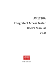
Model
H-4271
1-Watt Spread Spectrum Data modem
Owner's Manual
Version 1.0
D E S I G N
75 West 100 South, Logan, Utah 84321
A N A L Y S I S
Phone: (435) 753-2212
A S S O C I A T E S ,
Fax: (435) 753-7669
I N C.
Web: http://www.waterlog.com E-mail: [email protected]
D E S I G N
75 West 100 South, Logan, Utah 84321
A N A L Y S I S
Phone: (435) 753-2212
A S S O C I A T E S ,
Fax: (435) 753-7669
I N C.
Web: http://www.waterlog.com E-mail: [email protected]
User Agreement/
WATERLOG® Warranty
1. NATURE OF THE PRODUCT
This agreement accompanies an interface module comprising firmware, circuitry and other electronic
equipment in an enclosed housing, and packaged together with written instructional materials. The
packaged electronic circuitry and instructional materials herein are collectively referred to as the
“PRODUCT.” The PRODUCT is made available from DESIGN ANALYSIS ASSOCIATES, INC., of
75 West 100 South, Logan, Utah 84321 (hereinafter referred to as “DESIGN ANALYSIS”), and contains
information and embodies technology that is confidential and proprietary to DESIGN ANALYSIS, and
the availability and use of the PRODUCT is extended to you, the USER, solely on the basis of the terms
of agreement which follow.
2. ACKNOWLEDGMENTS BY USER
Opening the package which encloses the accompanying PRODUCT indicates your acceptance of the
terms and conditions of this agreement and constitutes an acknowledgment by you of the confidential and
proprietary nature of the rights of DESIGN ANALYSIS in the PRODUCT.
3. DUTIES OF YOU, THE USER
In consideration for the access to and use of the PRODUCT extended to you by DESIGN ANALYSIS
and to protect the confidential and proprietary information of DESIGN ANALYSIS, USER agrees as
follows:
(a) USER agrees that they will not remove from the exterior of the housing of the PRODUCT any
safety warnings or notices of proprietary interest placed thereon by DESIGN ANALYSIS.
(b) USER agrees that they shall not disassemble or otherwise reverse engineer the PRODUCT.
(c) USER agrees to treat the PRODUCT with the same degree of care as USER exercises in relation to
their own confidential and proprietary information.
4. TERM
USER may enjoy these rights only as long as their possession of the PRODUCT shall continue to be
rightful. These rights will cease if the PRODUCT is returned to DESIGN ANALYSIS under the terms of
any redemption offer, warranty, or money-back guarantee, or if USER transfers the PRODUCT to
another party on terms inconsistent with this agreement.
5. LIMITED WARRANTY
(b) What is Covered
DESIGN ANALYSIS warrants that for a period of twelve months from the time of purchase the
functions to be performed by the PRODUCT will be substantially in compliance with USER
documentation. DESIGN ANALYSIS also warrants that the PRODUCT will be free from
defects in materials and workmanship for a period of ONE YEAR from the date of purchase.
(b) What USER Must Do
If the product fails to satisfy the above warranty, USER must notify DESIGN ANALYSIS in
writing within the applicable period specified above and reasonably cooperate with the directions
they received from DESIGN ANALYSIS.
H-4271
User Agreement/WATERLOG® Warranty W-1
(c) What DESIGN ANALYSIS Will Do
DESIGN ANALYSIS will repair the PRODUCT or will endeavor to provide a replacement of
same within a reasonable period of time. In the event that DESIGN ANALYSIS is unable to
make the necessary repairs or replacement within a reasonable period of time, the original
purchase price will be refunded upon the return of the PRODUCT to DESIGN ANALYSIS.
(d) Limitations
(i)
THE ENTIRE REMEDY FOR BREACH OF THIS LIMITED WARRANTY SHALL
BE LIMITED TO REPLACEMENT OF THE DEFECTIVE PRODUCT OR
REFUNDING OF THE PURCHASE PRICE, AS SET FORTH ABOVE. IN NO
EVENT WILL THE LIABILITY OF DESIGN ANALYSIS TO USER OR TO ANY
OTHER PARTY EXCEED THE ORIGINAL PURCHASE PRICE OF THE PRODUCT,
REGARDLESS OF THE FORM OF THE CLAIM.
(ii) EXCEPT FOR THE EXPRESS WARRANTIES ABOVE, DESIGN ANALYSIS
SPECIFICALLY DISCLAIMS ALL OTHER WARRANTIES, INCLUDING,
WITHOUT LIMITATION, ALL IMPLIED WARRANTIES OF MERCHANTABILITY
AND FITNESS FOR A PARTICULAR PURPOSE.
(iii) UNDER NO CIRCUMSTANCES WILL DESIGN ANALYSIS BE LIABLE FOR
SPECIAL, INCIDENTAL, CONSEQUENTIAL, INDIRECT, OR ANY OTHER
DAMAGES OR CLAIMS ARISING FROM THE USE OF THIS PRODUCT, THIS
INCLUDES LOSS OF PROFITS OR ANY OTHER COMMERCIAL DAMAGES,
EVEN IF ADVISED OF THE POSSIBILITY OF SUCH DAMAGES. IN NO EVENT
WILL DESIGN ANALYSIS BE LIABLE FOR ANY CLAIMS, LIABILITY, OR
DAMAGES ARISING FROM MODIFICATION MADE THEREIN, OTHER THAN
BY DESIGN ANALYSIS.
(iv) THIS LIMITED WARRANTY GIVES USER SPECIFIC LEGAL RIGHTS. USER
MAY ALSO HAVE OTHER RIGHTS WHICH VARY FROM STATE TO STATE.
SOME STATES DO NOT ALLOW LIMITATIONS ON HOW LONG AN IMPLIED
WARRANTY LASTS OR THE EXCLUSION OF INCIDENTAL OR
CONSEQUENTIAL DAMAGES, SO THOSE LIMITATIONS OR EXCLUSIONS
MAY NOT APPLY.
6. GOVERNING LAW
This Agreement and its validity and interpretation shall be governed by the laws of the State of Utah,
notwithstanding any choice of law rules of Utah or any other state or jurisdiction.
W-2 User Agreement/WATERLOG® Warranty
H-4271
Chapter 1
Introduction
1.0 Introduction
The WATERLOG® H-4271 is a 1-watt FHSS (Frequency Hopping Spread Spectrum) telemetry
modem. The modem transfers a standard asynchronous (RS-232) serial data stream and operates
within the ISM 900 MHz frequency band. Two or more H-4271 modules are required; one
connected to the data recorder and one located at each remote site.
The radio link uses modern frequency hopping spread spectrum telemetry radios. Spread
spectrum technology is highly secure and has good interference immunity. The radio operates in
the license-free, 900 Mhz ISM Band eliminating the need for any FCC licensing.
Key features:
! Low system cost
! 1.0mW to 1.0Watt power output
! 9 - 18VDC supply voltage
! Up to 14 mile operation with dipole antenna
! Supports point-to-point, point-to-multipoint and repeater operating modes
! Built in power management including “sleep & sniff” modes.
! No configuration necessary for standard point to point communication
! Free setup, configuration and test software.
1.1 Description
Internally the H-4271 modem employs an industrial 9XTend RF module manufactured by Digi
International Inc. In addition, the modem includes a high efficiency DC/DC converter, RS-232
transceiver and a power down circuit. Complete specifications and a user manual for the
9XTend OEM module are available at www.digi.com
1.2 Reliability
When properly configured and installed, the H-4271 telemetry data link will have good
performance. However, as with any radio apparatus, interference, noise and other factors can
corrupt communications. Retries and other schemes can help recover from corrupted data or lost
messages. If your application requires 100% accuracy or you cannot tolerate missing data scans
do not use a radio link.
1.3 LED Indicators
The H-4271 has two LED indicators, marked RxDat and TxDat. The green RxDat LED flashes
whenever a data packet is received. The yellow TxDat LED flashes whenever a data packet is
transmitted.
H-4271
Introduction 1-1
1.4 Configuration and Programming
The H-4271 can be ordered from the factory preprogrammed with certain configurations such as
“sleep & sniff master”, “sleep & sniff slave” or “repeater”. If desired the user can change the
transmit power or other settings depending on specific needs. In general the factory
preprogrammed modes configure the modems for point-to-multipoint communications.
Messages sent by the master are received by all of the slaves. With this scheme no addressing is
done by the radios themselves and the communication protocol must include an in-band
addressing protocol (such as SDI-12) where only one slave will attempt to respond to a specific
message.
The X-CTU is a Windows-based application designed to interact with the firmware files found
on Digi’s RF products and to provide a simple-to-use graphical user interface. X-CTU is
designed to function with all Windows-based computers running Microsoft Windows 98 SE and
above. X-CTU can be downloaded from Digi’s web site.
The 9XTend module can be configured using a terminal program and “AT” modem commands,
however, the X-CTU software is much more convenient. In addition the X-CTU software has
support for testing the complete radio link as described in Chapter 2.
1.5 Power Management
The H-4271 is often used with remote solar powered water and meteorological monitoring
stations. Such applications however, require special attention to power management. Be aware
the standby (receive) current of the H-4271 is 65mA and will require a very large solar panel if
continually powered. The 9XTend module features a Sleep & Sniff low power mode which can
be used to reduce the solar panel and gauge station battery requirements.
1.6 Power Mode Jumper
The end-plate has a 2-position jumper marked Auto and Always On. When the jumper is in the
Auto position, the transmitter power is controlled by the DSR input. When DSR input (pin-4) is
de-asserted, the transmitter and RS-232 transceiver are completely powered off. In this state the
H-4271 is in its lowest power condition and only draws 260uA or so. When the jumper is in the
Always On position the internal power switch is forced to the ON state.
Normally the power switch is only used with a master station where the modem is connected
directly to a data logger. The data logger can use the DSR input to explicitly control the power
state and can place the H-4271 in its lowest current state. The Auto mode should not be used
with a remote station in that the modem is continually powered off and would not be able to
receive packets.
Alternatively, the internal 9XTend module includes a “pin-sleep” feature which is also controlled
by the DSR input (pin-4). With this configuration the jumper is set to Always On and the
9XTend module is programmed to do its own power management. This configuration has the
advantage of better response in that the 9XTend module does not need to do a cold power up
each time. On the other hand, a disadvantage is that the RS-232 transceiver remains continually
powered.
1-2 Introduction
H-4271
1.7 Point to Point
By default the modems operate in a transparent mode. The modems act as a serial line
replacement. If multiple modems are installed, data transmitted by one modem is received by all
of the other modems within range. In this mode the standby (receive) power is 65mA typ. This
mode is often used with SCADA applications where AC power is available and power is not of
concern.
1.8 Sleep and Sniff
Sleep & Sniff is a power management scheme normally used for solar panel powered systems.
With Sleep & Sniff one modem is configured as a Master and is connected to the data logger.
One or more modems are configured as Slaves and are connected to the remote sensing sites.
With Sleep & Sniff both the master and slave station(s) normally operate in a low power state.
The slave stations periodically awaken and listen (sniff) for a beacon signal. In this mode the
slaves only draw 65mA for a few milliseconds every 4-seconds or so. The Sleep & Sniff interval
is programmable depending on the desired power profile and system response time. The Master
is configured to awaken via “serial port sleep” when it detects an inbound message from the data
logger. The master prefixes the transmission with a beacon signal which is detectable by the
slave modems. After sending the beacon for a (programmable) period, the master transmits the
data packet. The recommended setup configures the slaves with cyclic sleep = 4.0 seconds and
the Master wake-up initializer = 10 seconds. With this setup the slaves will have sufficient time
for two attempts to detect the beacon.
The protocol for Sleep & Sniff is implemented by the 9XTend module and requires no
intervention by the data logger other than the data logger must be patient. The first response
from the remote site will require 10 seconds or more. An inactivity timer setting can be used to
keep both the master and slaves awake for subsequent transmissions without the overhead of
sending a beacon for every transmission. Sleep & Sniff is workable with multiple slave stations.
However, the communication protocol must include an in-band addressing scheme (such as SDI12) where only one slave will attempt to respond to a specific message.
With Sleep&Sniff operation a fault condition can occur is where the slave fails to detect the
beacon. If subsequent retry messages are sent they will also fail because the slave is asleep. The
data logger should issue retries by either waiting for the “time before sleep” inactivity timer to
expire before sending a retry or by forcing the retried message to be sent with a beacon. This can
be done by using the ATFH (force wake-up initializer) command. See Chapter 2 for a driver
which implements retries.
H-4271
Introduction 1-3
1.9 Repeater (Mesh)
The 9XTend module supports communication topologies which employ repeaters. When
configured as a repeater, a node re-sends RF data unless the transmission is addressed to it or if
the transmission has already been detected. A ‘repeater end node” handles repeated messages but
will not repeat the message over the air. Repeater topologies require careful design and setup of
the system. Repeaters will NOT work with Sleep & Sniff in that all nodes must be continually
powered . The recommenced setting is ATMD=5 (repeater). This setup allows all of the nodes
in the system be configured identically.
1.10 SDI-12 Gateway
Applications often arise where a SDI-12 sensor must be physically located hundreds or thousands
of feet from the data logger. Transparent wireless SDI-12 bridges are available for these
applications. Unfortunately, transparent bridges can miss or drop measurements because of
corrupted radio packet transmissions. Wireless bridges are problematic because the SDI-12
protocol provides insufficient time to make retries or other recovery.
When coupled with a H4271 data radio, a H-4191 module can be used to construct a “non
transparent” wireless SDI-12 link. With this architecture the H-4191 is permanently connected to
one or more sensors at the remote site. A pair of RS-232 data radios such as the H-4271 are
installed between the data logger and the remote H-4191. The data logger must be setup to
initiate and collect SDI-12 commands/responses from a RS-232 port instead of its normal SDI-12
port. SDI-12 commands from the data logger are forwarded via the radios to the remote H-4191.
When the remote data radio receives an inbound data packet, it pulses the CTS input of the H4191 which awakens the H-4191 in preparation to receive the inbound message. When the H4191 detects the “!” character, it transmits the contents of its buffer to the remote SDI-12 bus in a
contiguous frame with proper parity and bus timing. The H-4191 waits for and collects any
sensor response and forwards it to the radio. The sensor response is sent over the radios back to
the data logger. If one or more of the radio transmissions is lost or corrupted, the data logger can
retry the entire sequence as needed.
H-4191 RS-232 to SDI-12 Interface
1-4 Introduction
H-4271
The H-4191 has an internal inactivity timer which keeps the module awake to process the service
request and receive subsequent packets from the radio. If both the RS-232 and SDI-12 ports
become inactive (and both CTS and RTS are not asserted) for longer than 10-seconds, the timer
expires and the H-4191 enters its low power sleep mode. The H-4191 examines the
“aTTTN<CR><LF>” sensor response initiated by an “aM!” measure command and initializes a
second “keep-awake” timer to TTT + 3-seconds. This ensures the H-4191 will remain awake to
process the service request. When the service request actually arrives, the keep-awake timer is
zeroed. While the keep-awake timer is running the H-4191 sends a null (00h) to the radio
once/second to keep the radio link awake while waiting for the service request. The data logger
must discard the 00h characters.
When using a H-4191 SDI-12 gateway, the data logger must prefix all messages with four or five
0xFF characters to allow the H-4191 to awaken before the message payload arrives. The H-4191
automatically discards 0xFF characters such that they are not passed on to the SDI-12 sensor.
The radios used in this architecture are normally programmed for “sleep & sniff” low power
operation. When properly configured, the data logger, radios and H-4191 module can provide a
low-power wireless SDI-12 bridge capable of performing retries.
1.11 FCC Restrictions
This equipment has been tested and found to comply with the limits for a Class B digital device,
pursuant to Part 15 of the FCC Rules. These limits are designed to provide reasonable protection
against harmful interference in a residential installation. This equipment generates, uses, and can
radiate radio frequency energy and, if not installed and used in accordance with the instructions,
may cause harmful interference to radio communications. However, there is no guarantee that
interference will not occur in a particular installation. If this equipment does cause harmful
interference to radio or television reception, which can be determined by turning the equipment
off and on, the user is encouraged to try to correct the interference by one or more of the
following measures:
! Reorient or relocate the receiving antenna.
! Increase the separation between the equipment and receiver.
! Connect the equipment into an outlet on a circuit different from that to which the receiver is
connected.
! Consult the dealer or an experienced radio/TV technician for help
1.12 Agency Certifications
The 9Xtend RF module complies with Part 15 of the FCC rules and regulations. Compliance
with the labeling requirements, FCC notices and antenna usage guidelines is required by the
system integrator. The 9XTend module may only be used with antennas that have been tested an
approved for use with this module.
H-4271
Introduction 1-5
1-6 Introduction
H-4271
Chapter 2
Installation
2.1 General Installation Recommendations
The enclosure and connectors are not weather tight. The H-4271 must be installed in a protected
location or a weather tight enclosure. The housing has a 2-terminal connector for making power
connections and a 9-terminal DB-9 connector for the RS-232 port.
Caution:
Remove all power from the unit before making any connections.
2.2 Power Connection
Connect the +12V and GND terminals to a 12V power
source. Even though the H-4271 normally operates in a
low power mode, the transmitter requires 500mA for short
bursts. Make certain your wiring and battery is capable of
supplying sufficient current.
2.3 Data Connector
The H-4271 has a standard 9-pin RS-232 connector and is a DCE (modem) device. Connect the
RS-232 port to the serial port of your personal computer or other host device with a standard 9pin RS-232 cable. No gender changes or null-modem adapters are needed.
Program your host device for 9600 baud, 8-bit, no parity, full-duplex communication.
RS-232 Connector
Pin
Name
Direction
Description
Function
1
nc
2
TxD
Output
Transmit Data
Transmit data to host device
3
RxD
Input
Receive Data
Receive data from host device
4
DSR
Input
Data Set Ready
Awakens the H-4271 when asserted.
5
GND
Ground
Ground
6
DTR
Data Terminal
Ready
Internally connected to Pin-4
7
CTS
Input
Clear To Send
Connected to the GPI1/RTS
pin of the 9Xstream module
8
RTS
Output
Request To Send
Connected to the GPO1/CTS output
pin of the 9Xstream module
9
nc
not used
not used
H-4271
Installation And Maintenance 2-1
2.4 Power Mode Jumper
The end-plate has a 2-position power mode jumper
marked Auto and Always On. For most applications
install the jumper in the “Always On” position. See
Chapter 1.
2.5 Connecting The Antenna
Warning: When operating at a 1-Watt power output, observe a minimum separation of 2-feet
(0.6m) between radio modules. Transmitting in close proximity of other modules can the
damage the front end circuitry of the modules.
RF Exposure Warning: This equipment is approved only for mobile and base station
transmitting devices. It is not tested for “portable” applications. Antenna(s) used for this
transmitter must be installed to provide a separation distance of at least 30cm from all persons.
The power output is emitted at the antenna terminal and can be adjusted from 1 milliwatt to 1
Watt. This is an RF module approved for limited modular use operating as a mobile transmitting
device with respect to Section 2.1091 and is limited to integrator installation for mobile and fixed
applications only (it is not approved for portable applications). Professional installation
adjustment is required for setting module power and antenna gain to meet EIRP compliance for
high gain antenna(s).
FCC regulations stipulate a maximum 36 dBm EIRP power limitation. Users implementing
antenna gain greater than 6.0 dB must compensate for the added gain with cable loss. When
operating at 1-Watt power output, the sum (in dB) of cable loss and antenna gain shall not exceed
6.0 dB.
The H-4271 must be used with a 50-ohm, 900 MHz antenna. The antenna connector is a
RPSMA (Reverse-polarity SMA) connector which is required to meet FCC regulations.
A simple vertical whip antenna will work up to 2 or 3 miles. Longer distances require a
directional antenna with gain. A 6dB YAGI will work fine, do not use a 12dB model. Please
refer to the Antennal Options section of the Digi 9XStream product manual for approved
antennas for use with this module.
At 900 MHz, RG58 type coaxial antenna feed lines have excessive loss (1.8dB/10 feet).
Consider using newer low loss RF cable such as Times Microwave LMR-400 or similar
(0.8dB/10 feet). The LMR-400 requires special RG8 connectors.
2-2 Installation And Maintenance
H-4271
2.6 Words of Caution
Successful operation can depend on may factors. Multipath, interference and other site specific
problems can make a radio link unworkable. After installation it is highly recommended to test
the link with the Digi’s X-CTU software utility as explained at the end of this chapter. When
multipath conditions exist simply moving one of the antennas a few feet can make a difference.
In general, use low-loss antenna cable, a high quality antenna and mount the antenna as high
above the earth as possible. 900MHz signals require line-of-sight operation and generally will
not propagate around hills or other large obstructions. A wise system integrator will perform a
preliminary site test to see if the link is workable before permanently installing the equipment.
! Even though the H-4271 operates in a low power mode, the transmitter requires 500mA for
short bursts. Make certain your wiring and battery is capable of supplying sufficient current .
! Keep the antenna cable as short as possible.
! Use low-loss antenna cable
! Install a lightening protection device on the antenna cable
! Connect the modem case to a good earth ground
! Protect any exposed antenna connectors from water and corrosion
2.7 Modem Configuration
The following sections document the modem configurations for several specific applications
available from the factory. These settings can be checked or changed with either “AT”
commands or with use of Digi’s X-CTU Windows-based application as described in Chapter 1.
General configuration notes:
!
!
!
!
!
!
All radios are setup for 9600 baud
Set the destination address for all radios to the same unique value (Design Analysis
Associates uses: ATDT=DCBA)
A master configured for Sleep&Sniff is workable with a slave which is not configured with
Sleep&Sniff (the slave ignores the beacon)
Set ATCS=1 in the slave radios so RTS will awaken the H-4191 module when used
Set ATCD=0 so the RxDat LED will work
The ATRO and ATMD commands have different settings between the 9Xstream and
9XTend models
H-4271
Installation And Maintenance 2-3
2.7.1 Generic (works with the H424 transparent SDI-12 bridge)
+++<CR>
*ATRE
*ATBD
*ATNB
*ATPL
*ATCD
*ATCS
*ATSM
*ATDT
*ATWR
*ATCN
activate AT mode
restore defaults
3
9600 baud
0
no parity
4
1-watt
0
GPO2 = RxDat LED
1
assert RTS while receiving data
1
pin sleep via DSR input
DCAB set the modem address
write setttings
cancel AT mode
2-4 Installation And Maintenance
H-4271
2.7.2 Sleep&Sniff Master
+++<CR>
ATRE
ATBD
ATNB
ATPL
ATCD
ATCS
ATSM
ATDT
ATRO
ATST
ATHT
ATLH
ATWR
ATCN
activate AT mode
restore defaults
3
9600 baud
0
no parity
4
1-watt
0
GPO2 = RxDat LED
1
assert RTS while receiving data
2
serial port sleep
DCAB set the networking address
10
packetization timeout, 16 x 1/9600 x 10 = 16.6 ms
[1/1200 x 10 = 8.3ms]
assures data will arrive in contiguous packets
64
time before sleep (inactivity timer) 100 x .1= 10 seconds
50
time to beacon = 80 x .1 = 8.0 seconds
64
wakeup initializer (beacon) transmit time, 100 x 0.1 = 10.0 seconds
write setttings
cancel AT mode
2.7.3 Sleep&Sniff Slave
+++<CR>
ATRE
ATBD
ATNB
ATPL
ATCD
ATCS
ATSM
ATDT
ATRO
ATST
ATWR
ATCN
activate AT mode
restore defaults
3
9600 baud
0
no parity
4
1-watt
0
GPO2 = RxDat LED
1
assert RTS while receiving data
6
cyclic, 4.0 second sleep
DCAB set the networking address
10
packetization timeout, 16 x 1/9600 x 10 = 16.6 ms
[1/1200 x 10 = 8.3ms]
assures data will arrive in contiguous packets
64
time before sleep (inactivity timer) 100 x .1= 10 seconds
write setttings
cancel AT mode
H-4271
Installation And Maintenance 2-5
2.7.4 Repeater
These settings configure the radio for repeater operation. With repeaters, sleep&sniff will not
work. All radios in the network must be continually powered. With these settings any radio can
be a repeater, master, or a slave. Each module must have a unique MY (Source Address)
parameter. These settings are for Broadcast communications - each packet comes out every node
exactly once.
Step 1. Program radio with custom modem settings
+++<CR>
ATRE
ATBD
ATNB
ATPL
ATCD
ATCS
ATDT
ATRN
ATPK
ATRB
ATRO
ATMD
ATWR
ATCN
activate AT mode
restore defaults
3
9600 baud
0
no parity
4
1-watt
0
GPO2 = RxDat LED
1
assert RTS while receiving data
DCAB set the networking address
1
delay slots, repeaters may be in reach of each other
100
max packet size = 256 bytes
FF
packetization threshold = 255 bytes
10
packetization timeout, 16 x 1/9600 x 10 = 16.6 ms
[1/1200 x 10 = 8.3ms]
assures data will arrive in contiguous packets
5
repeater
write settings
cancel AT mode
Step 2. Set the “MY” address for each radio
+++<CR>
ATAM
ATWR
ATCN
Activate the AT mode
autoset the address
write the new setting
cancel AT mode
2-6 Installation And Maintenance
H-4271
2.8 Testing and Troubleshooting
You can test radio link by connecting a laptop computer to one radio and installing a loop-back
connector on the other radio. With this configuration, one person can test both up-link and downlink communication paths while aligning or testing the antennas.
Run a serial communications program such as Xtalk, Hyperterminal or Simpleterm on the
computer. Connect the local radio to the laptop computer with a standard 9-pin RS-232 cable.
Make sure your computer or terminal is set for full-duplex, 9600 Baud. If the Mode jumper is set
to “auto”, the communications program must assert the DSR input signal to the H-4271 to
awaken it from sleep.
The radios have a female DB9 connector, pin-2 is received data output and pin-3 is transmit data
input. Configure the remote radio for “loopback” operation by installing a DB9 connector with
pins 2 &3 connected together.
The radio link is essentially a full-duplex connection, depending on the settings of your terminal
program you may or may not be able to see what you are typing on your screen. Test the radio
link by typing characters and checking for the proper echoed response. As you type, the
characters are transmitted to the remote station then re-transmitted back to the local station and
displayed on your screen. Both up-link and down-link paths are tested at the same time.
A much more productive test is to use Digi’s X-CTU software utility. To use this test select the
“Range Test” menu and “Start” the test. This automated test sends repeated packets and
maintains a history of good and bad packets. It shows the communications data and displays a
real time reading of the percent of good packets.
H-4271
Installation And Maintenance 2-7
2.9 Example Sleep&Sniff Host Driver
/*
* **************************************************************
* Subroutine: SDI_Send_Command_RS232(int port, int radio)
*
* Description: Send an SDI-12 command out the selected serial port
*
This is an upper level routine that
*
handles sending breaks and retries.
*
* Inputs:
port = com port 1, 2, or 3
*
radio = yes or no
*
Changes the time outs and
*
wakes up the radios
*
* Return:
char 0 = error
*
!0 = ok, sensor address
*
* **************************************************************
*/
@far char SDI_Send_Command_RS232(int port, int radio)
{
char Data;
char c;
int
Timeout;
int
i;
char buffer[50];
char retry;
if(port == MainPort)
return(0);
// Port is in use for the menu or command mode
// so just return with an error
//
// start of retry loop
//
Data = 0;
retry = SDIBreakRetry + 1;
// default to no response
// each retry will cause a break on the H-4191
do
{
EnableComPort(port,9600);
// Turn on the RS232 drivers
if(radio)
{
putcharX(port,0xFF);
putcharX(port,0xFF);
putcharX(port,0xFF);
putcharX(port,0xFF);
putcharX(port,0xFF);
putcharX(port,0xFF);
putcharX(port,0xFF);
}
// if a radio connection is selected
// then send radio preamble
// It may take up to 4 to wake the remote 4191
// the first few chars are lost because 4191
// is waking up during first few chars
// send the command
printstringX(port,SDI_Out_buffer);
// wait xx seconds for the command
// Use a little longer delay for the radio mode
// The delay is not exact as overhead extends the loop
if(radio)
Timeout = 6500;
else
Timeout = 1500;
// 6.5 second delay between retries
// 1.5 second delay
do
{
msdelay(1);
if(port == 1)
if(COM1_LastChar == 0x0A)
Timeout = 0;
2-8 Installation And Maintenance
// CR LF terminates the response
H-4271
if(port == 2)
if(COM2_LastChar == 0x0A)
Timeout = 0;
// CR LF terminates the response
if(port == 3)
if(COM3_LastChar == 0x0A)
Timeout = 0;
// CR LF terminates the response
if(Timeout)
Timeout--;
}
while(Timeout);
for(i = 0 ; i < 50 ; i++)
{
getcharX(port, 0, &Data);
Data = Data & 0x7F;
SDI_In_buffer[i] = Data;
if(Data == 0)
break;
// move response to SDI In Buffer
// strip off parity bit
// save in SDI buffer
}
// make sure in buffer is empty before leaving
// do it quick so we do not get the service request
while(getcharX(port, 0, &c));
// look for proper SDI-12 address and return it or return a NULL
if(SDI_In_buffer[0] >= ' ')
Data = SDI_In_buffer[0];
else
Data = 0;
if((retry == 4) && (!Data) ||
(retry == 2) && (!Data))
{
msdelay(2000);
if(radio)
{
putcharX(port,'+');
putcharX(port,'+');
putcharX(port,'+');
msdelay(2000);
// Only send the radio beacon
// on selected retries
// if a radio connection is selected
// +++
// wait for 'OK'
putcharX(port,'A');
putcharX(port,'T');
putcharX(port,'F');
putcharX(port,'H');
putcharX(port,',');
putcharX(port,'C');
putcharX(port,'N');
putcharX(port,0x0A);
putcharX(port,0x0D);
//
//
//
//
//
This command forces the
radio to resend the beacon
to the remote radio.
now making this part of
the retry process
msdelay(2000);
// wait for 'OK'
}
while(getcharX(port, 0, &c));
// start with a clear buffer
}
}
while((--retry) && (!Data));
return(Data);
}
H-4271
Installation And Maintenance 2-9
2-10 Installation And Maintenance
H-4271
Appendix A
Specifications
Radio
Frequency Range:
Spread Spectrum:
Modulation:
Channel Capacity
Transmission Power:
Receive Sensitivity:
Indoor/Urban Range
Outdoor
RF line-of-sight
Antenna Impedance
Certifications
902 to 928 Mhz
Frequency Hopping
FSK
10 hop sequences share 50
frequencies
1mW - 1Watt
-110 dBm
Up to 3000' (900m)
Up to 14 miles w/ dipole
antenna
Up to 40 miles w/ high-gain
antenna
50 ohms
FCC Part 15.247
Environmental
Operating Temperature:
Storage Temperature:
Humidity:
Mechanical
Enclosure:
Size:
Connectors
Antenna:
Data:
Power:
-40 to 85EC
-40 to 85EC
Non condensing
Anodized Aluminum
2.75 x 1.125 x 3.60 in.
RPSMA (reverse SMA)
DB9S
Phoenix 1803277 (header)
Phoenix 1803578 (plug)
(2-position 3.81mm)
The RF module has the following FCC approval:
Serial Port
Type:
Data Rate:
RS-232 (DCE)
9600 bps
Power Requirements
Voltage Input:
9.0 to 18.0 Volts DC
Power Control:
* Always on
* Sleep & Sniff
* Host controlled via DSR
FCC ID: OUR-9XTEND
IC#: 4214A-9XTEND
Warranty
The WATERLOG® H-4271 is warranted against defects
in materials and workmanship for one year from date
of shipment.
Current (@12.0V, jumper = auto):
Standby:
260uA
Receive:
65 mA
Transmit:
450 mA
Current (@12.0V, jumper = always on):
Receive:
60 mA
Transmit:
450 mA
H-4271
Specifications A-1
2-2 Installation And Maintenance
H-4271