1
1-66 Chapter 1
NC-AFM, IC-AFM, and MFM Imaging
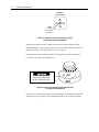
For vibrating-cantilever AFM methods, the cantilever is mounted in a specific type of
cartridge, referred to as a non-contact cartridge. The non-contact cartridge has a thin
piezoelectric actuator (a piezoelectric transducer) sandwiched between the cartridge and
the cartridge mount. Between the two prongs of the cartridge there is a layer of gray
material directly under the cartridge mount. This layer is the actuator.
When an AC voltage signal is applied to the actuator, the actuator oscillates: it expands
and contracts. The oscillations cause a cantilever mounted on the cartridge to vibrate
with the same frequency as the AC signal.
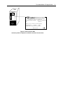
On the underside of the cartridge (the side with the spring clip), there is also a small red
wire. This wire delivers the AC voltage signal to the actuator. The signal is delivered via
a copper contact on the top surface of the cartridge, which makes contact inside the NCAFM probe head. Near the opposite corner of the cartridge is another contact, which
grounds the cartridge when it makes contact inside the probe head.
The AC signal, or driving signal, that causes the cantilever to oscillate with a constant
frequency, is generated by the sine wave generator. The sine wave generator is located
on the frequency synthesizer board installed in the AEM. The drive frequency can be
varied and is chosen to lie close to the cantilever’s resonant frequency. The amplitude of
the driving signal can also be adjusted to maximize the vibration amplitude of the
cantilever far from the sample surface.
The AC signal from the sine wave generator is also input to the lock-in amplifier to
provide the reference signal for lock-in detection.
Motions of the oscillating cantilever are measured by the deflection sensor, located in the
NC-AFM probe head. The deflection sensor includes a laser, a mirror that reflects the
laser beam onto the back of the cantilever, and a position-sensitive photodetector (PSPD).
Both the frequency and the amplitude of cantilever vibration are monitored as changes in
the position of the laser spot incident on the PSPD. For MFM operation, the DC
component of the PSPD signal is read in addition to the AC component, and it can be
used to generate an MFM image. This cantilever detection scheme is often referred to as
the laser beam-bounce technique.
The AC signal from the PSPD is sent to a lock-in amplifier. The lock-in amplifier is a
very narrow bandpass filter which is used to detect an AC signal at a specific frequency
and output a DC signal proportional to its amplitude. The frequency “locked-in” for
detection is set by the reference signal from the sine wave generator.