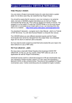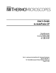
1
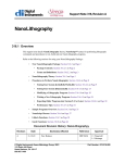
Nanolithography for Explorer
v. 1.0
Software User’s Manual
ThermoMicroscopes
1171 Borregas Avenue
Sunnyvale, California
94089
Tel: (408) 747-1600
Fax: (408) 747-1601
85-10331 Rev. A
Binary License Agreement
You, the Licensee, assume responsibility for the selection of the program to achieve your intended results, and for the installation, use, and results obtained from the program.
IF YOU USE, COPY, MODIFY, OR TRANSFER THE PROGRAM, OR ANY COPY, MODIFICATION, OR MERGED PORTION, WHOLE OR PART EXCEPT AS EXPRESSLY PROVIDED FOR IN THIS LICENSE, YOUR LICENSE IS AUTOMATICALLY TERMINATED.
LICENSE
You may:
•
Use the program on a single machine and copy the program into any machine-readable or printed form for backup or
support of your use of the program on the single machine.
•
Modify the program and/or merge it into another program for your use on the single machine. Any portion of the
program merged into another program will continue to be subject to the terms of this Agreement. You must reproduce
and include the copyright notice on any copy, modification, or portion merged into another program.
•
Transfer the program and license to another party within your organization if the party agrees to accept the terms and
conditions of this Agreement. If you transfer the program, you must at the same time either transfer all copies, whether
in machine readable form or printed form, to the same party or destroy any copies not transferred; this includes all
modifications and portions of the program merged into other programs. You may not transfer the program to a party
outside of your organization without the express written permission of ThermoMicroscopes.
TERMS
The license is effective on the date you take delivery of the software as purchased from ThermoMicroscopes, and remains in
effect until terminated as indicated above or until you terminate it. If the license is terminated for any reason, you agree to
destroy or return the program together with all copies, modifications, and merged portions in any form.
COPYRIGHT NOTICE—COVERS ALL ATTACHED DOCUMENTATION
© ThermoMicroscopes Corporation 2001. All rights reserved.
ThermoMicroscopes Corporation retains all ownership rights to this documentation and all revisions of the SPMLab and
Nanolithography for Explorer computer programs and other related software options.
Reproduction of any portion of this publication or any image depicted in this publication (except for archival purposes or for
the specific use of the program in conjunction with ThermoMicroscopes equipment) without prior written authorization of
ThermoMicroscopes is prohibited by law and constitutes a punishable violation of the law.
THERMOMICROSCOPES CORPORATION PROVIDES THIS PUBLICATION “AS IS” WITHOUT WARRANTY OF
ANY KIND, EITHER EXPRESSED OR IMPLIED, INCLUDING BUT NOT LIMITED TO THE IMPLIED WARRANTIES
OR CONDITIONS OF MERCHANTABILITY OR FITNESS FOR A PARTICULAR PURPOSE. IN NO EVENT SHALL
THERMOMICROSCOPES BE LIABLE FOR ANY LOSS OF PROFITS, LOSS OF BUSINESS, LOSS OF USE, LOSS OF
DATA, INTERRUPTION OF BUSINESS, OR FOR INDIRECT, SPECIAL, INCIDENTAL, OR CONSEQUENTIAL
DAMAGES OF ANY KIND EVEN IN THE EVENT OF SUCH DAMAGES ARISING FROM ANY DEFECT OR ERROR
IN THIS PUBLICATION OR IN THE SPMLab or Nanolithography for Explorer SOFTWARE.
Explorer, Nanolithography for Explorer, SPMLab, TrueMetrix, the TM logo, and ThermoMicroscopes are trademarks of
ThermoMicroscopes Corporation.
THERMOMICROSCOPES
You can find ThermoMicroscopes on the World Wide Web at http://www.thermomicro.com.
CORPORATE HEADQUARTERS
THERMOMICROSCOPES EUROPE
THERMOMICROSCOPES UK
ThermoMicroscopes
1171 Borregas Avenue
Sunnyvale, CA 94089
USA
ThermoMicroscopes Europe
48, rte des Acacias
CH-1227 Acacias (Geneva)
Switzerland
ThermoMicroscopes UK
4A Minton Place
Victoria Road
Bicester OX6 7QB, United Kingdom
Tel: 408.747.1600
Fax: 408.747.1601
E-mail: [email protected]
Tel: (+41) 22 300 44 11
Fax: (+41) 22 300 44 15
E-Mail: [email protected]
Tel: (+44) 01869 252544
Fax: (+44) 01869 327744
E-mail: [email protected]
THERMOMICROSCOPES PRODUCT WARRANTY COVERAGE
ThermoMicroscopes warrants that products manufactured by ThermoMicroscopes will be free of defects in materials and
workmanship for one year from the date of shipment. The product warranty provides for all parts (excluding consumables,
maintenance items, and PCs), labor, and software upgrades.
Instruments, parts, and accessories not manufactured by ThermoMicroscopes may be warranted by ThermoMicroscopes for
the specific items and periods expressed in writing on published price lists or quotes. However, all such warranties extended
by ThermoMicroscopes are limited in accordance with all the terms, conditions, and other provisions stated in this warranty.
ThermoMicroscopes makes no warranty whatsoever concerning products or accessories not of its manufacture except as noted
above.
Customers outside the United States and Canada should contact their local ThermoMicroscopes representative for warranty
information appropriate to their locale.
CUSTOMER RESPONSIBILITIES
1.
Use ThermoMicroscopes replacement parts.
2.
Use ThermoMicroscopes or ThermoMicroscopes-approved consumables, such as lamps, cantilevers, filters, etc.
3.
Provide adequate and safe working space around the products for servicing by ThermoMicroscopes personnel.
REPAIRS AND REPLACEMENTS
ThermoMicroscopes will, at its option, either repair or replace defective instruments or parts. Repair or replacement of
products or parts under warranty does not extend the original warranty period. With the exception of consumable and
maintenance items, replacement parts or products used on instruments out of warranty are themselves warranted to be free of
defects in materials and workmanship for 90 days. Any product, part, or assembly returned to ThermoMicroscopes for
examination or repair must have prior approval from ThermoMicroscopes and be identified by a Return Materials
Authorization (RMA) number obtained before returning the product. The product, part, or assembly must be sent freight
prepaid to the factory by the Customer. Return transportation to the customer will be at ThermoMicroscopes' expense if the
product, part, or assembly is defective and under warranty.
Nanolithography for Explorer
WARRANTY LIMITATIONS
This warranty does not cover: a) Parts and accessories which are expendable or consumable in the normal operation of the
products. b) Any loss, damage, and/or product malfunction resulting from shipping or storage, accident, abuse, alteration,
misuse, or use of user-supplied software, hardware, replacement parts, or consumables other than those specified by
ThermoMicroscopes. c) Products which are not properly installed. d) Products which are not operated within the specified
environmental conditions. e) Products which have been modified or altered without written authorization from
ThermoMicroscopes. f) Products which have had the serial number altered or removed. g) Improper or inadequate care,
maintenance, adjustment, or calibration by the user.
SERVICE
To contact the service department directly with service-related issues or questions, you can reach service personnel Monday
through Friday, 8:00 am-5:00 pm, Pacific Standard Time (voice mail is available 24 hours).
Within the USA and Canada: 800-727-5782
Outside the USA and Canada: 408-744-3001
Fax: 408-747-1601
e-mail: [email protected]
When contacting the service department, it is helpful if you have the model and purchase order numbers available.
Table of Contents
Preface . . . . . . . . . . . . . . . . . . . . . . . . . . . . . . . . . . . . . . . . . . . . . . . .v
Chapter 1 Installation . . . . . . . . . . . . . . . . . . . . . . . . . . . . . . . . . 1-1
Chapter 2 Nanolithography Operation . . . . . . . . . . . . . . . . . . . 2-1
Explorer Setup . . . . . . . . . . . . . . . . . . . . . . . . . . . . . . . . . . . . . . . . . . 2-2
Take an Image . . . . . . . . . . . . . . . . . . . . . . . . . . . . . . . . . . . . . . . . . . 2-3
Setting Lithography Parameters . . . . . . . . . . . . . . . . . . . . . . . . . . . . . 2-4
Draw a Pattern . . . . . . . . . . . . . . . . . . . . . . . . . . . . . . . . . . . . . . . . . . 2-6
Write a Pattern . . . . . . . . . . . . . . . . . . . . . . . . . . . . . . . . . . . . . . . . . . 2-8
Take a Confirmation Scan . . . . . . . . . . . . . . . . . . . . . . . . . . . . . . . . . 2-8
Image Processing . . . . . . . . . . . . . . . . . . . . . . . . . . . . . . . . . . . . . . . . 2-8
Zoom . . . . . . . . . . . . . . . . . . . . . . . . . . . . . . . . . . . . . . . . . . . . . . . . . 2-8
Appendix: Hardware Setup for Nanolithography By Bias
Nanolithography for Explorer
CH APTE R
Preface
INTRODUCTION
The ThermoMicroscopes Nanolithography for Explorer software is a stand-alone package
that was developed using the SPMTools software package and serves as a demonstration of
a custom software application that can be developed using SPMTools. This program can
be customized using SPMTools and the necessary source code.
Nanolithography for Explorer allows you to use your Explorer instrument to develop lithography techniques specific to your application, e.g., modifying a photoresistive surface
that has been deposited on a substrate. It is a data acquisition program that loosely
resembles SPMLab 5.01, however it is not a general purpose SPM software package. As
it is geared toward lithography, its SPM capability is limited, e.g., it is not possible to
acquire multiple images in a single scan.
This manual guides you through the basic steps of how to write a pattern on a sample using
Nanolithography for Explorer with an Explorer system. It only describes those features
that are unique to Nanolithography for Explorer, as many features and screen controls are
identical to SPMLab 5.01.
This manual assumes that you are familiar with the SPMLab software and your Explorer
system, and that you know how to operate in AFM mode. If you are new to Explorer or
SPMLab, refer to the appropriate user manual.
OPERATING SAFETY
The safety warnings and caution statements in your Explorer Instrument Operation Manual
are valid when using the Nanolithography for Explorer package and should be read
carefully and strictly observed.
It is important that you are familiar with the principles of AFM operation, as lithography
involves a greater risk of causing damage to the sample, probe and scanner.
Nanolithography for Explorer
vi
CH APTE R
Chapter 1
Installation
To install and use Nanolithography for Explorer, SPMLab 5.0 or higher must be installed
on your computer.
Step 1
Insert the Nanolithography for Explorer CD into the CD ROM drive, and follow
the steps in the installation wizard.
Step 2
When prompted for initialization (.INI) files, point to the folder containing the
SPMLab files.
Step 3
When prompted for scanner files, point to the Scanners sub-folder in the folder
containing the SPMLab files.
NOTE SPMLab and Nanolithography for Explorer cannot be run simultaneously.
Nanolithography for Explorer
1-2
CH APTE R
Chapter 2
Nanolithography Operation
Figure 2-1
Nanolithography for Explorer main screen.
Nanolithography for Explorer
2-2
When the Nanolithography for Explorer program is launched, the main screen appears, as
shown in Figure 2-1. Many parts of the screen resemble the Data Acquisition mode of
SPMLab. When the program is launched for the first time, the values in the PARAMETERS
sub-panel will be copied from the last SPMLab session. The FEEDBACK value in the lower
left of the window represents the internal sensor signal. The line profile is displayed in the
lower right of the window when a scan is being taken.
The tool bar, shown in Figure 2-2, provides the tools for drawing a desired lithography
pattern, in addition to a few familiar tool bar buttons.
Figure 2-2
Tool bar.
The following basic steps will take you through a first lithography session. For future
sessions, note that Steps 2 and 6 are optional, and if a previously saved drawing pattern is
used, Steps 3 and 4 are also unnecessary.
1
Use SPMLab to set up your Explorer instrument to take an image, as described in the
Explorer Instrument User Manual.
2
Use the Nanolithography for Explorer program to take a topographic image of your
sample.
3
Set the lithography parameters in the WRITING CONDITION dialog box.
4
Draw shapes, lines or other marks using the drawing tools on the tool bar.
5
Load the saved drawing pattern and initiate lithography by clicking the DO LITHOGRAPHY
6
1
button
on the tool bar.
Perform a topographic scan of the sample to view the results of the lithography.
Step 1
EXPLORER SETUP
Mount a cantilever assembly and sample. The probe you use will depend on the
sample. E.g., using the Scratch method (see page 2-5), harder sample surfaces
require a stiffer cantilever to write a pattern.
A plastic CD or PMMA are recommended as test sample surfaces.
Step 2
If you are going to apply a bias to the tip (using the By Bias method—see page 25), refer to the Appendix, Hardware Setup for Nanolithography By Bias, at the end
of this manual.
Step 3
Close Nanolithography for Explorer, if it is open, and launch your SPMLab
software (the two programs cannot be run simultaneously). It is easier to make
sure the Setpoint is properly set in SPMLab than in the Nanolithography program.
Step 4
Align the laser, mirror, and photodetector.
Step 5
Bring the tip into feedback at the sample surface.
Step 6
Close SPMLab, and launch Nanolithography for Explorer.
NANOLITHOGRAPHY OPERATION
2
TAKE AN IMAGE
2-3
It is not necessary to take scan of your sample before writing a lithography pattern on it, but
it is a good idea to scan a few lines to make sure the surface is clean and flat (i.e., suitable
for lithography). Also, you may want to take a full scan in order to compare the sample
surface before and after writing a lithography pattern.
Step 1
Close SPMLab, if it is open, and launch Nanolithography for Explorer.
Step 2
Confirm the scan parameters in the PARAMETERS sub-panel. When the program
is launched, the values will be those used in the last session.
Step 3
To do non-contact operation, check the NONCONTACT box in the PARAMETERS
sub-panel. The SPECTRUM window opens, as shown in Figure 2-3.
Set up for non-contact operation as described in Chapter 2 of the SPMLab Software Reference Manual.
Figure 2-3
Step 4
Spectrum window.
Click the TIP APPROACH button to perform an approach.
Nanolithography for Explorer
2-4
Step 5
When the approach is finished, click ACQUIRE START to take an image.
You can stop the scan at any time by clicking ACQUIRE STOP, e.g., if you only
want to scan a few lines.
Step 6
3
SETTING
LITHOGRAPHY
PARAMETERS
If you want to save the image to use for comparison, select
FILE→SAVE IMAGE to open the SAVE AS dialog box.
The lithography writing parameters are selected in the WRITING
CONDITION dialog box, shown in Figure 2-4, which is accessed
by clicking on the OPTION menu.
Figure 2-4
Writing Condition dialog box.
NANOLITHOGRAPHY OPERATION
Step 1
2-5
Select one of the three lithography methods, as described below:
NOTE The By Bias method requires the MFM/EFM scanner (part number 5450-00) and
an EFM probe (part number 1600-00).
BY BIAS: With feedback on and the set point at its normal value, a voltage is
applied between the tip and the sample.
BY SETPOINT: With feedback on, a relative set point offset is added to the set
point so that a higher force is applied.
SCRATCH: With feedback off, a relative Z offset is added to the Z scanner to
move the tip closer to the surface.
Step 2
Enter a value in the WRITING CONDITION box that corresponds to the method you
have selected. Note that the system will ignore the values that correspond to the
other two methods (only one method can be used at a time). For the Scratch
method, a positive value in the RELATIVE Z HEIGHT box moves the probe closer
to the sample.
NOTE Softer samples require less force. For a given writing condition value, a stiffer
cantilever results in more force.
Step 3
Enter a value in
the SPEED box.
The best speed
will depend on
the surface property of your sample and the lithography method you are using.
Step 4
Enter a value in the DELAY box, if desired. This setting controls the length of time
the system will pause after you click the DO LITHOGRAPHY button and before
lithography begins. If the pattern consists of multiple components (e.g., a circle
and a square), the delay time also applies to the pause between the writing of each
component.
Step 5
If you want to
write a
registration
mark (a cross)
on your
sample, enter
values for the
position and
Nanolithography for Explorer
2-6
size of the registration mark, and click the WRITE REGISTRATION button to
initiate writing. Writing a registration mark is useful if you want to remove your
sample and then return to the area of the lithography at a later time. This can be
done at any time, as long as the tip is in feedback at the surface.
Step 6
4
DRAW A PATTERN
Click the OK or APPLY button to apply the current writing parameters to the
patterns you draw after clicking OK or APPLY. OK closes the dialog box; APPLY
leaves it open but still allows you to draw patterns. After you draw a pattern, you
can then enter new writing parameters, click OK or APPLY again, and add
components to your pattern that will be written with the new parameters. In this
way, a lithography pattern can have multiple components or groups of
components, each with its own writing parameters.
You can draw any combination of points, shapes and patterns. When using the drawing
tools, the position and size of the object you are drawing are displayed in the status bar at
the bottom of the window. If you have taken an initial scan of your sample and want to
draw a pattern at a particular location, use the zoom function, as described on page 2-8.
Step 1
Make sure you have clicked OK or APPLY in the WRITING CONDITION dialog
box so the current writing parameters will be applied to the pattern you draw.
Step 2
Use the tools to draw a pattern in the display as described in the following
sections.
Click on the Undo previous button
object.
to remove the most recently drawn
To erase all objects from the image, click on the Clear drawing button
POINTS, LINES AND
SHAPES
.
Step 3
To apply different writing parameters to various drawing components or groups of
components, change the parameters in the WRITING CONDITION dialog box, click
OK or APPLY, and then draw the additional components. These components will
use the new writing parameters. This process can be repeated.
Step 4
Save the drawing, if desired, by clicking on the SAVE DRAWING button
.
Drawings are saved in .dat format. Once saved, the drawing can be loaded at
any time to be written on this or other samples.
Step 1
Choose a drawing tool by clicking the appropriate
button on the tool bar.
Step 2
To draw a single point, use the Point tool to click on
the desired location, which will be marked by a “+”
sign in the display.
Step 3
Line
Point
Rectangle
To draw a line, rectangle or circle:
(a) Use the left mouse button to begin drawing.
(b) Release the left mouse button, and use the mouse to position the object.
(c) Click the right mouse button to anchor the final position.
Circle
NANOLITHOGRAPHY OPERATION
TEXT
2-7
Step 1
Select the Text tool
and click on the location in the image display where
the text is to begin (this point will define the upper left corner of the text area).
The GET TEXT dialog box opens.
Step 2
Type in the desired
text, and change the
scale if desired.
Each character is
30x30 pixels when
the Scale value =
1.00. The higher the
Resolution value (in
the Parameters subpanel), the smaller
the text will appear
in the display.
Step 3
PARALLEL LINES &
POINT ARRAY
Click OK. The text appears in the display.
The Parallel Lines tool allows you to write a series of parallel lines on the sample surface.
The Point Array tool allows you to write a two-dimensional array of points.
Step 1
Click on the PARALLEL LINES or POINT ARRAY button. The
PARALLEL LINE SETUP or POINT ARRAY SETUP dialog box opens:
Step 2
Enter values and make choices, and click OK. The pattern will appear in the
display.
Nanolithography for Explorer
2-8
5
Step 1
If necessary, click on the Load drawing button
to load a drawing into the
display (must be a .dat file). If you have just drawn a pattern, it is not necessary
to save it for the system to write it.
Step 2
Click the DO LITHOGRAPHY button
sample.
WRITE THE
PATTERN
6
TAKE A
CONFIRMATION
SCAN
to begin writing the pattern on your
You may want to take a topography scan of your sample to view the results of the lithography.
Step 1
If the tip is not in feedback, click the TIP APPROACH button to perform an
approach.
Step 2
When the approach is finished, click ACQUIRE START to take an image. While
the image is being taken, you can load the drawing into the display to use as a
comparison by clicking on the Load drawing button
.
Step 3
To view the original image (if you took one) or any other
image file, select FILE→OPEN IMAGE to access the OPEN
dialog box.
IMAGE
PROCESSING
Any images you take using Nanolithography for Explorer can be imported into the Image
Processing module of SPMLab.
ZOOM
The zoom function is useful if you are dissatisfied with the lithography pattern you have
written and want to write a new pattern at a different location on the sample, or if you have
taken a scan of your sample and want to define the region where the pattern will be drawn.
When using the zoom function, it is not necessary to be in feedback.
Click the ZOOM button to open the zoom function, shown in Figure 2-5. The box in the
upper left corner represents the maximum allowable zoom area. Use one of the three
following methods:
• Left-click on the blue box in the zoom box (in the upper left corner) and hold the
mouse button down to resize the scan area. Release the left mouse button, and use
the mouse to translate the scan area within the larger region. Right-click to anchor
the position and exit the zoom function.
• Apply the above method directly on the image in the display to the right.
• Enter values into the RANGE, X OFFSET and Y OFFSET boxes, and click APPLY
to confirm your scan area and exit the zoom function.
When you exit the zoom function, the tip moves to the new location.
NANOLITHOGRAPHY OPERATION
Figure 2-5
2-9
Zoom function.
Nanolithography for Explorer
2-10
Appendix:
Hardware Setup for
Nanolithography By Bias
The By Bias lithography method requires the MFM/EFM scanner (part number 5450-00)
and an EFM probe (part number 1600-00). With this hardware installed, make the connections shown in the figure below. Note also that this figure shows the necessary connections
for non-contact operation.
Explorer
Head
For Dithering Piezo
for Non-contact AFM
Black (Ground)
Green
Grey
Red
Sample
Mounting Disk
Black
Red
To Z Voltage Supply
on Explorer Head
Orange
MFM/EFM
Scanner
To Linearizer Plug
on Explorer Head
Nanolithography for Explorer