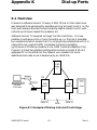
1
Series 8000 Xpress PSE
User Guide
(Software Version 9)
© Case Communications Ltd 1997
X890-304751 Issue 1
0-1
Unit 15, Riverside Business Centre, Victoria Street, High Wycombe, Bucks HP11 2LT
Web: www.casecomms.com
Email: [email protected]
Tel (UK): 08700 263 740
Tel (International): +44 (0) 1494 833 740
Fax (UK): 08700 263 741
Fax (International): +44 (0) 1494 833 741
Rev.1
aaaaaaaaaaaaaaaaaaaaaaaaaaaaaaaaaaaaaaaaaaaaaaaaaaaaaaaaaaaaaaaaaaaaaaaa
aaaaaaaaaaaaaaaaaaaaaaaaaaaaaaaaaaaaaaaaaaaaaaaaaaaaaaaaaaaaaaaaaaaaaaaa
aaaaaaaaaaaaaaaaaaaaaaaaaaaaaaaaaaaaaaaaaaaaaaaaaaaaaaaaaaaaaaaaaaaaaaaa
aaaaaaaaaaaaaaaaaaaaaaaaaaaaaaaaaaaaaaaaaaaaaaaaaaaaaaaaaaaaaaaaaaaaaaaa
aaaaaaaaaaaaaaaaaaaaaaaaaaaaaaaaaaaaaaaaaaaaaaaaaaaaaaaaaaaaaaaaaaaaaaaa
aaaaaaaaaaaaaaaaaaaaaaaaaaaaaaaaaaaaaaaaaaaaaaaaaaaaaaaaaaaaaaaaaaaaaaaa
aaaaaaaaaaaaaaaaaaaaaaaaaaaaaaaaaaaaaaaaaaaaaaaaaaaaaaaaaaaaaaaaaaaaaaaa
aaaaaaaaaaaaaaaaaaaaaaaaaaaaaaaaaaaaaaaaaaaaaaaaaaaaaaaaaaaaaaaaaaaaaaaa
aaaaaaaaaaaaaaaaaaaaaaaaaaaaaaaaaaaaaaaaaaaaaaaaaaaaaaaaaaaaaaaaaaaaaaaa
aaaaaaaaaaaaaaaaaaaaaaaaaaaaaaaaaaaaaaaaaaaaaaaaaaaaaaaaaaaaaaaaaaaaaaaa
aaaaaaaaaaaaaaaaaaaaaaaaaaaaaaaaaaaaaaaaaaaaaaaaaaaaaaaaaaaaaaaaaaaaaaaa
aaaaaaaaaaaaaaaaaaaaaaaaaaaaaaaaaaaaaaaaaaaaaaaaaaaaaaaaaaaaaaaaaaaaaaaa
aaaaaaaaaaaaaaaaaaaaaaaaaaaaaaaaaaaaaaaaaaaaaaaaaaaaaaaaaaaaaaaaaaaaaaaa
aaaaaaaaaaaaaaaaaaaaaaaaaaaaaaaaaaaaaaaaaaaaaaaaaaaaaaaaaaaaaaaaaaaaaaaa
aaaaaaaaaaaaaaaaaaaaaaaaaaaaaaaaaaaaaaaaaaaaaaaaaaaaaaaaaaaaaaaaaaaaaaaa
aaaaaaaaaaaaaaaaaaaaaaaaaaaaaaaaaaaaaaaaaaaaaaaaaaaaaaaaaaaaaaaaaaaaaaaa
aaaaaaaaaaaaaaaaaaaaaaaaaaaaaaaaaaaaaaaaaaaaaaaaaaaaaaaaaaaaaaaaaaaaaaaa
aaaaaaaaaaaaaaaaaaaaaaaaaaaaaaaaaaaaaaaaaaaaaaaaaaaaaaaaaaaaaaaaaaaaaaaa
aaaaaaaaaaaaaaaaaaaaaaaaaaaaaaaaaaaaaaaaaaaaaaaaaaaaaaaaaaaaaaaaaaaaaaaa
aaaaaaaaaaaaaaaaaaaaaaaaaaaaaaaaaaaaaaaaaaaaaaaaaaaaaaaaaaaaaaaaaaaaaaaa
aaaaaaaaaaaaaaaaaaaaaaaaaaaaaaaaaaaaaaaaaaaaaaaaaaaaaaaaaaaaaaaaaaaaaaaa
aaaaaaaaaaaaaaaaaaaaaaaaaaaaaaaaaaaaaaaaaaaaaaaaaaaaaaaaaaaaaaaaaaaaaaaa
aaaaaaaaaaaaaaaaaaaaaaaaaaaaaaaaaaaaaaaaaaaaaaaaaaaaaaaaaaaaaaaaaaaaaaaa
aaaaaaaaaaaaaaaaaaaaaaaaaaaaaaaaaaaaaaaaaaaaaaaaaaaaaaaaaaaaaaaaaaaaaaaa
aaaaaaaaaaaaaaaaaaaaaaaaaaaaaaaaaaaaaaaaaaaaaaaaaaaaaaaaaaaaaaaaaaaaaaaa
aaaaaaaaaaaaaaaaaaaaaaaaaaaaaaaaaaaaaaaaaaaaaaaaaaaaaaaaaaaaaaaaaaaaaaaa
aaaaaaaaaaaaaaaaaaaaaaaaaaaaaaaaaaaaaaaaaaaaaaaaaaaaaaaaaaaaaaaaaaaaaaaaaaaaaaaaaaaaaaaaaaaaaaaaaaaaaaaaaaaa
aaaaaaaaaaaaaaaaaaaaaaaaaaaaaaaaaaaaaaaaaaaaaaaaaaaaaaaaaaaaaaaaaaaaaaaa
aaaaaaaaaaaaaaaaaaaaaaaaaaaaaaaaaaaaaaaaaaaaaaaaaaaaaaaaaaaaaaaaaaaaaaaa
aaaaaaaaaaaaaaaaaaaaaaaaaaaaaaaaaaaaaaaaaaaaaaaaaaaaaaaaaaaaaaaaaaaaaaaa
aaaaaaaaaaaaaaaaaaaaaaaaaaaaaaaaaaaaaaaaaaaaaaaaaaaaaaaaaaaaaaaaaaaaaaaa
aaaaaaaaaaaaaaaaaaaaaaaaaaaaaaaaaaaaaaaaaaaaaaaaaaaaaaaaaaaaaaaaaaaaaaaa
aaaaaaaaaaaaaaaaaaaaaaaaaaaaaaaaaaaaaaaaaaaaaaaaaaaaaaaaaaaaaaaaaaaaaaaa
aaaaaaaaaaaaaaaaaaaaaaaaaaaaaaaaaaaaaaaaaaaaaaaaaaaaaaaaaaaaaaaaaaaaaaaa
aaaaaaaaaaaaaaaaaaaaaaaaaaaaaaaaaaaaaaaaaaaaaaaaaaaaaaaaaaaaaaaaaaaaaaaa
aaaaaaaaaaaaaaaaaaaaaaaaaaaaaaaaaaaaaaaaaaaaaaaaaaaaaaaaaaaaaaaaaaaaaaaa
aaaaaaaaaaaaaaaaaaaaaaaaaaaaaaaaaaaaaaaaaaaaaaaaaaaaaaaaaaaaaaaaaaaaaaaa
aaaaaaaaaaaaaaaaaaaaaaaaaaaaaaaaaaaaaaaaaaaaaaaaaaaaaaaaaaaaaaaaaaaaaaaa
aaaaaaaaaaaaaaaaaaaaaaaaaaaaaaaaaaaaaaaaaaaaaaaaaaaaaaaaaaaaaaaaaaaaaaaa
aaaaaaaaaaaaaaaaaaaaaaaaaaaaaaaaaaaaaaaaaaaaaaaaaaaaaaaaaaaaaaaaaaaaaaaa
aaaaaaaaaaaaaaaaaaaaaaaaaaaaaaaaaaaaaaaaaaaaaaaaaaaaaaaaaaaaaaaaaaaaaaaa
aaaaaaaaaaaaaaaaaaaaaaaaaaaaaaaaaaaaaaaaaaaaaaaaaaaaaaaaaaaaaaaaaaaaaaaa
aaaaaaaaaaaaaaaaaaaaaaaaaaaaaaaaaaaaaaaaaaaaaaaaaaaaaaaaaaaaaaaaaaaaaaaa
aaaaaaaaaaaaaaaaaaaaaaaaaaaaaaaaaaaaaaaaaaaaaaaaaaaaaaaaaaaaaaaaaaaaaaaa
aaaaaaaaaaaaaaaaaaaaaaaaaaaaaaaaaaaaaaaaaaaaaaaaaaaaaaaaaaaaaaaaaaaaaaaa
aaaaaaaaaaaaaaaaaaaaaaaaaaaaaaaaaaaaaaaaaaaaaaaaaaaaaaaaaaaaaaaaaaaaaaaa
aaaaaaaaaaaaaaaaaaaaaaaaaaaaaaaaaaaaaaaaaaaaaaaaaaaaaaaaaaaaaaaaaaaaaaaa
aaaaaaaaaaaaaaaaaaaaaaaaaaaaaaaaaaaaaaaaaaaaaaaaaaaaaaaaaaaaaaaaaaaaaaaa
aaaaaaaaaaaaaaaaaaaaaaaaaaaaaaaaaaaaaaaaaaaaaaaaaaaaaaaaaaaaaaaaaaaaaaaa
aaaaaaaaaaaaaaaaaaaaaaaaaaaaaaaaaaaaaaaaaaaaaaaaaaaaaaaaaaaaaaaaaaaaaaaa
aaaaaaaaaaaaaaaaaaaaaaaaaaaaaaaaaaaaaaaaaaaaaaaaaaaaaaaaaaaaaaaaaaaaaaaa
STATUTORY NOTICES
For the statutory notices relevant to each of the Series 8000 Xpress
PSEs covered by this manual please refer to the following
installation guides:
8325 Installation Guide
X890-303251
8400 Installation Guide
X890-301451
8425 Installation Guide
X890-302551
8500 Installation Guide
X890-302651
8525 Installation Guide
X890-302151
These manuals cover the relevant system with Version 9 operating
software.
Case Communications Ltd declare that this product conforms with the protection requirements of
Council Directive 89/336/EEC on the approximation of the laws of the member states relating
to electromagnetic protection.
This equipment has been tested using shielded cables supplied by Case Communications
These cables, or equivalents, must be used to ensure compliance with this declaration.
X890-304751 Issue 1
0-2
Ltd.
All PCB assemblies contain Electrostatic Sensitive Devices (ESDs) which may be
permanently damaged if incorrectly handled.
This equipment must be handled in
accordance with BS5783 code of practice for the handling of electrostatic sensitive devices.
Case Communications Limited has made all reasonable efforts to ensure the accuracy of the content of this document but the
information contained herein does not constitute a warranty of performance of the equipment and/or software described and no
specifications given form part of any contract. This document does not constitute a licence to use or copy any software described
herein and any such software must only be used in accordance with the terms of the licence supplied therewith.
Case Communications Limited reserves the right to make alterations to the equipment and software described without notice and
assumes no liability for any loss or damage caused as a result of use of this document whether because of out of date or
inaccurate information or otherwise.
Product and manufacturers' names referred to in this document are used for identification purposes only and Case Communications
Limited acknowledges the intellectual property rights of their respective owners in the same.
This document is the copyright of Case Communications Limited and may not be reproduced, copied or stored in any computerised
retrieval system by any means whatsoever without the express written permission of Case Communications Limited.
Published by Case Communications Technical Publications Department
Rev.1
Preface
A short description of each of the Xpress PSEs is given in the Family
Overview, part number X890-304351.
This User Guide describes how to configure and use an Xpress PSE. The
facilities and features described are those offered by Version 9 of the PSE
software. Chapters 1 and 2 provide an overall view of the PSE and should
be read thoroughly before attempting to use it. Chapters 3, 4 and 5
describe in more detail the configuration and management of the PSE.
Chapter 6 contains useful information on what can be done in the event of
problems. The appendices provide a description of the X.25 frame relay
protocols, a glossary, ACS support, and other information that may be
needed for reference.
Conventions Used in this Guide
The PSE node Manager is a menu-driven system, and throughout this
guide there are dialogues between the user and the PSE menu system.
These are represented by different fonts as follows:
Terminal displays and printouts are represented as, e.g. Terminal
DIsplays and Printouts
User responses are represented as, e.g. User Responses
Single keystrokes are represented as, e.g. [PF1]
Double keystrokes are represented as, e.g. [CTRL][T]
Non-literals are represented as, e.g. <time and date>
The route by which a particular action screen is reached is represented,
starting from the main menu, as, e.g. Configuration Port Configuration
X.25 Port Configuration.
Throughout this guide logical port numbers are assumed to map directly
to physical port numbers according to the common convention. For
example, logical port 0030 maps to physical port 0 on slot 3 and logical port
0142 maps to physical port 2 on slot 14.
X890-304751 Issue 1
0-3
Rev.0
X890-304751 Issue 1
0-4
Rev.0
Contents
1
Introduction
1-1
2
2.1
Getting Started
Powering Up the PSE
2.1.1
Booting Up the System
2.1.2
What the PSE Does to Boot Itself Up
2.1.3
If Boot-up Fails
Introduction to the Node Manager
2.2.1
Access to the Node Manager
2.2.2
Using the Mini PAD
2.2.3
Logging on to the Node Manager
2.2.4
Menus and Commands
2.2.5
Use of the Function Keys
2.2.6
Online Help
2.2.7
Logging Out
2.2.8
Special Characters
Management of Applications
2.3.1
Configuration of Applications Management
2.3.2
Access to the Management Screens of an
Application
2.3.3
Logging Out from an Application
2-1
2-1
2-1
2-1
2-2
2-3
2-3
2-4
2-5
2-5
2-6
2-6
2-7
2-7
2-8
2-8
2-9
Configuring a Single PSE
Physical and Logical Links and Ports
3.1.1
Physical Links and Ports
3.1.2
Logical Ports
3.1.3
Frame Relay Physical and Virtual Physical Ports
Logical Port Allocation
Module Configuration
3.3.1
Module Parameters
3.3.2
Display Version Numbers
3.3.3
Change Module Link States
3.3.4
Module Restarts
X.25/X.75/Frame Relay Port Configuration
3-1
3-1
3-1
3-2
3-3
3-5
3-6
3-6
3-9
3-9
3-9
3-10
2.2
2.3
3
3.1
3.2
3.3
3.4
X890-304751 Issue 1
0-5
2-9
Rev.0
3.10
3.4.1
Physical Level Parameters
3.4.2
Frame Relay Core Level Parameters
3.4.3
Data Link Level Parameters
3.4.4
Network Level Parameters
3.4.5
User Facilities
3.4.6
Congestion Monitoring
3.4.7
Error Monitoring
3.4.8
Configuration Procedure
Virtual Circuits
3.5.1
Xpress Internal Addressing
3.5.2
SVC Configuration
3.5.3
PVC Configuration
3.5.4
PVC Call Establishment
Examples of Port Configuration
3.6.1
Example 1, X.25 Port Configuration
3.6.2
Example 2, Application Port Configuration
Curing Problems
3.7.1
Node Does Not Power Up
3.7.2
XIMs Not Loaded
3.7.3
Errors During Configuration
3.7.4
X.25 Data Link Down
3.7.5
X.25 Call Failed
3.7.6
Failed Installation of an Application
Hunt Groups
3.8.1
Hunt Group Addressing
3.8.2
Call Distribution within a Hunt Group
3.8.3
Trunk Groups
X.25/X.75 Gateways
3.9.1
Internetworking DNIC (IDNIC)
3.9.2
Calls To a PDN
3.9.3
Calls From a PDN
3.9.4
Reserved DNICs
3.9.5
DNIC Barring Table (DBT)
3.9.6
X.25 Gateway
3.9.7
X.75 Gateway
Frame Relay ''Gateways''
3-10
3-12
3-14
3-16
3-18
3-22
3-22
3-24
3-27
3-27
3-28
3-28
3-29
3-30
3-30
3-35
3-38
3-38
3-38
3-39
3-39
3-39
3-40
3-42
3-42
3-42
3-43
3-44
3-44
3-45
3-45
3-46
3-46
3-47
3-48
3-49
4
4.1
4.2
4.3
Configuring a Network
Introduction
Node Numbering
Trunks
4-1
4-1
4-3
4-4
3.5
3.6
3.7
3.8
3.9
X890-304751 Issue 1
0-6
Rev.0
4.4
4.5
4.6
5
5.1
5.2
5.3
4.3.1
Trunk Port Configuration
4.3.2
Trunks over Frame Relay
Routing
4.4.1
The Routing Algorithm
4.4.2
Routing Procedure
4.4.3
The Routing Table
4.4.4
Routing the Call
4.4.5
Using Trunk Groups in the Routing Table
4.4.6
Hop Counts
Addressing
4.5.1
Address Analysis
4.5.2
Address Translation
4.5.3
Incoming Called/Calling Address
Translation (ICAT)
4.5.4
Outgoing Called/Calling Address
Translation (OCAT)
Closed User Groups (CUGs)
4.6.1
CUG Membership Criteria
4.6.2
Access Levels within CUGs
4.6.3
Setting up CUGs
4.6.4
Configuration of Local to Global Indices
4.6.5
Specifying CUG Membership for Logical Port
4.6.6
Change CUG Subscription
4.6.7
Effects of CUG Permissions on making a Call
4-4
4-9
4-14
4-14
4-14
4-16
4-16
4-17
4-17
4-18
4-18
4-20
4-21
Utilities
Access Utilities
5.1.1
Change User Password
5.1.2
Type Specification
5.1.3
User Access Menu
5.1.4
Initial Users
Clock Utilities
5.2.1
Change Date
5.2.2
Change Time
Disk Utilities
5.3.1
Format Disk
5.3.2
Copy Disk
5.3.3
List File Directory
5.3.4
File Copy
5.3.5
Remove File
5.3.6
Move File
5-1
5-1
5-2
5-2
5-3
5-4
5-5
5-5
5-5
5-6
5-6
5-6
5-6
5-7
5-8
5-9
X890-304751 Issue 1
0-7
4-22
4-23
4-23
4-23
4-24
4-24
4-25
4-25
4-25
Rev.0
5.4
5.5
5.6
5.7
5.8
5.9
5.10
5.11
6
6.1
5.3.7
Verify Disk
5.3.8
Automatic Disk Verification
Dump Utilities
5.4.1
Delete Dump File
5.4.2
Print Dump File
Install/Delete/Expand Applications
5.5.1
Display
5.5.2
Installation
5.5.3
Deletion
5.5.4
Expand
5.5.5
Background Information
5.5.6
Application-Specific Files
Print Utilities
Events
5.7.1
Alarms and Warnings
Charging
Billing
5.9.1
How Billing Works
5.9.2
Configuration
Statistics
5.10.1 Display Port Statistics
5.10.2 Display Physical Level Statistics
5.10.3 Frame Relay Core Level Statistics
5.10.4 Frame Relay LMI Statistics
5.10.5 Frame Level Port Statistics
5.10.6 Packet Level Port Statistics
5.10.7 Modify Report
5.10.8 Link Statistics Report
5.10.9 Module Statistics
5.10.10 Intra-node Communications Subsystem (INCS)
Statistics
5.10.11 Set-up Reporting Interval
Status Displays
5.11.1 Display Node Status
5.11.2 Detailed Link Display
5.11.3 Display Link Circuits
5.11.4 Summary Link Display
5-9
5-9
5-10
5-10
5-10
5-11
5-11
5-11
5-12
5-12
5-12
5-13
5-14
5-15
5-16
5-17
5-18
5-18
5-19
5-20
5-20
5-20
5-21
5-21
5-21
5-22
5-22
5-22
5-22
5-23
Diagnostics and Error Handling
The Virtual DTE Facility
6.1.1
What It Is Used for
6-1
6-1
6-1
X890-304751 Issue 1
0-8
5-23
5-25
5-25
5-26
5-26
5-27
Rev.0
6.2
6.3
6.1.2
How It Is Accessed
6.1.3
When It Should be Used
6.1.4
Node Manager Virtual DTEs
Module Crashes
Dump Files
6-1
6-2
6-2
6-4
6-5
Appendices
A
A.1
A.2
X.25, Frame Relay and Packet Switching
Introduction
The X.25 Recommendation
A.2.1 Other Standards Relevant to X.25
A.2.2 How the X.25 Protocol Works
A.2.3 Procedure for a Switched Virtual Circuit
A.2.4 X.25 User Facilities Supported by Xpress PSEs
A.2.5 Additional Notes about Xpress Support of Some
X.25 Facilities
A.2.6 Calls Between X.25 (1980) and X.25 (1984/1988)
Ports
A.2.7 Xpress and the X.75 Recommendation
Frame Relay
A.3.1 Introduction
A.3.2 How the Frame Relay Protocol Works
A.3.3 Series 8000 PSEs and Frame Relay
A-1
A-1
A-2
A-2
A-3
A-7
A-9
A-12
B
B.1
B.2
B.3
B.4
Error Causes and Diagnostic Codes
Clearing Causes
Resetting Causes
Restarting Causes
X.25/X.75 Diagnostic Codes
B-1
B-1
B-2
B-3
B-4
C
Billing Information
C-1
D
D.1
D.2
Closed User Group Call Permissions
Example Network
Call Permissions and Prohibitions
D.2.1 CUG 1 Permissions
D.2.2 CUG 2 Permissions
D.2.3 Permissions for a DTE which is not a CUG Member
D-1
D-1
D-3
D-3
D-4
D-5
A.3
X890-304751 Issue 1
0-9
A-15
A-15
A-22
A-22
A-22
A-25
Rev.0
E
E.1
E.2
E.3
ACS Support
The ACS
Support for ACS
Implementation
E.3.1 Call Deflection & Call Deflection in Data Transfer
E.3.2 Call Deflection Referral
E.3.3 Pseudo Facility Format
Xpress Port Configuration
E.4.1 ACS Port Configuration
E.4.2 User Port Configuration
E.4.3 Host Ports
E.4.4 NMC Port
E-1
E-1
E-3
E-4
E-4
E-4
E-5
E-6
E-6
E-7
E-9
E-9
F
F.1
F.2
F.3
F.4
V.54 Modem Test Facilities
Introduction
Modem Test Loops
Test Pattern Generator
Signals and Cables
F-1
F-1
F-2
F-3
F-4
G
G.1
G.2
G.6
The Broadcast System
Introduction
Using a Single ABS Server
G.2.1 Client Access to the Server
G.2.2 Server Access to the Host
Using Multiple ABS Servers
Providing More than one Broadcast Service
Capacity and Performance
G.5.1 Sizing
G.5.2 Buffering
G.5.3 Throughput
Diagnostics and Error Handling
G-1
G-1
G-3
G-3
G-4
G-8
G-14
G-16
G-16
G-16
G-17
G-18
H
Glossary
H-1
I
I.1
MMI Tree
Introduction
I-1
I-1
J
J.1
Xpress PSE Applications
Overview
J.1.1
Native Applications
J-1
J-1
J-1
E.4
G.3
G.4
G.5
X890-304751 Issue 1
0-10
Rev.0
J.1.2
Lodger Cards
J.1.3
Imported Applications
Network Architecture
J.2.1
X.25
J.2.2
Network Management Service
J.2.3
Network Connectionless Service
J.2.4
Node Connectionless Service
Hardware Architecture
Software Architecture
Application Programming Interface (API)
J.5.1
Overview
J.5.2
Applications Environment
J.5.3
Management Services
J-1
J-1
J-2
J-2
J-2
J-2
J-2
J-3
J-3
J-6
J-6
J-6
J-7
K
K.1
K.2
Dial-up Ports
Overview
Operation and Signalling
K.2.1 General
K.2.2 V.24 Interface Circuits
K.2.3 V.11 Inteface Circuits
K-1
K-1
K-3
K-3
K-3
K-4
L
L.1
L.4
Remote Software Download
Version 8 Features
L.1.1 Remote File Operations
L.1.2 Enhanced Pattern Matching
L.1.3 Self Extracting, Compressed Load Files
L.1.4 Move Command
L.1.5 Node Restart
Security Considerations
L.2.1 File Corruption
L.2.2 Security Violations
Example Operations
L.3.1 Configuration File Backups
L.3.2 Remote Software Version Download 8325
L.3.3 Remote Software Version Download 8425/8525
L.3.4 Remote Installation of Applications
L.3.5 Points to Beware Of
Software Licensing
L-1
L-1
L-1
L-1
L-2
L-2
L-2
L-3
L-3
L-3
L-4
L-4
L-4
L-5
L-7
L-8
L-9
M
M.1
Congestion Monitoring and Control
Introduction
M-1
M-1
J.2
J.3
J.4
J.5
L.2
L.3
X890-304751 Issue 1
0-11
Rev.0
M.2
M.4
Parameters to be Configured
M.2.1 Configuring the Congested Trunk Port
M.2.2 Configuring X.25/X.75 Link Ports
M.2.3 Configuring Trunk Ports on Secondary Routes
M.2.4 Trunks to Pre-Version 9 Nodes
Using Congestion Monitoring and Control
M.3.1 Description of the Example Network
M.3.2 Configuring the Example Network
M.3.3 Congestion Monitoring Takes Effect on the Trunk
Summary Points
M-4
M-4
M-6
M-8
M-8
M-9
M-9
M-10
M-12
M-14
N
N.1
N.2
Error Monitoring and Control
Introduction
Parameters to be Configured
N-1
N-1
N-2
O
Configurable DNIC
O-1
P
P.1
P.2
Network User Identification
Introduction
Parameters to be Configured
P-1
P-1
P-2
M.3
Figures
3-1
Xpress Virtual Physical Ports
3-3
4-1
Example Frame Relay Trunk Configuration
4-10
A-1
A-2
A-3
A-4
A-5
A-6
A-7
A-8
A-9
ISO 7 Layer Model for Open Systems Interconnection
HDLC Frame Structure
Level 3 Packet Structure
Call Procedure Using an SVC
X.25 Switching
Frame Relaying
The Frame Relay Frame
X.25 Encapsulation
Trunk Protocol Encapsulation
A-3
A-4
A-6
A-7
A-23
A-23
A-24
A-26
A-27
D-1
Example of CUG Groupings
D-1
X890-304751 Issue 1
0-12
Rev.0
E-1
E-2
Example ACS Network
Reselection PAD Message Format
E-2
E-5
F-1
Modem Test Loops
F-2
G-1
G-2
G-3
G-4
G-5
Example of a Single Node, Single Server ABS Configuration
Example of a Linear Multiple Server
Example of a Hierarchical Multiple Server
Example of a Multi-node, Multi-server ABS
Example of Multi-Service ABS
G-6
G-9
G-10
G-11
G-15
J-1
J-2
J-3
UPM Co-Resident Application
ACM Application on a Card with One ACM Processor
ACM Application on a Card with Two ACM Processors
J-4
J-5
J-5
K-1
Example of Dial-up Link and Trunk Usage
K-1
M-1
Example: Small Network with Trunk Congestion
Occurring
Congestion Monitoring Configuration for Node 3/T31
Utilisation Graph for Node 3/T31
M-9
M-2
M-3
M-11
M-13
Tables
3-1
3-2
8325 Example Native Applications
8425/8525 Native Applications
3-7
3-8
A-1
A-2
X.2 (Subscription) User Facilities
X.2 (1988) Per-call User Facilities
A-9
A-11
B-1
B-2
B-3
B-4
Clearing Cause Codes
Resetting Cause Codes
Restarting Cause Codes
Diagnostic Codes
B-1
B-2
B-3
B-4
C-1
C-2
X.25 and X.75 Billing Information Record
X.75-only Part of the Billing Information Record
C-2
C-4
D-1
D-2
CUG Membership
CUG Call Permissions
D-1
D-2
X890-304751 Issue 1
0-13
Rev.0
M-1
Profile of Calls Present on Node 3/T31
X890-304751 Issue 1
0-14
M-13
Rev.0
X890-304751 Issue 1
0-15
Rev.0
1
Introduction
The Cray Xpress Packet Switching Exchanges (PSEs) are high
performance packet switches capable of processing up to 4096
simultaneous calls between up to 96 X.25/X.75 ports depending on model
and configuration. Networks of up to 1000 PSE nodes may be configured.
The ports may be individually configured to offer the facilities described
by CCITT Recommendations X.25 (1980), X.25 (1984), X.25 (1988), X.75
(1980), or X.75 (1984). In addition it is possible to carry any one of these
protocols together with the Xpress inter-node (trunk) protocol over a frame
relay network in accordance with CCITT/ANSI standards.
Management of the PSE is via a VDU-based Node Manager using a userfriendly menu system. The Node Manager can be accessed from a local
terminal, or remotely from another Xpress PSE. In addition, the PSEs can
be controlled from a Cray Network Management Centre (NMC) or any
compatible network terminal. An NMC provides the ability to logon
transparently to the PSE Node Manager, upload and download
configurations, and to capture and report PSE events.
In addition to packet switching facilities, the Xpress PSEs also provide
support for ancillary software applications running within the Xpress
hardware/software environment.
For information about additional Xpress PSE applications, refer to the
appropriate user documentation supplied with each application. This
manual describes only how to install applications onto a PSE and manage
them.
The Cray Access Control Server (ACS) provides a network security service
for an Xpress network.
X890-304751 Issue 1
1-1
Rev.0
X890-304751 Issue 1
1-2
Rev.0
2
Getting Started
2.1 Powering Up the PSE
This section explains how to power up the system from cold and the
resulting sequence of events. Any error situations that may arise are also
explained along with remedial action. The disk file structure and naming
conventions are also explained.
2.1.1 Booting Up the System
1. Place the system disk in drive A. Place the dump disk in drive B. If
you put the disks into the wrong drives the system will not boot up.
2. Switch on the power. The system will now undergo a series of hardware
diagnostics. If these are successful, the manager will then proceed to
boot up itself and the rest of the system. This process takes
approximately 5-10 minutes depending on the number and type of
boards.
3. Press the [RETURN] key on the manager terminal and it will display the
Mini PAD prompt. The printer, if you have one attached to the system,
will output events indicating the status of the boot-up. The PSE is now
operational.
Having initially booted up the system, users are strongly advised to make
working copies of all floppy diskettes supplied with the equipment using
the 'Copy Disk' manager facility described in Section 5.3 of the User
Guide, and to keep the master diskettes in a secure place. It is good
practice to make regular back-up copies of all operational diskettes in this
way.
2.1.2 What the PSE Does to Boot Itself Up
The indicator on each board provides a running commentary on what is
taking place during the boot-up sequence.
Stage 1: The hardware is tested. When the system is first powered on, all
the boards indicate t. This means that hardware diagnostics are being
performed. If the diagnostics fail, an error code is flashed up on the card's
X890-304751 Issue 1
2-1
Rev.0
display panel. The code comes in two parts, the test number and the
failure code. The characters |- -| delimit the code. The exact syntax is :
|- <test number> - <failure code>-|
The error code is repeated several times before an F (for failure) is
displayed on the panel. A common cause of diagnostics failure is to boot up
the system without any disks in the drive. Your supplier will be able to
advise in case of diagnostic failure.
Stage 2: The manager code is loaded. After hardware diagnostics are
completed, the UM will display b (for booting). This lasts a few seconds
and then changes to L. The manager code is now being loaded. While this
is taking place the other boards will only display a flashing dot.
Stage 3: The rest of the system is booted up. Once the manager is loaded
up, the UM displays I (initialisation). The other slots in the bay are polled
in turn to determine the topology of the bay. Each XIM indicates P to show
that it has been polled. The UM then loads the XIMs. UPM3-based XIMs
are loaded first, followed by UPM1- and UPM2-based XIMs in parallel,
and then by application cards. The cards will display L (for loading).
Stage 4: Ready to go. The LEDs on the cards will successively display o for
operational and very soon afterwards, I for initialisation, and r for
running. The UM display shows the same transition but with a slight
delay after the other boards. The system is operational when the UM
displays r.
2.1.3 If Boot-up Fails
If you can log on to the system, then the Node Manager is operational and
it is possible to establish the reason for failure of any of the other boards by
examining the Alarms screen. If you can't log on, then the boot-up could
have failed for any of the following reasons :–
–
–
–
–
No disks in the drives.
The disks are write-protected or incorrectly formatted.
The disks are in the wrong drives.
The disks contain no load files.
The UM failed its hardware diagnostics (indicated by an F on the
board's display ). It will be necessary to contact your supplier
for advice in this case.
X890-304751 Issue 1
2-2
Rev.0
2.2 Introduction to the Node Manager
The Node Manager has four different access methods, only one of which
should be used at a time. The presentation of the manager screen during
each of the methods of access is very similar; any differences are identified
in the descriptions below.
2.2.1 Access to the Node Manager
• From the local terminal (Mini PAD).
The Mini PAD provides a Triple-X PAD type interface to the operator and
to the network.
The standard method of access is via a VT100 terminal plugged in to
asynchronous port 1 of the UM (see the relevant Installation Guide for
port definitions). When the PSE is running and the terminal is switched
on, press [RETURN] on the keyboard to display the Mini PAD prompt.
Typing LOCAL [RETURN] or L [RETURN] (see Section 2.2.2) connects you to
the local Node Manager. You are then prompted to login. If you provide a
valid username/password pair, the logon will be successful, e.g. Enter
username: wizard.
• From the local terminal of another Xpress PSE.
This is similar to the above method. In order to connect to the Node
Manager of node nnn, type REMOTE nnn [RETURN] or R nnn [RETURN]
after the Mini PAD prompt has been displayed.
• From a Cray Network Management Centre.
The Cray NMC Operator Guide provides details of transparent
management of the PSE.
• From a VT100 terminal, through a PAD.
The connection address for transparent logon is 1100nnn9000, where nnn
is the number of the node being logged onto.
Once the call is connected, the Triple-X PAD will have its parameters
changed by the Node Manager. After the call is cleared, the default PAD
profile will be restored. The affected parameters are described below:
X.3 Parameter
Value
2
3
4
0
2
1
X890-304751 Issue 1
Purpose
Local echo
Data forwarding character
Data forwarding timeout
2-3
Rev.0
10
13
15
0
0
0
Line folding
LF insertion
Editing
In all these access methods, while the node is managed, the time display is
updated every minute. Logging out may be performed at the main menu
(typing L [RETURN], or by clearing the X.25 call.
The VT100 should be configured for 8 bits, no parity.
2.2.2 Using the Mini PAD
Once the PSE has successfully powered-up (see Section 2.1), you can
activate the Mini PAD by pressing [RETURN] on the terminal. The Mini
PAD uses [RETURN] to work out the speed and parity settings of the
terminal, and it may be necessary to press the key two or three times for it
to do this. If pressing [RETURN] has no effect, check the terminal
connection to the UM. The screen should display the message:
X.25 PAD port 0
followed by the Mini PAD's prompt (*). Typing help [RETURN] or h
[RETURN] will give a list of the Mini PAD commands:
CON<X.121 address><CR>
HELP<CR>
LOCAL<CR>
REMOTE<node number><CR>
SET<par>:<par value><CR>
SET?<par>:<par value><CR>
PAR?<CR>
The X.3 parameters supported are 2, 3, 4, 9, 10, 13, 14 and 15
The commands HELP, LOCAL and REMOTE can be specified by their
first letters – H, L and R.
• CON attempts to establish an X.25 call.
• LOCAL connects to the local Node Manager, e.g. L [RETURN].
• REMOTE connects to a remote Node Manager, e.g. R nnn [RETURN]
connects to node nnn.
• SET sets the values of one or more X.3 parameters.
SET 3:2, 2:0
X890-304751 Issue 1
2-4
Rev.0
• SET? is similar to SET, but the Mini PAD also confirms the values that
have been set.
SET? 3:2, 3:0
PAR 3:2, 3:0
In this case, parameter 3 is first set to 2 and then to 0.
SET and SET? can only change the parameters that are supported. If the
user tries to change a different parameter, the Mini PAD replies with INV:
SET? 3:2, 16:1
INV
PAR 3:2
• PAR? lists all parameters from 1 to 22.
2.2.3 Logging on to the Node Manager
Access to the Node Manager is password-protected. Once logged on you
can create your own usernames and passwords. However, so that you can
logon when the equipment first arrives, the PSE arrives programmed with
a default username and password as follows:
username: wizard
password: wand
Once successfully logged on, the terminal screen should display the Node
Manager's main menu.
2.2.4 Menus and Commands
The PSE is configured and its operation controlled by use of menus. There
is a 'tree' of menus, see Apendix H, starting from a Main Menu which has
an option for each area of the functions provided i.e.:
Alarms
Warnings
Billing
Configuration
Routing specification
Statistics
Utilities
Management of applications
X890-304751 Issue 1
2-5
Rev.0
Selection of one of these options, in most cases, causes a further menu
screen to be displayed, and this cycle continues until you reach a final
action screen. For example, if you select Billing then the next screen
allows you to select the address of a billing collection device; if you select
Configuration, the next menu presents a choice of configuring a node,
module, port, logical port, PVC, hunt group or CUG, and selecting one of
these options displays a menu of configuration options (e.g. edit, delete),
and so on.
All the menus used by the Node Manager follow the same format and all
operate in a consistent fashion. The top and bottom lines of the screen
show the same information no matter which menu is being displayed. The
top line of the screen shows the node's number and name, and the current
date and time. The bottom line of the screen always shows the current
counts of PSE alarms and warnings (more about these in Chapter 5).
Between these two constant displays are listed the commands for the
menu you are using. To select a command simply type in the command
name followed by a [RETURN]. This gets you to the next menu in the
sequence. The first letter(s) of each command is highlighted, and you can
select a command by typing in just the highlighted portion. This is the
minimum that can be entered for that command to be identified uniquely.
2.2.5 Use of the Function Keys
The VT100 programmable function keys are used by the Node Manager to
control the menus. [PF3] and [PF4] may be used at any menu and have the
following meaning:
PF3 - At any menu pressing the [PF3] function key returns you to the
previous menu (unless of course you are at the main menu).
PF4 - At any menu pressing the [PF4] function key returns you to the
main menu.
The [PF1] and [PF2] function keys are also used at certain menus.
2.2.6 Online Help
At any time pressing ? causes help text to be displayed. The window
displays text explaining what the menu does and how to use it.
X890-304751 Issue 1
2-6
Rev.0
2.2.7 Logging Out
The main menu is the only one from which you can logout. Entering the
command L logs you out from the Node Manager and clears the X.25 call.
The Node Manager also logs out automatically if the terminal is idle for
about ten minutes, or if the terminal is powered off.
2.2.8 Special Characters
Backspace or Delete - Deletes a character
[CTRL][U]
- Deletes a line
[RETURN]
- Causes the previous characters to be input
[ESC]
- Deletes line and starts the function key sequence
(i.e. [PF1], [PF2], [PF3], and [PF4]).
X890-304751 Issue 1
2-7
Rev.0
2.3 Management of Applications
Once you are logged onto the Node Manager, you can select the Manage
applications menu option to access the management screens of
applications which have been installed onto the PSE.
The Application Management screen lists the application managers which
have been configured. When first entered, the screen displays the first
page of the list. Use the Next page command to view the next page of the
list, the Prev page command to view the previous page and the First page
command to view the first page. The Application Management screen
operates in the same way irrespective of whether you are locally or
remotely logged into the PSE Node Manager.
2.3.1 Configuration of Applications Management
The Application Management screen provides the Add, Edit and Delete
commands with which you can add new applications to the list, edit
existing entries, and delete unwanted entries. The Node Manager stores
the information on disk.
To add an entry to the list, you must supply the following information:
Description: free-format text to provide a meaningful description of the
application.
Address: The network address of the application's manager. This can be
any valid network address up to 15 digits in length and need not be the
address of a port on the local node. The address is not restricted to the
Xpress physical address format provided that the appropriate
addressing tables have been suitably configured (see Section 4.5).
Username: The username to be supplied to the application when logging
in. This is free format text up to 16 characters in length. If no
username (i.e. an empty string) is configured for this application, then
----- will be displayed in this field.
Password: The password to be supplied to the application when logging
in. This is free-format text up to 16 characters in length. For security,
this field will always be displayed as XXX (thus it is not obvious if an
application does not have a password configured). The password may
contain any characters except for [RETURN].
X890-304751 Issue 1
2-8
Rev.0
For security, the Node Manager will not echo your keyboard input
when you type in the password. Also, the Node Manager will prompt
you to enter a new password twice for verification.
If you do not have 'wizard' permissions then the Node Manager will
prompt you for the password if you wish to change a password or delete
an entry.
2.3.2 Access to the Management Screens of an Application
The Application Management screen provides the Login command which
you select to log into the manager of an application. When you select the
Login command, the Node Manager will prompt you for the entry number
of the required application.
The Node Manager will display a message Attempting to connect to
application to indicate that it is setting up a call to the selected application.
If the login attempt is successful, then the screen is cleared, and dialogue
with the application begins.
If you have configured a suitable username and/or password, then the
application may not need to prompt you for a username and/or password.
Otherwise the application will either reject the attempt immediately or
prompt you for a username and/or password.
The Node Manager will log a WARNING event whenever an attempt to call
an application fails.
Once you are logged onto the application, the PSE Node Manager will
suppress its usual display of status information on the top and bottom
lines of the screen (see Section 2.2.4) so as to provide the application with
access to the whole screen. However, the Node Manager will maintain the
usual inactivity timer. It will appear busy to any login attempts.
2.3.3 Logging Out from an Application
When you log out from an application manager, the PSE Node Manager
will present you with the Application Management screen. The Node
Manager will also resume its usual display of the top and bottom lines of
the screen (see Section 2.2.4). You can now login to another application or
select another Node Manager screen.
If your connection to the PSE Node Manager is cleared while you are
logged onto an application, then the Node Manager will ensure that your
connection to the application is also cleared.
X890-304751 Issue 1
2-9
Rev.0
X890-304751 Issue 1
2-10
Rev.0
3
Configuring a Single PSE
The PSE can operate on its own or as part of a network of PSEs. This
chapter concentrates on the concepts needed to configure a single node, but
also briefly refers to inter-node trunks where applicable. For full details
on the latter refer to Chapter 4.
3.1 Physical and Logical Links and Ports
3.1.1 Physical Links and Ports
When operating as a single node, the PSE simply routes connections
between the various devices connected to it. These can be:
• External packet mode devices such as PADs, X.25 card-equipped PCs,
X.25 capable hosts, gateways to other X.25 networks, etc.
• Xpress Applications (i.e. internal packet mode devices).
In both cases the connection between the PSE and the attached packet
mode device is called a link. This link carries the traffic between the PSE
and the device according to the X.25 protocols (see Appendix A).
For the purposes of this section it will be assumed that for external devices
this link is provided by a direct physical connection such as a simple piece
of cable or digital leased line etc. Other connection possibilities will be
explored later. In the case of an Xpress Application the link is provided by
the internal software equivalent of a piece of cable, and application links
are normally treated in the same way as physical links. (See Appendix J
for details of applications and application links.)
The PSE end of a physical link is called a physical port. The physical ports
on a PSE are numbered by bay number (always 0), slot number and link
number. The number of slots per node and links per slot vary between
different members of the Xpress range.
The physical port number range starts at 0,x,0 (bay 0, slot x, link 0) where
x is the slot number of the lowest numbered slot which may contain X.25
cards, and extends to 0,y,z-1 where y is the number of slots in the system
X890-304751 Issue 1
3-1
Rev.0
and z is the number of links per slot. E.g. the lowest and highest physical
port numbers on the 8325 which has 5 slots and 6 port cards are 0,2,0 and
0,5,5 respectively.
3.1.2 Logical Ports
Each physical port has associated with it a logical port number which is a
four-digit number in the range 0000 to 9999. It is via the logical port
number of a physical port that the vast majority of port references within
the Xpress operational and management software are made. This is
because logical ports can easily be swapped between physical ports,
allowing an alternative physical port to be selected, e.g. in the case of port
failure.
The PSE stores a mapping between logical and physical port assignments,
which ensures that the logical port's configuration can be automatically
applied to any physical port with the correct hardware when the PSE is
powered up or when a logical is moved to another physical port.
For example logical port 1234 may initially refer to physical port 0,2,1, but
can be easily and quickly re-assigned to another physical port if necessary.
All the configuration (apart from the physical port characteristics) of port
1234 is automatically assigned to the new physical port when the move
takes place.
The assignment of particular logical port numbers to physical ports is
largely the user's choice. As an example it may suit a particular
installation to reflect the physical port number in the logical port number,
e.g.
Physical Port Number
Bay 0, Slot 1, Link 0
Bay 0, Slot 1, Link 0
Bay 0, Slot 4, Link 3
Bay 0, Slot 12, Link 5
Logical Port Number
0010
0011
0043
0125
This convention has been adopted by the vast majority of network
administrators, but nevertheless it may make sense to number logical
ports according to some departmental or company-wide numbering
scheme. However, the restrictions within the 0000-9999 range given in
Section 3.2 should be noted.
X890-304751 Issue 1
3-2
Rev.0
0,2,5
X890-304751 Issue 1
a
a
aa
a
a
a
a
a
a
a
a
a
a
a
a
a
a
a
a
a
a
a
a
a
a
a
a
a
a
a
aaaa
a
a
a
aa
a
a
a
a
a
a
a
a
a
a
a
a
a
a
a
a
a
a
a
a
a
a
a
aaaa
a
0,2,4
bus
0,2,3
Standard Xpress Ports
Each port's traffic runs directly
over its own physical link and is
identified by the physical link
number.
3-3
aaaaaaaaaa
aaaaaaaaaa
aaaaaaaaaa
aaaaaaaaaa
aaaaa
0,2,0
aaaaaaaa
aaaaaaaa
aaaaaaaa
aaaaaaaa
aaaaaaaa
aaaaaaaa
aaaaaaaa
aaaaaaaa
aaaa
0,2,1
aaaaaaaa
aaaaaaaa
aaaaaaaa
aaaaaaaa
aaaaaaaa
aaaaaaaa
aaaaaaaa
aaaaaaaa
aaaa
aaaaaaaaaa
aaaaaaaaaa
aaaaaaaaaa
aaaaaaaaaa
aaaaaaaaaa
aaaaaaaaaa
aaaaaaaaaa
aaaaaaaaaa
aaaaa
0,2,2
aaaaaaaa
aaaaaaaa
aaaaaaaa
aaaaaaaa
aaaa
0,2,3
aaaaaaaaaa
aaaaaaaaaa
aaaaaaaaaa
aaaaaaaaaa
aaaaaaaa
aaaaaaaa
aaaaaaaaaaaa
aaaaaaaa
aaaaaaaa
aaaaaaaa
aaaaaaaa
aaaaaaaa
aaaaaaaa
aaaaaaaa
aaaa
bus
a
a
a
a
a
a
a
a
a
a
a
a
a
a
a
a
a
a
a
a
a
a
a
a
a
a
a
a
a
a
a
a
a
a
a
a
a
a
a
a
a
a
a
a
a
a
a
a
a
a
a
a
a
a
a
a
a
a
a
a
a
a
a
a
a
a
a
a
a
a
a
a
a
a
a
a
a
a
a
a
a
a
a
a
a
a
a
a
a
a
a
a
a
a
a
a
a
a
a
a
a
a
a
a
a
a
a
a
a
a
a
a
a
a
a
a
a
a
a
a
a
a
a
a
a
a
a
a
a
a
a
a
a
a
a
a
a
a
a
a
a
a
a
a
a
a
a
a
a
a
a
a
a
a
a
a
a
a
a
a
a
a
a
a
a
a
a
a
a
a
a
a
a
a
a
a
a
a
a
a
a
a
a
a
a
a
a
a
a
a
a
a
a
a
a
a
a
a
a
a
a
a
a
a
a
a
a
a
a
a
a
a
a
a
a
a
a
a
a
a
a
a
a
a
a
a
a
a
a
aa
aa
aa
aa
aa
aa
aa
aa
aa
aa
aa
aa
aa
aa
aa
aa
aa
aa
aa
aa
aa
aa
a
a
a
a
a
a
a
a
a
a
a
a
a
a
a
a
a
a
a
a
a
a
a
a
a
a
a
a
a
a
a
a
a
a
a
a
a
a
a
a
a
a
a
a
a
a
a
a
a
a
a
a
a
a
a
a
a
a
a
a
a
a
a
a
a
a
a
a
a
a
a
a
a
a
a
a
a
a
a
a
a
a
a
a
a
a
a
a
a
a
a
a
a
a
a
a
a
a
a
a
a
a
a
a
a
a
a
a
a
a
a
a
a
a
a
a
a
a
a
a
a
a
a
a
a
a
a
a
a
a
a
a
a
a
a
a
a
a
a
a
a
a
a
a
a
a
a
a
a
a
a
a
a
a
a
a
a
a
a
a
a
a
a
a
a
a
a
a
a
a
a
a
a
a
a
a
a
a
a
a
a
a
a
a
a
a
a
a
a
a
a
a
a
a
a
a
a
a
a
a
a
a
a
a
a
a
a
a
a
a
a
a
a
a
a
a
a
a
a
a
a
a
a
a
a
a
a
a
a
a
a
a
a
a
a
a
a
a
a
a
a
a
a
a
a
a
a
a
a
a
a
a
a
a
a
a
a
a
a
a
a
a
a
a
a
a
a
a
a
a
a
a
a
a
a
a
a
a
a
a
a
a
a
a
a
a
a
a
a
a
a
a
a
a
a
a
a
a
a
a
a
a
a
a
a
a
a
a
a
a
a
a
a
a
a
a
a
a
a
a
a
a
a
a
a
a
a
a
a
a
a
a
a
a
a
a
a
a
a
a
a
a
a
a
a
a
a
a
a
a
a
a
a
a
a
a
a
a
a
a
a
a
a
a
a
a
a
a
a
a
a
a
a
a
a
a
a
a
a
a
a
a
a
a
a
a
a
a
a
a
a
a
a
a
a
a
a
a
a
a
a
a
a
a
a
a
a
a
a
a
a
a
a
a
a
a
a
a
a
a
a
a
a
a
a
a
a
a
a
a
a
a
a
a
a
a
a
a
a
a
a
a
a
a
a
a
a
a
a
a
a
a
a
a
a
a
a
a
a
a
a
a
a
a
a
a
a
a
a
a
a
a
a
a
a
a
a
a
a
a
a
a
a
a
a
a
a
a
a
a
a
a
a
a
a
a
a
a
a
a
a
a
a
a
a
a
a
a
a
a
a
a
a
a
a
a
a
a
a
a
a
a
a
a
a
a
a
a
a
a
a
a
a
a
a
a
a
a
a
a
a
a
a
a
a
a
a
a
a
a
a
a
a
a
a
a
a
a
a
a
a
a
a
a
a
a
a
a
a
a
a
a
a
a
a
a
a
a
a
a
a
a
a
a
a
a
a
a
a
a
a
a
a
a
a
a
a
a
a
a
a
a
a
a
a
a
a
a
a
a
a
a
a
a
a
a
a
a
a
a
a
a
a
a
a
a
a
a
a
a
a
a
a
a
a
a
a
a
a
a
a
a
a
a
a
a
a
a
a
a
a
a
a
a
a
a
a
a
a
a
a
a
a
a
a
a
a
a
a
a
a
a
a
a
a
a
a
a
a
a
a
a
a
a
a
a
a
a
a
a
a
a
a
a
a
a
a
a
a
a
a
a
a
a
a
a
a
a
a
a
a
a
a
a
a
a
a
a
a
a
a
a
a
a
a
a
a
a
a
a
a
a
a
a
a
a
a
a
a
a
a
a
a
a
a
a
a
a
a
a
a
a
a
a
a
a
a
a
a
a
a
a
a
a
a
a
a
a
a
a
a
a
a
a
a
a
a
a
a
a
a
a
a
a
a
a
a
a
a
a
a
a
a
a
a
a
a
a
a
a
a
a
a
a
a
a
a
a
a
a
a
a
a
a
a
a
a
a
a
a
a
a
a
a
a
a
a
a
a
a
a
a
a
a
a
a
a
a
a
a
a
a
a
a
a
a
a
a
a
a
a
a
a
a
a
a
a
a
a
a
a
a
a
a
a
a
a
a
a
a
a
a
a
a
a
a
a
a
a
a
a
a
a
a
a
a
a
a
a
a
a
a
a
a
a
a
a
a
a
aaaaaaaaaaaaaaaaaaaaaaa
a
a
a
a
a
a
a
a
a
a
a
a
a
a
a
a
a
a
a
a
a
a
a
a
a
a
a
a
a
a
a
a
a
a
a
a
a
a
a
a
a
a
a
a
a
a
a
a
a
a
a
a
a
a
a
a
a
a
a
a
a
a
a
a
a
a
a
a
a
a
a
a
a
a
a
a
a
a
a
a
a
a
a
a
a
a
a
a
a
a
a
a
a
a
a
a
a
a
a
a
a
a
a
a
a
a
a
a
a
a
a
a
a
a
a
a
a
a
a
a
a
a
a
a
a
a
a
a
a
a
a
a
a
a
a
a
a
a
a
a
a
a
a
a
a
a
a
a
a
a
a
a
a
a
a
a
a
a
a
a
a
a
a
a
a
a
a
a
a
a
a
a
a
a
a
a
a
a
a
a
a
a
a
a
a
a
a
a
a
a
a
a
a
a
a
a
a
a
a
a
a
a
a
a
a
a
a
a
a
a
a
a
a
a
a
a
a
a
a
a
a
a
a
a
a
a
a
a
a
a
a
a
a
a
a
a
a
a
a
a
a
a
a
a
a
a
a
a
a
a
a
a
a
a
a
a
a
a
a
a
a
a
a
a
a
a
a
a
a
a
a
a
a
a
a
a
a
a
a
a
a
a
a
a
a
a
a
a
a
a
a
a
a
a
a
a
a
a
a
a
a
a
a
a
a
a
a
a
a
a
a
a
a
a
a
a
a
a
a
a
a
a
a
a
a
a
a
a
a
a
a
a
a
a
a
a
a
a
a
a
a
a
a
a
a
a
a
a
a
a
a
a
a
a
a
a
a
a
a
a
a
a
a
a
a
a
a
a
a
a
a
a
a
a
a
a
a
a
a
a
a
a
a
a
a
a
a
a
a
a
a
a
a
a
a
a
a
a
a
a
a
a
a
a
a
a
a
a
a
a
a
a
a
a
a
a
a
a
a
a
aa
aa
aa
aa
aa
aa
aa
aa
aa
aa
aa
aa
aa
aa
aa
aa
aa
aa
aa
a
a
a
a
a
a
a
a
a
a
a
a
a
a
a
a
a
a
a
a
a
a
a
a
a
a
a
a
a
a
a
a
a
a
a
a
a
a
a
a
a
a
a
a
a
a
a
a
a
a
a
a
a
a
a
a
a
a
a
a
a
a
a
a
a
a
a
a
a
a
a
a
a
a
a
a
a
a
a
a
a
a
a
a
a
a
a
a
a
a
a
a
a
a
a
a
a
a
a
a
a
a
a
a
a
a
a
a
a
a
a
a
a
a
a
a
a
a
a
a
a
a
a
a
a
a
a
a
a
a
a
a
a
a
a
a
a
a
a
a
a
a
a
a
a
a
a
a
a
a
a
a
a
a
a
a
a
a
a
a
a
a
a
a
a
a
a
a
a
a
a
a
a
a
a
a
a
a
a
a
a
a
a
a
a
a
a
a
a
a
a
a
a
a
a
a
a
a
a
a
a
a
a
a
a
a
a
a
a
a
a
a
a
a
a
a
a
a
a
a
a
a
a
a
a
a
a
a
a
a
a
a
a
a
a
a
a
a
a
a
a
a
a
a
a
a
a
a
a
a
a
a
a
a
a
a
a
a
a
a
a
a
a
a
a
a
a
a
a
a
a
a
a
a
a
a
a
a
a
a
a
a
a
a
a
a
a
a
a
a
a
a
a
a
a
a
a
a
a
a
a
a
a
a
a
a
a
a
a
a
a
a
a
a
a
a
a
a
a
a
a
a
a
a
a
a
a
a
a
a
a
a
a
a
a
a
a
a
a
a
a
a
a
a
a
a
a
a
a
a
a
a
a
a
a
a
a
a
a
a
a
a
a
a
a
a
a
a
a
a
a
a
a
a
a
a
a
a
a
a
a
a
a
a
a
a
a
a
a
a
a
a
a
a
a
a
a
a
a
a
a
a
a
a
a
a
a
a
a
a
a
a
a
a
a
a
a
a
a
a
a
a
a
a
a
a
a
a
a
a
a
a
a
a
a
a
a
a
a
a
a
a
a
a
a
a
a
a
a
a
a
a
a
a
a
a
a
a
a
a
a
a
aaaaaaaaaaaaaaaaaaaa
a
3.1.3 Frame Relay Physical and Virtual Physical Ports
One of the possible alternatives to a simple direct connection between an
Xpress physical port and an attached X.25 device is a connection via a
frame relay network. This mechanism is mentioned here as it involves the
multiplexing of the traffic from multiple ''frame relay virtual physical
ports'' over a single physical port.
The physical ports on a single card can be internally disconnected from the
hardware and the traffic redirected to a single physical port on the same
card, which provides a single interface to the frame relay network. The
traffic from each of these FR virtual physical ports is then carried over the
frame relay network identified by a unique frame relay Data Link
Connection ID (DLCI). This identification of the individual virtual
physical ports via DLCI allows them to be mapped through the frame relay
network to different remote ports on that network. E.g. a node may have a
single frame relay network interface carrying two virtual ports which are
mapped to two hosts, one in London and one in New York.
The frame relay network does not, itself, ''understand'' X.25, but carries
the X.25 level 2 and 3 protocols transparently between the Xpress port and
the X.25 device inside frame relay frames. This technique is known as
encapsulation and is explained in Section A.3.
0,2,0
0,2,1
0,2,2
0,2,4
0,2,5
Xpress Ports multiplexed
over Frame Relay
Each port's traffic is encapsulated
within a frame relay data link
connection on physical link 0 and is
identified by a DLCI.
Figure 3-1 Xpress Virtual Physical Ports
Rev.0
For example, see Figure 3-1, which shows how the six ports on an 8325
SAC card, in slot 2, say, can be disconnected from the hardware and
multiplexed over port 0 to the frame relay network for connection to six
different destinations via remote frame relay network ports. In this case
the logical port numbers assigned to physical ports 0,2,0 to 0,2,5 are
referencing frame relay virtual physical ports. In addition the logical port
number assigned to physical port 0,2,0 is also referencing the ''real'' frame
relay physical port 0,2,0.
This mechanism is totally independent of logical port numbering. In the
example given above it is the physical ports 0,2,0 to 0,2,5 which are
multiplexed over port 0,2,0 and not the logical ports 0020 to 0025
(assuming ''direct'' logical to physical mapping has been used). This
means that if logical port 0020 were moved to a physical port on another
card, then the virtual physical port mapping would not follow that logical
port, but would remain associated with physical port 0,2,0 and hence with
whatever logical port is assigned to it. It is, in fact, not possible to move a
logical port which references an FR virtual physical port to a ''real''
physical port and vice-versa. The management software polices the
suitability of all logical-to-physical and logical-to-FR virtual physical port
assignments.
This mechanism is equally applicable to Xpress trunks (see Chapter 4)
which can be freely mixed with ports and carried over frame relay in the
same manner.
X890-304751 Issue 1
3-4
Rev.0
3.2 Logical Port Allocation
When configuring a node, first allocate logical ports to all the required
physical ports, using the Configuration Logical Port Allocation menu.
1) Select the create new logical port screen and enter the logical port
number to be allocated.
2) Enter the bay, slot and link numbers of the physical port, together
(optionally) with a short description of the port.
3) Press [PF1] to submit the form.
Repeat this process for each port.
Logical port allocations for unused physical ports can be carried out later
when needed.
Options also exist to edit and delete ports, but before you can do this you
must take the port(s) Out of Service by using the Configuration Port
Configuration X.25 (or Trunk) port Configuration change state of port screen.
A list of ports can be obtained in numerical order by using the Logical
physical port display screen, and in physical order by using the Physical
logical port display screen.
Logical port numbers are assigned specific meanings:
Range
Usage
0000 to 6999
7000 to 7999
Logical Port (see Section 3.4)
Logical Port. This range is reserved for
Application Links
Hunt Groups (see Section 3.8)
Virtual DTEs – automatically created (see
Chapter 6)
Trunk Port (see Section 4.3)
Trunk Port. In a future version this range may
be used for Application Trunks.
Trunk Hunt Groups (see Section 3.8)
Trunk Port (see Section 4.3)
8000 to 8999
9000 to 9999
T0000 to T6999
T7000 to T7999
T8000 to T8999
T9000 to T9999
Before upgrading a PSE to V7 or later software, you must first ensure
that there are no physical ports with Logical port numbers in the range
7000 to 7999.
X890-304751 Issue 1
3-5
Rev.0
3.3 Module Configuration
This option allows you to view and configure the operating parameters for
a physical module. The parameters are divided into four sections:
•
•
•
•
Edit module parameters
Display software and hardware version numbers
Change module link (port) states
Module restarts
3.3.1 Module Parameters
• Dump after failure.
This flag controls the dumping of a failed module (see Section 5.4).
• Auto-Load.
This flag controls the loading of the module. If set, the Node Manager will
automatically load a module when it is inserted, or after restarting due to
a failure.
• Module Buffer Sizes
This option allows you to view the capacity of the various memory buffers
contained in the specified module. The danger levels and recovery levels
are preset and should not need to be changed, although this can be done if
necessary. The size of the buffer contents varies according to the amount
of traffic being handled by the module's links. If any buffer does become
full, this information will be displayed on the Warnings screen, but the full
state is only temporary and will clear when the calls have been completed.
All ports on the module will refuse to accept further calls until the amount
of data in the buffer has fallen to an acceptable level.
• Application Name
This option allows you to select which application you wish to load and run
on a module. When you select the option, the Node Manager will display a
list of the available applications which may be run on that type of module.
There are two basic types of applications: Native and Imported.
Native Applications:
This type of application is always available, as they are distributed as part
of the standard software release which is bundled with every Xpress node.
X890-304751 Issue 1
3-6
Rev.0
The currently available native applications include the Node Manager,
the X.25/X.75/Trunk protocol suite and various X.25/X.75/Trunk over
frame relay combinations. Which of the latter is selected defines which
ports on a card run X.25/X.75/Trunk directly over their physical interface,
and which run the requisite protocol over a frame relay virtual physical
link as described in Section 3.1.3. A list of selectable native applications
together with their requisite card type(s) is given in Tables 3-1 and 3-2.
Note that further mixes of ports may be available and will follow the
general layout given in the tables. For details of the card types, refer to
the appropriate installation guide. In the tables, the term ''protocol port''
refers to an X.25/X.75/Xpress inter-node trunk port.
APPLICATION
CARD(S)
Node Manager
Crash Dump
RMC
RMC
X.25/X.75
4 X.25/2 FR
SAC
SAC
3 X.25/2 FR
SAC
2 X.25/4 FR
SAC
6 FR/0 X.25
SAC
4 FR/2 X.25
SAC
3 FR/3 X.25
SAC
2 FR/4 X.25
SAC
DESCRIPTION
The node manager software
Dumps the node manager should it fail. Do NOT
select this application manually.
Six protocol ports via physical ports 0 to 5.
Four protocol ports via physical ports 0 to 3 plus
four FR virtual physical ports 4 and 5 multiplexed
over FR physical port 4.
Three protocol ports via physical ports 0 to 2 plus
three FR virtual physical ports 3 to 5 multiplexed
over FR physical port 3.
Two protocol ports via physical ports 0 and 1 plus
four FR virtual physical ports 2 to 5 multiplexed
over FR physical port 2.
Six FR virtual physical ports 0 to 5 multiplexed over
FR physical port 0.
Four FR virtual physical ports 0 to 3 multiplexed
over FR physical port 0 plus two protocol ports via
physical ports 4 and 5.
Three FR virtual physical ports 0 to 2 multiplexed
over FR physical port 0 plus three protocol ports via
physical ports 3 to 5.
Two FR virtual physical ports 0 and 1 multiplexed
over FR physical port 0 plus four protocol ports via
physical ports 2 to 5.
Table 3-1 8325 Example Native Applications
X890-304751 Issue 1
3-7
Rev.0
APPLICATION
CARD(S)
Node Manager
Crash Dump
UPM3/UM
UPM3/UM
X.25/X.75
3 X.25/1 FR
UPMx/XIM
UPM3/XIM
2 X.25/2 FR
UPM3/XIM
1 X.25/3 FR
UPM3/XIM
4 FR/0 X.25
UPMx/XIM
3 FR/1 X.25
UPM3/XIM
2FR/2 X.25
UPM3/XIM
1 FR/3 X.25
UPM3/XIM
X.25/X.75
2 X.25/4 FR
UPM3/SA
M
UPM3/SA
M
3 X.25/ 3 FR
4 X.25/2 FR
6 FR/0 X.25
UPM3/SA
M
UPM3/SA
M
4 FR/ 2 X.25
3 FR/3 X.25
UPM3/SA
M
2 FR/4 X.25
UPM3/SA
M
DESCRIPTION
The node manager software.
Dumps the node manager should it fail. Do NOT
select this application manually.
Four protocol ports via physical ports 0 to 3.
Three protocol ports via physical ports 0 to 2 plus
one FR virtual physical port 0 multiplexed over FR
physical port 3.
Two protocol ports via physical ports 0 to 1 plus
two FR virtual physical ports 2 to 3 multiplexed
over FR physical port 2.
Protocol port via physical port 0, plus three FR
virtual ports 1 to 3 multiplexed over FR physical
port 1.
Four FR virtual physical ports 0 to 3 multiplexed
over FR physical port 0
Three FR virtual physical ports 0 to 2 multiplexed
over FR physical port 0 plus one protocol port via
physical port 3.
Two FR virtual physical ports 0 to 1 multiplexed
over FR physical port 0 plus two protocol ports via
physical ports 2 and 3.
One FR virtual physical port 0 multiplexed over FR
physical port 0 plus three protocol ports via
physical ports 1 to 3.
Six protocol ports via physical ports 0 to 5
Two protocol ports via physical ports 0 and 1 plus
four FR virtual physical ports 2 to 5 multiplexed
over FR physical port 2.
Three protocol ports via physical ports 0 to 2 plus
three FR virtual physical ports 3 to 5 multiplexed
over FR physical port 3.
Four protocol ports via physical ports 0 and 1 plus
two FR virtual physical ports 4 and 5 multiplexed
over FR physical port 4.
Six FR virtual physical ports 0 to 5 multiplexed over
FR physical port 0.
Four FR virtual physical ports 0 to 3 multiplexed
over FR physical port 0 plus two protocol ports via
physical ports 0 and 1.
Three FR virtual physical ports 0 to 2 multiplexed
over FR physical port 0 plus three protocol ports via
physical ports 3 to 5.
Two FR virtual physical ports 0 and 1 multiplexed
over FR physical port 0 plus four protocol ports via
physical ports 2 to 5.
UPM3/SA
M
X890-304751 Issue 1UPM3/SA
M
3-8
Table 3-2 8425/8525 Native Applications
Rev.0
Imported Applications:
Imported applications are distributed separately to the ''core'' Xpress
operating software, and must be explicitly installed from a distribution
disk set. Details of the imported application installation procedure are
given in Chapter 5.
The Node Manager will automatically restart the module when [PF1] is
pressed to submit the edit module configuration screen once the
application has been selected. It will then load the module with the
selected application. Note that the node manager will not allow the edit
module configuration screen to be submitted with [PF1] if there are any
ports on that module that are not out of service.
The selected application will be recorded on disk so that the Node Manager
can automatically load the correct application whenever the module or
node restarts.
3.3.2 Display Version Numbers
This option allows the issue and revision numbers of the UPM and ACM
cards in a specified bay and slot to be displayed, together with the version
number of the program code resident in their Read Only Memories
(ROMs), and in the UPM's Random Access Memory (RAM).
3.3.3 Change Module Link States
Each port may be in one of three states: Online, Offline or Out of Service.
A port must be put Out of Service before you can change its configuration,
by using the Configuration Port Configuration X.25 (or Trunk) port
Configuration change state of port screen. The Change Module Link States
option enables you to change the state of all ports on a module
simultaneously.
3.3.4 Module Restarts
This can be used if a module has crashed and not restarted automatically,
or if you wish to restart the module after loading new software. Before
restarting a module you must stop any software running on that module,
then restart it from a floppy disk. Modules can only be restarted when in
one of the following states:
Operational
Idle
Call Operator
Software Error State
Restarting an Operational Module clears all calls on that module.
X890-304751 Issue 1
3-9
Rev.0
3.4 X.25/X.75/Frame Relay Port Configuration
Once a Logical Port has been allocated you must set up the X.25/X.75/Fr
configuration for that port to match the configuration of the device
connected to it. The port parameters are divided into seven sets:
•
•
•
•
•
•
•
Physical Level Parameters
Frame Relay Core Level Parameters
Data Link Level Parameters
Network Level Parameters
User Facilities
Congestion Monitoring
Error Monitoring
This section briefly describes the functions of the parameters and the
values to which they may be set. For more detailed information about
X.25 port configuration and particular parameter settings see Appendix
A.
Only Network Level Parameters and User Facilities can be configured for
Application Links. The Frame Relay Core Level Parameters are only
applicable to the physical port connected to a frame relay network
interface.
These parameters may seem somewhat daunting to inexperienced users
but most of them can be left with default settings.
Note that there are very few differences in the configuration requirements
for X.25 and X.75 ports. Differences are mentioned where they exist.
3.4.1 Physical Level Parameters
These govern the characteristics of the physical connection between the
PSE port and the directly connected device. Note that when configuring
the physical level of a frame relay virtual physical port via that port's
logical port number, it is the physical port over which the virtual physical
ports are multiplexed that is being configured.
E.g. if physical ports 0,2,0 to 0,2,5 are multiplexed over physical port 0,2,0
(and hence become virtual physical ports), and logical port 0024 (which
maps to virtual physical port 0,2,4) is edited at the physical layer, then it
is physical port 0,2,0 which is changed.
• Clock Source:
If this parameter is set to External the PSE will use the line clock
X890-304751 Issue 1
3-10
Rev.0
supplied by the connected device. If it is set to Internal the PSE will
supply the line clock using its internal Baud Rate Generator. The
default is External.
• Clocking Speed:
This can be set to a range of values between 2400 and 256000 bps. Note
that it must always be set even if the PSE is using the externally
supplied clock. (This is to allow the software to give sensible values to
some of its internal timers and to enable it to calculate link utilisation
correctly, on which Congestion Monitoring depends.) It should be set to
the speed of the connected device if known, or 2400 bps otherwise. The
default is dependent on the ACM Type. The aggregate clocking speed
for a module is dependent on the UPM type:
64000 bps (UPM1 and UPM2)
256000 (UPM3, UPM4 and SAC)
• Physical Interface:
This parameter must be set to reflect the type of Physical Port to which
the Logical Port is assigned. This item is completely hardware
dependent so if a Logical Port is ever moved between Physical Ports on
different types of XIM, this parameter must be updated to ensure
correct operation. Choices are:
V.24 (XIM1) X.21 (XIM2) V.35 (XIM3) V.36 (XIM2) V.54 (XIM1)
• Transmit Flag Insertion:
The PSE's link protocol software is capable of transmitting information
frames with a single inter-frame separator or 'flag' for sustained high
speed operation. This can cause problems with some non-Cray
equipment which cannot receive frames this fast. If this parameter is
set to YES the software will insert a number of extra flags between
frames to reduce the rate.
Note that transmit flag insertion has no effect at speeds below 19200
bps.
• Enable Test Loopback:
This parameter may be used to enable V.54 modem test loops at this
port. LOCAL places the local modem into loopback. REMOTE places
the remote modem into loopback. The default is loopback disabled. See
Appendix F for details of V.54 test loops.
• Generate Test Pattern:
If this parameter is enabled, the PSE will generate a continuous test
pattern to the attached modem. If used in conjunction with a modem
X890-304751 Issue 1
3-11
Rev.0
test loop, the PSE will monitor the looped back data for errors. See
Appendix F for details of the test pattern generator.
• Monitor Test Indicator Signal:
If this parameter is enabled, the PSE will monitor the Test Indicator
signal generated by a V.54 modem. An event will be raised whenever
the state of the signal changes. By default the signal is not monitored.
3.4.2 Frame Relay Core Level Parameters
These parameters are applicable only to logical ports which are mapped to
FR physical ports, i.e. those directly interfacing to a frame relay network
over which multiple FR virtual physical ports are multiplexed. The
parameters control the operation of the port with respect to the frame
relay ''core'' level 2 and Local Management Interface functions.
Note that if the frame relay core level configuration screen is selected for a
logical port which maps to an FR virtual physical port other than the one
physically connected to the frame relay network, then it is the physically
connected port's configuration that is changed. For example, FR virtual
physical ports 0,2,0 to 0,2,5 are being multiplexed over physical port 0,2,0,
and logical port 0024 is being edited. Logical port 0024 maps to FR virtual
physical port 0,2,4, which in turn is multiplexed over physical port 0,2,0,
and it is the configuration associated with logical port 0020 which is being
edited.
• Maximum Frame Size (N203):
This is the size (in bytes) of the information field of the largest frame
relay frame which this port will send to or accept from the network
without signalling an error. This parameter is automatically crosschecked with the X.25 maximum frame size (i.e. N1) of all the FR
virtual physical ports multiplexed over ''this'' port. Range is from 263
to 4103 bytes, with a default of 1600 bytes.
• Heartbeat Polling Period (T391):
Every T391 seconds the Xpress port will generate a frame relay ''Link
Integrity Verification Status Enquiry'' message to the network, which
should prompt the network to return a ''Link Integrity Verification
Status Message'' to confirm that the link is active. Range is from 5 to 30
seconds, with a default of 10 seconds.
• Full Status Poll Frequency (N391):
Every N391 ''Heartbeat Polls'' the Xpress port will replace the ''Link
Integrity Verification Status Enquiry'' message sent to the network
X890-304751 Issue 1
3-12
Rev.0
with a ''Full Status Enquiry'' message. This will cause the network to
respond with a message containing details of all currently configured
DLCIs. Xpress uses this information to decide whether or not a
particular DLCI is configured and active as far as the frame relay
network is concerned. The valid range is 1 to 255 heartbeat polls, with
a default of 6.
• Error Threshold (N392):
This is the maximum number of LMI reliability (i.e. lost frame) or
protocol (i.e. bad frame) errors which will be accepted by the network or
the Xpress port within a sliding ''Monitored Events count'' as defined by
N393 (see below) before the link is declared inactive. The valid range
for this parameter is 1 to 10 errors per sliding monitored events
window, with a default of 3.
• Monitored Events Count (N393):
From the network perspective a ''Monitored Event'' is the receipt of a
Status Enquiry message from Xpress port (i.e. a heartbeat poll or full
status enquiry), or the expiry of T392 (see below). From the Xpress
port's perspective a monitored event is the transmission of a status
enquiry message.
If more than N392 errors are encountered by Xpress or the network
during the sliding window of monitored events defined by N393, then
the link is declared inactive by Xpress or the network appropriately.
Once the link is declared inactive then N393 successful status poll
exchanges must be made before the link is again declared active.
The valid range for this parameter is 1 to 10 monitored events, with a
default of 5.
• 'R' bit support:
The 'R' bit is a proprietary mechanism used by the Cray FPX 2000
frame relay interface to implement explicit per-DLCI congestion
notification in full status messages. This parameter should always be
set to ''yes'' when connecting to FPX2000 frame relay interfaces, or ''no''
when connecting to other frame relay services. The default is ''no''.
• Bidirectional Procedure:
Currently Xpress ports do not support the optional bidirectional LMI
procedure (where the network can status poll Xpress), and this
parameter should be set to ''no'' which is the default.
X890-304751 Issue 1
3-13
Rev.0
• Polling Verification Timer (T392):
This timer is not currently used, as it is required only to support the
bidirectional LMI procedure. Consequently the configured value of
T392 is ignored.
3.4.3 Data Link Level Parameters
These parameters are used to control aspects of the operation of the
X.25/X.75 Level 2 (LAPB) data link. The Level 2 software is sufficiently
flexible in operation to start up and run automatically with any
compatible LAPB. The configurable data link level parameters can
normally be left set to their default values. The first nine parameters
apply to all logical ports other than those assigned to internal Xpress
applications. The last two parameters are configurable only for logical
ports which are mapped to frame relay virtual physical ports.
• Timeout Period (T1):
This is the Information Frame Timeout value. The Level 2 code uses
this timeout to detect the loss of transmitted frames or their
acknowledgments. Valid values are between 1 and 200 tenths of a
second with a default of 36.
Note that the T2 timeout period (Response Timeout value) is
automatically set to two-thirds of T1 with a maximum of 1 second.
• Out of Service Timeout (T3):
If the port has been in line idle channel state for timeout period T3 then
the L2 DCE will notify the higher layers that the link is down. Valid
values are between 0 (disabled) and 600 tenths of a second with a
default of 200.
• Idle Link Timeout Period (T4):
If no frames are received for timeout period T4 then the Level 2 code
will send an RR frame to ensure that the link is operational. The PSE
ensures that T4 is set to a value greater than T1 and less than T3.
Valid values are between 0 (disabled) and 250 tenths of a second with a
default of 100.
• Maximum Frame Retry Count (N2):
This value is the number of times the Level 2 code will try polling the
connected device, following a T1 timeout, before it gives up and sends
an SABM frame to try to put the link back into a known state. Values
are from 1 to 20 with a default of 10.
X890-304751 Issue 1
3-14
Rev.0
• Extended sequence numbering:
If this parameter is set to YES then the Level 2 code will support
extended frame sequence numbering (modulo 128) over the link.
Otherwise basic frame sequence numbering (modulo 8) will be
supported. The default is NO.
• Level 2 Window Size (K):
This should be set to match the window size required by the connected
device. Values are from 1 to 7 for basic sequence numbering and 1 to
127 for extended sequence numbering. The default is 7.
• X.75 Support:
X.75 1980 extended sequence frame format is different from X.75 1984
and X.25. Values are NO, X.75 1980, and X.75 1984. The default is
NO.
• Protocol Option:
If this parameter is set to 1 or 3 (passive) then the Level 2 code will
operate in a manner consistent with X.25 (CCITT). If the parameter is
set to 2 or 4 (passive) then the Level 2 code will retransmit
unacknowledged frames after a link reset. In passive mode (3 and 4)
the PSE waits for the attached device to initiate the Level 2 start-up
procedure. The default is 1.
The PSE complies with NET2 Section 9.1.1 DCE initiated link set-up,
and Section 9.1.4 DTE initiated-DISC start link set-up. DCE initiated
is always enabled, DTE initiated-DISC start is enabled with option 1 or
2.
• Mode of Operation
This parameter determines whether the Level 2 code operates as a DCE
or a DTE. The default is DCE.
• Data Link Connection ID (DLCI):
In the case of a logical port which maps to a frame relay virtual physical
port this parameter specifies ''within'' which DLCI this port's traffic
will be carried over the frame relay physical interface. I.e. it provides a
mapping between the logical port number and a frame relay network
circuit end point. Xpress uses the DLCI to assign received frame relay
frames to the correct logical port and the frame relay network uses it to
assign transmitted Xpress traffic to the correct frame relay circuit and
hence the correct remote frame relay port. The valid range for DLCIs is
16 to 991 with a default of ''none''.
• Congestion Monitoring Period
This is the period over which the ratio of frames received with and
X890-304751 Issue 1
3-15
Rev.0
without the Backward Explicit Congestion Notification (BECN) bit set
is calculated. This ratio gives an indication of the business of the frame
relay link and consequently the likelihood of frames being discarded by
the frame relay network. Xpress will automatically instigate
congestion avoidance procedures whenever necessary to maintain the
optimal quality of service over the frame relay network. This
parameter does not in any way relate to the Congestion Monitoring
feature described in 3.4.6 and Appendix M.
3.4.4 Network Level Parameters
These parameters control the network (packet) level software, and the
establishment of switched and permanent virtual circuits (SVCs and
PVCs). They are totally independent of whether the port being configured
is a ''real'' physical port or a frame relay virtual physical port, and are
configured using the Configuration Port Configuration Trunk (or X.25) Port
Configuration Network Level Configuration screen.
• Logical Channel Numbers
The X.25 and X.75 protocols allow each physical port to be logically
divided into 4096 logical divisions or channels. Each of these channels
can carry a single call or virtual circuit. When a call is set up, it is
assigned to a free Logical Channel, and all packets belonging to that
call will be identified by the number of that Logical Channel. The
Logical Channel is freed for re-use when the call is cleared.
There are four groups of LCNs:
Permanent Virtual Circuit group
Incoming Call Only group
Two-way Call group
Outgoing Call Only group
These must be set up to match the configuration of LCN groups in the
connected device. A group is defined by the lowest and highest LCN
within it. The valid range for LCNs is 0-4095. An empty group is
denoted by setting its low and high LCNs to ''none''. There may be
'gaps' between groups, but they must not overlap. Only two-way LCNs
can be configured for Application Links.
The UPM1 and UPM2 XIM cards can support up to 256 LCNs. The
UPM3 XIM and SP XIM cards can support up to 512 LCNs. The UPM4
based SP XIM cards can support up to 1024 LCNs. Only up to 256
X890-304751 Issue 1
3-16
Rev.0
LCNs can be supported for Application Links, irrespective of the cardtypes.
Examples of valid LCN Ranges:
Group
Low LCN
High LCN
PVC
Incoming
Two Way
Outgoing
''none''
''none''
1024
''none''
''none''
''none''
1031
''none''
This arrangement is the default for XIMs. It has 8 Two Way LCNs, as it
is commonly used with 8-port PADs such as the Cray 8160.
Group
Low LCN
High LCN
PVC
Incoming
Two Way
Outgoing
512
1000
1009
3072
527
1008
1487
3079
Here, all 512 available LCNs have been used up by allocating 16 PVCs,
9 Incoming Only circuits, 479 Two Way circuits and 8 Outgoing Only
circuits. No other ports can be configured on the XIM, because there
are no LCNs available for them.
• Default Maximum Packet Size:
This is the maximum data packet size to be used for all calls through
this port unless a different value is negotiated during call setup.
Values are 16, 32, 64, 128, 256, 512, 1024, 2048 and 4096 with a default
of 128. Note: use of large packet sizes on a card with only 1 Mbyte of
memory may result in a shortage of packet buffers.
• Maximum negotiable packet size:
This is the maximum packet size which can be negotiated during call
set-up (using flow control parameter negotiation). Values can range
from 16 to 4096 octets. The default is 256 octets.
• Mode of operation:
This parameter determines whether the PSE port operates as a DCE or
a DTE at the packet level. The default is DCE.
X890-304751 Issue 1
3-17
Rev.0
• Profile identifier:
This parameter determines which protocol the PSE supports at the
packet level over the link. The protocols are:
-
CCITT X.25 (1980)
CCITT X.25 (1984)
CCITT X.25 (1988)
CCITT X.75 (1980)
CCITT X.75 (1984)
-
PSS
Tymnet/Telenet
P1
P2
P3
The PSE also provides three spare profiles. These are included so that
in the future, users can edit these profiles. In the interim, P1 is a copy
of the CCITT X.25 (1980) Profile, P2 is a copy of the CCITT X.25 (1984)
Profile and P3 is a copy of the PSS Profile.
• Default Maximum Window Size:
This should be set to match the Level 3 window size required by the
connected device. Values are 1-7 for basic sequence numbering and
1-127 for extended sequence numbering. The default is 2.
• Maximum negotiable window size:
This is the maximum window size which can be negotiated during call
setup (using Flow-Control Parameter negotiation). The values are 1-7
for basic sequence numbering and 1-127 for extended sequence
numbering. The default is 7.
• Extended sequence numbering:
If this parameter is set to YES then the PSE will support extended
packet sequence numbering (modulo 128) over the link. Otherwise
basic packet sequence numbering (modulo 8) will be supported. The
default is NO.
• Dial-up Operation and Dial-up Timeout:
These two parameters control the behaviour of the port, dependent on
whether the link to the attached device is permanently available (i.e.
leased line or permanently connected modem link), or dialled (i.e. dialup modem or ISDN TA link).
See Appendix K for full details of these two types of operation.
3.4.5 User Facilities
These parameters are used to choose which of the X.25 level 3 user
facilities or X.75 network utilities will be used or accepted on this port.
The user facilities form is divided into two pages. Note that these options
X890-304751 Issue 1
3-18
Rev.0
are relevant to X.25 facilities or X.75 utilities as applicable according to
the interface configuration. They are independent of whether the port is a
''real'' physical port or a frame relay virtual physical port.
First Page:
• Charging Information (X.25 only):
Setting this parameter to YES causes charging information to be sent
to the port being charged for the call (normally this is the call
originator). Default is NO.
• Reverse Charge Acceptance:
As for Fast Select call acceptance, the PSE will always accept an
incoming Reverse Charge call but will only forward it out on a port with
Reverse Charge Acceptance set to YES. Default is NO.
• Local Charging Prevention (X.25 only):
If this parameter is set to YES then the PSE will ensure that the port
is not charged for any calls. It will do this by attempting to make
remote ports accept charging. If remote ports refuse to be charged, then
the calls to/from the port will be rejected by the PSE. The default is NO.
• Throughput Class Negotiation:
As for flow control parameter negotiation, if this is set to YES the
software will allow a call's throughput class to be negotiated to a value
different from the default if necessary. Default is NO.
• Default Throughput Class:
The default throughput class may be set to a range of values from 75
bps to 64000 bps. The default is 9600 bps. It may be necessary to
configure this on certain ports if Congestion Monitoring and Control is
being used within the network. For details see Appendix M.
• Flow Control Parameter Negotiation:
If this parameter is set to YES negotiation of call packet and window
sizes will be enabled. This means that the software will allow both
incoming and outgoing calls to use the negotiation procedures to change
the values from the default if necessary. Default is NO.
• Fast Select Call Acceptance:
The PSE always accepts incoming Fast Select calls but will only send
them out on a port which has Fast Select Acceptance enabled. Thus for
a Fast Select call to succeed the target device's port must have this
parameter set to YES. Default is NO.
X890-304751 Issue 1
3-19
Rev.0
• Extended Format Selection (X.25 only):
When set to NO this parameter will cause any Call Request with
facilities to be cleared. Default is YES.
• Gateway port:
This parameter must be set to YES when the port is being used as a
gateway between the PSE and another public or private network, e.g.
PSS. The default is NO.
• D-bits:
D-bit (Delivery Confirmation) bit usage is explained in Appendix A.
The available values are Enforced, On Request and Disallowed. These
indicate that D-bits must be used, may be used and must not be used
respectively. Enforced is equivalent to the X.25 D-bit modification
facility. Default is On Request.
Second Page
• Call Deflection Allowed (X.25 only):
Call Deflection is a CCITT 1988 facility which allows the called device
to clear a call (in direct response to a call request), specifying an
alternative network address to which the call should be deflected. The
default is Disabled.
Note: Call Deflection only works when the port is On-Line.
• Call Deflection (Data Transfer) Allowed (X.25 only):
This facility is a non-standard extension to the Call Deflection facility
which allows the connected device to deflect an established call, i.e. a
call which is in data transfer state. It is provided to support Cray
Access Control Server (ACS). See Appendix E for details. The default
is Disabled.
• Call Deflection Referral Enabled (X.25 only):
This non-standard facility allows an unsuccessfully deflected call to be
'referred' back to the original called port. See Appendix E for details.
The default is Disabled.
• Call Redirection Enabled:
Alternate Network Address:
This is the X.25 (1984) facility. There are two types of Call Redirection:
Systematic, and Incidental. If Systematic Call Redirection is enabled
on a port the PSE will redirect all calls destined for that port to an
alternative port as specified by the Alternate Network Address
X890-304751 Issue 1
3-20
Rev.0
parameter. The originally addressed port will not receive any calls.
Incidental Call Redirection works in the same way, except that the call
is sent first to the original destination and only redirected if it fails for
some reason. The Default is Disabled. The Alternate Network Address
must be a valid 8000 Series address.
Notes
– The PSE supports the 'basic' Call Redirection/Deflection service
which X.25 defines as one Redirection/Deflection per call set-up.
– Call Redirection only works when the port is On-Line.
– Calls may be redirected/deflected to a foreign network. This does not
follow the CCITT recommendation.
– Call redirection will occur on ports within a hunt group.
• Network Data Integrity:
If this parameter is enabled, the PSE will protect against loss of data in
transit within the network when calls that have originated from this
port are re-routed or internally reset. Calls using D-bits are
automatically provided with network data integrity. By default this
parameter is disabled.
• Local NUI Selection (X.25 only):
Network User Identity (NUI) Selection is an X.25 (1988) facility. This
parameter specifies how the PSE handles an NUI in the call request
received from the attached device. If ALLOWED is selected then call
requests may contain the NUI. If DISABLED then call requests with
NUI will be cleared. If REQUIRED then call requests must contain
NUI. The default is ALLOWED.
• Remote NUI Selection (X.25 only):
This parameter specifies how the PSE handles an NUI in the call
request received from the network (i.e. a remote device). If FORWARD
is selected then the call request will be forwarded to the attached
device. If REMOVE then the NUI will be removed from the call request
before forwarding to the attached device. If REJECT then any call
request containing a NUI will be cleared. The default is FORWARD.
• RPOA Subscription:
If a DNIC is entered in this field then any calls received from the
attached device, which do not hold an RPOA, will have the DNIC
inserted as the RPOA Selection. The call will be routed by the RPOA
instead of its called address. Default is no DNIC.
X890-304751 Issue 1
3-21
Rev.0
• DNIC of Local RPOA:
This specifies the DNIC of the attached network. If the first RPOA
Selection in a call request (from a remote device) matches this DNIC
then the RPOA Selection entry will be removed before forwarding to
the attached network. Default is no DNIC.
• TNIC Suppression (X.75 only):
If NO is selected then this parameter specifies that Xpress will add its
Internetworking DNIC to the list of Transit Network Identification
Codes (TNIC) before forwarding it to the attached network. If YES then
Xpress will not add its Internetworking DNIC to the TNIC list in the
call and clearing request packets. The default is NO.
• CNIC Suppression (X.75 only):
If NO is selected then this parameter specifies that the Clearing
Network Identification Code (CNIC) is to be forwarded to the attached
network. If YES then the CNIC will be suppressed from the clearing
packet. The default is NO.
3.4.6 Congestion Monitoring
It is unusual for Congestion Monitoring and Control to be required to
operate on this type of port, i.e. an X.25/X.75 port, so in most instances the
parameters found on this menu can be left at their default values.
However, one of the parameters, Priority Class Profile, may need to be
configured if Congestion Monitoring and Control is in use on any trunk
ports elsewhere in the network. For further details refer to Section M.2.2.
A full description and configuration guidance for Congestion Monitoring
and Control can be found in Appendix M.
3.4.7 Error Monitoring
Error Monitoring and Control can improve the efficiency of the Xpress
network as it enables a node's routing process to avoid using links (or
trunks) with high error rates. When initially getting a node working it is
not necessary to configure this feature. Later on its use should be
considered if it is known that the lines carrying the network's links and
trunks are generally of a poor quality.
This feature works by monitoring the mean error rate on a port, and
temporarily closing it, whenever an unacceptably high rate of errors is
detected on it. The port behaves just as if it had gone 'down': all existing
calls using it are cleared and the equipment at the remote end sees the
X890-304751 Issue 1
3-22
Rev.0
link as being down. Calls attempting to leave the node via the closed port
will choose an alternative port providing one exists; this would be the case,
for example, if the port belongs to a hunt group.
It can be arranged that a port previously closed in this way will
automatically be reinstated for use after a configurable period of time has
elapsed.
An event is generated whenever a port closes. It contains the error rate at
the time of closure, and indicates whether or not the port is going to be
automatically re-instated later. Another event is raised whenever
automatic reinstatement takes place.
It is recommended that Error Monitoring and Control is not applied to a
port unless it has an alternative (e.g. it belongs to a hunt group, or is a
trunk with a secondary etc). Otherwise whenever automatic closure of the
port occurs, the affected network users will suffer complete loss of service.
The mean error rate value that is used by this feature is available for
inspection on the following Node Manager status screen: Configuration
Node Configuration Detailed Link Status Display screen. The calculation
depends on a minimum amount of line activity, and so the value displayed
shows as 1% or less if a port is: out of service, closed due to errors, or down.
On this and other status screens, the port state 'errs' is shown for a port
temporarily closed due to errors, distinguishing it from ports that are
down for other reasons.
The parameters on the screen are described below.
• Error tolerance limit:
This defines the maximum mean error rate that the system will
tolerate on this port. Whenever the measured error rate exceeds this
limit, the port automatically closes itself.
The default value is 100%. Experience shows that a trunk or link starts
to become very poor once the error rate exceeds about 8 bits in every
104. The error rate displayed in this case is approximately 35%, and in
most instances useful values for this parameter will be in the range 5%
to 50%.
• Error monitoring period:
This defines the length of the time the system leaves between
computing each successive value of mean error rate. During this
interval the system collects raw line-error information, for use in its
X890-304751 Issue 1
3-23
Rev.0
calculation. In order to smooth over isolated 'spikes', 15 seconds is a
suitable minimum value for this parameter.
Error Monitoring and Control is disabled by leaving this parameter at
its default value of 00:00. This also disables the calculating of mean
error rate, which therefore always appears as 0% while the feature is
disabled.
• Port reinstatement delay:
If this parameter is set to a non-zero value, it defines the delay before a
port, that has closed itself due to errors, automatically re-opens.
It is recommended that the port is not allowed to reinstate sooner than
the next time the mean error rate is computed – in practice this
parameter should be set to at least twice the Error Monitoring Period if
automatic reinstatement is required. The default value is 10 minutes.
Setting the Port reinstatement delay to zero disables automatic
reinstatement altogether. In this case, operator intervention is
required to manually ready the port for use. The operator should put
the port fully out of service, and then back on line. Changing a port's
state can be done by any of the means described in 3.4.8 (5).
Note: The fact that the system reinstates a port automatically should not
be taken to imply that the bad error rate condition has passed, the
reinstatement is triggered simply be the configured delay time expiring.
The act of reinstating a port does not include the restoral of previously
displaced calls back to it. (On trunk ports, this is achieved by configuring
Auto Rerouting on the secondary/tertiary trunk port.)
3.4.8 Configuration Procedure
1) Set the required application type for the module on which ports are to
be configured according to whether frame relay virtual physical ports
are required (see Section 3.3).
2) Create logical ports for the required physical and virtual physical ports
(see Section 3.2).
3) Access the X.25/X.75/Application port configuration screens via the
Configuration Port Configuration X.25/X.75/Application Port Configuration
menu.
X890-304751 Issue 1
3-24
Rev.0
4) The Physical, Core Frame Relay, Data Link, Network and User Facility
screens may be set up in any order, but the following sequence is
suggested:
i)
Set the physical layer of all X.25/X.75 ports and, if present, the
frame relay physical port.
ii)
Set up the Core Frame Relay layer of the frame relay physical port
if present.
iii) Set up the Data Link layer of all X.25/X.75 ports, including the
DLCI and congestion monitoring period parameters of any frame
relay virtual physical ports.
iv) Set up the Network Layer of all X.25/X.75 and Application ports.
v)
Set up the User Facilities of all X.25/X.75 and Application ports.
5. Bring the ports into service by setting the port state to ''on-line''. This
can be achieved using one of the following menus:
– Configuration Node Configuration Change state of all ports on node
– Configuration Module Configuration Change module link states
– Configuration Port Configuration X.25/X.75/Application port
configuration Change State of port.
– Configuration Logical Port Configuration Change state of a logical port.
6. At some later time when basic operation of the node has been achieved,
inspect the Utilisation level and mean error rate on the ports (by means
of Configuration Node Configuration Detailed Link Status Display). For any
ports on which Congestion or Error Monitoring are required to operate,
put the ports out of service and configure the features as appropriate.
Notes:
a) Ports are always in ''out of service'' state when they are first created. A
port must be in this state in order to have its configuration edited. In
addition, to edit the Physical or Frame Relay Core level parameters of a
frame relay physical port, all of the frame relay virtual physical ports
multiplexed over it must also be out of service.
b) In addition to ''on-line'' or ''out of service'', a port may also be set to ''offline''. In this state the port will not accept user calls but will accept
management calls generated by Xpress nodes themselves to support
management functions such as transparent login, billing, centralised
printing, etc.
X890-304751 Issue 1
3-25
Rev.0
c) The status of configured ports can be checked at any time using the
Configuration Node Configuration Detailed link status display screen. This
shows the descriptions, port state, level 2 data link status (''up'', ''down''
or ''errs'') and the number of active SVCs and PVCs for all configured
logical ports.
d) Application links are always ''up'' while their port state is on-line.
e) The level 2 link status of a frame relay virtual physical port depends
largely on whether the frame relay network is successfully transferring
the X.25/X.75/trunk level 2 frames between the local Xpress port and
the remote device, thus keeping the link protocol alive end to end.
There are, however, cases where a failure within the frame relay
network is detected, and the X.25/X.75/trunk links running over
affected frame relay virtual physical ports go down immediately.
X890-304751 Issue 1
3-26
Rev.0
3.5 Virtual Circuits
Packet switching connections are not based on dedicated physical circuits,
but on virtual circuits which in Xpress terms are logical connections
between logical ports. There are two types of virtual circuits:
• Switched Virtual Circuits (SVCs), which are set up as requested and
removed when no longer needed. These circuits are established by the
connected X.25/X.75 devices making call request/call accept exchanges,
addressing each other by means of the logical port number of the Xpress
port to which they are connected. No further internal configuration is
required. The way in which the logical port number is incorporated in
an X.121 address is described in Section 3.5.1 below.
• Permanent Virtual Circuits (PVCs), which are allocated for a period of
time. They are always ready for use in the same way as dedicated
physical circuits but do not consume network bandwidth unless
transferring traffic. PVCs cannot be configured for application ports.
Unlike SVCs which are set up by attached X.25/X.75 devices, PVCs
must be explicitly configured on behalf of those devices as explained in
Section 3.5.3.
3.5.1 Xpress Internal Addressing
In order to make a call between two attached devices, the calling device
must send a call request into the node specifying the logical port address of
the called device in the called X.121 number field of the call request
packet. Internally Xpress uses 11- to 14-digit X.121 numbers of the form:
1 2 3 4 5 6 7 8 9 10 11 12 13 14
D D D D N N N L L L L S S S
Digits 1 to 4 are the Data Network Identification Code (DNIC) which for
calls which stay within a single Xpress Network are always set to the
escape value of 1100. The use of DNICs to support gateways to other
networks is covered in Section 3.9.
Digits 5 to 7 are the Node Number of the node on which the port to which
this address refers resides. If the node number field is not equal to the
node number of ''this'' node then the rest of the address is ignored and the
node number field is used to derive a route to the required node as
explained in Chapter 4.
Digits 8 to 11 are the logical port number of the required port.
X890-304751 Issue 1
3-27
Rev.0
Digits 12 to 14 are the sub-address field. This field is optional and can be
0, 1, 2 or 3 digits long. The sub-address plays no part in call routing within
Xpress PSEs and is simply passed transparently to the attached device
where it may be used to identify for example a port on a PAD or an
application on a host.
For example the address used to make a call to port 2 on an async PAD
connected to logical port 0160 on node 1 within ''this'' Xpress network
could be any one of:
1100 001 0160 2
1100 001 0160 02
1100 001 0160 002
The DNIC is the Xpress escape DNIC, the node number is 001, the logical
port number is 0160 and the sub-address indicating async port 2 can be 2,
02 or 002 depending on the format required by the PAD.
Xpress always insists on at least the first 11 digits of this scheme being
present in the correct format and order, so as to be able to internally route
a call. However this does not mean that externally attached devices must
also stick exclusively to this format. Xpress provides powerful address
translation and analysis functions which allow virtually any address
format to be used by attached devices, the Xpress node mapping the
external addressing scheme to the internal one automatically. These
mechanisms are described in Section 4.5.
3.5.2 SVC Configuration
As explained above, SVCs require no additional configuration once the
ports to which external devices have been given logical port numbers and
have been suitably configured. The internal addressing scheme and
address translation facilities make explicit configuration of device
addresses unnecessary.
3.5.3 PVC Configuration
1) Define on each port the range of logical channels used for PVC calls (see
Section 3.4.3).
2) For each PVC on a port, identify the remote end of the call by specifying
the remote node number, logical port number and logical channel
number.
This configuration process must also be carried out at the remote PVC
so that each end of the PVC knows the identity of the other. For
example:
X890-304751 Issue 1
3-28
Rev.0
PVC on port 0020 on channel number 2
End-to-end delivery confirmation: no
Remote end of PVC
Node: 3
Logical port: 0030
Channel number: 2
Window size:
Max packet size:
from DTE
7
128
to DTE
7
128
Each PVC call may be configured with its own values for maximum
packet size and window size. By default, the PVC will inherit the
values for these parameters from its logical port configuration.
3.5.4 PVC Call Establishment
The virtual circuit completing the PVC is established automatically by the
PSE when the X.25 ports are brought on-line. In a busy network this may
not happen instantaneously, but may take a few seconds to complete. If
the PVC connects ports on different nodes then the routing table must be
correctly configured in order for the connection to be successfully
established.
X890-304751 Issue 1
3-29
Rev.0
3.6 Examples of Port Configuration
This section is intended to take a first-time user step-by-step through the
procedure required to configure logical ports on a PSE node such that a
call may be made between the devices attached to the ports.
All simple (non-trunk) port configurations will follow this procedure
closely, so that once the procedure is understood no problems should be
encountered in configuring a full node. An example of frame relay port
configuration is given in Section 4.3.2.
3.6.1 Example 1, X.25 Port Configuration
This first example assumes that two PADs are to be connected to physical
ports 0.1.0 and 0.4.2 on XIM1s (V.24). Remember that you are not
configuring the PADs, but the ports to which they are connected. This
means, for example, that if a PAD is configured as a logical DTE then the
port must be configured as a logical DCE.
This example assumes that no logical ports have been set up on the node.
The PADs have the following configuration:
PAD 1 (0.1.0)
PAD 2 (0.4.2)
Electrical Interface:
DTE
DCE
Line Speed:
External
19,200 bps
Level 2
Window Size:
7
7
Data Link Interface:
DTE
DTE
LCNs:
PVC - none
Incoming - none
Two Way - 1024-1031
Outgoing - none
PVC - none
Incoming - none
Two Way - 1024-1031
Outgoing - none
Level 3
Window Size:
2
2
Default Max
Packet Size:
128
128
Logical Interface:
X.25 (1980) DTE
X.25 (1980) DTE
X890-304751 Issue 1
3-30
Rev.0
1)
Power-on the PSE, ensuring the system disks are correctly inserted.
2)
Wait for the node to boot up, then press [RETURN] on the manager
terminal to wake it up.
3)
If the node has not come up properly, refer to Section 3.7.1 below.
4)
Log on to the Node Manager by entering L [RETURN], your user name
and password. Note that the password will not be echoed.
5)
Select the Configuration Node Configuration node status display screen.
This will allow you to ensure that the manager can 'see' the XIMs to
which we are trying to connect. Slots 1 and 4 should contain a module
of type XIM1. The XIMs should be in the Operational state. Note
that 'state' here refers to the software state of the whole XIM.
If the XIMs are not Operational refer to Section 3.7.2 below.
6)
Press [PF4] to return to the main menu.
7)
Now allocate the logical ports. Select the Configuration Logical Port
Allocation logical physical port display screen.
As no logical ports have been set up yet, the message No logical port
numbers have been allocated will be displayed and the screen will not be
entered.
8)
Go to the create a new logical port screen and type in the logical port
number for PAD 1. Use logical port 0001 (you don't have to type
leading zeros). Type [RETURN] at the end.
– Type ph [RETURN].
– Type 1 [RETURN] 0 [RETURN] to select slot 1, link 0.
– Type po [RETURN] PAD Number 1 [RETURN] to set the port
description.
– Press [PF1] to submit the screen.
The message Logical port created successfully will be displayed. If it
isn't, refer to Section 3.7.3 below.
– Type r [RETURN] to repeat the action.
– Type in the logical port number for PAD 2. Use logical port 0002.
X890-304751 Issue 1
3-31
Rev.0
Note that the settings for Bay, Slot and Link have been left alone but
that the port description has been set to Port number 2.
– Type ph [RETURN] .
– Type 4 [RETURN] 2 [RETURN] to select slot 4, link 2.
– Type po [RETURN] The other PAD [RETURN] to set the port
description.
– Press [PF1] to submit the screen.
Again Logical port created successfully will be displayed. Refer to
Section 3.7.3 if it isn't.
9)
To set the X.25 configuration of the two logical ports, press [PF3] to
return to the Logical Port Allocation menu.
– Enter the logical physical port display screen to check that all is well.
This screen displays the allocated logical port numbers together with
the Bay, Slot and Link numbers to which they are assigned and their
port descriptions.
10) Press [PF3] twice to return to the Configuration menu and enter the
Port Configuration X.25 Port Configuration menu.
11) Because of the way the menus work it is always easier to configure
ports in the order: physical level for all ports, data link level for all
ports etc. rather than 1st port physical level, 1st port data link level
etc.
– Enter the physical level screen and enter PAD 1's logical port number
(0001).
– The default configuration must be changed as PAD 1 does not supply
a line clock.
– Type s [RETURN] and i [RETURN] to set the port to use the internal
Baud Rate Generator and thus supply the line clock.
– Type c [RETURN] and 4 [RETURN] to set the baud rate to 9600 bps.
– Press [PF1] to submit the screen.
– The Interface Type and Transmit Flag Insertion parameters are
compatible with the PAD 1 (and PAD 2) so we don't need to change
them.
X890-304751 Issue 1
3-32
Rev.0
The message Configuration change completed successfully will be
displayed.
12) Type r [RETURN] or k [RETURN] and type PAD 2's logical port number
(0002).
– PAD 2 provides the line clock at 19200 bps. If you typed k at the start
of this step the screen will have been left with port 0001's setting, so
type s [RETURN] and e [RETURN] to set port 0002 to use the external
clock. If you typed r [RETURN] the screen will have been given default
settings so we need not change the clock source.
– Type c [RETURN] and 5 [RETURN] to set the clock rate to 19200 bps.
(This is optional but should be done to ensure maximum
performance.)
– Press [PF1] to submit the screen and [PF3] to return to the X.25 Port
Configuration menu.
13) Both PADs have configurations which are compatible with the X.25
level 2 default configuration, so you don't actually need to enter the
data link level screen.
14) Enter the network level screen and type in PAD 1's logical port number
(0001).
– Type t [RETURN] to set up the Two Way LCN range.
– Type l [RETURN] 1024 [RETURN] to set up the lower LCN.
– Type u [RETURN] 1031 [RETURN] to set up the upper LCN.
– Press [PF2] to escape from the boundary change prompt.
– The rest of the configuration is correct so press [PF1] to submit the
screen. The message Configuration change completed successfully will be
displayed.
15) PAD 2's network level configuration is identical to that of PAD 1 so
type k [RETURN] 2 [RETURN] [PF1] to configure its port's network
level.
16) Press [PF3] to return to the X.25 Port Configuration menu.
17) To keep things simple assume that neither PAD requires changes to
the user facilities screen although you may care to look at it, and to try
switching flow control parameter negotiation to YES.
X890-304751 Issue 1
3-33
Rev.0
18) Either use the change state of port screen to bring the two ports
Online, or use the alternative method explained below:
– Press [PF4] to return to the main menu.
– Enter the Configuration Node Configuration change state of all ports on
node screen. This screen should show 2 ports in Out Of Service state.
– Type on [RETURN] [PF1] to bring the ports Online.
– After a short pause the message The port states on the node have been set
as required will be displayed and you will re-enter the Node
Configuration menu.
19) Enter the Configuration Node Configuration detailed link status display
screen and verify that the ports are Online.
You can also check the state of the X.25 level 2 Data Link which will
either be Up or Down. If both ports are Up it means that the data
links are waiting to carry packet level calls.
If either link is down refer to Section 3.7.4 below.
20) Now try the call.
Assume that there is a suitable asynchronous terminal connected to
port 1 of PAD 1 and port 6 of PAD 2 and that both PADs support the
X.28 command set.
– On PAD 1's terminal type CON 11000010002006 [RETURN]. This
should cause both terminals to display COM and they should be
connected together. If not refer to Section 3.7.5 below.
– Type a few lines on both terminals to ensure that traffic flows in both
directions. You may have to hit [RETURN] before anything will be
sent.
– To clear the call type [CTRL] [P] CLR. PAD 1's terminal should display
CLR CONF and PAD 2's terminal should display CLR DTE or similar.
To make a call in the opposite direction follow the above procedure on PAD
2's terminal using an address of 11000010001001. Clear the call in the
same way. See Section 3.5.3 for an explanation of Xpress internal
addressing.
X890-304751 Issue 1
3-34
Rev.0
3.6.2 Example 2, Application Port Configuration
This second example follows on from the first example. It shows how to
install an application and then make a call to it from one of the PADs.
This example assumes that slot 3 of the node holds a card combination on
which an application can run. It assumes that the application is 'coresident', i.e. it resides on the UPM3 together with the Xpress Kernel
software. It is also assumed that the application has an MMI which can be
accessed at sub-address '01'.
1)
Log on to the Node Manager by entering L [RETURN], your user name
and password. Note that the password will not be echoed.
2)
Select the Configuration Node Configuration node status display screen.
This should show the application card, which may be in Unknown
state unless it happens to be suitable for running the Xpress X.25
software, in which case it should be in Operational state.
3)
Press [PF4] to return to the main menu.
4)
Now install the application onto the PSE. Select the Utilities
Install/Delete/Expand Application screen.
The screen will list all the applications which have already been
installed onto the PSE. Note that the list includes 'native'
applications which are the Xpress Node Manager, X.25 and dumper
software which are always present.
Insert the 'distribution' disk which holds the application software into
drive 'B'.
Type i [RETURN] [RETURN] [PF1] to install the application.
The screen should display the message Application installed
successfully. If it isn't, refer to Section 3.7.6. The screen should now
list the application.
5)
Go to the create a new logical port screen and type in the logical port
number for the application. Use logical port 7003. Type [RETURN] at
the end.
– Type ph [RETURN].
– Type 3 [RETURN] 0 [RETURN] to select slot 3, link 0.
X890-304751 Issue 1
3-35
Rev.0
– Type po [RETURN] My application [RETURN] to set the port description.
– Press [PF1] to submit the screen.
The message Logical port created successfully will be displayed. If it
isn't, refer to Section 3.7.3 below.
6)
To set the X.25 configuration of the application link, press [PF3] to
return to the Logical Port Allocation menu.
– Enter the logical physical port display screen to check that all is well.
This screen displays the allocated logical port numbers together with
the Bay, Slot and Link numbers to which they are assigned and their
port descriptions.
7)
Press [PF3] twice to return to the Configuration menu and enter the
Port Configuration X.25 Port Configuration menu. Application links do
not have physical or data-link level configuration.
8)
Enter the network level screen and type in the application link's logical
port number (7003).
9)
–
Type t [RETURN] to set up the Two Way LCN range.
–
Type l [RETURN] 1024 [RETURN] to set up the lower LCN.
–
Type u [RETURN] 1087[RETURN] to set up the upper LCN.
–
Press [PF2] to escape from the boundary change prompt.
–
The rest of the configuration is correct so press [PF1] to submit the
screen. The message Configuration change completed successfully will
be displayed.
Press [PF3] to return to the X.25 Port Configuration menu.
10) To keep things simple assume that the application requires no
changes to the user facilities screen although you may care to look at it,
and to try switching flow control parameter negotiation to YES.
11) Use the change state of port screen to bring the application link
Online.
12) Enter the Configuration Node Configuration detailed link status display
screen and verify that the port is Online and 'up'.
13) Now try the call.
X890-304751 Issue 1
3-36
Rev.0
–
On PAD 1's terminal type CON 1100001700301 [RETURN]. This
should cause the terminal to display the application's MMI.
Select an application command to ensure that traffic flows in both
directions.
–
To clear the call type [CTRL] [P] CLR. PAD 1's terminal should
display CLR CONF.
X890-304751 Issue 1
3-37
Rev.0
3.7 Curing Problems
This section attempts to describe some of the problems that may, for one
reason or another, occur with the above procedure.
3.7.1 Node Does Not Power Up
It is assumed that the initial [RETURN] to wake up the manager terminal
failed to do so.
1)
The most likely cause is that the manager terminal is incorrectly
connected or set up.
Ensure that the cable connecting the terminal to the manager port is
secure.
Set the terminal to 8 bits, No parity, and 1200, 2400, 4800 or 9600
baud.
2)
The system disks could be missing, inserted the wrong way round,
write protected or faulty.
3)
The manager hardware could have failed its power-up diagnostics.
4)
The UPM associated with the UM is the wrong type (i.e. has only 1
Megabyte of RAM).
3.7.2 XIMs Not Loaded
If the node status display screen at step 7 above does not show two XIM1s in
Operational state the loading procedure has not completed successfully.
1)
The XIM load file on the disk in drive A could be missing or faulty.
Try a different disk.
2)
The XIM may have a hardware error in which case the state will be
ACM h/w failure. Try a different XIM.
3)
The UPM may have a hardware error in which case the state will be
Unknown or UPM h/w failure. Try a different UPM.
This could also be caused by a problem with the backplane, or even
because the boards are not plugged in properly.
4)
Any other state generally indicates a XIM/UPM software failure. A
persistent error will result in the state settling at Software Error or Call
Operator. Contact your supplier.
X890-304751 Issue 1
3-38
Rev.0
3.7.3 Errors During Configuration
The menu system will not allow you to apply illegal configurations to
ports, e.g. it will not let you assign more than 256 LCNs to a XIM UPM1 or
to set parameters to bad values (Level 2 window size = 537 etc.)
Therefore, if a screen is not confirmed when you pressed [PF1], check for
typing errors.
Never remove the disks during configuration, as the configuration
changes will not be recorded (because there is nothing there on which to
record them). This may also result in inconsistent information being
recorded on the disk.
3.7.4 X.25 Data Link Down
Assuming the XIM is running correctly, the most likely cause of this is a
physical problem with the cable or the level 1 configuration.
1)
Ensure that the clocking set up is consistent with the requirements of
the PAD, i.e. that one end is clocking (not both or neither).
2)
From the main menu go to the Statistics Display Port Statistics physical
level screen. Type in the logical port number of the bad port and check
that the status of the control lines matches those expected for the
connected device.
Serious line errors will be shown up by high counts in the other fields.
3)
If all is well press [PF3] and enter the Statistics Display Port Statistics
frame level screen, which will show you what the two ends of the data
link are doing.
3.7.5 X.25 Call Failed
There are two ways the call can fail, assuming that the level 2 data link is
up.
1)
The call is cleared immediately.
2)
The call 'disappears' and is cleared after a delay.
There are many possible reasons for 1) and a detailed description of all the
things that can go wrong is out of the scope of this document. If none of the
reasons suggested below applies, contact your supplier.
X890-304751 Issue 1
3-39
Rev.0
•
Bad called address
Ensure that the address used is correctly formatted. It must be in the
Address Analysis Table (see Section 4.5.1) or be in the 14 character
Xpress Addressing format:
characters 1-4 must be 1100,
characters 5-7 must match the node number (this is displayed on
the top line of the manager terminal, e.g. 001),
characters 8-11 must match the logical port number of the called
PAD,
characters 12-14 must be understood by the PAD as a port selector.
•
Bad calling address
Either the PAD must supply a calling address in the same format as
the called address e.g. 11000010001000 for PAD 1 and
11000010002000 for PAD 2, or an address translation must be set up
on the calling PAD's port. See Section 4.5.2.
•
Bad facilities
Make sure the facility settings on the Configuration Port Configuration
X.25 Port Configuration user facilities screen match the requirements
of each of the PADs.
Particular cases to watch are flow control parameter negotiation and
basic/extended format selection. The other parameters are much less
likely to cause trouble. You will have to look up the requirements of
the PADs in their documentation.
•
PAD async port problems
Check that there is a terminal connected to the async port which you
are trying to call on the PAD. Make sure the PAD can 'see' it (e.g.
type STAT [RETURN] if it is X.28-compatible and see if it responds FREE
or similar).
•
LCN Range Error
This is the most likely cause of a call disappearing. If the PSE port's
LCN range allocation does not match that which the PAD is
expecting, the XIM (or the PAD depending on who made the call) is
quite likely to throw the Call Request packet away and leave the
caller to time out and clear down.
3.7.6 Failed Installation of an Application
There are two ways that an installation can fail (assuming that the system
disk and distribution disks contain all the necessary files and are not
corrupt):
X890-304751 Issue 1
3-40
Rev.0
1)
the application is already installed onto the PSE. In this case, you
must delete the application from the PSE before attempting to install
a new version of the application. See Section 5.5.3 for details of how to
delete an application.
2)
the system disk becomes full during the installation. In this case, the
Node Manager will 'cleanly' abort the installation. You must then
free-up space on the system disk before making another attempt to
install the application.
X890-304751 Issue 1
3-41
Rev.0
3.8 Hunt Groups
Hunt groups are a feature provided by CCITT Recommendation X.25
(1984). Logical ports on a PSE may be clustered into hunt groups.
The hunt group mechanism allows individual X.25 calls to contend for
connection to one of a number of X.25 ports. If a call specifies a hunt group
address, then it is forwarded to the next available port in the group. Hunt
groups thus provide primitive call balancing, spreading the load over the
member ports.
Members of a hunt group must be ports on a single PSE node; thus a hunt
group cannot span a number of nodes. Each node is limited to a total of 16
hunt groups and each hunt group can have a maximum of 16 members.
3.8.1 Hunt Group Addressing
Hunt groups are identified and addressed by a logical port number in
much the same manner as ordinary ports. However, hunt groups use a
special range of logical port numbers from 8000 to 8999. This range is not
available to ordinary logical ports.
A hunt group can contain either X.25 ports or trunk ports, but not both.
Hunt groups numbered from 8000 to 8999 contain only X.25 ports. Hunt
groups numbered T8000 to T8999 contain only trunk ports.
When configuring a hunt group the individual ports in the group are
identified by their logical port number. The ports all retain their normal
address, so calls may still be made to specific ports.
3.8.2 Call Distribution within a Hunt Group
By default, within a hunt group calls are distributed in a simple 'roundrobin' fashion, each subsequent call being forwarded to the next member
port in turn. However, to cater for member ports of different speeds, the
default action can be modified by specifying a weighting factor for each
port. Thus a port with a weighting factor of 2 will be forwarded twice as
many calls as a port with the default weighting factor of 1. Weighting
factors can be specified in a range from 1 to 10. For example:
X890-304751 Issue 1
3-42
Rev.0
Hunt Group 8000
port number weighting
0020
0021
0022
0030
?
?
port number weighting
2
5
1
4
-
?
?
?
?
?
?
-
3.8.3 Trunk Groups
Hunt groups containing only trunk ports are intended for inclusion in the
routing table as inter-node routes. In large configurations where there
may be a number of trunks to the same destination, the trunks may be
collected into a trunk group. The trunk group can then be specified as one
of the entries in the routing table. Any calls subsequently forwarded over
this route will use the trunk selected by the trunk group mechanism, thus
spreading the load over all the individual trunks. Trunk group addresses
are in the range T8000-T8999. Members of trunk groups must themselves
be trunk ports.
Congestion Monitoring and Control can often be beneficial when
configured on ports belonging to trunk groups, in order to balance the
utilisation more evenly between the trunks. See Appendix M for more
details.
X890-304751 Issue 1
3-43
Rev.0
3.9 X.25/X.75 Gateways
Ports in an Xpress PSE network may be used as X.25 or X.75 gateways to
other Public or Private X.25 networks, for example to British Telecom's
Packet Switched Service (PSS). Calls destined for such a non-Xpress
network will specify addresses that are meaningful to that network rather
than to the Xpress PSEs.
The Xpress PSEs will route such a call to a Public/Private Data Network
(PDN) gateway if:
• The DNIC of the called address is not the Xpress Escape DNIC (1100).
The first four digits of the called address are taken as the DNIC of the
destination network.
• An RPOA selection is present in the call request. The Recognised
Private Operating Agency (RPOA) facility enables a call to be routed
through a specified sequence of transit networks. The RPOA overrides
the normal called address routing. See Appendix A for more
information.
3.9.1 Internetworking DNIC (IDNIC)
When interfacing to other networks, the Internetworking DNIC is used as
the DNIC for Xpress nodes. It does not replace the Internal Xpress Escape
DNIC (1100).
The Internetworking DNIC is used in the following ways:
• When the RPOA selection matches the Internetworking DNIC, a node
will remove the RPOA selection from the incoming call request. If
there are no more RPOAs in the call request, then the called address
will be used for routing the call. This works for incoming call requests
received at Trunks as well as at Ports.
• The Internetworking DNIC is used as the Xpress Network identity (i.e.
TNICs and CNIC) for calls through an X.75 gateway port. The IDNIC
must be configured for X.75 gateway ports to work. If it is NULL then
all X.75 calls will be cleared.
The Internetworking DNIC is configured on the configuration node
configuration edit node configuration screen.
X890-304751 Issue 1
3-44
Rev.0
3.9.2 Calls To a PDN
Routing to a gateway port is achieved by associating the network's DNIC
(the first four digits of an X.121 address or RPOA Selection in a Call
Request) with a list of up to three gateways) to the network. For example:
Node Number
Primary gateway
Secondary gateway
Tertiary gateway
20
20
31
Port Number
0020
0021
0024
Calls specifying that DNIC are routed over the network to the first
available gateway port. Apart from the DNIC the address is not examined
further and is transported transparently. In order for such a call to
traverse a network of PSEs successfully, the gateway routing must be
configured at every node en-route to the gateway port. The call is
attempted to each of the gateway ports in order of priority until it is
successfully connected. Gateway ports are identified by their node
number and logical port number, which may be that of a hunt group. This
allows a number of gateway ports on a single node to be collected together
and calls balanced over all the ports.
3.9.3 Calls From a PDN
Calls coming into an Xpress node from a foreign network will contain
addresses specific to that network. These addresses may be mapped to an
Xpress PSE network address by using the PSE's address translation tables
or by using the Address Analysis Table.
X890-304751 Issue 1
3-45
Rev.0
3.9.4 Reserved DNICs
The following DNICs are reserved:
DNIC
1100
Usage
Xpress Internal Addressing Scheme for:
Normal User Calls
Call Re-establishment
Centralised Printing
PVCs
9990 to 9999
DTE Clear is not fatal at call setup time.
9990 to 9997
Reserved for future use.
9998
Multiple ACS (see Appendix E).
9999
Used by the PSE to make management calls to
Cray Network Management Centres (e.g.
to report events, reply to commands, etc). For
more information refer to the Cray 5800 or
5x50 Operators Guide.
3.9.5 DNIC Barring Table (DBT)
The DNIC Barring Table is used to police call requests arriving at an X.75
gateway port from an external network.
DNIC Barring is driven by a user-configurable table. The table is set up
using the Routing Specification DNIC Barring Table screen.
The DBT is organised as an ordered list containing the Calling DNIC,
Called DNIC and Status. The table is searched from top to bottom for a
matching entry. If no match is found then the call will be allowed into the
Xpress network.
Call request packets received from an external network attached to the
X.75 port will have their called and calling address DNICs compared
against each table entry in sequence until a match is found. If a match is
found then the Status field is used to determine the action to be taken. If
the Status is 'bar' then the call will be cleared. If the Status is 'allow' then
the call will be forwarded into the Xpress network.
If the PSE detects that the DNIC Barring Table is corrupt, then all calls
arriving on the X.75 gateway from the external network will be barred.
X890-304751 Issue 1
3-46
Rev.0
Valid characters in the Called and Calling DNIC fields of the DBT are:
0 to 9
n
a specific digit in the range 0 to 9
allows any digit in the range 0 to 9
Example DNIC Barring Table:
Calling DNIC Called DNIC
a.
b.
c.
d.
1234
1234
9nn7
nnnn
5678
5nnn
nnnn
nnnn
Status
allow
bar
allow
bar
This will produce the following results:
a. Any calls from network 1234 destined for network 5678 will be allowed.
b. Any calls from network 1234 destined for networks whose DNIC starts
with a 5 (e.g. 5010) will be barred.
c. Any calls from networks whose first digit is 9 and last is 7 (e.g. 9307)
will be allowed.
d. Any other calls will be barred. If this entry is missing then these calls
will be allowed.
3.9.6 X.25 Gateway
To configure a port as an X.25 gateway the following options must be
selected as specified. These are in addition to the port configuration as
defined in Section 3.4:
- The following options must be selected on the configuration Port
configuration X.25/X.75 port configuration Data Link level screen:
X.75 support
Protocol Option
No.
Normally 1. Must be 2 if connecting to
British Telecom's PSS.
- The following options must be selected on the configuration Port
configuration X.25/X.75 port configuration Network level screen:
Profile Identifier
X890-304751 Issue 1
Relevant X.25 profile or relevant network
profile: Tymnet, Telenet, Uninet, or PSS if
connecting to British Telecom's PSS.
Do not select the CCITT X.75 profiles.
3-47
Rev.0
– The following options must be selected on the configuration Port
configuration X.25/X.75 port configuration User facilities screen:
Gateway
DNIC of Local RPOA
Yes.
DNIC of attached network.
– PDN Gateway Table entries, or Address Analysis Table, must be
configured at each node to direct calls to this X.25 gateway port. The
X.25 gateway node must have a PDN Gateway Table set up.
– Incoming and Outgoing Call Address Translation Tables may be
required for the X.25 gateway port.
3.9.7 X.75 Gateway
To configure a port as an X.75 gateway the following options must be
selected as specified. These are in addition to the port configuration as
defined in Section 3.4:
– The following options must be selected on the configuration Port
configuration X.25/X.75 port configuration Data Link level screen:
Protocol Option
X.75 support
1 for CCITT handling.
Select correct X.75 support.
– The following options must be selected on the configuration Port
configuration X.25/X.75 port configuration Network level screen:
Profile Identifier
One of the CCITT X.75 profiles.
– The following options must be selected on the configuration Port
configuration X.25/X.75 port configuration User facilities screen:
DNIC of Local RPOA
TNIC Suppression
CNIC Suppression
DNIC of attached network.
As required.
As required.
– PDN Gateway Table entries, or Address Analysis Table, must be
configured at each node to direct calls to this X.75 gateway port. The
X.75 gateway node must have a PDN Gateway Table set up.
– Incoming and Outgoing Call Address Translation Tables may be
required for the X.75 gateway port.
– The Internetworking DNIC must be configured on the X.75 gateway
node. This is selected on the configuration node configuration edit node
configuration screen.
– The DNIC Barring Table may need setting up to bar calls.
X890-304751 Issue 1
3-48
Rev.0
3.10 Frame Relay ''Gateways''
This section has been included solely to point out that Xpress frame relay
interfaces are NOT gateways, i.e. Xpress uses the services of a frame relay
network to transparently carry X.25/X.75 or inter-node trunk traffic
between symmetrically configured devices. The frame relay network does
not terminate any of the protocols being transferred over it and effectively
behaves like a simple direct physical interface over which multiple traffic
streams are multiplexed, albeit to separate destinations.
X890-304751 Issue 1
3-49
Rev.0
X890-304751 Issue 1
3-50
Rev.0
4
Configuring a Network
4.1 Introduction
This section describes how Xpress PSEs can be linked together via trunks
to form a network, and how calls are routed across such a network. It also
describes other aspects of networking of nodes such as PVCs, gateways to
X.25/X.75 PDNs, remote access to PSE Node Management software, and
automatic rerouting due to trunk failure or high error rate.
• Routing
An Xpress network provides routing of calls across the network, across
any trunks, and across any intermediate nodes to the specified destination
node. You can configure multiple paths between nodes so that the PSEs
can bypass faulty or congested trunks and nodes.
• Address Analysis
The Address Analysis Table enables non-Xpress addressing schemes to be
supported. A network of Xpress PSEs can be inserted transparently into
an existing non-Xpress network without any change to any existing
addressing scheme.
• Address Translation
The Xpress Address Translation tables operate on the fringes of the
network to provide policing and conversion of User Addresses.
• Gateways
An Xpress network can provide many gateways to PDNs or private
networks. These gateways can be distributed across different nodes in an
Xpress network.
X890-304751 Issue 1
4-1
Rev.0
• Closed User Groups (CUGs)
An Xpress network can support up to 65535 CUGs. The PSEs map
between the different indices so that a CUG appears to have different CUG
numbers on different nodes.
• PVCs
PVCs provide a permanent channel across the network between two X.25
ports. This allows the ports to communicate via the PVC with no need for
a call setup procedure.
• Automatic Rerouting On Trunk Failure
If a trunk or intermediate node fails within an Xpress network or a trunk
gets automatically closed due to high error rates, then the PSEs attempt to
reroute affected SVCs or PVCs by using any alternative trunks within
that network. This procedure is carried out automatically by the PSEs.
By default the PSE discards any data in transit within the network when a
call is rerouted. However, if 'Network Data Integrity' is enabled at the
originating X.25 port (or if a call uses D-bits), the PSE will reroute calls
transparently without any loss of data.
In addition, it is possible to configure a trunk to clear all calls across it that
are not using the trunk as their 'optimum' choice. In this case these calls
will be automatically re-established, as described above, taking the
current best route available. This is useful, especially in the case of slow
and/or expensive backup trunks (such as dial-up trunks) to ensure that
calls are rerouted using the optimal route should a trunk fail and then
subsequently become available again. See Section 4.3.1.4.
For PVCs, the PSE signals that a trunk has failed and it is attempting to
reroute the VC by generating resets, with the Cause Code Network Out of
Order at the X.25 ports. For both SVCs and PVCs, the PSE signals that the
VCs have been successfully rerouted by generating resets, with the Cause
Code of Network Operational at the X.25 ports.
See Appendix B for information about Cause Codes.
X890-304751 Issue 1
4-2
Rev.0
4.2 Node Numbering
The node number and node location name are configured by accessing the
Configuration Node Configuration Edit Node Identity menu. Each PSE is
assigned a node number and a node location name.
The node number must be in the range 0-999. The default value is 1. The
node location name may be up to 20 characters long. It is for user
information only and is not used by the PSE.
The node number and node location name both appear on the top line of
the display. The default node location name is Watford.
X890-304751 Issue 1
4-3
Rev.0
4.3 Trunks
A trunk is an inter-node link which is attached to a port on a XIM. There
can be many trunks between two Xpress PSEs. Xpress PSEs are linked
together with trunks to form networks.
A trunk port is physically the same as an X.25 port but is configured in a
slightly different way. Trunks operate in the same way as X.25 (1984) at
the Physical and Data Link Levels, but in a different way at packet level.
The Packet Level protocol is described in Appendix A. Trunks can be
carried over frame relay networks in the same way as ports, as described
in Chapter 3.
The Xpress trunk protocol is enhanced at each version to support new
features. In order to permit node-by-node upgrades of previous software
versions, the trunks may be configured to operate in 'Backward
Compatibility Mode'. This enables calls to be made across mixed
networks, but it should be noted that trunks running in compatibility
mode cannot carry calls employing version specific facilities. It is also
possible that other network functions such as call re-establishment may
not operate reliably over such trunks.
For other reasons it is not recommended that mixed networks are used
operationally other than during the transition period whilst previous
version nodes are upgraded to the current software version.
4.3.1 Trunk Port Configuration
The procedure for configuring trunk ports is very similar to that for X.25
ports (see Section 3.4). The port configuration screens for the Physical,
Data link, Network levels, Congestion and Error Monitoring are accessed
via the Configuration Port Configuration Trunk Port Configuration menu.
1) Assign Logical Trunk ports to physical ports. This is done in the same
way as all the other logical port assignments, i.e. by allocating, but you
must prefix the letter T to Trunk port numbers, e.g. T100.
Two physical ports may be given the same LPN if one of the ports is a
trunk, e.g. LPNs 100 and T100 refer to an X.25 and a trunk port
respectively.
2) Follow the steps in Section 3.4, as for X.25 port configuration.
X890-304751 Issue 1
4-4
Rev.0
4.3.1.1 Physical Level Parameters
These parameters are identical to the X.25 port Physical Level
Parameters described in Section 3.4.1.
What is required is for the ports at the two ends of the trunk to have
compatible configurations, i.e. one end must supply the line clock and the
other end use that clock.
4.3.1.2 Frame Relay Core Level Parameters
These parameters are identical to the 'X.25 port' frame relay core level
parameters as described in Section 3.4.2.
4.3.1.3 Data Link Level Parameters
These parameters are identical to the X.25 port Data Link Level
Parameters described in Section 3.4.3.
Again the two ends of the trunk must have compatible configurations, i.e.
one end must be a DTE and the other a DCE. (The usual convention is to
arrange things so that the port which supplies the clock is the DCE.) Also
the two ends must have the same window size and sequence number
setting.
4.3.1.4 Network Level Parameters
These parameters control the Packet Level operation over a trunk. They
are a subset of the parameters configured at X.25 ports described in
Section 3.4.4.
• Logical Channel Number Boundaries:
Only Two-Way logical channels are supported at trunk ports. The valid
range for LCNs is 0-1023. If no channels are to be allocated for a trunk
port then the lower and upper channel boundaries of the Two-Way
group are set to NONE. As with X.25 ports, one UPM3 XIM (or SP
XIM) combination supports a maximum of 512 channels, shared
between its four (or six) ports. The UPM4 SP XIM can support up to
1024 channels.
• Extended sequence numbering:
If this parameter is set to YES then the PSE will support extended
packet sequence numbering (modulo 128) over the trunk. Otherwise
X890-304751 Issue 1
4-5
Rev.0
basic packet sequence numbering (modulo 8) will be supported. The
default is NO.
• Window Size:
Set this to match the Level 3 window size required by the connected
trunk port. Values are 4-7 for basic sequence numbering, and 4-127 for
extended sequence numbering, with defaults of 7.
• Trunk Port Mode:
This field selects whether the port operates as a DCE or DTE. If this
trunk port is configured as a DCE (which, by convention, supplies the
line clock), the connected trunk port on the other PSE must be
configured as a DTE (set for External clocking) and vice versa. The
default mode is DCE.
• Backward Compatibility Mode:
This parameter must be enabled if the trunk connects to a node running
an earlier version of PSE software. The parameter allows you to select
the software version with which you need to interwork. By default
backward compatibility is disabled.
• Dial-up Operation and Dial-up Timeout:
These two parameters control the behaviour of the trunk, dependent on
whether the link to the attached device is permanently available (i.e.
leased line or permanently connected modem link), or dialled (i.e. dialup modem or ISDN TA link).
See Appendix K for full details of these two types of operation.
• Auto Reroute Interval:
This parameter, if set to a value greater than 0, represents the number
of minutes after which all calls transiting the trunk that are not using
the trunk as their optimum choice will be cleared and automatically
rerouted (transparently to the caller). Calls are only considered to be
using the trunk 'optimally' if this trunk is the primary next hop to the
destination node in the routing table.
Calls which were originally established on a primary next hop trunk,
can get routed down a secondary or tertiary, if problems occur on the
primary such as congestion, high error rate, or failure. This facility
allows such calls to be re-instated on the primary.
This is particularly valuable when used in conjunction with a dial-up
trunk as calls will be automatically removed from the dial-up trunk
(which will then shut down) and re-establish down a less expensive
X890-304751 Issue 1
4-6
Rev.0
route once available. Similarly, it is also useful for restoring calls, that
were previously displaced due to high error rate or congestion (if either
of the Error Monitoring or Congestion Monitoring features is in use on
the primary), back onto their primary route.
Note that any calls that fail to re-establish down a 'better' trunk will
simply be remade on the trunk from which they were cleared.
4.3.1.5 Congestion Monitoring Parameters
The Congestion Monitoring feature allows some control over the sharing
of bandwidth between calls using a trunk, and is configured by means of
these parameters. It can be arranged that during periods of congestion
lower priority calls will be successively re-routed via alternative trunk
ports, allowing greater bandwidth for the higher priority calls.
If it is believed that congestion may be occurring within the network, then
the task of locating and diagnosing the problem can be helped by looking
at the Utilisation % levels measured at the trunk ports. The most recent
utilisation measurements can be readily inspected on the Configuration
Node Configuration Detailed Link Status Display screen.
A full description and configuration guidance for Congestion Monitoring
and Control can be found in Appendix M.
4.3.1.6 Error Monitoring Parameters
These parameters should be configured if Error Monitoring and Control is
to be used on a trunk port. They are identical to the parameters for
X.25/X.75 ports (refer to Section 3.4.7 for detailed information).
Enabling this feature allows the system to close a port temporarily,
whenever an unacceptably high rate of line errors is detected on it. The
port is treated just as if it had gone ''down'', with all the affected calls being
internally cleared and re-established via an alternative next hop trunk
port if possible.
Error Monitoring and Control should be considered for use on a trunk port
if:
– it is liable to have an unacceptably high error rate, such as 10% or
higher, due to the use of poor quality lines; and
– there is an alternative next hop trunk port (secondary or tertiary)
configured.
X890-304751 Issue 1
4-7
Rev.0
The most recent error rate measurement can be readily inspected on the
Configuration Node Configuration Detailed Link Status Display screen.
• Auto Reroute Interval
This is described in detail in Section 4.3.1.4, and is found on the
Configuration Port Configuration Trunk Port Configuration Network Level
menu. This should be configured for use on any trunk ports that are
secondary or tertiary next hop trunk ports, if Error Monitoring and
Control is in operation on the primary port.
The Auto Rerouting process regularly clears all calls that are using the
port as their secondary or tertiary choice. This forces them to reestablish, with the result that these previously displaced calls can be
periodically returned to their primary route trunk port, if it is
available.
This may be very useful if Automatic Port Reinstatement has been
configured to take place on the primary. Automatic Port
Reinstatement is enabled by entering a non-zero value for the Port
Reinstatement delay parameter located on Configuration Port
Configuration Trunk Port Configuration Error Monitoring.
The values of the two parameters should be considered jointly: it is
wasteful for calls to try frequently to re-establish on a primary while it
remains closed for a long period; which would be the case if the Port
Reinstatement delay is set many times longer than the Auto Reroute
Interval set on the secondary. Conversely, the opportunity to return
calls to the primary as soon as it is reinstated is lost if the Auto Reroute
Interval is too long.
Notes:
– Trunks always support a maximum data packet size of 512 octets.
– All User Facilities are transferred transparently across trunks. A
trunk port's packet/window sizes are not affected by flow control
parameter negotiation carried out at X.25 ports.
– Trunk ports always support the Extended Format of packets.
– All Fast Select and Reverse Charging requests are forwarded across
trunks.
– Trunk ports do not affect the support of D-bits.
– Auto reroute should be symmetrically configured at the two ends of a
trunk to ensure that calls made in both directions across it are rerouted.
X890-304751 Issue 1
4-8
Rev.0
4.3.2 Trunks over Frame Relay
One of the most important uses for the Xpress frame relay interface is to
allow multiple Xpress trunks to be carried over a single physical interface
into a frame relay network. This allows the use of a high speed frame
relay network such as the Cray FPX2000 to provide a backbone for groups
of Xpress nodes acting as frame relay concentrators for existing equipment
which is not frame relay capable.
Xpress trunks are multiplexed over frame relay networks using the same
frame relay virtual physical port mechanism as that used by X.25/X.75
ports and may, in fact, be freely mixed with such ports as required. E.g. it
is possible to multiplex two trunk ports and four X.25 ports over a single
frame relay physical interface for connection to two remote Xpress nodes
and four remote hosts.
The following example works through the configuration of two Xpress
trunks on an 8425/8525 SP XIM multiplexed over a single frame relay
interface connected to a Cray FPX2000 network.
X890-304751 Issue 1
4-9
Rev.0
aaaaaaaaaaaaaaaa
aaaaaaaaaaaaaaaa
aaaaaaaaaaaaaaaa
aaaaaaaaaaaaaaaaaaaaaaaa
aaaaaaaaaaaaaaaa
aaaaaaaaaaaaaaaa
aaaaaaaaaaaaaaaa
aaaaaaaaaaaaaaaa
aaaaaaaaaaaaaaaa
aaaaaaaaaaaaaaaa
aaaaaaaaaaaaaaaa
aaaaaaaaaaaaaaaa
aaaaaaaaaaaaaaaa
aaaaaaaaaaaaaaaa
aaaaaaaaaaaaaaaa
X890-304751 Issue 1
4-10
Node 2
Logical trunk from node 1 to 3 on frame relay virtual
physical link 0,7,1 (T0071) multiplexed over physical
link 0,7,0 to FPX and identified by local DLCI 17.
aaaaaaaa
aaaaaaaa
aaaaaaaa
aaaaaaaaaaaa
aaaaaaaa
aaaaaaaa
aaaaaaaa
aaaaaaaa
aaaaaaaa
aaaaaaaa
aaaaaaaa
aaaaaaaa
aaaa
aaaaaaaaaaaaaaaaaaaa
aaaaaaaaaaaaaaaaaaaa
aaaaaaaaaaaaaaaaaaaa
aaaaaaaaaaaaaaaaaaaa
aaaaaaaaaaaaaaaaaaaa
aaaaaaaaaaaaaaaaaaaa
aaaaaaaaaaaaaaaaaaaa
aaaaaaaaaaaaaaaaaaaa
aaaaaaaaaaaaaaaaaaaaaaaaaaaaaa
aaaaaaaaaaaaaaaaaaaa
aaaaaaaaaaaaaaaaaaaa
aaaaaaaaaaaaaaaaaaaa
aaaaaaaaaaaaaaaaaaaa
aaaaaaaaaaaaaaaaaaaa
aaaaaaaaaaaaaaaaaaaa
aaaaaaaaaaaaaaaaaaaa
aaaaaaaaaaaaaaaaaaaa
aaaaaaaaaaaaaaaaaaaa
aaaaaaaaaaaaaaaaaaaa
aaaaaaaaaa
Physical frame relay link
connected to slot 7, port 0.
aaaaaaaa
aaaaaaaa
aaaaaaaa
aaaaaaaaaaaa
aaaaaaaa
aaaaaaaaaaaaaaaaaaaaaa
aaaaaaaaaaaaaaaaaaaaaa
aaaaaaaaaaaaaaaaaaaaaa
aaaaaaaaaaaaaaaaaaaaaa
aaaaaaaaaaaaaaaaaaaaaa
aaaaaaaaaaaaaaaaaaaaaa
aaaaaaaaaaaaaaaaaaaaaa
aaaaaaaaaaaaaaaaaaaaaa
aaaaaaaaaaaaaaaaaaaaaaaaaaaaaaaaa
aaaaaaaaaaaaaaaaaaaaaa
aaaaaaaaaaaaaaaaaaaaaa
aaaaaaaaaaaaaaaaaaaaaa
aaaaaaaaaaaaaaaaaaaaaa
aaaaaaaaaaaaaaaaaaaaaa
aaaaaaaaaaaaaaaaaaaaaa
aaaaaaaaaaaaaaaaaaaaaa
aaaaaaaaaaaaaaaaaaaaaa
aaaaaaaaaaaaaaaaaaaaaa
aaaaaaaaaaaaaaaaaaaaaa
aaaaaaaaaaaaaaaaaaaaaa
aaaaaaaaaaaaaaaaaaaaaa
aaaaaaaaaaaaaaaaaaaaaa
aaaaaaaaaaaaaaaaaaaaaa
aaaaaaaaaaaaaaaaaaaaaa
aaaaaaaaaaaaaaaaaaaaaa
aaaaaaaaaaaaaaaaaaaaaa
aaaaaaaaaaaaaaaaaaaaaa
aaaaaaaaaaaaaaaaaaaaaa
aaaaaaaaaaaaaaaaaaaaaa
aaaaaaaaaaaaaaaaaaaaaa
aaaaaaaaaaaaaaaaaaaaaa
aaaaaaaaaaaaaaaaaaaaaa
aaaaaaaaaaaaaaaaaaaaaa
aaaaaaaaaaaaaaaaaaaaaa
aaaaaaaaaaaaaaaaaaaaaa
aaaaaaaaaaaaaaaaaaaaaa
aaaaaaaaaaaaaaaaaaaaaa
aaaaaaaaaaaaaaaaaaaaaa
aaaaaaaa
aaaaaaaa
aaaaaaaa
aaaaaaaaaaaa
aaaaaaaa
aaaaaaaaaaaaaaaaaaaaaa
aaaaaaaaaaaaaaaaaaaaaa
aaaaaaaaaaaaaaaaaaaaaa
aaaaaaaaaaaaaaaaaaaaaa
aaaaaaaaaaaaaaaaaaaaaa
aaaaaaaaaaaaaaaaaaaaaa
aaaaaaaaaaaaaaaaaaaaaa
aaaaaaaaaaaaaaaaaaaaaa
aaaaaaaaaaaaaaaaaaaaaaaaaaaaaaaaa
aaaaaaaaaaaaaaaaaaaaaa
aaaaaaaaaaaaaaaaaaaaaa
aaaaaaaaaaaaaaaaaaaaaa
aaaaaaaaaaaaaaaaaaaaaa
aaaaaaaaaaaaaaaaaaaaaa
aaaaaaaaaaaaaaaaaaaaaa
aaaaaaaaaaaaaaaaaaaaaa
aaaaaaaaaaaaaaaaaaaaaa
aaaaaaaaaaaaaaaaaaaaaa
aaaaaaaaaaaaaaaaaaaaaa
aaaaaaaaaaaaaaaaaaaaaa
aaaaaaaaaaaaaaaaaaaaaa
aaaaaaaaaaaaaaaaaaaaaa
aaaaaaaaaaaaaaaaaaaaaa
aaaaaaaaaaaaaaaaaaaaaa
aaaaaaaaaaaaaaaaaaaaaa
aaaaaaaaaaaaaaaaaaaaaa
aaaaaaaaaaaaaaaaaaaaaa
aaaaaaaaaaaaaaaaaaaaaa
aaaaaaaaaaaaaaaaaaaaaa
aaaaaaaaaaaaaaaaaaaaaa
aaaaaaaaaaaaaaaaaaaaaa
aaaaaaaaaaaaaaaaaaaaaa
aaaaaaaaaaaaaaaaaaaaaa
aaaaaaaaaaaaaaaaaaaaaa
aaaaaaaaaaaaaaaaaaaaaa
aaaaaaaaaaaaaaaaaaaaaa
aaaaaaaaaaaaaaaaaaaaaa
aaaaaaaaaaaaaaaaaaaaaa
Logical trunk from node 1 to 2 on frame relay virtual
physical link 0,7,0 (T0070) multiplexed over physical
link 0,7,0 to FPX and identified by local DLCI 16.
FPX2000
Node 1
Node 3
Physical Connections
Logical connections
Figure 4-1 Example Frame Relay Trunk Configuration
Figure 4-1 shows how the trunks are physically connected. The trunk to
node 2 is on virtual physical port 0,7,0 (logical port T0070), and that to
node 3 is on virtual physical port 0,7,0 (logical port T0071). The various
configurable parameters are as follows:
Frame Relay Physical Port Configuration:
Physical Level:
All parameters compatible with defaults other than clocking, which is
provided by FPX2000 at 256 kbps, and physical interface variant which is
X.21.
Core Data Link Level:
All parameters compatible with defaults other than ''R'' bit support which
should be enabled.
Rev.0
Trunk Port Configurations:
Data Link Layer:
All parameters compatible with defaults, other than DLCI which is 16 for
port T0070 and 17 for port T0071. Node 1 is acting as DCE in both cases.
Network Layer:
All parameters compatible with defaults, other than logical circuit
number range which is 1 to 128 for both trunks. Node 1 is acting as DCE.
Step 1: Select the correct Frame Relay application for slot 7.
1)
Log onto the manager.
2)
Select Configuration Module configuration Edit module parameters.
3)
Type 7 [RETURN] to select slot 7.
4)
Type a [RETURN] to edit the application name.
5)
Type the correct number to select the ''FR 012345'' application (six
Frame Relay virtual physical ports multiplexed over port 0).
6)
Type [PF1] to submit the screen. The selection of the Frame Relay
application will be confirmed and slot 7 will be re-started.
7)
Type [PF4] to return to the main menu.
8)
Select Configuration Node configuration Node status display.
9)
Note that the Operational State of slot 7 is ''Loading''. Update the
screen by typing r [RETURN] until the operational state changes to
''Operational''.
10) Type [PF4] to return to the main menu.
Step 2: Assign the logical ports.
11) Select Configuration Logical port allocation Create a new logical port.
12) Type t70 [RETURN] to configure logical port T0070.
13) Type ph [RETURN] 7 [RETURN] 0 [RETURN] to set the (virtual) physical
port number to bay 0, slot 7, port 0.
X890-304751 Issue 1
4-11
Rev.0
14) Type po [RETURN] FR trunk to node 2 [RETURN] to set the port
description.
15) Submit the form with [PF1].
16) Type r [RETURN] t71 [RETURN] to create logical port T0071.
17) Repeat steps 13) to 15) but with a port number of 1 and ''FR trunk to
node 3'' as a description.
18) Hit [PF3] twice to go back to the Configuration menu.
Step 3: Configure the Frame Relay physical interface's physical
and core data link layers. (This is done via logical port T70.)
19) Select Port configuration Trunk port configuration Physical level. (Note
that X.25/X.75/Application port configuration could be used in place of
Trunk port configuration at this point as the two are identical at the
physical and data link levels.
20) Type t70 [RETURN] to select logical port T0070.
21) Type c [RETURN] 10 [RETURN] to select 256000 bps from the clocking
speed options box.
22) Type p [RETURN] x21 [RETURN] to select the X.21 physical interface.
23) Submit the screen with [PF1].
24) Type [PF3] f [RETURN] t70 [RETURN] to go to the frame relay core level
configuration screen for port T0070.
25) Type rb [RETURN] y [RETURN] to enable ''R'' bit support.
26) Submit the screen with [PF1].
27) Type [PF3] to return to the Trunk port configuration menu.
Step 4: Configure the two Xpress Trunk logical ports and map them
onto the frame relay physical port.
28) Type d [RETURN] t70 [RETURN] to configure the data link level of port
T0070.
29) Type d [RETURN] 16 [RETURN] to assign this logical port (and hence
virtual physical port 0,7,0) to DLCI 16 on the frame relay physical
port.
X890-304751 Issue 1
4-12
Rev.0
30) Submit the screen with [PF1].
31) Type r [RETURN] t71 [RETURN] to configure logical port T0071.
32) Repeat steps 29) and 30) but use a DLCI of 17.
33) Type [PF3] n [RETURN] t70 [RETURN] to configure the network level of
port T0070.
34) Type L [RETURN] 1 [RETURN] u [RETURN] 128 [RETURN] to set the
lower and upper logical channel range boundaries.
35) Submit the form with [PF1].
36) The configuration of the network level of logical port T0071 is
identical, so type k [RETURN] t71 [RETURN] [PF1] to configure it.
Step 5: Place the ports ''on-line''
37) Type [PF4] and select Configuration Module Configuration Change
module link states.
38) Type 7 [RETURN] on [RETURN] [PF1] to put both ports on-line.
That completes the configuration of the two trunks. To the rest of the
software these trunks are now indistinguishable from ''normal'' non-frame
relay trunks. For example they can be used in the routing and PDN
gateway tables in exactly the same way as any other trunk.
X890-304751 Issue 1
4-13
Rev.0
4.4 Routing
4.4.1 The Routing Algorithm
The Xpress PSEs use a static routing algorithm to guide calls through an
Xpress network. Each PSE contains a routing table that specifies the
route that must be taken in order to forward a call to any other node in the
same network. When a PSE has to forward a call to a remote node it looks
up that node's entry in the routing table, which indicates the trunk over
which it should forward the call. Normally up to three routes are
configured to a given node (the primary, secondary and tertiary routes).
The call is attempted along each route in turn until either the call is
successfully connected or no more routes remain. It is the user's
responsibility to configure and maintain the routing table.
4.4.2 Routing Procedure
The addresses in a Call Request packet are processed in the following
order as it passes through an Xpress network:
Entry Port
Incoming Call Address Translation (ICAT)
Called (destination) and Calling (source) Address. If translation has
occurred then the address will have been overwritten.
Note: A call request containing RPOA will also have Address
Translation done.
DNIC Barring Table (if Entry Port is an X.75 Gateway)
X890-304751 Issue 1
4-14
Rev.0
a
a
aa
aaaaaaaaaaaaaaaaaaaaaaaaaaaaaaaaaaaaaaaaaaaaaaaaaaaaaaaaaaaaaaaaaaaaaaaaaaaaaaaaaaaaaaaaaaaaaaaaaaaaaaaaaaaaaaaaaaaaaaaaaaaaaaaaaaaaaaaaaaaaaaaaaaaaaaaaaaaaaaaaaaaaaaaaaaaaaaaaaaaaaaaaaaaaaaaaaaaaaaaaaaaaaaaaaaaaaaaaaaaaaaaaaaaaaaaaaaaaaaaaaaaaaaaaaa
a
a
a
a
a
a
a
aaaaaaaaaaaaaaaaaaaaaaaaaaaaaaaaaaaaaaaaaaaaaaaaaaaaaaaaaaaaaaaaaaaaaaaaaaaaaaaaaaaaaaaaaaaaaaaaaaaaaaaaaaaaaaaaaaaaaaaaaaaaaaaaaaaaaaaaaaaaaaaaaaaaaaaaaaaaaaaaaaaaaaaaaaaaaaaaaaaaaaaaaaaaaaaaaaaaaaaaaaaaaaaaaaaaaaaaaaaaaaaaaaaaaaaaaaaaaaaaaaaaaaaaaa
a
a
a
a
a
a
a
a
aaaaaaaaaaaaaaaaaaaaaaaaaaaaaaaaaaaaaaaaaaaaaaaaaaaaaaaaaaaaaaaaaaaaaaaaaaaaaaaaaaaaaaaaaaaaaaaaaaaaaaaaaaaaaaaaaaaaaaaaaaaaaaaaaaaaaaaaaaaaaaaaaaaaaaaaaaaaaaaaaaaaaaaaaaaaaaaaaaaaaaaaaaaaaaaaaaaaaaaaaaaaaaaaaaaaaaaaaaaaaaaaaaaaaaaaaaaaaaaaaaaaaaaaaa
a
a
a
a
a
a
a
a
aaaaaaaaaaaaaaaaaaaaaaaaaaaaaaaaaaaaaaaaaaaaaaaaaaaaaaaaaaaaaaaaaaaaaaaaaaaaaaaaaaaaaaaaaaaaaaaaaaaaaaaaaaaaaaaaaaaaaaaaaaaaaaaaaaaaaaaaaaaaaaaaaaaaaaaaaaaaaaaaaaaaaaaaaaaaaaaaaaaaaaaaaaaaaaaaaaaaaaaaaaaaaaaaaaaaaaaaaaaaaaaaaaaaaaaaaaaaaaaaaaaaaaaaaa
a
a
a
a
a
a
a
a
aaaaaaaaaaaaaaaaaaaaaaaaaaaaaaaaaaaaaaaaaaaaaaaaaaaaaaaaaaaaaaaaaaaaaaaaaaaaaaaaaaaaaaaaaaaaaaaaaaaaaaaaaaaaaaaaaaaaaaaaaaaaaaaaaaaaaaaaaaaaaaaaaaaaaaaaaaaaaaaaaaaaaaaaaaaaaaaaaaaaaaaaaaaaaaaaaaaaaaaaaaaaaaaaaaaaaaaaaaaaaaaaaaaaaaaaaaaaaaaaaaaaaaaaaa
a
a
a
a
a
a
a
a
aaaaaaaaaaaaaaaaaaaaaaaaaaaaaaaaaaaaaaaaaaaaaaaaaaaaaaaaaaaaaaaaaaaaaaaaaaaaaaaaaaaaaaaaaaaaaaaaaaaaaaaaaaaaaaaaaaaaaaaaaaaaaaaaaaaaaaaaaaaaaaaaaaaaaaaaaaaaaaaaaaaaaaaaaaaaaaaaaaaaaaaaaaaaaaaaaaaaaaaaaaaaaaaaaaaaaaaaaaaaaaaaaaaaaaaaaaaaaaaaaaaaaaaaaa
a
a
a
a
a
a
a
a
aaaaaaaaaaaaaaaaaaaaaaaaaaaaaaaaaaaaaaaaaaaaaaaaaaaaaaaaaaaaaaaaaaaaaaaaaaaaaaaaaaaaaaaaaaaaaaaaaaaaaaaaaaaaaaaaaaaaaaaaaaaaaaaaaaaaaaaaaaaaaaaaaaaaaaaaaaaaaaaaaaaaaaaaaaaaaaaaaaaaaaaaaaaaaaaaaaaaaaaaaaaaaaaaaaaaaaaaaaaaaaaaaaaaaaaaaaaaaaaaaaaaaaaaaa
a
a
a
a
a
a
a
a
aaaaaaaaaaaaaaaaaaaaaaaaaaaaaaaaaaaaaaaaaaaaaaaaaaaaaaaaaaaaaaaaaaaaaaaaaaaaaaaaaaaaaaaaaaaaaaaaaaaaaaaaaaaaaaaaaaaaaaaaaaaaaaaaaaaaaaaaaaaaaaaaaaaaaaaaaaaaaaaaaaaaaaaaaaaaaaaaaaaaaaaaaaaaaaaaaaaaaaaaaaaaaaaaaaaaaaaaaaaaaaaaaaaaaaaaaaaaaaaaaaaaaaaaaa
a
a
a
a
a
a
a
a
aaaaaaaaaaaaaaaaaaaaaaaaaaaaaaaaaaaaaaaaaaaaaaaaaaaaaaaaaaaaaaaaaaaaaaaaaaaaaaaaaaaaaaaaaaaaaaaaaaaaaaaaaaaaaaaaaaaaaaaaaaaaaaaaaaaaaaaaaaaaaaaaaaaaaaaaaaaaaaaaaaaaaaaaaaaaaaaaaaaaaaaaaaaaaaaaaaaaaaaaaaaaaaaaaaaaaaaaaaaaaaaaaaaaaaaaaaaaaaaaaaaaaaaaaa
a
a
a
a
a
a
a
a
aaaaaaaaaaaaaaaaaaaaaaaaaaaaaaaaaaaaaaaaaaaaaaaaaaaaaaaaaaaaaaaaaaaaaaaaaaaaaaaaaaaaaaaaaaaaaaaaaaaaaaaaaaaaaaaaaaaaaaaaaaaaaaaaaaaaaaaaaaaaaaaaaaaaaaaaaaaaaaaaaaaaaaaaaaaaaaaaaaaaaaaaaaaaaaaaaaaaaaaaaaaaaaaaaaaaaaaaaaaaaaaaaaaaaaaaaaaaaaaaaaaaaaaaaa
a
a
a
a
a
a
a
a
aaaaaaaaaaaaaaaaaaaaaaaaaaaaaaaaaaaaaaaaaaaaaaaaaaaaaaaaaaaaaaaaaaaaaaaaaaaaaaaaaaaaaaaaaaaaaaaaaaaaaaaaaaaaaaaaaaaaaaaaaaaaaaaaaaaaaaaaaaaaaaaaaaaaaaaaaaaaaaaaaaaaaaaaaaaaaaaaaaaaaaaaaaaaaaaaaaaaaaaaaaaaaaaaaaaaaaaaaaaaaaaaaaaaaaaaaaaaaaaaaaaaaaaaaa
a
a
a
a
a
a
a
a
aaaaaaaaaaaaaaaaaaaaaaaaaaaaaaaaaaaaaaaaaaaaaaaaaaaaaaaaaaaaaaaaaaaaaaaaaaaaaaaaaaaaaaaaaaaaaaaaaaaaaaaaaaaaaaaaaaaaaaaaaaaaaaaaaaaaaaaaaaaaaaaaaaaaaaaaaaaaaaaaaaaaaaaaaaaaaaaaaaaaaaaaaaaaaaaaaaaaaaaaaaaaaaaaaaaaaaaaaaaaaaaaaaaaaaaaaaaaaaaaaaaaaaaaaa
a
a
a
a
a
a
a
a
aaaaaaaaaaaaaaaaaaaaaaaaaaaaaaaaaaaaaaaaaaaaaaaaaaaaaaaaaaaaaaaaaaaaaaaaaaaaaaaaaaaaaaaaaaaaaaaaaaaaaaaaaaaaaaaaaaaaaaaaaaaaaaaaaaaaaaaaaaaaaaaaaaaaaaaaaaaaaaaaaaaaaaaaaaaaaaaaaaaaaaaaaaaaaaaaaaaaaaaaaaaaaaaaaaaaaaaaaaaaaaaaaaaaaaaaaaaaaaaaaaaaaaaaaa
a
a
a
a
a
a
a
a
aaaaaaaaaaaaaaaaaaaaaaaaaaaaaaaaaaaaaaaaaaaaaaaaaaaaaaaaaaaaaaaaaaaaaaaaaaaaaaaaaaaaaaaaaaaaaaaaaaaaaaaaaaaaaaaaaaaaaaaaaaaaaaaaaaaaaaaaaaaaaaaaaaaaaaaaaaaaaaaaaaaaaaaaaaaaaaaaaaaaaaaaaaaaaaaaaaaaaaaaaaaaaaaaaaaaaaaaaaaaaaaaaaaaaaaaaaaaaaaaaaaaaaaaaa
a
a
a
a
a
a
a
a
aaaaaaaaaaaaaaaaaaaaaaaaaaaaaaaaaaaaaaaaaaaaaaaaaaaaaaaaaaaaaaaaaaaaaaaaaaaaaaaaaaaaaaaaaaaaaaaaaaaaaaaaaaaaaaaaaaaaaaaaaaaaaaaaaaaaaaaaaaaaaaaaaaaaaaaaaaaaaaaaaaaaaaaaaaaaaaaaaaaaaaaaaaaaaaaaaaaaaaaaaaaaaaaaaaaaaaaaaaaaaaaaaaaaaaaaaaaaaaaaaaaaaaaaaa
a
a
a
a
a
a
a
a
aaaaaaaaaaaaaaaaaaaaaaaaaaaaaaaaaaaaaaaaaaaaaaaaaaaaaaaaaaaaaaaaaaaaaaaaaaaaaaaaaaaaaaaaaaaaaaaaaaaaaaaaaaaaaaaaaaaaaaaaaaaaaaaaaaaaaaaaaaaaaaaaaaaaaaaaaaaaaaaaaaaaaaaaaaaaaaaaaaaaaaaaaaaaaaaaaaaaaaaaaaaaaaaaaaaaaaaaaaaaaaaaaaaaaaaaaaaaaaaaaaaaaaaaaa
a
a
a
a
a
a
a
a
aaaaaaaaaaaaaaaaaaaaaaaaaaaaaaaaaaaaaaaaaaaaaaaaaaaaaaaaaaaaaaaaaaaaaaaaaaaaaaaaaaaaaaaaaaaaaaaaaaaaaaaaaaaaaaaaaaaaaaaaaaaaaaaaaaaaaaaaaaaaaaaaaaaaaaaaaaaaaaaaaaaaaaaaaaaaaaaaaaaaaaaaaaaaaaaaaaaaaaaaaaaaaaaaaaaaaaaaaaaaaaaaaaaaaaaaaaaaaaaaaaaaaaaaaa
a
a
a
a
a
a
a
a
aaaaaaaaaaaaaaaaaaaaaaaaaaaaaaaaaaaaaaaaaaaaaaaaaaaaaaaaaaaaaaaaaaaaaaaaaaaaaaaaaaaaaaaaaaaaaaaaaaaaaaaaaaaaaaaaaaaaaaaaaaaaaaaaaaaaaaaaaaaaaaaaaaaaaaaaaaaaaaaaaaaaaaaaaaaaaaaaaaaaaaaaaaaaaaaaaaaaaaaaaaaaaaaaaaaaaaaaaaaaaaaaaaaaaaaaaaaaaaaaaaaaaaaaaa
a
a
a
a
a
a
a
a
aaaaaaaaaaaaaaaaaaaaaaaaaaaaaaaaaaaaaaaaaaaaaaaaaaaaaaaaaaaaaaaaaaaaaaaaaaaaaaaaaaaaaaaaaaaaaaaaaaaaaaaaaaaaaaaaaaaaaaaaaaaaaaaaaaaaaaaaaaaaaaaaaaaaaaaaaaaaaaaaaaaaaaaaaaaaaaaaaaaaaaaaaaaaaaaaaaaaaaaaaaaaaaaaaaaaaaaaaaaaaaaaaaaaaaaaaaaaaaaaaaaaaaaaaa
a
a
a
a
a
a
a
a
aaaaaaaaaaaaaaaaaaaaaaaaaaaaaaaaaaaaaaaaaaaaaaaaaaaaaaaaaaaaaaaaaaaaaaaaaaaaaaaaaaaaaaaaaaaaaaaaaaaaaaaaaaaaaaaaaaaaaaaaaaaaaaaaaaaaaaaaaaaaaaaaaaaaaaaaaaaaaaaaaaaaaaaaaaaaaaaaaaaaaaaaaaaaaaaaaaaaaaaaaaaaaaaaaaaaaaaaaaaaaaaaaaaaaaaaaaaaaaaaaaaaaaaaaa
a
a
a
a
a
a
a
a
aaaaaaaaaaaaaaaaaaaaaaaaaaaaaaaaaaaaaaaaaaaaaaaaaaaaaaaaaaaaaaaaaaaaaaaaaaaaaaaaaaaaaaaaaaaaaaaaaaaaaaaaaaaaaaaaaaaaaaaaaaaaaaaaaaaaaaaaaaaaaaaaaaaaaaaaaaaaaaaaaaaaaaaaaaaaaaaaaaaaaaaaaaaaaaaaaaaaaaaaaaaaaaaaaaaaaaaaaaaaaaaaaaaaaaaaaaaaaaaaaaaaaaaaaa
a
a
a
a
a
a
a
a
aaaaaaaaaaaaaaaaaaaaaaaaaaaaaaaaaaaaaaaaaaaaaaaaaaaaaaaaaaaaaaaaaaaaaaaaaaaaaaaaaaaaaaaaaaaaaaaaaaaaaaaaaaaaaaaaaaaaaaaaaaaaaaaaaaaaaaaaaaaaaaaaaaaaaaaaaaaaaaaaaaaaaaaaaaaaaaaaaaaaaaaaaaaaaaaaaaaaaaaaaaaaaaaaaaaaaaaaaaaaaaaaaaaaaaaaaaaaaaaaaaaaaaaaaa
a
a
a
a
a
a
a
a
aaaaaaaaaaaaaaaaaaaaaaaaaaaaaaaaaaaaaaaaaaaaaaaaaaaaaaaaaaaaaaaaaaaaaaaaaaaaaaaaaaaaaaaaaaaaaaaaaaaaaaaaaaaaaaaaaaaaaaaaaaaaaaaaaaaaaaaaaaaaaaaaaaaaaaaaaaaaaaaaaaaaaaaaaaaaaaaaaaaaaaaaaaaaaaaaaaaaaaaaaaaaaaaaaaaaaaaaaaaaaaaaaaaaaaaaaaaaaaaaaaaaaaaaaa
a
a
a
a
a
a
a
a
aaaaaaaaaaaaaaaaaaaaaaaaaaaaaaaaaaaaaaaaaaaaaaaaaaaaaaaaaaaaaaaaaaaaaaaaaaaaaaaaaaaaaaaaaaaaaaaaaaaaaaaaaaaaaaaaaaaaaaaaaaaaaaaaaaaaaaaaaaaaaaaaaaaaaaaaaaaaaaaaaaaaaaaaaaaaaaaaaaaaaaaaaaaaaaaaaaaaaaaaaaaaaaaaaaaaaaaaaaaaaaaaaaaaaaaaaaaaaaaaaaaaaaaaaa
a
a
a
a
a
a
a
a
aaaaaaaaaaaaaaaaaaaaaaaaaaaaaaaaaaaaaaaaaaaaaaaaaaaaaaaaaaaaaaaaaaaaaaaaaaaaaaaaaaaaaaaaaaaaaaaaaaaaaaaaaaaaaaaaaaaaaaaaaaaaaaaaaaaaaaaaaaaaaaaaaaaaaaaaaaaaaaaaaaaaaaaaaaaaaaaaaaaaaaaaaaaaaaaaaaaaaaaaaaaaaaaaaaaaaaaaaaaaaaaaaaaaaaaaaaaaaaaaaaaaaaaaaa
a
a
a
a
a
a
aa
aa
aaaaaaaaaaaaaaaaaaaaaaaaaaaaaaaaaaaaaaaaaaaaaaaaaaaaaaaaaaaaaaaaaaaaaaaaaaaaaaaaaaaaaaaaaaaaaaaaaaaaaaaaaaaaaaaaaaaaaaaaaaaaaaaaaaaaaaaaaaaaaaaaaaaaaaaaaaaaaaaaaaaaaaaaaaaaaaaaaaaaaaaaaaaaaaaaaaaaaaaaaaaaaaaaaaaaaaaaaaaaaaaaaaaaaaaaaaaaaaaaaaaaaaaaaaaaaaaaaaaaaaaaaaaaaaaaaaaaaaaaaaaaaaaaaaaaaaaaaaaaaaaaaaaaaaaaaaaaaaaaaaaaaaaaaaaaaaaaaaaaaaaaaaaaaaaaaaaaaaaaaaaaaaaaaaaaaaaa
aa
a
a
a
a
a
a
a
aaaaaaaaaaaaaaaaaaaaaaaaaaaaaaaaaaaaaaaaaaaaaaaaaaaaaaaaaaaaaaaaaaaaaaaaaaaaaaaaaaaaaaaaaaaaaaaaaaaaaaaaaaaaaaaaaaaaaaaaaaaaaaaaaaaaaaaaaaaaaaaaaaaaaaaaaaaaaaaaaaaaaaaaaaaaaaaaaaaaaaaaaaaaaaaaaaaaaaaaaaaaaaaaaaaaaaaaaaaaaaaaaaaaaaaaaaaaaaaaaaaaaaaaaa
a
a
a
a
a
a
a
a
aaaaaaaaaaaaaaaaaaaaaaaaaaaaaaaaaaaaaaaaaaaaaaaaaaaaaaaaaaaaaaaaaaaaaaaaaaaaaaaaaaaaaaaaaaaaaaaaaaaaaaaaaaaaaaaaaaaaaaaaaaaaaaaaaaaaaaaaaaaaaaaaaaaaaaaaaaaaaaaaaaaaaaaaaaaaaaaaaaaaaaaaaaaaaaaaaaaaaaaaaaaaaaaaaaaaaaaaaaaaaaaaaaaaaaaaaaaaaaaaaaaaaaaaaa
a
a
a
a
a
a
a
a
aaaaaaaaaaaaaaaaaaaaaaaaaaaaaaaaaaaaaaaaaaaaaaaaaaaaaaaaaaaaaaaaaaaaaaaaaaaaaaaaaaaaaaaaaaaaaaaaaaaaaaaaaaaaaaaaaaaaaaaaaaaaaaaaaaaaaaaaaaaaaaaaaaaaaaaaaaaaaaaaaaaaaaaaaaaaaaaaaaaaaaaaaaaaaaaaaaaaaaaaaaaaaaaaaaaaaaaaaaaaaaaaaaaaaaaaaaaaaaaaaaaaaaaaaa
a
a
a
a
a
a
a
a
aaaaaaaaaaaaaaaaaaaaaaaaaaaaaaaaaaaaaaaaaaaaaaaaaaaaaaaaaaaaaaaaaaaaaaaaaaaaaaaaaaaaaaaaaaaaaaaaaaaaaaaaaaaaaaaaaaaaaaaaaaaaaaaaaaaaaaaaaaaaaaaaaaaaaaaaaaaaaaaaaaaaaaaaaaaaaaaaaaaaaaaaaaaaaaaaaaaaaaaaaaaaaaaaaaaaaaaaaaaaaaaaaaaaaaaaaaaaaaaaaaaaaaaaaa
a
a
a
a
a
a
a
a
aaaaaaaaaaaaaaaaaaaaaaaaaaaaaaaaaaaaaaaaaaaaaaaaaaaaaaaaaaaaaaaaaaaaaaaaaaaaaaaaaaaaaaaaaaaaaaaaaaaaaaaaaaaaaaaaaaaaaaaaaaaaaaaaaaaaaaaaaaaaaaaaaaaaaaaaaaaaaaaaaaaaaaaaaaaaaaaaaaaaaaaaaaaaaaaaaaaaaaaaaaaaaaaaaaaaaaaaaaaaaaaaaaaaaaaaaaaaaaaaaaaaaaaaaa
a
a
a
a
a
a
a
a
aaaaaaaaaaaaaaaaaaaaaaaaaaaaaaaaaaaaaaaaaaaaaaaaaaaaaaaaaaaaaaaaaaaaaaaaaaaaaaaaaaaaaaaaaaaaaaaaaaaaaaaaaaaaaaaaaaaaaaaaaaaaaaaaaaaaaaaaaaaaaaaaaaaaaaaaaaaaaaaaaaaaaaaaaaaaaaaaaaaaaaaaaaaaaaaaaaaaaaaaaaaaaaaaaaaaaaaaaaaaaaaaaaaaaaaaaaaaaaaaaaaaaaaaaa
a
a
a
a
a
a
a
a
aaaaaaaaaaaaaaaaaaaaaaaaaaaaaaaaaaaaaaaaaaaaaaaaaaaaaaaaaaaaaaaaaaaaaaaaaaaaaaaaaaaaaaaaaaaaaaaaaaaaaaaaaaaaaaaaaaaaaaaaaaaaaaaaaaaaaaaaaaaaaaaaaaaaaaaaaaaaaaaaaaaaaaaaaaaaaaaaaaaaaaaaaaaaaaaaaaaaaaaaaaaaaaaaaaaaaaaaaaaaaaaaaaaaaaaaaaaaaaaaaaaaaaaaaa
a
a
a
a
a
a
a
a
aaaaaaaaaaaaaaaaaaaaaaaaaaaaaaaaaaaaaaaaaaaaaaaaaaaaaaaaaaaaaaaaaaaaaaaaaaaaaaaaaaaaaaaaaaaaaaaaaaaaaaaaaaaaaaaaaaaaaaaaaaaaaaaaaaaaaaaaaaaaaaaaaaaaaaaaaaaaaaaaaaaaaaaaaaaaaaaaaaaaaaaaaaaaaaaaaaaaaaaaaaaaaaaaaaaaaaaaaaaaaaaaaaaaaaaaaaaaaaaaaaaaaaaaaa
a
a
a
a
a
a
a
a
aaaaaaaaaaaaaaaaaaaaaaaaaaaaaaaaaaaaaaaaaaaaaaaaaaaaaaaaaaaaaaaaaaaaaaaaaaaaaaaaaaaaaaaaaaaaaaaaaaaaaaaaaaaaaaaaaaaaaaaaaaaaaaaaaaaaaaaaaaaaaaaaaaaaaaaaaaaaaaaaaaaaaaaaaaaaaaaaaaaaaaaaaaaaaaaaaaaaaaaaaaaaaaaaaaaaaaaaaaaaaaaaaaaaaaaaaaaaaaaaaaaaaaaaaa
a
a
a
a
a
a
a
a
aaaaaaaaaaaaaaaaaaaaaaaaaaaaaaaaaaaaaaaaaaaaaaaaaaaaaaaaaaaaaaaaaaaaaaaaaaaaaaaaaaaaaaaaaaaaaaaaaaaaaaaaaaaaaaaaaaaaaaaaaaaaaaaaaaaaaaaaaaaaaaaaaaaaaaaaaaaaaaaaaaaaaaaaaaaaaaaaaaaaaaaaaaaaaaaaaaaaaaaaaaaaaaaaaaaaaaaaaaaaaaaaaaaaaaaaaaaaaaaaaaaaaaaaaa
a
a
a
a
a
a
a
a
aaaaaaaaaaaaaaaaaaaaaaaaaaaaaaaaaaaaaaaaaaaaaaaaaaaaaaaaaaaaaaaaaaaaaaaaaaaaaaaaaaaaaaaaaaaaaaaaaaaaaaaaaaaaaaaaaaaaaaaaaaaaaaaaaaaaaaaaaaaaaaaaaaaaaaaaaaaaaaaaaaaaaaaaaaaaaaaaaaaaaaaaaaaaaaaaaaaaaaaaaaaaaaaaaaaaaaaaaaaaaaaaaaaaaaaaaaaaaaaaaaaaaaaaaa
a
a
a
a
a
a
aa
aa
aaaaaaaaaaaaaaaaaaaaaaaaaaaaaaaaaaaaaaaaaaaaaaaaaaaaaaaaaaaaaaaaaaaaaaaaaaaaaaaaaaaaaaaaaaaaaaaaaaaaaaaaaaaaaaaaaaaaaaaaaaaaaaaaaaaaaaaaaaaaaaaaaaaaaaaaaaaaaaaaaaaaaaaaaaaaaaaaaaaaaaaaaaaaaaaaaaaaaaaaaaaaaaaaaaaaaaaaaaaaaaaaaaaaaaaaaaaaaaaaaaaaaaaaaaaaaaaaaaaaaaaaaaaaaaaaaaaaaaaaaaaaaaaaaaaaaaaaaaaaaaaaaaaaaaaaaaaaaaaaaaaaaaaaaaaaaaaaaaaaaaaaaaaaaaaaaaaaaaaaaaaaaaaaaaaaaaaa
aa
a
a
a
a
a
a
a
aaaaaaaaaaaaaaaaaaaaaaaaaaaaaaaaaaaaaaaaaaaaaaaaaaaaaaaaaaaaaaaaaaaaaaaaaaaaaaaaaaaaaaaaaaaaaaaaaaaaaaaaaaaaaaaaaaaaaaaaaaaaaaaaaaaaaaaaaaaaaaaaaaaaaaaaaaaaaaaaaaaaaaaaaaaaaaaaaaaaaaaaaaaaaaaaaaaaaaaaaaaaaaaaaaaaaaaaaaaaaaaaaaaaaaaaaaaaaaaaaaaaaaaaaa
a
a
a
a
a
a
a
a
aaaaaaaaaaaaaaaaaaaaaaaaaaaaaaaaaaaaaaaaaaaaaaaaaaaaaaaaaaaaaaaaaaaaaaaaaaaaaaaaaaaaaaaaaaaaaaaaaaaaaaaaaaaaaaaaaaaaaaaaaaaaaaaaaaaaaaaaaaaaaaaaaaaaaaaaaaaaaaaaaaaaaaaaaaaaaaaaaaaaaaaaaaaaaaaaaaaaaaaaaaaaaaaaaaaaaaaaaaaaaaaaaaaaaaaaaaaaaaaaaaaaaaaaaa
a
a
a
a
a
a
a
a
aaaaaaaaaaaaaaaaaaaaaaaaaaaaaaaaaaaaaaaaaaaaaaaaaaaaaaaaaaaaaaaaaaaaaaaaaaaaaaaaaaaaaaaaaaaaaaaaaaaaaaaaaaaaaaaaaaaaaaaaaaaaaaaaaaaaaaaaaaaaaaaaaaaaaaaaaaaaaaaaaaaaaaaaaaaaaaaaaaaaaaaaaaaaaaaaaaaaaaaaaaaaaaaaaaaaaaaaaaaaaaaaaaaaaaaaaaaaaaaaaaaaaaaaaa
a
a
a
a
a
a
a
a
aaaaaaaaaaaaaaaaaaaaaaaaaaaaaaaaaaaaaaaaaaaaaaaaaaaaaaaaaaaaaaaaaaaaaaaaaaaaaaaaaaaaaaaaaaaaaaaaaaaaaaaaaaaaaaaaaaaaaaaaaaaaaaaaaaaaaaaaaaaaaaaaaaaaaaaaaaaaaaaaaaaaaaaaaaaaaaaaaaaaaaaaaaaaaaaaaaaaaaaaaaaaaaaaaaaaaaaaaaaaaaaaaaaaaaaaaaaaaaaaaaaaaaaaaa
a
a
a
a
a
a
a
a
aaaaaaaaaaaaaaaaaaaaaaaaaaaaaaaaaaaaaaaaaaaaaaaaaaaaaaaaaaaaaaaaaaaaaaaaaaaaaaaaaaaaaaaaaaaaaaaaaaaaaaaaaaaaaaaaaaaaaaaaaaaaaaaaaaaaaaaaaaaaaaaaaaaaaaaaaaaaaaaaaaaaaaaaaaaaaaaaaaaaaaaaaaaaaaaaaaaaaaaaaaaaaaaaaaaaaaaaaaaaaaaaaaaaaaaaaaaaaaaaaaaaaaaaaa
a
a
a
a
a
a
a
a
aaaaaaaaaaaaaaaaaaaaaaaaaaaaaaaaaaaaaaaaaaaaaaaaaaaaaaaaaaaaaaaaaaaaaaaaaaaaaaaaaaaaaaaaaaaaaaaaaaaaaaaaaaaaaaaaaaaaaaaaaaaaaaaaaaaaaaaaaaaaaaaaaaaaaaaaaaaaaaaaaaaaaaaaaaaaaaaaaaaaaaaaaaaaaaaaaaaaaaaaaaaaaaaaaaaaaaaaaaaaaaaaaaaaaaaaaaaaaaaaaaaaaaaaaa
a
a
a
a
a
a
a
a
aaaaaaaaaaaaaaaaaaaaaaaaaaaaaaaaaaaaaaaaaaaaaaaaaaaaaaaaaaaaaaaaaaaaaaaaaaaaaaaaaaaaaaaaaaaaaaaaaaaaaaaaaaaaaaaaaaaaaaaaaaaaaaaaaaaaaaaaaaaaaaaaaaaaaaaaaaaaaaaaaaaaaaaaaaaaaaaaaaaaaaaaaaaaaaaaaaaaaaaaaaaaaaaaaaaaaaaaaaaaaaaaaaaaaaaaaaaaaaaaaaaaaaaaaa
a
a
a
a
a
a
a
a
aaaaaaaaaaaaaaaaaaaaaaaaaaaaaaaaaaaaaaaaaaaaaaaaaaaaaaaaaaaaaaaaaaaaaaaaaaaaaaaaaaaaaaaaaaaaaaaaaaaaaaaaaaaaaaaaaaaaaaaaaaaaaaaaaaaaaaaaaaaaaaaaaaaaaaaaaaaaaaaaaaaaaaaaaaaaaaaaaaaaaaaaaaaaaaaaaaaaaaaaaaaaaaaaaaaaaaaaaaaaaaaaaaaaaaaaaaaaaaaaaaaaaaaaaa
a
a
a
a
a
a
a
a
aaaaaaaaaaaaaaaaaaaaaaaaaaaaaaaaaaaaaaaaaaaaaaaaaaaaaaaaaaaaaaaaaaaaaaaaaaaaaaaaaaaaaaaaaaaaaaaaaaaaaaaaaaaaaaaaaaaaaaaaaaaaaaaaaaaaaaaaaaaaaaaaaaaaaaaaaaaaaaaaaaaaaaaaaaaaaaaaaaaaaaaaaaaaaaaaaaaaaaaaaaaaaaaaaaaaaaaaaaaaaaaaaaaaaaaaaaaaaaaaaaaaaaaaaa
a
a
a
a
a
a
a
a
aaaaaaaaaaaaaaaaaaaaaaaaaaaaaaaaaaaaaaaaaaaaaaaaaaaaaaaaaaaaaaaaaaaaaaaaaaaaaaaaaaaaaaaaaaaaaaaaaaaaaaaaaaaaaaaaaaaaaaaaaaaaaaaaaaaaaaaaaaaaaaaaaaaaaaaaaaaaaaaaaaaaaaaaaaaaaaaaaaaaaaaaaaaaaaaaaaaaaaaaaaaaaaaaaaaaaaaaaaaaaaaaaaaaaaaaaaaaaaaaaaaaaaaaaa
a
a
a
a
a
a
a
a
aaaaaaaaaaaaaaaaaaaaaaaaaaaaaaaaaaaaaaaaaaaaaaaaaaaaaaaaaaaaaaaaaaaaaaaaaaaaaaaaaaaaaaaaaaaaaaaaaaaaaaaaaaaaaaaaaaaaaaaaaaaaaaaaaaaaaaaaaaaaaaaaaaaaaaaaaaaaaaaaaaaaaaaaaaaaaaaaaaaaaaaaaaaaaaaaaaaaaaaaaaaaaaaaaaaaaaaaaaaaaaaaaaaaaaaaaaaaaaaaaaaaaaaaaa
a
a
a
a
a
a
a
a
aaaaaaaaaaaaaaaaaaaaaaaaaaaaaaaaaaaaaaaaaaaaaaaaaaaaaaaaaaaaaaaaaaaaaaaaaaaaaaaaaaaaaaaaaaaaaaaaaaaaaaaaaaaaaaaaaaaaaaaaaaaaaaaaaaaaaaaaaaaaaaaaaaaaaaaaaaaaaaaaaaaaaaaaaaaaaaaaaaaaaaaaaaaaaaaaaaaaaaaaaaaaaaaaaaaaaaaaaaaaaaaaaaaaaaaaaaaaaaaaaaaaaaaaaa
a
a
a
a
a
a
a
a
aaaaaaaaaaaaaaaaaaaaaaaaaaaaaaaaaaaaaaaaaaaaaaaaaaaaaaaaaaaaaaaaaaaaaaaaaaaaaaaaaaaaaaaaaaaaaaaaaaaaaaaaaaaaaaaaaaaaaaaaaaaaaaaaaaaaaaaaaaaaaaaaaaaaaaaaaaaaaaaaaaaaaaaaaaaaaaaaaaaaaaaaaaaaaaaaaaaaaaaaaaaaaaaaaaaaaaaaaaaaaaaaaaaaaaaaaaaaaaaaaaaaaaaaaa
a
a
a
a
a
a
a
a
aaaaaaaaaaaaaaaaaaaaaaaaaaaaaaaaaaaaaaaaaaaaaaaaaaaaaaaaaaaaaaaaaaaaaaaaaaaaaaaaaaaaaaaaaaaaaaaaaaaaaaaaaaaaaaaaaaaaaaaaaaaaaaaaaaaaaaaaaaaaaaaaaaaaaaaaaaaaaaaaaaaaaaaaaaaaaaaaaaaaaaaaaaaaaaaaaaaaaaaaaaaaaaaaaaaaaaaaaaaaaaaaaaaaaaaaaaaaaaaaaaaaaaaaaa
a
a
a
a
a
a
a
a
aaaaaaaaaaaaaaaaaaaaaaaaaaaaaaaaaaaaaaaaaaaaaaaaaaaaaaaaaaaaaaaaaaaaaaaaaaaaaaaaaaaaaaaaaaaaaaaaaaaaaaaaaaaaaaaaaaaaaaaaaaaaaaaaaaaaaaaaaaaaaaaaaaaaaaaaaaaaaaaaaaaaaaaaaaaaaaaaaaaaaaaaaaaaaaaaaaaaaaaaaaaaaaaaaaaaaaaaaaaaaaaaaaaaaaaaaaaaaaaaaaaaaaaaaa
a
a
a
a
a
a
a
a
aaaaaaaaaaaaaaaaaaaaaaaaaaaaaaaaaaaaaaaaaaaaaaaaaaaaaaaaaaaaaaaaaaaaaaaaaaaaaaaaaaaaaaaaaaaaaaaaaaaaaaaaaaaaaaaaaaaaaaaaaaaaaaaaaaaaaaaaaaaaaaaaaaaaaaaaaaaaaaaaaaaaaaaaaaaaaaaaaaaaaaaaaaaaaaaaaaaaaaaaaaaaaaaaaaaaaaaaaaaaaaaaaaaaaaaaaaaaaaaaaaaaaaaaaa
a
a
a
a
a
a
a
a
aaaaaaaaaaaaaaaaaaaaaaaaaaaaaaaaaaaaaaaaaaaaaaaaaaaaaaaaaaaaaaaaaaaaaaaaaaaaaaaaaaaaaaaaaaaaaaaaaaaaaaaaaaaaaaaaaaaaaaaaaaaaaaaaaaaaaaaaaaaaaaaaaaaaaaaaaaaaaaaaaaaaaaaaaaaaaaaaaaaaaaaaaaaaaaaaaaaaaaaaaaaaaaaaaaaaaaaaaaaaaaaaaaaaaaaaaaaaaaaaaaaaaaaaaa
a
a
a
a
a
a
a
a
aaaaaaaaaaaaaaaaaaaaaaaaaaaaaaaaaaaaaaaaaaaaaaaaaaaaaaaaaaaaaaaaaaaaaaaaaaaaaaaaaaaaaaaaaaaaaaaaaaaaaaaaaaaaaaaaaaaaaaaaaaaaaaaaaaaaaaaaaaaaaaaaaaaaaaaaaaaaaaaaaaaaaaaaaaaaaaaaaaaaaaaaaaaaaaaaaaaaaaaaaaaaaaaaaaaaaaaaaaaaaaaaaaaaaaaaaaaaaaaaaaaaaaaaaa
a
a
a
a
a
a
a
a
aaaaaaaaaaaaaaaaaaaaaaaaaaaaaaaaaaaaaaaaaaaaaaaaaaaaaaaaaaaaaaaaaaaaaaaaaaaaaaaaaaaaaaaaaaaaaaaaaaaaaaaaaaaaaaaaaaaaaaaaaaaaaaaaaaaaaaaaaaaaaaaaaaaaaaaaaaaaaaaaaaaaaaaaaaaaaaaaaaaaaaaaaaaaaaaaaaaaaaaaaaaaaaaaaaaaaaaaaaaaaaaaaaaaaaaaaaaaaaaaaaaaaaaaaa
a
a
a
a
a
a
a
a
aaaaaaaaaaaaaaaaaaaaaaaaaaaaaaaaaaaaaaaaaaaaaaaaaaaaaaaaaaaaaaaaaaaaaaaaaaaaaaaaaaaaaaaaaaaaaaaaaaaaaaaaaaaaaaaaaaaaaaaaaaaaa
a
a
a
a
a
aaaaaaaaaaaaaaaaaaaaaaaaaaaaaaaaaaaaaaaaaaaaaaaaaaaaaaaaaaaaaaaaaaaaaaaaaaaaaaaaaaaaaaaaaaaaaaaaaaaaaaaaaaaaaaaaaaaaaaaaaaaaaaaaaaaaaaaaaaaaaaaaaaaaaaaaaaaaaaaaaaaaaaaaaaaaaaaaaaaaaaaaaaaaaaaaaaaaaaaaaaaaaaaaaaaaaaaaaaaaaaaaaaaaaaaaaaaaaaaaaaaaaaaaaaaaaa
Per node:
Internetworking DNIC used to strip RPOA
if ( a RPOA Subscription remains in the call request ) then
Route to network specified by RPOA. The PDN Gateway Table
(see Section 3.9) is examined for the node having a gateway to
that network.
else
there is no RPOA, so analyse the called address using the
Address Analysis Table (AAT). This gives a match address
to which the PSE will route the call.
if ( the match address starts with the Xpress DNIC 1100 ) then
the destination node number is encoded in the address
itself:
1100 ¦ 001 ¦ 0020 001
destination node number
else
the match address does not start with the Xpress DNIC.
The DNIC in the match address may be for another X.25
network. The PDN Gateway Table (see Section 3.9)
is examined for the node having a gateway to that
network.
endif
endif
NOTE: The addresses in the call request packet are left unchanged.
Outgoing Call Address Translation (OCAT)
Called (destination) and Calling (source) Address. If translation has
occurred then the address will have been overwritten.
Note: Call Request Containing RPOA will also have Address
Translation done.
Exit Port.
X890-304751 Issue 1
4-15
Rev.0
4.4.3 The Routing Table
The routing table tells the PSE how to route calls to other nodes in the
same Xpress network. A single-node network doesn't need one. The
routing table is indexed by the destination node number. It lists up to
three trunk ports over which a call should be forwarded to reach the
destination node (there is no entry in the routing table for the local node).
For example:
Routing Table Entry for destination node 1
Primary exit port:
T0090
Secondary exit port:
T0050
Tertiary exit port:
T0020
Maximum projected Hop count:
2
For a call to traverse a network of PSEs successfully, a correctly
configured routing table must exist at every node en route to the
destination node.
Wildcards can be used in the routing table to reduce the number of entries
required.
The node number range is 000-999, wildcards are specified by replacing
one or more of the digits with an 'n'. For example, if nodes 100, 101, 102
and 103 are all best reached by the same set of next hop trunks, but node
104 is reached via a different route, then an explicit entry of '104' will
handle the calls for that node and a wildcard entry of '10n' will handle
calls to the other nodes. Note that any wildcard entries always follow any
explicit entries in the routing table.
If the node only has one route then a single entry of 'nnn' will cause all
X.25 calls not destined for 'this node' to be routed down that one route.
The Routing Table is set up in the same way as the Call Address
Translation tables, i.e. using the Routing Specification Routing Table
Create Entry screen.
4.4.4 Routing the Call
If the call is destined for this node, then it is simply routed to a local X.25
port. If the call is for a remote node then the routing table is checked to
find the trunk that represents the primary route toward the destination.
The call is forwarded along that trunk and a response awaited. This
process is repeated at each node en route to the destination, and the call is
connected when a Call Accept packet returns over the virtual circuit. If a
X890-304751 Issue 1
4-16
Rev.0
call is not accepted along the primary route from a node then it is re-tried
along the secondary route and then, if necessary, the tertiary route until it
is successfully connected. Thus on a busy (or damaged) network it is
possible for a call attempt to try alternate routes and backtrack a number
of times before the connection is successfully established.
4.4.5 Using Trunk Groups in the Routing Table
In large configurations with a number of trunks to the same destination,
the trunks may be collected into a trunk group (see Section 3.8), which can
then be specified as one of the entries in the routing table. Calls
subsequently forwarded over this route will use the trunk selected by the
trunk group mechanism, thus balancing calls over all of the individual
trunks.
4.4.6 Hop Counts
Each entry in the routing table also includes a maximum projected hop
count field. The hop count is used to prevent a call from circulating
endlessly within the network (almost certainly due to a wrongly
configured routing table). The maximum projected hop count specifies the
maximum number of nodes a call is allowed to traverse en route to that
destination. Once a call has passed through this number of nodes, it will
be automatically cleared.
X890-304751 Issue 1
4-17
Rev.0
4.5 Addressing
4.5.1 Address Analysis
Address Analysis allows any format addressing scheme to be imposed on
an Xpress network, provided the address is configured in the Address
Analysis Table. Each node has its own Address Analysis Table.
The Address Analysis Table is used to analyse the called address and to
translate the logical address into an Xpress Internal Address for routing.
The called address in the Call Request Packet remains unchanged.
Address Analysis is driven by a user-configurable table. The table is set
up using the routing specification address analysis table screen.
The Address Analysis Table is organised as an ordered list of Match
Address and Internal Address pairs. All Call Request Packets received at
the node have their called address compared against each table entry (in
order from the top) until a match is found. If a match is found then the
Internal Address is used for routing. A called address that does not match
any entry is passed on for routing as an Internal Address.
• Match Address:
Wildcard characters supported:
n
[012]
–
–
*
{...}
–
–
space –
matches any digit.
matches any one digit in a set. A range of digits may be
specified, e.g [0-7] matches any digit from 0 to 7.
matches zero or more occurrences of the preceding digit.
allows a portion of the match address to be 'tagged' and
referred to in the internal address.
allowed for clarity.
Match Addresses may be up to 15 digits long.
• Internal Address:
Special characters allowed:
$1, $2 ... $9 -
X890-304751 Issue 1
tag parameters
$1 matches the first tagged portion of the match
address
$2 matches the second tagged portion of the match
address and so on.
4-18
Rev.0
@
space
-
implies the current node
allowed for clarity
Internal address may be up to 14 digits in length.
• Example Address Analysis Table:
a.
b.
c.
d.
e.
f.
g.
h.
i.
j.
Match Address
Internal Address
1100 {nnn} 9{nnn} {n*}
1234 112 000 {[1-4]}
1234 112 002 {[4-9]}
1234 56n*
1200 23n*
9876 {nnn} {nnnn}
7639 n*
1100 1nn nnnn n*
1100 {nnn nnnn} n*
n*
1100 $1 9$2 $3
1100 @ 001 $1
1100 @ 002 $1
1100 013
1100 @ 8001
1100 $1 $2
2342
1100 100
1100 $1
NULL
Mapping will occur as follows:
a. The Address Analysis table has great scope for locking out access to the
Xpress Manager, so this entry allows access to the Node Manager and
all Xpress Virtual DTEs (see Chapter 6).
b. Digits 1 to 4 in the tagged regular expression { } will map onto this node
and ports 11 to 14.
e.g. 1234 112 000 3 will map onto this node port 13.
c. Digits 4 to 9 in the tagged regular expression { } will map onto this node
and ports 24 to 29.
e.g. 1234 112 002 7 will map onto this node port 27.
d. Any address whose first 6 digits match with 1234 56 will be forwarded
to node 13.
e.g. 1234 56 789012345
and 1234 56 will be forwarded to node 13.
e. Any address whose first 6 digits match with 1200 23 will be routed to
hunt group 8001 on the current node.
e.g. 1200 23 789012345
and 1200 23 will be routed to hunt group 8001 on the current node.
X890-304751 Issue 1
4-19
Rev.0
f. Any three digits in the first tagged expression { } will map onto the node
number, and any four digits in the second tagged expression { } will map
onto the port number.
e.g. 9876 379 0923 will be routed to node 379. If this example Address
Analysis Table is at node 379 then the call will be routed to port 0923.
g. Any address whose first four digits match with 7639 will be routed to
the PDN Gateway 2342.
e.g. 7639 1234 5678 will be routed to PDN Gateway 2342.
h. Any Xpress network address destined for nodes 100 to 199 will be
routed as if they were destined for node 100. This enables nodes to be
grouped (e.g. nodes 100 to 199 are in London) with only one routing
table entry (for node 100) required.
i. Mapping for the Xpress network address:
The first four digits are the Xpress internal DNIC (1100), followed by
at least seven more digits in the tagged expression { }:
The first three digits of the tagged expression { } gives the node
number,
the next four digits of the tagged expression { } gives the port
number.
The Xpress Network Addressing scheme must be allowed for Call Reestablishment and Remote Printing to work. When a call is cleared due
to a network failure the Xpress address of the two ends of the call is
used to re-establish the call.
j. Any remaining address will be mapped to NULL and will thus be
cleared. This provides a measure of security, but the Xpress network
addressing scheme (i) must be allowed.
Note that there is great scope for looping calls when the Address Analysis
Tables of each PSE are not correctly matched. Also beware of Secondary
or Tertiary routes to a destination node.
4.5.2 Address Translation
The main use of address translation is to translate foreign addresses to
network addresses as defined by the Address Analysis table of each PSE,
and vice versa. Calls forwarded to a host computer can have their
addresses modified to whatever format is demanded by the host computer.
X890-304751 Issue 1
4-20
Rev.0
The PSE can perform translation of the addresses in Call Request packets,
for X.25 and X.75 ports. The called and calling addresses in the packet
may be independently translated as the call enters or leaves the PSE.
Incoming Called/Calling address translation (ICAT) is performed as a
Call Request packet enters the PSE at an X.25/X.75 port. Outgoing
Called/Calling Address translation (OCAT) is performed as a Call Request
packet leaves the PSE at the port.
Each translation is driven by a user-configurable table. The table is set up
using the Routing Specification Incoming (or Outgoing) Called/Calling Address
Translation Source (calling) Address Translation edit table for port ? screen.
4.5.3 Incoming Called/Calling Address Translation (ICAT)
Incoming address translation is performed when a call first enters the PSE
at an X.25 port. At each port there are two translation tables. One table
specifies the translations performed on called addresses, the other table
specifies translations on calling addresses.
Each table is organised as an ordered list of match address and substitute
address pairs. Call Request packets received at the port have their
addresses compared against each table entry in sequence until a match is
found. If a match is found the address in the packet is replaced by the
corresponding substitute address. An address which does not match any
entry in the appropriate table is allowed through unmodified.
Valid characters in the table addresses are the digits 0 to 9. Space
characters in addresses are ignored. A special wildcard character 'n'
allows any individual digit to be matched. In the substitute address, a
wildcard character takes the value of the digit in the same position in the
match address, e.g. an 'n' which is the fourth character in the substitute
address takes the value of the fourth character in the match address. For
example:
Match Address
Substitute address
2342 567 00123 01
2342 567 00123 02
2342 567 00123 nn
nnnn nnn nnnnn nn
1100 001 0001 001
1100 001 0002 002
1100 001 0003 0nn
NULL
In the above table, incoming addresses with sub-address 01 can be
forwarded to the port on node 1 with logical port number 0001. Calls with
X890-304751 Issue 1
4-21
Rev.0
sub-address 02 are forwarded to port 0002, and any other sub-addresses
received are forwarded to port 0003. In each case the sub-address is
preserved in the substitute address.
The final entry in the table (the last match attempted), traps any illegal
addresses received at the port. Addresses that fell unsuccessfully through
all the preceding matches in the table are mapped to an invalid address,
which causes the PSE to clear the call immediately when routing is
attempted.
Versions 3.1 of the software onwards assign a default incoming calling
address translation such that a call request with no calling address will
have the address of the calling port inserted.
4.5.4 Outgoing Called/Calling Address Translation (OCAT)
Outgoing address translation is driven by two more tables per X.25/X.75
port. The tables are configured and used in exactly the same way as the
ICAT tables, but outgoing address translation is performed as a call leaves
the port.
X890-304751 Issue 1
4-22
Rev.0
4.6 Closed User Groups (CUGs)
The Closed User Group (CUG) is a set of optional user facilities subscribed
to by a group of ports on a PSE, and in its basic form it restricts
communications to within a specified group of ports. CUG members can
also opt for membership which allows them extended access – to or from –
ports belonging to other CUGs or to the open part of the network.
The number of CUGs on a node is restricted to 99. CUG calls are restricted
to PSE ports. Across the network as a whole, up to 65535 CUGs can be
configured.
4.6.1 CUG Membership Criteria
Any X.25 port excluding trunks and the virtual DTE can opt to belong to a
CUG. In addition, hunt groups are also allowed to belong to CUGs. A port
can belong to at most 99 CUGs. Each port in a CUG has a particular set of
access rights, known as a subscription, explained in Section 4.6.2. Ports
belonging to more than one CUG must specify a preferential CUG at
subscription time if they have only the basic CUG subscription (i.e.
neither Incoming Access nor Outgoing Access). This prevents the port
making a call to somewhere outside its CUG(s). If the ports have either
incoming or outgoing access, then specifying the preferential CUG is
optional. During the call setup phase, if no CUG is specified, the PSE will
insert the preferential CUG index. If no preferential CUG has been
specified or the port does not belong to a CUG, then the port will be treated
as having outgoing access, i.e. the call would be treated as an ordinary
call.
4.6.2 Access Levels within CUGs
Access levels can be on a per-port basis (Incoming and/or Outgoing Access)
or on a per-CUG basis (i.e. Incoming Calls Barred or Outgoing Calls
Barred). The Outgoing Access facility is a feature of X.25 (1984).
On a per-port basis:
• Incoming Access. A port can accept calls from ports belonging to other
CUGs having outgoing access, or from ports belonging to the open part
of the network, i.e. belonging to no CUGs at all.
• Outgoing Access. A port can make calls to ports in other CUGs having
incoming access or to ports belonging to the open part of the network.
• No External Access. The port is not allowed to call out of its CUG.
X890-304751 Issue 1
4-23
Rev.0
On a per-CUG basis:
• Incoming Calls Barred. If a port in a CUG subscribes to this facility, it
will reject calls from other members of that CUG.
• Outgoing Calls Barred. A port will be prevented from making calls to
other members of that CUG.
• Neither Incoming nor Outgoing Calls Barred. The port is free to
communicate with other members of the CUG. In Xpress terminology,
this is referred to as Two-way Access.
Any combination of the per-port and per-CUG access levels is permitted,
e.g. Incoming Access with Outgoing Calls Barred. Within a CUG,
different ports can have different access permissions. A detailed
breakdown of access permissions is given in Appendix D.
4.6.3 Setting up CUGs
CUGs and their members are identified by two index numbers:
• A global index number, identifying a CUG within the network.
• A local index number, identifying ports on one node which belong to the
same CUG.
These two indices are mapped together.
As an example, suppose that you want to set up a CUG covering nodes 1
and 2, called CUG-156. 156 is the global index number. On node 1
designate, say, CUG-1 to be the local CUG, so map 1 to 156. On node 2 you
may want CUG-89 to be the local CUG, so map 89 to 156. The networkwide CUG-156 now consists of CUG-1 on node 1 and CUG-89 on node 2.
Note that the local indices on each node do not have to be the same, but the
global index number must be the same on each node if the CUG is to be
regarded as spanning more than one node.
4.6.4 Configuration of Local to Global Indices
This is always the first task when setting up CUGs.
1) Select the Configuration Closed User Group Configuration Map Local CUG
Indices to Global Indices menu.
2) To create a new mapping, select the Create mappings option. Enter an
index number (range 1-99). Since this is a new mapping, this index
number must not be in use already.
X890-304751 Issue 1
4-24
Rev.0
To edit or delete a mapping select the required option, then enter the
index number to be edited or deleted.
3) Enter the global index number (range 1-65535), i.e. the number of the
CUG to which this index belongs.
4.6.5 Specify CUG Membership for a Logical Port
This menu enables you to set up CUG membership for X.25 ports and
define their access levels.
1) Select the Specify CUG Subscription for Logical Port screen. Select the
required option to create, edit or remove a subscription.
2) To create a new subscription, select the Create new subscription for logical
port screen. Enter a configured port's number or hunt group address,
excluding trunk ports and the virtual DTE. Enter the local CUG(s) to
which the port belongs.
3) By default, intra-CUG permissions are set to Two-way. To change this,
use the Change access permissions within CUG for logical port screen.
4) Extra-CUG permissions (i.e. the per-port access levels) can be changed
if required. If the extra-CUG permission is set to No external access (the
default value), you must specify a preferential CUG index.
5) To edit or delete a subscription, follow the prompts to change the local
CUG(s) or the CUG permissions, as required.
4.6.6 Change CUG Subscription
1) Select the Change access permissions within a CUG for a logical port screen.
2) Enter the port address, the current access permission (remember that
the default is Two-way access) and the required permission.
3) Enter the CUGs to which the port belongs in the current configuration
(if you've forgotten, then typing * will display these, and you can delete
the ones which you don't want to have the new permission). The CUG
permissions for the port in the specified CUGs can then be set by
submitting the form (press [PF1] ).
4.6.7 Effects of CUG Permissions on Making a Call
This subsection explains what happens when an X.25 call is made using
CUGs in different circumstances.
X890-304751 Issue 1
4-25
Rev.0
• If called and calling X.25 ports belong to the same CUG. If the called
port has Incoming Calls Barred or the calling port has Outgoing Calls
Barred, then the call will be rejected.
• If called and calling X.25 ports belong to different CUGs. If the called
port has no Incoming Access or the calling port has no Outgoing Access,
then the call will be rejected.
• If either the called or calling X.25 port does not belong to a CUG. If the
called port alone belongs to a CUG and has Incoming Access, then the
call will be allowed. If the calling port alone belongs to a CUG and has
Outgoing Access, the call will be allowed.
X890-304751 Issue 1
4-26
Rev.0
5
Utilities
There are five utility functions which can be selected from the top level
utilities menu:
• Access utilities to set user access attributes and to change passwords.
• Clock utilities to reset the current date and time.
• Disk utilities to perform disk and file operations.
• Print utilities to print off a hard copy of system configuration.
• Install/Delete/Expand application.
• Dump utilities to remove or analyse system dumps.
5.1 Access Utilities
The access utilities provide security for the system by allowing the system
manager to define the users that are allowed logon rights to the PSE.
The system holds a pre-defined list of valid user logon names and
associated passwords. Each user name has an access profile or user type
identified with it, which specifies the access rights for that user. Up to
eight user types can be allowed logon rights to use the system.
The manager functions have been logically divided into several distinct
areas (e.g. routing specification, configuration). Profiles can be set up for
each user to define the user's access permissions (read-only, write or no
access) to these functions. If at any time whilst using the system, you get
either message No access or Read only access , this is because your access
profile prohibits the operation you are trying to perform.
Only the system manager, or a very small number of users should have
access to utilities which can change the PSE's configuration. Every user
on the system can have access to the Change User Password screen.
X890-304751 Issue 1
5-1
Rev.0
5.1.1 Change User Password
You must first enter your current password correctly. If you fail to do so in
three attempts, you must start again.
Passwords may be up to 16, and preferably more than 4, characters long
and may use any of the characters a to z, A to Z, and 0 to 9. Anything else
will be rejected with the message Illegal password entered.
To change someone else's password (only the system manager should be
allowed to do this), use the Access utilities User access specification Edit user
screen.
5.1.2 Type Specification
Eight user types exist, numbered from 1 to 8. Type 1 is the highest
category and is reserved and unchangeable. It is allocated to the user
'wizard'.
A profile consists of a set of access rights to each system function. An
access right may be one of the following:
No access
Read Only access
Update access
The services to which you may have access rights are:
Alarms/Warnings
Statistics
User access specification
System utilities
Logical configuration
Physical configuration
Billing specification
Routing specification
Management of applications
Once the profile has been constructed, it can then be applied to any
number of new or existing users. The profile is identified by the number
assigned to it.
X890-304751 Issue 1
5-2
Rev.0
5.1.3 User Access Menu
This menu lets you select the user access specification function that you
need. These functions allow the manager to add to, delete, edit and display
the list of valid user logon names.
5.1.3.1 Create User
This screen enables you to enter a new user into the database.
User Name and Password are those used by the user to log on. The Name
and Password can be up to 16 characters long. For security purposes, the
Password is always displayed as a series of asterisks.
The User Type must be in the range 1 to 8. This number refers to a profile
previously set up using Type specification. A profile defines the user's
access rights to the system management functions.
Comments can be further information to help identify a user, e.g. finance
department.
5.1.3.2 Delete User
This screen enables the operator to remove a user from the system. The
user is identified by the username. Once deleted, the user may no longer
logon to the system.
For security purposes, the user wizard cannot be deleted.
5.1.3.3 Edit User Attributes
This screen enables the operator to change the attributes of a user. The
password, comments and the user type may be changed. Use the Access
utilities User access specification Change password screen to change your
own password.
For security purposes, the attributes of the user wizard may not be
altered. Logon as wizard and use the Change password screen to change the
wizard's password.
5.1.3.4 List Users
This screen displays all users that may logon to the system. For each user,
the following details are displayed:
X890-304751 Issue 1
5-3
Rev.0
Name
the user's name,
Type
the user's access level,
Comment a short description of the user.
If the list of user names exceeds one screen full, use [Next page] and
[Previous page] to view the complete list.
5.1.4 Initial Users
When the equipment first arrives, the PSE is programmed with four users.
These users have varying access to the screens. They are able to read all
the screens in the system.
Type Username Password
1
2
wizard
engineer
wand
case
3
4
super
op
nms
op
X890-304751 Issue 1
Comment
Can write to any screen.
For use by a Cray engineer. The
engineer cannot change the Access
Utilities screens and the Billing
Configuration.
Local Supervisor.
Local Operator. Can write to the
System Utility, Alarms, and
Warnings screens.
5-4
Rev.0
5.2 Clock Utilities
This menu allows you to change either the current date or the current
time. The current time and date is displayed in the top right of the
manager screen and on reports output on the printer.
The current time and date are maintained by a real-time clock chip on the
Utility module. This unit will maintain the correct time and date during
system downtime for up to a maximum of about one week. If the system
does lose the time and date, on restart a default time is assumed
(midnight, 1st Jan 1900).
After a date/time change it may take a few seconds for the MMI display to
be updated.
5.2.1 Change Date
To change the date, enter day, month, year in the format DD MMM YY,
e.g. 12 Nov 90.
5.2.2 Change Time
This screen enables you to change the time that is displayed, in 24 hour
clock form, at the top of each screen.
To change the time, enter hours and minutes in the format HH MM .
X890-304751 Issue 1
5-5
Rev.0
5.3 Disk Utilities
This menu lets you select one of the disk or file utility functions. The disk
identity is synonymous with the drive identity, i.e. disk a refers to drive
a, and vice versa. Before any of the other disk utilities can be used, a disk
must be formatted, using the Format Disk option.
From Version 5 onwards the PSE uses high-density disks and drives.
However, it can still read and write disks produced with earlier software
versions.
5.3.1 Format Disk
This screen lets you format a disk. Disks must be formatted using this
screen before they can be used. Check that the disk to be formatted has
any write protection removed. Any data on the disk will be erased.
5.3.2 Copy Disk
This screen lets you perform a disk-to-disk copy. The entire contents of the
source disk are copied to the target disk. Check that the disk to be copied
to has any write protection removed and has been formatted correctly. All
data on the target disk will be overwritten. A useful precaution is to
write-protect the source disk.
5.3.3 List File Directory
This screen lets you list the contents of a disk. For each file present on the
disk, the following details are displayed:
file size
create time
update time
total size of file in bytes
time and date this file was created
time and date this file was last updated
Note:- If the file size value is followed by a lower case 'c' this indicates that
the file uses a compacted storage format. Some of the larger files employ
this format to economise on disk space. The file system automatically
adapts to the different formats.
The initial line of the display shows the number of free bytes remaining on
the disk.
X890-304751 Issue 1
5-6
Rev.0
The floppy disks supplied with the PSE contain the following files:
v7boot
v7xboot
*.data
*.L
initial bootstrap program of 8425/8525
initial bootstrap program of 8325
system data files
system load files
During configuration the PSE will create the following files:
*.config
empty
system configuration files
temporary work file
Following a module failure a dump file may be generated (see Section 5.4):
core.b.s
dump file for module, bay=b, slot=s.
At any stage, a different disk can be selected by using the Specify another
disk option. [Next page] and [Previous page] allow the list to be scanned
in fixed amounts.
5.3.4 File Copy
The file copy command allows files to be copied between local and/or
remote disks.
The syntax of this command is copy from_file to_file. The files must be
specified as drive/filename; although when specifying the target file, just
the drive is sufficient, the file name being defaulted to the source file
name. A file cannot be write-protected. You are not allowed to copy a file
onto itself. The syntax for a file is:
Dnnn/filename
where D is mandatory and should be either a or b for drive a or drive b
where nnn is optional and is the numeric node number (e.g. 12, 345) where
filename is up to 14 characters long and consists of the set of characters a to
z, A to Z, 0 to 9, . and _.
Pattern matching can be applied to the 'from' filename only, to match any
sequence of characters and hence files. Pattern matching is not allowed if
the 'from' file is on a remote node. The pattern-matching characters are:
X890-304751 Issue 1
5-7
Rev.0
*
?
[SET]
[!SET]
matches any sequence of characters.
matches any single character.
matches any single character in the specified SET.
matches any single character not in the specified SET.
A SET consists of single characters or a range. A range is two
characters separated by a hyphen (e.g. [0-9] to match any
single digit 0 to 9, [A-Z] to match any single character A to Z).
Some example file names are:
a/help.data
a123/help.data
a/applic.data
a/nmU03Um.L
a/x25.config
and some example patterns to match the above files are:
a/*a
a/*[aL]
a/*[!g]
to match all files ending in an a, i.e. the data files.
to match all data and L files, i.e. all the data and load files.
to match all files that do not end in the character g.
Some example commands for local node file copies would be:
Copy a/*config b this will copy all the system configuration files to
drive b. This is useful for backing up your configuration and having the
files online.
Copy a/*[!g] b this will copy all files other than the configuration files
to drive b.
Copy b/core.0.1 a/save.dump this will copy the dump file from drive b
to drive a, changing the name in the process.
Some example commands for remote node file copies would be:
Copy a/x25UpmXim.L a123 this will copy the X.25 application on the
local nodes drive a to remote node 123 drive a.
Copy a123/help.data b this will copy the help file on the remote node
123 to the local node drive b.
Copy a/*[!g] a123 this will copy all the files except the configuration
files from the local node drive a to the remote node 123 drive a.
5.3.5 Remove File
This screen lets you delete files from a specified disk. The files are
specified as drive/filename. Several files may be deleted together, using a
pattern-matching character as explained in Section 5.3.4. Once deleted,
files cannot be recovered.
X890-304751 Issue 1
5-8
Rev.0
Filenames may be up to 14 characters long and made from the character
set a to z, A to Z, 0 to 9, . and _. A pattern-matching character may be used
to match any sequence of characters, e.g.
Remove b/core* will remove all module dump files from drive b.
Remove a/* will remove all files from drive a.
5.3.6 Move File
This screen lets you move (rename) a single file. The file must be on the
same disk. Remote node numbers are not valid for this command.
Filenames may be up to 14 characters long and made from the character
set a to z, A to Z, 0 to 9, . and _. Pattern-matching characters are not
allowed. Some example commands are:
Move b/core.0.1 b/core.save.1 this will rename the slot 1 dump file
Move a/x2511.config a/x2511.cfg this will rename the X.25 layer 1
config
5.3.7 Verify Disk
This screen allows a disk to be verified immediately. A single drive letter
should be entered to specify which drive to verify, e.g.:
Verify a this will start the verify operation off for drive a.
The section titled Automatic Disk Verification which follows provides
more information on the reason for doing a verify operation.
5.3.8 Automatic Disk Verification
Faulty disks or disk drives can prevent the PSE from operating correctly.
Such faults may only become apparent after an important operation fails.
For example, the PSE may fail to re-load a crashed card if the system disk
has become corrupt. To try and detect such errors as soon as possible the
PSE regularly checks the system disks.
Disk verification is performed daily on the anniversary of the system
being powered up. At this time the node manager verifies the disks
present in each drive. Verification takes approximately five minutes per
disk.
Events are generated to indicate that verification has started, and that it
has finished successfully. An alarm is generated if a fault is discovered on
either disk.
X890-304751 Issue 1
5-9
Rev.0
5.4 Dump Utilities
This menu lets you select the dump utility function you need. A dump file
is generated automatically after a module has crashed, unless disabled.
Dump files contain useful debugging information for the Cray engineer.
They are stored on the disk in drive b. Dump files are identified as core.b.u,
where b = bay number and u = module number, e.g. core 0.9. Only one file
is kept for each module. If the same module were to crash twice, then the
previous dump file for that module would be overwritten, so any dump
files should be archived immediately onto a spare disk (using the File Copy
screen) and returned to your supplier as soon as possible.
If the system fails to dump a module when it crashes:
1) Check that the auto-dump flag is correctly set. If not, enable this flag
by using the Configuration Module Configuration Edit Module Parameters
screen.
2) Check that you have an appropriate dumper program (dmp Upm Um.L,
dmp U03 Um.L, or dmpU03Xrmc.L) on your disk.
5.4.1 Delete Dump File
This screen enables you to delete a dump file from the dump disk. Dump
files are normally stored on the disk in drive b. To check the contents of
the disk, use the Utilities Disk utilities List File Directory screen (Section
5.3.3).
Please check that a dump file is no longer needed before it is removed –
deleted files cannot be recovered.
5.4.2 Print Dump File
This screen lets you print the contents of a dump file. The dump file to be
printed is identified by its bay and slot number. Dump files are normally
stored on the disk in drive b, the right hand drive.
Dump files are quite large and will consume a lot of paper, so it is
recommended that you don't print them unnecessarily.
X890-304751 Issue 1
5-10
Rev.0
5.5 Install/Delete/Expand Applications
This screen allows you to administer the applications which are installed
on a PSE.
5.5.1 Display
When you first enter the screen it lists all the applications which are
installed on the PSE, i.e. all the applications which are installed onto the
system disk. The order in which applications are listed is not significant.
An asterisk (*) in the In Use column indicates that an application has been
selected for loading onto one or more slots (see Section 2.3).
If there are more than 10 installed applications, you can move backwards
and forwards through all the entries by using the [First] [Previous] and
[Next] page options.
5.5.2 Installation
The Install command allows you to install a new application onto the PSE
from a distribution disk.
When you select the Install command, you will be prompted to insert a
(distribution) disk into drive 'B' and type [RETURN]. You then install the
application by selecting [PF1] or abort the installation by selecting the [PF3]
or [PF4] key. If [PF1] is entered, the application is installed and the list of
installed applications is updated on the screen.
The Node Manager copies all the files needed to support the application,
from the application distribution disk to the system disk. The files copied
will be the application's load and database files. The database files
(applic.data and novid.data) on the system disk will be updated to hold
details of the new application. Different applications/builds can 'share'
load files.
If an application or file is found to exist already on the system disk, then
the operation will be aborted with an error message, but without giving
you the option of overwriting any existing application/file. In this case,
you must first either delete the existing application or remove the existing
individual files from the system disk and then select the Install command
for a second time.
So, for example, if you wish to install a new version of an existing
application, then you must first delete the existing application.
X890-304751 Issue 1
5-11
Rev.0
5.5.3 Deletion
The Delete command allows you to remove a previously installed
application from the PSE. The screen does not prevent you from deleting
applications which are in use.
When you select the Delete command, you will be prompted to give the
entry number of the application. An angle bracket > will be displayed
against the chosen application, indicating that it has been selected. You
can now choose to delete the application by selecting the [PF1] key or abort
the delete operation by selecting the [PF3] or [PF4] key. If [PF1] is entered,
the application is deleted and the list of installed applications is updated
on the screen.
The Node Manager removes from the system disk the files used by the
application. The database files (applic.data and novid.data) on the system
disk will be updated to remove details of the deleted application. Note that
the Node Manager will not remove any database information or load files
which are shared with other installed applications.
5.5.4 Expand
The Expand command allows you to display details of an application
which is either already installed onto the PSE or present on a distribution
disk.
When you select the Expand command, you will be prompted to specify the
disk drive. If you specify drive 'A' then you will be prompted for the entry
number of the application. If you specify drive 'B' then the Node Manager
will select the (single) application on the distribution disk.
The details of the application are displayed on the screen. If necessary, the
list of card types and load files will continue onto a second line. You can
exit from the Expand command by pressing [RETURN]. Note that the utility
shows all the required load files, even the Xpress Kernel load file which is
distributed on the Xpress disk set and not on application distribution
disks.
5.5.5 Background Information
This section contains background information about how the above
commands operate.
The Install command supports only one application per distribution disk.
X890-304751 Issue 1
5-12
Rev.0
However, the distribution disk may hold several builds of the application,
i.e. load files for different types of cards. In such a case, a single invocation
of an Install, Delete or Expand command operates on all the different
builds of the application.
The Xpress Kernel software is issued on the Xpress disk set. It is not
present on application distribution disks. The database file on the
application distribution disk must specify the appropriate build of the
Xpress Kernel software (kerU03X.L for an 8325 card and UPM3 and UPM4).
The Install and Delete commands will not manipulate the Xpress Kernel
load files.
The Install, Delete and Expand commands use the database files on the
system disk and, when appropriate, on the application distribution disk as
their source of information about the files which must be operated on.
The Install, Delete and Expand commands are, as much as possible,
transaction-oriented, i.e. all disk accesses will be performed at a single
point in an operation. If an access fails, the file system will be restored to a
consistent state.
5.5.6 Application-Specific Files
The Install, Delete and Expand commands do not manipulate types of file
specific to an application, e.g. configuration files. You must use the
existing disk utilities to copy such files to the Xpress system disk, delete
them from the system disk, and list them.
The NMC will be unable to request the PSE to do Configuration
Upload/Download of an application's configuration files because the PSE
will not be aware of such files.
X890-304751 Issue 1
5-13
Rev.0
5.6 Print Utilities
The following print reports are available:
Routing configuration report including:
hunt and trunk groups
public data network gateway addresses
the inter-node routing table
local to global CUG index map
Address Analysis Table
DNIC Barring Table.
X.25/X.75 or trunk port configuration report including:
port control parameters
PVC details
*CUGs to which this port belongs
called and calling address translation tables
(* = applicable to X.25 ports only)
Module configuration report including:
module type
dump/reload on failure flags
module version numbers
buffer pool sizes
recovery and danger levels
Application configuration report including:
list of installed applications
list of management addresses
Logical port allocation report: this lists all the configured logical ports and
their physical locations.
Printer port configuration report: this lists the current printer port
configuration details – line speed, parity setting, bits per character etc.
To get to the printer port configuration screen from the Main Menu, select
the Configuration Port Configuration Local Printer Configuration screen.
The reports are output on either the local node or central network printer,
depending on where printing is being directed to.
X890-304751 Issue 1
5-14
Rev.0
5.7 Events
This section describes how event information is available to the user of an
Xpress PSE.
Event information is part of the general monitoring information available
to help the node operator in administration, performance monitoring and
fault diagnosis. Other such services are Statistics, Status, Billing and
Charging information.
Events are automatically-generated operator notifications about some
change in the state of the system. Events may be handled locally, or by an
NMC connected to the network. The required event handling and state of
the node can be selected on the Configuration Node configuration Edit node
configuration screen. When the node state is changed from on-line to offline the events will no longer be forwarded to the NMC. This enables
maintenance to be carried out on a node without flooding the NMC with
spurious events. All events are sent to the printer to give a permanent log,
and are labelled with their time of occurrence. Serious events are
preceded by their severity.
There are three classes of events, of increasing severity:
• Ordinary. These events are generally of an administrative nature, and
enable the operator to maintain a log of normal changes to the system,
such as an operator logging in, changing a configuration and logging
out. Ordinary events do not result in the operator having to take some
action.
• Warnings. These normally indicate system degradation, which may be
caused by an incorrect configuration or exceptionally high load, e.g. a
module running out of memory for buffering calls.
• Alarms. These normally indicate failure of a component or a resource,
e.g. a module or link failure, or the printer being off-line. An alarm will
usually require immediate operator intervention to correct.
Warnings and Alarms represent exceptional conditions within the system,
and should prompt the operator into remedial action.
It is not possible to disable events, and their severity is fixed.
X890-304751 Issue 1
5-15
Rev.0
5.7.1 Alarms and Warnings
When an event occurs it is logged to the printer. If the event is an alarm or
warning and events are being handled locally, its details are also
maintained on-line to allow the operator to examine them. Alarms and
warnings are displayed on separate screens to save the operator having to
sort them out. The same display format and commands are used on both
screens.
The counts line at the bottom of the VDU screen is updated to show that a
new alarm or warning has occurred, and this is accompanied by an audible
bleep to notify the operator. When there are no alarms or warnings this
line displays OK.
The system can hold a total of 100 alarms and warnings. If more come in,
the oldest event is overwritten by the new one, but the operator is warned
of this before it occurs.
When a new alarm occurs, you should check it on the Alarms screen. Ten
events (termed a page) can be displayed on the screen at a time. Once on
the screen, if there is more than one page full, you can use commands to
move backwards or forwards, or move back to the first page. The newest
events are always displayed first. If you are on the appropriate event
screen and the new count for that screen (shown on the bottom line of the
VDU) increases, you can move to the first page, and find out what the new
event is.
The page of alarms (or warnings) shows the event status when the event
was raised, which module raised it, and a brief summary of the problem.
Full details of the problem (as logged to the printer) are available by using
the Expand command.
Alarm or Warning events may need operator intervention. Therefore the
status of an event, from the time it occurs until it is fixed, is displayed and
should be maintained by the operator using the commands available.
When an alarm or warning occurs, it is given the status NEW. When you
ACKNOWLEDGE it, its status changes to CURRENT. When the cause of the
event is corrected you can CLEAR it, and its status changes to CLEARED.
You can subsequently delete all on-line record of that event by using the
DELETE command.
Sometimes the system will detect that the problem has cleared itself, e.g. a
link going down, then coming up again. In this case its status will
automatically be moved to CLEARED once you ACKNOWLEDGE it.
X890-304751 Issue 1
5-16
Rev.0
call duration
Number of segments (1
segment = 64 bytes)
exchanged during call
X890-304751 Issue 1
5-8
aaaaaaaa
aaaaaaaa
aaaaaaaa
aaaaaaaa
aaaaaaaa
aaaaaaaa
aaaaaaaa
aaaaaaaa
aaaaaaaa
aaaaaaaa
aaaaaaaa
aaaaaaaa
aaaaaaaa
aaaaaaaa
aaaaaaaa
aaaaaaaa
aaaaaaaa
aaaaaaaa
aaaaaaaa
aaaaaaaa
aaaaaaaa
aaaaaaaa
aaaaaaaa
aaaaaaaa
aaaaaaaa
aaaaaaaa
aaaaaaaa
aaaaaaaa
aaaaaaaa
Field
9-12
aaaaaaaa
aaaaaaaa
aaaaaaaa
aaaaaaaa
aaaaaaaa
aaaaaaaa
aaaaaaaa
aaaaaaaa
aaaaaaaa
aaaaaaaa
aaaaaaaa
aaaaaaaa
aaaaaaaa
aaaaaaaa
aaaaaaaa
aaaaaaaa
aaaaaaaa
aaaaaaaa
aaaaaaaa
aaaaaaaa
aaaaaaaa
aaaaaaaa
aaaaaaaa
aaaaaaaa
aaaaaaaa
aaaaaaaa
aaaaaaaa
aaaaaaaa
aaaaaaaa
aaaaaaaaaaaaaaaaaaaa
aaaaaaaaaaaaaaaaaaaa
aaaaaaaaaaaaaaaaaaaa
aaaaaaaaaaaaaaaaaaaa
aaaaaaaaaaaaaaaaaaaa
aaaaaaaaaaaaaaaaaaaa
aaaaaaaaaaaaaaaaaaaa
aaaaaaaaaaaaaaaaaaaa
aaaaaaaaaaaaaaaaaaaa
aaaaaaaaaaaaaaaaaaaa
aaaaaaaaaaaaaaaaaaaa
aaaaaaaaaaaaaaaaaaaa
aaaaaaaaaaaaaaaaaaaa
aaaaaaaaaaaaaaaaaaaa
aaaaaaaaaaaaaaaaaaaaaaaaaaaaaa
aaaaaaaaaaaaaaaaaaaa
aaaaaaaaaaaaaaaaaaaa
aaaaaaaaaaaaaaaaaaaa
aaaaaaaa aaaaaaaa
aaaaaaaa aaaaaaaa
aaaaaaaa aaaaaaaa
aaaaaaaa aaaaaaaa
aaaaaaaa aaaaaaaa
aaaaaaaa aaaaaaaa
aaaaaaaa aaaaaaaa
aaaaaaaa aaaaaaaa
aaaaaaaa aaaaaaaa
aaaaaaaa aaaaaaaa
aaaaaaaa aaaaaaaa
aaaa aaaa
5.8 Charging
Charging is a feature of X.25 (1984) and X.25 (1988). It can be configured
per port as part of the Configuration Port configuration X25 port
configuration User facilities screen. Every call made by that port will cause
charging information to be sent to it in the Clear packet.
The charging information record contains a subset of the information in a
billing record, as shown in below.
Byte Number
1-4
5-17
Description
Binary. Call duration in four 8-bit
fields, format:
DD HH MM SS
number of segments received by DTE
number of segments sent by DTE
Rev.0
5.9 Billing
Billing information should not be confused with Charging information,
which is explained in Section 5.8.
Billing information is generated by the called and calling ports when an
established X.25/X.75 call clears down.
Each billing record contains among other things, the called and calling
X.121 addresses, the number of bytes of data transferred, the duration of
the call etc. The format of a billing record is given in Appendix C. The
billing record can therefore be used by the system manager to analyse the
usage of the PSE and also as a basis for customer charges.
A billing destination, i.e. any X.25 port capable of receive the billing
records, can be specified by means of its X.121 address. The billing
destination will normally be elsewhere in the network. If the destination
is not specified, billing records will be discarded.
A number of configuration options are provided, e.g. for restricting billing
to include only successfully connected calls. This is so that the amount of
billing information forwarded across the network, can be minimised if
required.
5.9.1 How Billing Works
The billing system works in two parts:
1) Collection of the billing record from the X.25/X.75 software on the
XIMs.
2) Forwarding it to the billing destination.
The record is stamped with the time in HH/MM/SS DD/MM/YY format. The
Node Manager collects billing information at regular intervals from each
of the XIMs in turn, so there is a time delay between the call being cleared
and billing information being forwarded to the billing destination. Billing
record collection can be turned off and on again under operator control.
The connection to the billing destination is itself an X.25 SVC. If the
connection to the billing destination cannot be brought up or is lost, the
Node Manager will try to re-establish the call at regular intervals. If it
cannot be re-established, billing data will start to back up. When the
backlog reaches a predefined limit, billing records will start being
discarded to conserve memory. An alarm is generated if this happens.
X890-304751 Issue 1
5-18
Rev.0
As stated earlier, two billing records are generated for each completed call,
one from each end of the call. Even if calls are made from the Xpress PSE
to an external network, two billing records will still be generated – one
from the calling Xpress PSE port and the other from the gateway port
where the call actually entered the external network. PVC calls do not
normally cause billing records to be generated; the exception is when a
port at which the PVC channel is configured is put out of service.
5.9.2 Configuration
There are two parts to configuring a billing destination:
1) You must specify its X.121 address.
2) You must specify the conditions under which you require billing
collection to take place:
– On:
Billing records will be forwarded to the billing destination for all
types of call.
– User calls:
Billing records will be forwarded only for 'user' calls. This excludes
billing for calls to or from the Network Management Centre
(specifically: calls to or from an address that starts with '999...').
– Successful user calls:
Billing records will be forwarded only for 'user' calls (as defined
above) which got connected.
– Off:
No billing records will be forwarded – they will all be discarded.
Except when Billing is set to Off, the Node Manager will attempt to set up
a call to the specified billing destination. If it is unsuccessful, an event
will be generated. Check that the address specified is valid. It may also be
that no path exists to the billing destination because an intermediate link
is down. The Node Manager will, in any case, re-attempt the call set up
every 4 minutes until successful.
X890-304751 Issue 1
5-19
Rev.0
5.10 Statistics
The Statistics utility can be configured by the user to collect statistics for
selected PSE components, at selected intervals.
Statistics reports can be generated on the printer at specified regular
intervals. They can be examined per port on demand via the Node
Manager screens.
Statistics are collected regularly for any specified X.25/X.75 or trunk
ports, any specified module (ACM/UPM pair), or for the Intra-Node
Communications Subsystem (INCS).
The options available are described in the following subsections.
5.10.1 Display Port Statistics
This menu lets you choose the level of port statistics to be displayed on a
real-time basis. Statistics can be displayed for the packet level, frame
level or physical level for a specific port. Note that for Application Links,
only packet layer statistics can be obtained.
Statistics for a given port (at all levels of the X.25/X.75 software) are
automatically reset to zero when any of the three display screens is
entered for the first time. The exception is if the port is already in the list
for fixed interval statistics reporting (see Section 5.10.9). In this case, the
most recent statistics will be displayed.
The Update option allows you to see the most recent set of statistics for that
port. You can switch between the physical level, frame level and packet
level display screens without the statistics being reset. You can use Update
to refresh the screen display.
To reset the statistics for the port you have selected, either exit the
statistics menu totally (press [PF4] ) and re-enter the display screen, or
select the Repeat option and specify the same port.
5.10.2 Display Physical Level Statistics
This screen displays the physical level statistics for a specific port, and the
current state of its control signals. The time since the statistics were last
reset is displayed.
X890-304751 Issue 1
5-20
Rev.0
This screen also displays the status of V.54 test loops, and errors detected
by the test pattern generator. See Appendix F for more details of the V.54
test loops.
If the module supporting this port is not operational, statistics will not be
available.
5.10.3 Frame Relay Core Level Statistics
This screen displays the frame relay core level statistics for a specific
frame relay physical port. The core level statistics are those concerned
with the basic ''data transfer'' role of the physical frame relay interface
and include information on the activity and congestion status of the link
as well as counts of frames and bytes transmitted and received.
The time since the statistics were last reset is also displayed. If the
module supporting this port is not operational, statistics will not be
available.
Note that if this screen is selected for a logical port that maps to a frame
relay virtual physical port, the statistics displayed will be for the physical
port over which the virtual physical port is being multiplexed.
5.10.4 Frame Relay LMI Statistics
This screen displays the frame relay Local Management Interface
statistics for a specific frame relay physical port. the LMI runs over DLCI
0 on the physical frame relay interface, and the statistics include
information on the protocol transactions exchanged over this DLCI by
which means the node ascertains the configuration and overall reliability
of the link.
The time since the statistics were last reset is also displayed. If the
module supporting this port is not operational, statistics will not be
available.
Note that if this sreen is selected for a logical port that maps to a frame
relay virtual physical port, then the statistics displayed will be for the
physical port over which the virtual physical port is being multiplexed.
5.10.5 Frame Level Port Statistics
This screen displays the frame level statistics for a specific port. The time
since the statistics were last reset is also displayed.
X890-304751 Issue 1
5-21
Rev.0
If the module supporting this port is not operational, statistics will not be
available.
5.10.6 Packet Level Port Statistics
This screen displays the packet level statistics for a specific port. The time
since the statistics were last reset is also displayed.
If the module supporting this port is not operational, statistics will not be
available.
5.10.7 Modify Report
This menu lets you select which statistics report you want to change.
Three reports are available:
Link statistics
Module statistics (for Cray engineers use only)
INCS statistics (for Cray engineers use only)
All reports are printed at the same time, this time being governed by the
statistics reporting interval.
5.10.8 Link Statistics Report
This screen lets you specify which logical ports are to be included in the
link statistics report. If no ports are included, the report is not produced.
Ports may be added to or deleted from the report. The wild card character
* provides a quick means of adding/deleting all configured ports from the
report list.
The frequency at which this report is printed is governed by the statistics
reporting interval.
For each logical port included in the report, the following details are
printed:
physical port address (bay, slot, link)
packet level statistics
frame level statistics
physical level statistics.
5.10.9 Module Statistics
This screen lets you specify which modules are to be included in the
module statistics report. If no modules are included, the report is not
X890-304751 Issue 1
5-22
Rev.0
produced. Modules may be added to or deleted from the report. The wild
card character * provides a quick means of adding/deleting all modules in
the report list. Modules are identified by their slot number.
The frequency at which this report is printed is governed by the statistics
reporting interval.
For each module configured into the report, the following details are
printed:
module type (e.g. XIM1)
module state (e.g. Operational)
memory buffer pool usage
processor idle times.
These statistics are for Cray use only.
5.10.10 Intra-node Communications Subsystem (INCS) Statistics
This screen lets you specify which modules are to be included in the INCS
statistics report. If no modules are included, the report is not produced.
Modules may be added to or deleted from the report. The wild card
character * provides a quick means of adding/deleting all modules.
Modules are identified according to their slot number.
The frequency at which this report is printed is governed by the statistics
reporting interval. INCS statistics cannot be viewed dynamically.
For each module configured into the report, the following details are
produced:
module type (e.g. XIM1)
module state (e.g. Operational)
connection level statistics
task level statisticsupm level statistics
bus level statistics
These statistics are for Cray use only.
5.10.11 Set-up Reporting Interval
The statistics control report screen lets you change the frequency at which
the reports are produced. All three reports are produced at the same
frequency.
The interval can be set for intervals from 15 minutes up to 28 days. If long
reporting intervals are used some statistics counters may wrap around,
X890-304751 Issue 1
5-23
Rev.0
which may give misleading results. To disable statistics collection on the
node, set the reporting interval to 0.
To change the content of a report use the Statistics Modify Report option.
X890-304751 Issue 1
5-24
Rev.0
5.11 Status Displays
Four options are available for viewing the status of the node. These are:
•
•
•
•
Display node status
Detailed Link display
Display link circuits
Summary link display
It is possible for things to change (for example, calls may clear) even as the
data for this screen is being collected. Therefore, the picture presented
may not be completely accurate.
Note that no explicit reference to frame relay links is made in any of the
status display screens. This is because X.25/X.75/trunk circuits are
carried transparently over frame relay links and the fact of a frame relay
circuit being ''down'' will always be reflected in the status of the links
being carried over it.
5.11.1 Display Node Status
This screen displays the type and state of each module in the node. Under
normal circumstances, a module should be in the Operational state.
Two types of module are used within the node: the Utility Module (UM)
running the node management system, and the X.25/X.75 Interface
Module (XIM) running the X.25/X.75 switching software.
Each module within the system will be in one of the following states:
Unknown. The management system cannot communicate with the
module (not powered up, total failure etc).
Idle. The module has just completed its powerup diagnostics and is now
ready to accept a load image from disk.
Software error. The module has failed due to a software crash.
Dumping. The module has failed due to a software error. A post mortem
dump file is being created for the module on disk.
Loading. The module is in the process of being loaded with software from
disk.
Operational. The module has been loaded with software from disk,
configured, and is now running. This is the normal state a module
should be in.
UPM hardware failure. ACM hardware failure. The module has a
hardware failure.
X890-304751 Issue 1
5-25
Rev.0
Call Operator. When in this state, the Node management loading system
needs help from the operator. Examples that cause the module to enter
this state are: cannot find or access module load image on disk; module
reload flag not set.
Please wait. The management system is performing some transient
operation on the module (e.g. while restarting it).
When a module crash occurs, or a new module is inserted into the node,
etc, the management system automatically takes any action necessary.
After a software failure, the following module state changes are to be
expected:
Operational Unknown Software Error Dumping Loading Operational
When a new module is inserted, the following state changes are to be
expected:
Unknown Idle Loading Operational
5.11.2 Detailed Link Display
This screen displays detailed information for every logical port in the
node.
The first line of the display provides totals of the number of links up, PVCs
and SVCs connected for the node.
For each logical port the following details are displayed:
Description
Port State
X25
PVC
SVC
UTLs%
ERRs%
the port's name
configured state: online, offline or out of service
Layer 2 state: up, down or errs
number of PVC calls connected
number of SVC calls connected.
utilisation level.
error rate.
If the module corresponding to a link has failed, then the Layer 2 protocol
state is displayed as ????.
Error rate is shown as 0% unless the trunk/link is on/offline and ''up'', with
Error Monitoring enabled.
The screen may be refreshed by typing F to redraw the first page.
X890-304751 Issue 1
5-26
Rev.0
5.11.3 Display Link Circuits
This screen displays details of the calls in progress on a specific logical
port. The first line of the display provides details of the specified logical
port, the configured state, totals of PVC and SVC calls, and the number of
calls of each priority class. For each call the following is displayed:
LCN
Called
Calling
Status
Via
Pri
logical channel number
translated called address
translated calling address
current state of the call
the corresponding logical port on which this call leaves the
PSE.
Priority Class.
The call status can indicate the following values:
CIP
DATA TFR
DIP
connection in progress
call is connected
disconnection in progress
The 'Trace' option on the command line allows an individual virtual
circuit to be traced. When a call is traced a 'Trace Event' is generated at
every XIM crossed by the virtual circuit. Trace events are logged on the
system printer, and collected by the Network Management Centre for
analysis and display.
5.11.4 Summary Link Display
This screen displays the X.25/X.75 protocol state of every physical port in
the bay (Up or Down). Ports that have not been allocated a logical port
number are displayed as – . Ports on a module which is not Operational
are displayed as ????.
X890-304751 Issue 1
5-27
Rev.0
X890-304751 Issue 1
5-28
Rev.0
6
Diagnostics and Error Handling
6.1 The Virtual DTE Facility
The virtual DTE facility is a useful piece of diagnostic software used to
determine network and configuration problems. You can connect to it
from any point in the network, provided a route exists to that point from
your port. Every Xpress PSE comes complete with a set of virtual DTEs
that should meet your diagnostic requirements.
6.1.1 What It Is Used For
• Inter-node configuration problems:
Virtual DTEs can be used to determine a terminal's accessibility to
Xpress nodes within the network. You can specify different node
numbers (preferably ones that are in the network) to try out each route
in turn. If any routing problems are encountered, you can use the
Manager terminal on the PSE to take corrective action.
• Local configuration problems:
Problems such as parity errors, local and remote echo problems, and
logical channel mismatches can be determined by calling the virtual
DTEs on the local node.
• The virtual DTE mechanism is also used to access the Aynchronous
Broadcast Service described in Appendix G.
6.1.2 How It Is Accessed
Make an X.25 call (as in Section 3.5) but replace the logical port number
with the one reserved for the virtual DTEs (see below), and replace the
sub-address by a number in the range 0-2.
The following logical port numbers are reserved for virtual DTEs:
– 9ss9, Where 'ss' indicates the slot numbers on which the addressed
virtual DTE resides. A value of '00' addresses a management
process within the Node Manager (UM).
– 9999, This addresses the virtual DTEs on the XIM through which the
call entered the node.
X890-304751 Issue 1
6-1
Rev.0
a
a
a
a
a
a
a
a
a
a
a
a
a
a
a
a
a
a
a
a
a
a
a
a
a
a
a
a
a
a
a
a
a
a
a
a
a
a
a
a
a
a
a
a
a
a
a
a
a
a
a
a
a
a
a
a
a
a
a
a
a
a
a
a
a
a
a
a
a
a
a
a
a
a
a
a
a
a
a
a
a
a
a
a
a
a
a
a
a
a
a
a
a
a
a
a
a
a
a
a
a
a
a
a
a
a
a
a
a
a
a
a
a
a
a
a
a
a
a
a
a
a
a
a
a
a
a
a
a
a
a
a
a
a
a
a
a
a
a
a
a
a
a
a
a
a
a
a
a
a
a
a
a
a
a
a
a
a
a
a
a
a
a
a
a
a
a
a
a
a
a
a
a
a
a
a
a
a
a
a
a
a
a
a
a
a
a
a
a
a
a
a
a
a
a
a
a
aa
aa
aa
aa
aa
aa
aa
aa
aa
aa
aa
aa
aa
aa
aa
aa
aa
aa
aa
aa
aa
a
a
a
a
a
a
a
a
a
a
a
a
a
a
a
a
a
a
a
a
a
a
a
a
a
a
a
a
a
a
a
a
a
a
a
a
a
a
a
a
a
a
a
a
a
a
a
a
a
a
a
a
a
a
a
a
a
a
a
a
a
a
a
a
a
a
a
a
a
a
a
a
a
a
a
a
a
a
a
a
a
a
a
a
a
a
a
a
a
a
a
a
a
a
a
a
a
a
a
a
a
a
a
a
a
a
a
a
a
a
a
a
a
a
a
a
a
a
a
a
a
a
a
a
a
a
a
a
a
a
a
a
a
a
a
a
a
a
a
a
a
a
a
a
a
a
a
a
a
a
a
a
a
a
a
a
a
a
a
a
a
a
a
a
a
a
a
a
a
a
a
a
a
a
a
a
a
a
a
a
a
a
a
a
a
a
a
a
a
a
a
a
a
a
a
a
a
a
a
a
a
a
a
a
a
a
a
a
a
a
a
a
a
a
a
a
a
a
a
a
a
a
a
a
a
a
a
a
a
a
a
a
a
a
a
a
a
a
a
a
a
a
a
a
a
a
a
a
a
a
a
a
a
a
a
a
a
a
a
a
a
a
a
a
a
a
a
a
a
a
a
a
a
a
a
a
a
a
a
a
a
a
a
a
a
a
a
a
a
a
a
a
a
a
a
a
a
a
a
a
a
a
a
a
a
a
a
a
a
a
a
a
a
a
a
a
a
a
a
a
a
a
a
a
a
a
a
a
a
a
a
a
a
a
a
a
a
a
a
a
a
a
a
a
a
a
a
a
a
a
a
a
a
a
a
a
a
a
a
a
a
a
a
a
a
a
a
a
a
a
a
a
a
a
a
a
a
a
a
a
a
a
a
a
a
a
a
a
a
a
a
a
a
a
a
a
a
a
a
a
a
a
a
a
a
a
a
a
a
a
a
a
a
a
a
a
a
a
a
a
a
a
a
a
a
a
a
a
a
a
a
a
a
a
a
a
a
a
a
a
a
a
a
a
a
a
a
a
a
a
a
a
a
a
a
a
a
a
a
a
a
a
a
a
a
a
a
a
a
a
a
a
a
a
a
a
a
a
a
a
a
a
a
a
a
a
a
a
a
a
a
a
a
a
a
a
a
a
a
a
a
a
a
a
a
a
a
a
aa
aa
aa
aa
aa
aa
aa
aa
aa
aa
aa
aa
aa
aa
aa
aa
aa
aa
aa
aa
aa
a
a
a
a
a
a
a
a
a
a
a
a
a
a
a
a
a
a
a
a
a
a
a
a
a
a
a
a
a
a
a
a
a
a
a
a
a
a
a
a
a
a
a
a
a
a
a
a
a
a
a
a
a
a
a
a
a
a
a
a
a
a
a
a
a
a
a
a
a
a
a
a
a
a
a
a
a
a
a
a
a
a
a
a
a
a
a
a
a
a
a
a
a
a
a
a
a
a
a
a
a
a
a
a
a
a
a
a
a
a
a
a
a
a
a
a
a
a
a
a
a
a
a
a
a
a
a
a
a
a
a
a
a
a
a
a
a
a
a
a
a
a
a
a
a
a
a
a
a
a
a
a
a
a
a
a
a
a
a
a
a
a
a
a
a
a
a
a
a
a
a
a
a
a
a
a
a
a
a
a
a
a
a
a
a
a
a
a
a
a
a
a
a
a
a
a
a
a
a
a
a
a
a
a
a
a
a
a
a
a
a
a
a
a
a
a
a
a
a
a
a
a
a
a
a
a
a
a
a
a
a
a
a
a
a
a
a
a
a
a
a
a
a
a
a
a
a
a
a
a
a
a
a
a
a
a
a
a
a
a
a
a
a
a
a
a
a
a
a
a
a
a
a
a
a
a
a
a
a
a
a
a
a
a
a
a
a
a
a
a
a
a
a
a
a
a
a
a
a
a
a
a
a
a
a
a
a
a
a
a
a
a
a
a
a
a
a
a
a
a
a
a
a
a
a
a
a
a
a
a
a
a
a
a
a
a
a
a
a
a
a
a
a
a
a
a
a
a
a
a
a
a
a
a
a
a
a
a
a
a
a
a
a
a
a
a
a
a
a
a
a
a
a
a
a
a
a
a
a
a
a
a
a
a
a
a
a
a
a
a
a
a
a
a
a
a
a
a
a
a
a
a
a
a
a
a
a
a
a
a
a
a
a
a
a
a
a
a
a
a
a
a
a
a
a
a
a
a
a
a
a
a
a
a
a
a
a
a
a
a
a
a
a
a
a
a
a
a
a
a
a
a
a
a
a
a
a
a
a
a
a
a
a
a
a
a
a
a
a
a
a
a
a
a
a
a
a
a
a
a
a
a
a
a
a
a
a
a
a
a
a
a
a
a
a
a
a
a
a
a
a
a
a
a
a
a
a
a
a
a
a
a
a
a
a
a
a
a
a
a
a
a
a
a
a
a
a
a
a
a
a
a
a
a
a
a
a
a
a
a
a
a
a
a
a
a
a
a
a
a
a
a
a
a
a
a
a
a
a
a
a
a
a
a
a
a
a
a
a
a
a
a
a
a
a
a
a
a
a
a
a
a
a
a
a
a
a
a
a
a
a
a
a
a
a
a
a
a
a
a
a
a
a
a
a
a
a
a
a
a
a
a
a
a
a
a
a
a
a
a
a
a
a
a
a
a
a
a
a
a
a
a
a
a
a
a
a
a
a
a
a
a
a
a
a
a
a
a
a
a
a
a
a
a
a
a
a
a
a
a
a
a
a
a
a
a
a
a
a
a
a
a
a
a
a
a
a
a
a
a
a
a
a
a
a
a
a
a
a
a
a
a
a
a
a
a
a
a
a
a
a
a
a
a
a
a
a
a
a
a
a
a
a
a
a
a
a
a
a
a
a
a
a
a
a
a
a
a
a
a
a
a
a
a
a
a
a
a
a
a
a
a
a
a
a
a
a
a
a
a
a
a
a
a
a
a
a
a
a
a
a
a
a
a
a
a
a
a
a
a
a
a
a
a
a
a
a
a
a
a
a
a
a
a
a
a
a
a
a
a
a
a
a
a
a
a
a
a
a
a
a
a
a
a
a
a
a
a
a
a
a
a
a
a
a
a
a
a
a
a
a
a
a
a
a
a
a
a
a
a
a
a
a
a
a
a
a
a
a
a
a
a
a
a
a
a
a
a
a
a
a
a
a
a
a
a
a
a
a
a
a
a
a
a
a
a
a
a
a
a
a
a
a
a
a
a
a
a
a
a
a
a
a
a
a
a
a
a
a
a
a
a
a
a
a
a
a
a
a
a
a
a
a
a
a
a
a
a
a
a
a
a
a
a
a
a
a
a
a
a
a
a
a
a
a
a
a
a
a
a
a
a
a
a
a
a
a
a
a
a
a
a
a
a
a
a
a
a
a
a
a
a
a
a
a
a
a
a
a
a
a
a
a
a
a
a
a
a
a
a
a
a
a
a
a
a
a
a
a
a
a
a
a
a
a
a
a
a
a
a
a
a
a
a
a
a
a
a
a
a
a
a
a
a
a
a
a
a
a
a
a
a
a
a
a
a
a
a
a
a
a
a
a
a
a
a
a
a
a
a
a
a
a
a
a
a
a
a
a
a
a
a
a
a
a
a
a
a
a
a
a
a
a
a
a
a
a
a
aa
aa
aa
aa
aa
aa
aa
aa
aa
aa
aa
aa
aa
aa
aa
aa
aa
aa
aa
aa
aa
a
a
a
a
a
a
a
a
a
a
a
a
a
a
a
a
a
a
a
a
a
a
a
a
a
a
a
a
a
a
a
a
a
a
a
a
a
a
a
a
a
a
a
a
a
a
a
a
a
a
a
a
a
a
a
a
a
a
a
a
a
a
a
a
a
a
a
a
a
a
a
a
a
a
a
a
a
a
a
a
a
a
a
a
a
a
a
a
a
a
a
a
a
a
a
a
a
a
a
a
a
a
a
a
a
a
a
a
a
a
a
a
a
a
a
a
a
a
a
a
a
a
a
a
a
a
a
a
a
a
a
a
a
a
a
a
a
a
a
a
a
a
a
a
a
a
a
a
a
a
a
a
a
a
a
a
a
a
a
a
a
a
a
a
a
a
a
a
a
a
a
a
a
a
a
a
a
a
a
a
a
a
a
a
a
a
a
a
a
a
a
a
a
a
a
a
a
a
a
a
a
a
a
a
a
a
a
a
a
a
a
a
a
a
a
a
a
a
a
a
a
a
a
a
a
a
a
a
a
a
a
a
a
a
a
a
a
a
a
a
a
a
a
a
a
a
a
a
a
a
a
a
a
a
a
a
a
a
a
a
a
a
a
a
a
a
a
a
a
a
a
a
a
a
a
a
a
a
a
a
a
a
a
a
a
a
a
a
a
a
a
a
a
a
a
a
a
a
a
a
a
a
a
a
a
a
a
a
a
a
a
a
a
a
a
a
a
a
a
a
a
a
a
a
a
a
a
a
a
a
a
a
a
a
a
a
a
a
a
a
a
a
a
a
a
a
a
a
a
a
a
a
a
a
a
a
a
a
a
a
a
a
a
a
a
a
a
a
a
a
a
a
a
a
a
a
a
a
a
a
a
a
a
a
a
a
a
a
a
a
a
a
a
a
a
a
a
a
a
a
a
a
a
a
a
a
a
a
a
a
a
a
a
a
a
a
a
a
a
a
a
a
a
a
a
a
a
a
a
a
a
a
a
a
a
a
a
a
a
a
a
a
a
a
a
a
a
a
a
a
a
a
a
a
a
a
a
a
a
a
a
a
a
a
a
a
a
a
a
a
a
a
a
a
a
a
a
a
a
a
a
a
a
a
a
a
a
a
a
a
a
a
a
a
a
a
a
a
a
a
a
a
a
a
a
a
a
a
aa
aa
aa
aa
aa
aa
aa
aa
aa
aa
aa
aa
aa
aa
aa
aa
aa
aa
aa
aa
aa
a
a
a
a
a
a
a
a
a
a
a
a
a
a
a
a
a
a
a
a
a
a
a
a
a
a
a
a
a
a
a
a
a
a
a
a
a
a
a
a
a
a
a
a
a
a
a
a
a
a
a
a
a
a
a
a
a
a
a
a
a
a
a
a
a
a
a
a
a
a
a
a
a
a
a
a
a
a
a
a
a
a
a
a
a
a
a
a
a
a
a
a
a
a
a
a
a
a
a
a
a
a
a
a
a
a
a
a
a
a
a
a
a
a
a
a
a
a
a
a
a
a
a
a
a
a
a
a
a
a
a
a
a
a
a
a
a
a
a
a
a
a
a
a
a
a
a
a
a
a
a
a
a
a
a
a
a
a
a
a
a
a
a
a
a
a
a
a
a
a
a
a
a
a
a
a
a
a
a
a
a
a
a
a
a
a
a
a
a
a
a
a
a
a
a
a
a
a
a
a
a
a
a
a
a
a
a
a
a
a
a
a
a
a
a
a
a
a
a
a
a
a
a
a
a
a
a
a
a
a
a
a
a
a
a
a
a
a
a
a
a
a
a
a
aaaaaaaaaaaaaaaaaaaaaa
a
Each virtual DTE has a specific sub-address which identifies it. The subaddresses are :
0 : The packet sink. Simply accepts all data that is sent to it.
1 : The packet echo. Echoes back all data that is sent to it.
2 : The packet source. An unlimited supply of data. Will sink all data
that is sent to it and continue to send you a message.
3 : Memory dump. For security reasons this is only available on
development versions of the software.
4 : Software Trace.
5 : Asynchronous Broadcast Service. Server access (see Appendix G).
6.1.3 When It Should Be Used
Ideally, each time a new piece of equipment is connected to the network,
calls should be placed to the virtual DTEs to ensure that no basic
configuration problems have occurred. Calls should also be placed to
destinations across the network in order to determine any problems with
address translation that may have been introduced by adding new
equipment.
6.1.4 Node Manager Virtual DTEs
To access the Node Manager Virtual DTEs make an X.25 call to the
following addresses:
1100 nnn 900l ppp
where:
nnn is the node number.
ppp is the Virtual DTE subaddress. This is only used by the diagnostic
Virtual DTEs.
l is the Virtual DTE link number:
0:
1:
2:
3:
Node Manager
NMC interface
Not used. (These were used by Remote Node Management
in Version 2 to 5 of the software.)
X890-304751 Issue 1
6-2
Rev.0
aaaaaaaaaaaaaaaaaaaaaaaaaaaaaaaaaaaaaaaaaaaaaaaaaaaaaaaa
aaaaaaaaaaaaaaaaaaaaaaaaaaaaaaaaaaaaaaaaaaaaaaaaaaaaaaaa
aaaaaaaaaaaaaaaaaaaaaaaaaaaaaaaaaaaaaaaaaaaaaaaaaaaaaaaa
aaaaaaaaaaaaaaaaaaaaaaaaaaaaaaaaaaaaaaaaaaaaaaaaaaaaaaaa
aaaaaaaaaaaaaaaaaaaaaaaaaaaaaaaaaaaaaaaaaaaaaaaaaaaaaaaa
aaaaaaaaaaaaaaaaaaaaaaaaaaaaaaaaaaaaaaaaaaaaaaaaaaaaaaaa
aaaaaaaaaaaaaaaaaaaaaaaaaaaaaaaaaaaaaaaaaaaaaaaaaaaaaaaa
aaaaaaaaaaaaaaaaaaaaaaaaaaaaaaaaaaaaaaaaaaaaaaaaaaaaaaaa
aaaaaaaaaaaaaaaaaaaaaaaaaaaaaaaaaaaaaaaaaaaaaaaaaaaaaaaa
aaaaaaaaaaaaaaaaaaaaaaaaaaaaaaaaaaaaaaaaaaaaaaaaaaaaaaaa
aaaaaaaaaaaaaaaaaaaaaaaaaaaaaaaaaaaaaaaaaaaaaaaaaaaaaaaa
aaaaaaaaaaaaaaaaaaaaaaaaaaaaaaaaaaaaaaaaaaaaaaaaaaaaaaaa
aaaaaaaaaaaaaaaaaaaaaaaaaaaaaaaaaaaaaaaaaaaaaaaaaaaaaaaa
aaaaaaaaaaaaaaaaaaaaaaaaaaaaaaaaaaaaaaaaaaaaaaaaaaaaaaaa
aaaaaaaaaaaaaaaaaaaaaaaaaaaaaaaaaaaaaaaaaaaaaaaaaaaaaaaa
aaaaaaaaaaaaaaaaaaaaaaaaaaaaaaaaaaaaaaaaaaaaaaaaaaaaaaaa
aaaaaaaaaaaaaaaaaaaaaaaaaaaaaaaaaaaaaaaaaaaaaaaaaaaaaaaa
aaaaaaaaaaaaaaaaaaaaaaaaaaaaaaaaaaaaaaaaaaaaaaaaaaaaaaaa
aaaaaaaaaaaaaaaaaaaaaaaaaaaaaaaaaaaaaaaaaaaaaaaaaaaaaaaa
aaaaaaaaaaaaaaaaaaaaaaaaaaaaaaaaaaaaaaaaaaaaaaaaaaaaaaaa
aaaaaaaaaaaaaaaaaaaaaaaaaaaaaaaaaaaaaaaaaaaaaaaaaaaaaaaa
aaaaaaaaaaaaaaaaaaaaaaaaaaaaaaaaaaaaaaaaaaaaaaaaaaaaaaaa
aaaaaaaaaaaaaaaaaaaaaaaaaaaaaaaaaaaaaaaaaaaaaaaaaaaaaaaa
aaaaaaaaaaaaaaaaaaaaaaaaaaaaaaaaaaaaaaaaaaaaaaaaaaaaaaaa
aaaaaaaaaaaaaaaaaaaaaaaaaaaaaaaaaaaaaaaaaaaaaaaaaaaaaaaaaaaaaaaaaaaaaaaaaaaaaaaaaaaa
aaaaaaaaaaaaaaaaaaaaaaaaaaaaaaaaaaaaaaaaaaaaaaaaaaaaaaaa
aaaaaaaaaaaaaaaaaaaaaaaaaaaaaaaaaaaaaaaaaaaaaaaaaaaaaaaa
aaaaaaaaaaaaaaaaaaaaaaaaaaaaaaaaaaaaaaaaaaaaaaaaaaaaaaaa
aaaaaaaaaaaaaaaaaaaaaaaaaaaaaaaaaaaaaaaaaaaaaaaaaaaaaaaa
aaaaaaaaaaaaaaaaaaaaaaaaaaaaaaaaaaaaaaaaaaaaaaaaaaaaaaaa
aaaaaaaaaaaaaaaaaaaaaaaaaaaaaaaaaaaaaaaaaaaaaaaaaaaaaaaa
aaaaaaaaaaaaaaaaaaaaaaaaaaaaaaaaaaaaaaaaaaaaaaaaaaaaaaaa
aaaaaaaaaaaaaaaaaaaaaaaaaaaaaaaaaaaaaaaaaaaaaaaaaaaaaaaa
aaaaaaaaaaaaaaaaaaaaaaaaaaaaaaaaaaaaaaaaaaaaaaaaaaaaaaaa
aaaaaaaaaaaaaaaaaaaaaaaaaaaaaaaaaaaaaaaaaaaaaaaaaaaaaaaa
aaaaaaaaaaaaaaaaaaaaaaaaaaaaaaaaaaaaaaaaaaaaaaaaaaaaaaaa
aaaaaaaaaaaaaaaaaaaaaaaaaaaaaaaaaaaaaaaaaaaaaaaaaaaaaaaa
aaaaaaaaaaaaaaaaaaaaaaaaaaaaaaaaaaaaaaaaaaaaaaaaaaaaaaaa
aaaaaaaaaaaaaaaaaaaaaaaaaaaaaaaaaaaaaaaaaaaaaaaaaaaaaaaa
aaaaaaaaaaaaaaaaaaaaaaaaaaaaaaaaaaaaaaaaaaaaaaaaaaaaaaaa
aaaaaaaaaaaaaaaaaaaaaaaaaaaaaaaaaaaaaaaaaaaaaaaaaaaaaaaa
aaaaaaaaaaaaaaaaaaaaaaaaaaaaaaaaaaaaaaaaaaaaaaaaaaaaaaaa
aaaaaaaaaaaaaaaaaaaaaaaaaaaaaaaaaaaaaaaaaaaaaaaaaaaaaaaa
aaaaaaaaaaaaaaaaaaaaaaaaaaaaaaaaaaaaaaaaaaaaaaaaaaaaaaaa
aaaaaaaaaaaaaaaaaaaaaaaaaaaaaaaaaaaaaaaaaaaaaaaaaaaaaaaa
aaaaaaaaaaaaaaaaaaaaaaaaaaaaaaaaaaaaaaaaaaaaaaaaaaaaaaaa
aaaaaaaaaaaaaaaaaaaaaaaaaaaaaaaaaaaaaaaaaaaaaaaaaaaaaaaa
aaaaaaaaaaaaaaaaaaaaaaaaaaaaaaaaaaaaaaaaaaaaaaaaaaaaaaaa
aaaaaaaaaaaaaaaaaaaaaaaaaaaa
4:
5:
6:
7:
8:
9:
Billing Call Data
Centralised Printing
Mini Pad. From Version 6 onwards
Not used.
Diagnostic Virtual DTEs (see Section 6.1.2)
X890-304751 Issue 1
6-3
Rev.0
6.2 Module Crashes
If a module develops a fault which stops it from operating, it is said to have
crashed. A crash may occur because of a hardware or software problem,
and the action the system takes is different for each.
If a module crashes because of a hardware fault it will not attempt to
dump, nor will it automatically reload. It will move into Call Operator
state, and remain there until the operator triggers a reload. This is
because a hardware fault is probably not transitory, and reloading the
board's software will therefore not help.
If a module crashes because of a software fault it will normally attempt to
dump any useful software fault diagnosis information to a file on disk (see
Section 6.3). It will then automatically reload the software and move into
its operational state again. Dump followed by auto-reload is the normal,
default sequence. However, either dumping or auto-reloading can be
disabled on a per-module basis using the Configuration Module
Configuration Edit Module Parameters screen. If the operator does disable
auto-reload, then on crashing the module will move to Call Operator state,
and remain there until the operator triggers a reload, using the
Configuration Module Configuration Restart Module screen.
When a module crash occurs an alarm event is raised to notify the
operator. The operator can then follow the progress of the board as it
recovers, by using the Configuration Node Configuration Node Status
screen.
For example, after a software failure the following module state changes
are to be expected:
Unknown Software Error Dumping Loading Operational
If the failed module is a XIM, all calls across that module are lost.
If the failed module is a UM, any system management calls, e.g. remote
printing or billing, will be lost. However, they will automatically reestablish once the UM is operational again. While the UM is not
operational existing calls across any XIM are unaffected, but no new calls
are allowed.
The on-line record of events is lost when the UM crashes.
X890-304751 Issue 1
6-4
Rev.0
6.3 Dump Files
A dump file will be generated automatically if a module crashes, provided
that the Dump facility is enabled. Only one dump file is kept for each
module, so it should be copied to diskette immediately, in case the module
crashes again and causes the dump file to be overwritten.
A full description of dump files and how to use them is given in Section 5.4.
X890-304751 Issue 1
6-5
Rev.0
X890-304751 Issue 1
6-6
Rev.0
Appendix A
X.25, Packet Switching
and Frame Relay
A.1 Introduction
Packet Switching is the transport of blocks or 'packets' of data. A packet
consists of user data contained within an envelope of control and address
information.
Packet Switching provides on-demand multiplexing of multiple
connections over a single circuit, thus allowing optimum utilisation of that
physical circuit. Because the Packet Switching connections are not based
on dedicated physical circuits, they are called virtual circuits.
Packet Switching supports two types of virtual circuits:
• Switched Virtual Circuits (SVCs) are set up as and when they are
requested and removed when no longer required.
• Permanent Virtual Circuits (PVCs) are allocated for a period of time;
they are always ready for use and are analogous to leased lines.
Packet Switching Networks impose limits on the size of packets, and share
out usage over all the virtual circuits.
Because a Packet Switching Exchange (PSE) switches packets only,
Packet Assembler/Disassemblers (PADs) are used to allow non-packet
devices such as host computers and asynchronous terminals to connect to
PSEs.
Currently two main interfaces to Packet Switch networks are being used.
These are X.25 and frame relay. The following sections describe how the
PSEs use these two systems.
X890-304751 Issue 1
A-1
Rev.0
A.2 The X.25 Recommendation
The X.25 Recommendation defines in detail how Packet Switching Public
Data Networks (PSPDNs) are accessed. X.25 specifies the protocol across
the interface between a network and equipment connected to it.
The X.25 Recommendation is an international standard produced by the
CCITT. In 1980 the CCITT produced the Yellow Book version, which
specified a new link level protocol, LAPB, and standards for PADs. Most
of today's networks conform to the 1980 version of X.25. In 1984 the
CCITT published the Red Book version of X.25, which adds various
enhancements and support for Open Systems Interconnection (OSI). In
1988, the CCITT published the Blue Book version of X.25 which adds
further enhancements.
The PSE allows ports to be configured to offer the facilities of X.25 (1980),
X.25 (1984), or X.25 (1988). In this appendix, the text indicates where a
1988 feature is being described.
A.2.1 Other Standards Relevant to X.25
X.25 is one of a number of CCITT Recommendations which apply to Packet
Switching. Other related standards are:
X.1
X.2
X.3, X.28, X.29
X.32
X.75
X.121
X.21 and X.21bis
X890-304751 Issue 1
Signalling rates.
List of user facilities.
Standards relating to PADs. These three
standards are commonly referred to as 'Triple X'.
''Dialup'' X.25.
Procedures for links between two X.25 PDNs. See
Section A.9.
Numbering plan for PDNs.
Procedures for the electrical interface.
A-2
Rev.0
System 1
System 2
Application
Application
7
Presentation
Presentation
6
Layer
Session
Session
5
Transport
Network relay
'Packet Switch'
Transport
4
Network
Network
Network
3
Link
Link
Link
2
Physical
Physical
Physical
1
'wires'
'wires'
Figure A-1 ISO 7 Layer Model for Open Systems Interconnection
The International Standards Organisation (ISO) recognises X.25 (1980) as
a suitable basis for implementation of the lower 3 layers of the OSI model.
X.25 (1984/88) is fully OSI-compatible.
A.2.2 How the X.25 Protocol Works
X.25 defines the protocol between Data Terminal Equipment (DTE) and
Data Circuit-terminating Equipment (DCE) which are operating in packet
mode. The DTE may be a terminal or a host computer. The DCE may be
the entry point into a PSE or into a network such as PSS.
X.25 describes three functional layers: physical, link and packet, and is
consistent with the ISO OSI model.
A.2.2.1 Level 1, the Physical layer
This describes the physical, functional and electrical characteristics of the
line connecting the DTE and DCE. Level 1 references the X.21 and
X.21bis standards.
X890-304751 Issue 1
A-3
Rev.0
X.21 is designed for high-speed access to digital networks. X.21bis is
equivalent to V.24 and V.35, and makes allowance for modems on
analogue networks.
Level 1 provides a full duplex, synchronous facility at speeds described by
X.1, up to 64,000 bps.
A.2.2.2 Level 2, the Link Layer
This describes the procedures across a line between a DTE and DCE, and
makes use of the services provided by the Physical layer. Level 2 uses the
Balanced Link Access Protocol (LAPB) which is consistent with ISO's
HDLC procedures.
Level 2 transfers frames of information between the DCE and DTE. These
frames consist of address, control and check sequence fields which may
enclose a packet of user data. Frames may hold any data patterns and are
delimited by flags. A flag is a unique bit pattern and, to prevent the
pattern occurring within a frame, the technique of 'bit stuffing' is used, i.e.
the transmitter inserts zero bits into the data stream to avoid the
occurrence of flags inside a frame. The receiver carries out the reverse
process to remove the extra bits from the data stream and thus restore the
original data.
Span of Zero Insertion
Span of CRC
Flag
01111110
8 bits
Address Control
8 bits
8 bits
Level 2 Frame
Header
Variable Length
Information field
Multiple of 8 bits,
Max. 32768
User data
Frame check
Sequence
Flag
01111110
FCS or CRC
16 bits
Figure A-2 HDLC Frame Structure
X890-304751 Issue 1
A-4
Rev.0
The address field of frames holds little information because, as Level 2
operates over a point-to-point link, only the direction of transfer need be
identified.
The control field identifies the type of frame. Different types of frames are
used to establish and maintain LAPB, provide flow-control, recover from
errors, and to carry packets. This last type of frame is called the
'information frame' or I-frame. Each I-frame carries one and only one
packet.
A.2.2.3 Level 3, The Packet Layer
This describes the exchange of packets between the DTE and the DCE.
Level 3 transfers packets by making use of the services provided by Level
2. Level 3 of X.25 is also covered by ISO OSI standards such as
International Standard 8878 and International Standard 8208 (1984
version of X.25).
Level 3 manages logical channels and provides SVCs and PVCs. It
multiplexes virtual circuits over a link so that a DTE may have many
concurrent connections to many other DTEs via the Packet Switching
Network. Level 3 provides flow control on a per-virtual-circuit basis. It
also provides User Facilities such as Reverse Charging, delivery
confirmation of packets, etc. These User Facilities are specified in Section
3.4.5. Level 3 allows certain packets to be 'qualified' – this feature
facilitates the transport of other protocols, such as for PADs or IBM's SNA,
across X.25.
X890-304751 Issue 1
A-5
Rev.0
Level 3 handles packets of information. Each packet consists of a header
and user information as shown in Figure A-3.
Packet
Header
GFI and
LCGN
LCN
Packet
type
Variable length information field
8 bits
8 bits
8 bits
Multiple of 8 bits, usually 128 bytes
Call request - Facility requests and
addresses
Data packets - anything
PAD control - Protocol identifier
(X.29)
Figure A-3 Level 3 Packet Structure
The packet header contains information about the format of the packet. It
also identifies the virtual circuit with which the packet is associated by
means of the Logical Channel Group Number (LCGN) and Logical
Channel Number (LCN). The packet header identifies the type of packet.
As described below, there are special and different types of packet used for
establishing and removing a virtual circuit. There are other types of
packet, used for exchanging data and control information over an
established virtual circuit.
Different types of packet hold different types of user information. Packets
used for establishing a virtual circuit hold user information such as the
X.121 addresses of the calling and called DTEs, requests for User
Facilities and transparent User Data. Packets used for resetting or
clearing a virtual circuit hold useful information about why the circuit
was cleared, e.g. Blind Buffer Queue Overflow in State C2. Packets
exchanged over an established virtual circuit hold User Data or flow
control information.
X890-304751 Issue 1
A-6
Rev.0
A.2.3 Procedure for a Switched Virtual Circuit
Figure A-4 shows an example of the normal procedures for establishing,
using and clearing, an SVC.
DTE
DCE
DCE
LOCAL
DTE
REMOTE
1
Call request
2
3
Incoming call
4
Call accept
5
5
Call connected
Data
Data
Data
Data
Clear request
Clear indication
Clear
confirmation
Clear
confirmation
Figure A-4 Call Procedure Using an SVC
1) A DTE requests an SVC by sending a Call Request packet to the DCE.
The DTE allocates the highest available logical channel number to the
call. The Call Request packet holds the X.121 address of the called
DTE. It also holds requests for any User Facilities or User Data (a very
small amount) that the DTE wishes to send.
X890-304751 Issue 1
A-7
Rev.0
2) The DCE uses the specified destination address to route the packet
across the Packet Switching Network to the remote, destination DCE.
3) The remote DCE forwards the packet to the called DTE as an Incoming
Call packet, choosing the lowest logical channel number which is
available at that link.
4) The called DTE accepts the request for a virtual circuit by sending a
Call Accepted packet to its DCE.
5) This packet is passed back across the network and sent to the calling
DTE as Call Connected.
The two DTEs may now exchange data across the SVC.
DTEs exchange data in Data and Interrupt packets over a PVC or
established SVC. Various other types of packet are used for flow-control or
to 'reset' the circuit if a problem arises.
To clear the SVC, either of the DTEs may send a Clear Request packet to
its DCE. The packet is forwarded to the remote DTE as a Clear
Indication, which the DTE acknowledges with a Clear Confirmation. The
Clear Confirmation packet is then passed to the DTE which originated the
clear-down. The SVC has now been removed and the logical channels may
be allocated to other virtual circuits.
A.2.3.1 The Fast Select Facility
The procedure described above indicates that an SVC must be fully
established if a DTE wishes to send more than a few bytes of user data.
However, X.25 provides the Fast Select facility which allows the exchange
of 128 bytes of user data between two DTEs without the need to establish
an SVC, as explained below.
1) The DTE sends to its DCE a Call Request packet requesting the Fast
Select facility and holding up to 128 bytes of user data.
2) The packet is forwarded to the called DTE which, depending on the
circumstances, may either respond with a Call Accepted packet to
establish an SVC, or respond with a Clear Request packet holding 128
bytes of user data.
3) In the latter case, the user data in the Clear Request packet is passed to
the calling DTE, which responds with a Clear Confirmation packet to
complete the removal of the SVC.
X890-304751 Issue 1
A-8
Rev.0
A.2.4 X.25 User Facilities Supported by Xpress PSEs
Tables A-1 and A-2 list the User Facilities indexed by X.2 (1988) numbers.
Xpress supports all the User Facilities which X.2 specifies as being
essential, as well as most of the optional facilities.
The 'supported by Xpress' column refers to whether the relevant port is set
to 1980 CCITT or 1984/88 CCITT at the network level.
X.2 [1988]
Index No
Supported by Xpress
X.2 [1988] User Facility
1980
1984/88
No
Yes
1.1
Extended frame sequence numbering
1.2
Multilink procedure
Not supported
Not supported
1.3
On-line facility registration
Not supported
Not supported
1.4
Extended packet sequence
numbering (modulo 128)
Yes
Yes
1.5
D-bit modification
Yes
Yes
1.6
Packet retransmission
Yes
Yes
1.7
Incoming calls barred
Yes
Yes
1.8
Outgoing calls barred
Yes
Yes
1.9
One-way logical channels outgoing
Yes
Yes
1.10
One-way logical channels incoming
Yes
Yes
1.11
Non-standard default packet sizes 16,
32, 64, 128, 256, 512, 1024, 2048, 4096
Yes
Yes
1.12
Non-standard default packet window
sizes
Yes
Yes
1.13
Default throughput class assignment
Yes
Yes
1.14
Flow control parameter negotiation
Yes
Yes
1.15
Throughput class negotiation
Yes
Yes
1.16
Closed User Group (CUG)
Yes
Yes
1.17-1.18 CUG outgoing/incoming access
Yes
Yes
1.19-1.20 Incoming/Outgoing calls barred
within a CUG
Yes
Yes
1.21
Bilateral CUG
Not Supported
Not Supported
1.22
Bilateral CUG with outgoing access
Not supported
Not supported
Table A-1 X.2 (Subscription) User Facilities
X890-304751 Issue 1
A-9
Rev.0
Supported by Xpress ?
X.2 [1988]
Index No.
X.2 [1988] User Facility
1980
1984/88
1.23
Fast Select Acceptance
Yes
Yes
1.24
Reverse Charging Acceptance
Yes
Yes
1.25
Local charging prevention
Yes
Yes
1.26
NUI Subscription
Yes
Yes
1.27
NUI Override
Not Supported
Not Supported
1.28
Charging Information
Yes
Yes
1.29
RPOA Subscription
Yes
Yes
1.30
Hunt Group
Yes
Yes
1.31
Call redirection
Yes
Yes
1.32
Call deflection subscription
Yes
Yes
1.33
TOA/NPI Address Subscription
Not Supported
Not Supported
1.34
Direct Call
Not Supported
Not Supported
Table A-1 (continued) X.2 (Subscription) User Facilities
X890-304751 Issue 1
A-10
Rev.0
Supported by Xpress ?
X.2 Index
number
X.2 User Facility
1980
1984/88
2.1
Flow control parameter negotiation
Yes
Yes
2.2
Throughput class negotiation
Yes
Yes
2.3
CUG selection
Yes
Yes
2.4
CUG with outgoing access
Yes
Yes
2.5
Bilateral CUG selection
Not Supported
Not Supported
2.6
Reverse Charging
Yes
Yes
2.7
Fast select
Yes
Yes
2.8
NUI Selection
Yes
Yes
2.9
Charging Information
Yes
Yes
2.10
RPOA selection
No
Yes
2.11
Call Deflection Selection
Yes
Yes
2.12
Call redirection or call deflection
notification
No
Yes
2.13
Called line address modified
notification
No
Yes
2.14
Transit delay selection & indication
No
Yes
2.15
Abbreviated address calling
Yes
Yes
Table A-2 X.2 (1988) Per-call User Facilities
X890-304751 Issue 1
A-11
Rev.0
A.2.5 Additional Notes about Xpress Support of Some X.25
Facilities
1)
Non-standard default packet sizes. The following sizes are supported:
16, 32, 64, 256, 512, 1024, 2048 and 4096 octets. The standard default
size is 128 octets. Xpress does not constrain the packets to be the
same sizes for each direction of data transmission, or at each end of a
VC. Note that use of the larger packet sizes may lead to a shortage of
packet buffers on UPMs with only 1 Mbyte of memory.
2)
Non-standard default window sizes: window sizes between 1 and 7 are
supported (or between 1 and 127 if extended sequence numbers are
selected). The standard default size is 2. Xpress does not constrain
the window sizes to be the same for each direction of data
transmission or at each end of a VC.
3)
Default throughput class: although a port can be configured with a
default throughput class which is conveyed to the remote destination,
Xpress does not guarantee any class of throughput. Xpress does not
constrain the throughput classes to be the same for each direction of
data transmission.
4)
Flow-control parameter negotiation: this is the negotiation of window
and packet sizes. The minimum and maximum packet sizes
negotiable are 16 and 4096 octets respectively. The minimum and
maximum window sizes negotiable are 1 and 7 respectively or
between 1 and 127 if extended sequence numbers are selected. Flowcontrol parameter negotiation is carried out locally and Xpress allows
different values of window/packet sizes at the two ends of a call. This
means that Xpress provides packet fragmentation/re-assembly/
combination as necessary. The caller's requested parameters may be
indicated to the called party so that it is possible for both the called
and calling parties to negotiate the same window and packet sizes.
5)
Throughput class negotiation: this negotiation takes place between
the calling and called parties. Xpress does not guarantee any class of
throughput.
6)
Incoming/Outgoing calls barred: these facilities are implemented by
means of the one-way logical channel outgoing/incoming facilities.
X890-304751 Issue 1
A-12
Rev.0
7)
Closed User Group: Xpress supports the basic format of CUG
selections. An Xpress network can support 65535 CUGs. An Xpress
node can support up to 100 CUGs. A DTE can subscribe to 100 CUGs.
See Section 4.6 for a full description.
8)
Charging Information: the charging information provided is in terms
of call duration and number of segments transferred.
9)
Hunt Group: this is an X.25 (1988) User Facility. See Section 3.9 for a
full description.
10) D-bits: a port is configured for one of three classes of D-bit support:
– No D-bit use allowed.
– D-bit use on request on a per-call basis.
– D-bit used on all calls (D-bit modification).
11) Abbreviated address calling: Xpress provides this facility by means of
address translation and/or Flexible Addressing. See Section 4.4.
12) Called line address modified notification: this is an X.25 (1988) User
Facility which Xpress provides for the support of Call Redirection/
Deflection.
13) CUG with outgoing access: this is an X.25 (1988) User Facility.
14) Transit Delay selection and indication: Xpress does not take into
account the selected transit delay when it routes calls nor does it
measure the actual delay. Xpress sets the Delay Indication to the
1988 code 'unknown'.
15) Call Deflection Selection: This facility is supported as per X.25
(1988). This support is described in detail in Appendix E. Any
connected device may use this facility if it is capable of doing so.
16) Call Deflection (Data Transfer) Selection: This non-standard
extension of Call Deflection Selection allows the ACS to deflect a call
which has reached a data transfer state. This mechanism is described
in Appendix E. Any connected device may use this facility if it is
capable of doing so.
17) Call Deflection Referral: This non-standard facility allows an
unsuccessfully deflected call (e.g. cleared by device deflected to) to be
referred back to the deflecting device (usually the ACS) which can
then try another deflection if possible. This mechanism is described
in Appendix E.
X890-304751 Issue 1
A-13
Rev.0
18) Call Redirection: This is an X.25 (1984/88) User Facility. The
redirection address (Alternate Network Address) can be any X.121
number of between one and 15 digits in length. This address may be
modified by the Address Translation functions if required.
19) Network Data Integrity: This non-standard facility allows the PSE to
recover data which may have been lost within the network after a call
has been re-routed or internally reset. Calls using D-bits are
automatically protected by the network data integrity facility. Note:
use of Network Data Integrity may reduce the maximum packet
throughput of the port and may lead to packet buffer shortage on
UPM cards with only 1 Mbyte of memory. Network Data Integrity
can only be provided for calls that traverse nodes all of which are
running version 5 or later software.
20) RPOAs: RPOA Subscription is a 1988 facility which allows the
operator to configure the PSE to insert at most one RPOA Selection
into an outgoing call request. Xpress supports both the Basic and
Extended format of RPOA Selection. The Extended Format may hold
up to three RPOA Selections. See Section 3.4.4.
21) NUI Subscription: Xpress provides this 1988 facility by means of two
configuration options: 'Local NUI Selection' and 'Remote NUI
Selection'. These two options allow the operator to specify one of the
following at a port:
– transfer any NUI selection transparently (when present),
– reject all requests which don't hold an NUI,
– reject all requests which do hold an NUI.
X890-304751 Issue 1
A-14
Rev.0
A.2.6 Calls Between X.25 (1980) and X.25 (1984/1988) Ports
Xpress allows calls between X.25 (1980) and X.25 (1984/1988) ports. To
avoid violation of X.25 (1980) during such a call Xpress will:
– Clear the call if the size of a packet's User Facilities field exceeds the
maximum allowed by X.25 (1980).
– Clear the call if a packet holds an extended CUG selection, transit delay
selection and indication facility, CCITT specified DTE facility, or any
other 1984/1988 specific User Facility.
– Force all cause codes to be consistent with X.25 (1980) before sending
them to a 1980 port.
– Reset the call if an Interrupt packet holds a user data field larger than
that allowed by X.25 (1980).
A.2.7 Xpress and the X.75 Recommendation
This Appendix describes how Xpress supports X.75. The description is
mainly in terms of the differences between X.75 and X.25.
A.2.7.1 Introduction
The CCITT publishes the X.75 Recommendation which specifies a
standard 'international' interface between X.25 PDNs for the purpose of
forwarding X.25 calls over two or more PDNs.
X.75 provides facilities which network administrators can use as the basis
for:
a) Improving security, by barring X.25 calls which originate from or are
destined for specified networks (see Section 3.9.5 about the DNIC
Barring Table).
b) Improving routing management, by preventing loops through transit
networks.
c) Collecting statistics, by recording the transit networks via which a call
is set up, and also any network responsible for clearing an established
call.
d) Billing, because X.75 carries a unique identification of an X.25 caller.
X.75 also aids X.25 call set-ups because it allows most X.25 User Facilities
to be carried transparently over transit networks (and X.75 interfaces).
X890-304751 Issue 1
A-15
Rev.0
Xpress supports X.75 as a method for connecting an Xpress network with
one or more other Xpress networks and/or other types of private and public
X.25 networks.
Xpress supports X.75 (1980) as specified by the CCITT in the Yellow Book
and X.75 (1984) as specified in the Red Book. X.75 (1984) is much more
like X.25 (1984/88) than X.75 (1980) is.
The PSE allows ports to be configured for X.75 (1980) or X.75 (1984).
Unless otherwise stated, the text refers to X.75 (1984).
A.2.7.2 How the X.75 Protocol Works
X.25 defines the protocol between a DTE and DCE. The X.75
Recommendation defines the interface between two Signalling Terminal
Equipments (STEs). STE-X is considered to be the STE of 'this' network
and STE-Y is considered to be the STE of the 'other' network. An X.75
interface, i.e. an STE-X/STE-Y interface, is sometimes abbreviated to the
'X/Y interface'.
Depending on the configuration, one STE operates as an X.25 DTE and the
other STE as an X.25 DCE. In fact, Xpress does not use the term 'STE' for
an X.75 interface but instead uses the X.25 terms 'DTE' and 'DCE'.
On a per-call basis, Xpress appears as different types of X.75 networks.
Xpress operates as an 'originating network' for a call made from an Xpress
X.25 port to an X.75 port. Xpress operates as a 'transit network' for a call
made from one Xpress X.75 port to another X.75 port. Xpress operates as a
'destination network' for a call made from an Xpress X.75 port to an X.25
port.
Xpress assumes that X.75 calls use full X.121 addressing, in that the first
four digits of the address are a DNIC.
An X.75 call can be routed over a 'mixed' Xpress network provided that all
nodes run Version 3 software or later, and the X.75 call set-up packets
contain at most one 'group' of X.25 facilities.
Xpress supports both SVCs and PVCs at X.75 interfaces; however no
special X.75 support is provided for PVCs.
Level 1, the Physical Layer
Xpress supports Level 1 of X.75 interfaces in exactly the same way as for
X.25 interfaces (see A.4.1).
X890-304751 Issue 1
A-16
Rev.0
Level 2, the Link Layer
Xpress supports Level 2 of X.75 interfaces in the same way as for X.25
interfaces (see A.4.2) except for an X.75 (1980) interface configured for
extended sequence numbering.
For extended sequence numbering, the X.75 (1980) protocol requires a
two-byte control field for unnumbered frames, whereas X.75 (1984) and
X.25 (1984/88) specify a single-byte control field. Xpress provides a
configuration option which the operator may use to specify the required
variant of Level 2.
Level 3, the Packet Layer
The differences between X.75 and X.25 at the Packet Layer are mainly
either extensions, e.g. extra fields in X.75 call set up packets, or less
rigorous error checking than X.25, e.g. discarding unexpected packets
rather than issuing clears/resets.
Network Utilities
The main difference between X.75 and X.25 is that X.75 call set-up and
clear-down packets hold an additional field, the Network Utilities field.
The Network Utilities are located between the Address field and the User
Facilities field and have a maximum size of 63 bytes.
The Network Utilities field holds user facilities which are relevant to X.75
interfaces and consist of X.75 Network Utilities and X.25 User Utilities,
as described below.
X.75 Network Utilities
a) Transit Network Identification Codes (TNICs). These record the
identity (DNIC) of every transit network, and are held in call set-up/
clear-down packets. Note that the DNICs of the originating and
destination networks are indicated by the Calling and Called addresses.
Xpress rejects any call set-up packet in which the TNICs indicate
looping.
X.75 does not limit the number of TNICs held in a call set-up packet
provided they fit within the Network Utilities field. This means that a
maximum of 19 TNICs may be held (this number allows for the
mandatory Call Identifier utility, (see b) below).
X890-304751 Issue 1
A-17
Rev.0
Xpress adds its TNIC (the 'Internetworking DNIC', see Section 3.9.1) to
a call request packet immediately before forwarding the packet over an
X.75 interface. Xpress clears the call if there is no room in the packet.
Xpress also provides a configurable per-port option which allows the
operator to suppress TNIC insertion. Xpress ensures that call accept
packets contain a TNIC which specifies its Internetworking DNIC.
b) Call Identifier. This is established by the originating network and,
when used in conjunction with the calling X.121 address, uniquely
identifies an SVC. Transit networks transfer the call identifier without
changing it.
When Xpress is the originating network, it will assign the Call
Identifier to be the same value as the 'SVC count' which is included in
Xpress Billing Records (see Appendix C).
The Call Identifier cannot be used for identifying PVCs. However, a
PVC can be uniquely identified by the X.121 addresses and the LCIs at
the two ports.
c) Clearing Network Identification Code (CNIC). This identifies the
clearing network. If Xpress clears an established call then it inserts its
Internetworking DNIC into the clear request. Xpress will transfer a
CNIC over X.75 [1984] interfaces and discard it at X.75 [1980]
interfaces. Xpress provides a configurable-per-X.75-port option to
suppress CNIC insertion.
d) Traffic Class Indication. Xpress transfers this transparently over X.75
interfaces.
e) Transit Delay Indication. Xpress transfers this transparently over
X.75 interfaces.
f) Unrecognised Network Utilities. Xpress transparently transfers
unrecognised Utilities.
g) Non-X.75 Network Utilities. These are preceded by a special marker of
value zero. Xpress transfers these non-standard Utilities
transparently.
X.25 User Facilities
These are X.25 facilities which have been moved from the User Facilities
field into the Network Utilities field before a packet is transferred across
X890-304751 Issue 1
A-18
Rev.0
an X.75 interface. These facilities are moved back to the User Facilities
field before the packet is transferred across an X.25 interface.
Note that the options on the User Facilities screen apply to the outgoing
X.25 facilities or the equivalent incoming X.75 utilities.
Note also that Xpress transparently transfers the User Facilities field
across an X.75 interface, apart from checking that the facilities within it
have correct format/syntax.
Xpress supports the following Network Utilities which are mapped from
X.25 User Facilities:
a) Throughput Class Indication. This is the same as X.25 Throughput
Class Negotiation, except that the lower of the default and requested
values is assumed if the called network does not respond.
b) Packet/Window Size Indication. This is the same as X.25 Flow-Control
Parameter Negotiation, except that the default (not the requested)
values are assumed if the called network does not respond.
c) Fast Select Indication. This is the same as the X.25 facility.
d) Reverse Charging Indication. This is the same as the X.25 facility.
e) CLAMN. This is the same as the X.25 facility. Xpress transfers the
CLAMN utility transparently over X.75 (1984) interfaces and maps it
back into a User Facility at an X.75 (1980) interface.
Notes:
– Xpress routes on RPOA selections carried in the X.25 User Facilities
field of X.75 call request packets. Xpress also provides RPOA
Subscription at X.75 ports.
– Xpress does not support 'international' CUGs but does pass them
transparently when it acts as a transit network. In all other cases
Xpress rejects any call request at an X.75 link which holds an X.25 or
X.75 CUG selection, except when it acts as an originating network and
there is a CUG with Outgoing Access selection. In this case Xpress
removes the selection and forwards the call request packet.
Other Differences Between X.75 (1984) and X.25 (1984/88)
At X.75 interfaces, Xpress always clears back the outgoing call when call
collision occurs.
X890-304751 Issue 1
A-19
Rev.0
X.75 does not support 'diagnostic' or 'REJ' packets.
Clear request packets always contain Address, Network Utility and User
Facility fields. Clear confirmation packets always have the 'basic' format,
i.e. the Packet Type Identifier byte is the last byte of the packet.
CUG & CUG-OA selections are used in conjunction with 'international
interlock codes'.
X.75 does not support data packet sizes larger than 1024 bytes.
Instead of DTE and DCE timeout values, T20-23 & T10-13 respectively,
both X.75 STEs have the same timeout values T30-33. These timeout
have the same values as T20-23.
If Xpress issues a clear/reset to an X.75 interface, then the cause code is
usually set to 'network congestion'; see Appendix C of X.75 (1984).
If a clear/reset does not originate at the local X.75 interface and the cause
code indicates 'network congestion', then Xpress ensures that the
diagnostic code indicates either 'no additional information' or
'international problem'. Otherwise, Xpress transparently transfers
diagnostic codes across and X.75 interface.
A.2.7.3 Differences Between X.75 (1980) and X.75 (1984)
This section gives an overview of the differences between X.75 (1980) and
X.75 (1984) at the Packet Layer.
The 1980 version restricts interrupt request packets to one byte of User
Data, whereas the 1984 version allows up to 32 bytes.
The 1980 version restricts the size of the User Facilities field to 63 bytes,
whereas the 1984 version allows up to 109 bytes.
The 1984 version introduces the CLAMN and CNIC Network Utilities.
The 1984 version defines timeout values and the actions to be taken when
timeouts expire.
A.2.7.4 Calls Between X.75 (1980) and X.75 (1984) Ports
Xpress allows calls between X.75 (1980) and X.75 (1984) ports. To avoid
violation of X.75 (1980) during such a call, Xpress will:
– Clear the call if the size of a packet's User Facilities field exceeds the
maximum allowed by X.75 (1980).
X890-304751 Issue 1
A-20
Rev.0
– Remove any X.75-(1984)-specific Network Utilities from a packet.
– Reset the call if an Interrupt packet holds a user data field larger than
that allowed by X.75 (1980).
A.2.7.5 Calls Between X.25 and X.75 Ports
Xpress allows calls between X.25 and X.75 ports regardless of the versions
of the protocols, e.g. between:
- X.25 (1980) and X.75 (1984) ports
- X.75 (1984) and X.75 (1980) ports
- X.75 (1980) and X.25 (1984/88) ports.
To avoid violation of X.25 (1980) or X.75 (1980) during such a call Xpress
will as necessary clear/reset calls or remove fields from packets. See A.8
and A.9.3.
X890-304751 Issue 1
A-21
Rev.0
A.3 Frame Relay
A.3.1 Introduction
Frame relay is broadly similar to X.25, but is intended for use over the
emerging fast, reliable digital circuits rather than the slow, unreliable,
analogue lines for which X.25 was originally conceived.
Frame relay is a ''streamlined'' protocol which effectively moves the work
of handling link errors etc away from the network and gives the job to the
end systems. This means that the network has a much simpler job at each
inter-node hop, as it can deal with link errors simply by throwing
erroneous frames away and leaving it to the end systems to sort out the
resulting protocol errors.
This obviously means that the network can run significantly faster with
the same amount of processing power. The disadvantage is that errors are
more expensive to correct, as they are handled by re-transmitting across
the entire network rather than across a single hop. Hence the need for
reliable links in a frame relay network.
As is often the case with datacomms, there is frame relay and frame relay!
The original CCITT definition of frame relay is in ISDN terms as an
''Additional Packet Mode Bearer Service '' where user switched frame
relay connections can be dialled up on the B or H channel of an ISDN link
using LAP-D. The (so far) more widely adopted system is based around the
original American ANSI definition of frame relay which is a PVC based
system using a simplified management interface called the LMI to notify
the attached DTEs of the status of frame relay PVCs pre-configured by
mutual agreement between the network and user. This latter mechanism
is the one supported by a group of organisations known as the ''Frame
Relay Forum'' and is the one adopted by Series 8000. Further details are
given in Section A.3.3.
A.3.2 How the Frame Relay Protocol Works
Figures A-5 and A-6 show how the X.25 and frame relay protocols are
handled within end systems and switching nodes in a network. The X.25
network switches packets at Level 3 and runs the whole of the Level 2
HDLC error-correcting protocol across every inter-node hop. The frame
relay network relays frames at the ''core'' of Level 2 and runs the errorcorrecting (or ''procedural'') part of HDLC end-to-end between the end
X890-304751 Issue 1
A-22
Rev.0
aaaaaaaaaa
aaaaaaaaaa
aaaaaaaaaaaaaaa
aaaaaaaaaa
aaaaaaaaaa
aaaaaaaaaa
aaaaaaaaaa
aaaaaaaaaa
aaaaaaaaaa
aaaaaaaaaa
aaaaaaaaaa
aaaaaaaaaa
aaaaaaaaaa
aaaaaaaaaa
aaaaaaaaaa
aaaaa
aaaaaaaaaa
aaaaaaaaaa
aaaaaaaaaa
aaaaaaaaaa
aaaaaaaaaa
aaaaaaaaaa
aaaaaaaaaa
aaaaaaaaaa
aaaaaaaaaa
aaaaaaaaaa
aaaaaaaaaa
aaaaaaaaaa
aaaaaaaaaa
aaaaaaaaaa
aaaaaaaaaa
aaaaaaaaaa
aaaaaaaaaaaaaaaa
aaaaaaaaaaaaaaaa
aaaaaaaaaaaaaaaa
aaaaaaaaaaaaaaaa
aaaaaaaaaaaaaaaa
aaaaaaaaaaaaaaaa
aaaaaaaaaaaaaaaa
aaaaaaaa
aaaaaaaaaaaaaaaa
aaaaaaaaaaaaaaaa
aaaaaaaaaaaaaaaa
aaaaaaaaaaaaaaaa
aaaaaaaaaaaaaaaa
aaaaaaaaaaaaaaaa
aaaaaaaaaaaaaaaa
aaaaaaaa
aaaaaaaaaaaa
aaaaaaaaaaaa
aaaaaaaaaaaa
aaaaaaaaaaaa
aaaaaaaaaaaa
aaaaaaaaaaaa
aaaaaaaaaaaa
aaaaaa
aaaaaaaaaaaa
aaaaaaaaaaaa
aaaaaaaaaaaa
aaaaaaaaaaaa
aaaaaaaaaaaa
aaaaaaaaaaaa
aaaaaaaaaaaa
aaaaaa
aaaaaaaa
aaaaaaaa
aaaaaaaa
aaaaaaaa
aaaaaaaa
aaaaaaaa
aaaaaaaa
aaaaaaaa
aaaaaaaa
aaaaaaaa
aaaaaaaa
aaaaaaaa
aaaaaaaa
aaaaaaaaaaaa
aaaaaaaa
aaaaaaaa
aaaaaaaa
aaaaaaaa
aaaaaaaa
aaaaaaaa
aaaaaaaaaaaaaaaaaa
aaaaaaaaaaaaaaaaaa
aaaaaaaaaaaaaaaaaa
aaaaaaaaaaaaaaaaaa
aaaaaaaaaaaaaaaaaa
aaaaaaaaaaaaaaaaaa
aaaaaaaaaaaaaaaaaa
aaaaaaaaa
aaaaaaaaaaaaaaaa
aaaaaaaaaaaaaaaa
aaaaaaaaaaaaaaaaaaaaaaaa
aaaaaaaaaaaaaaaa
aaaaaaaaaaaaaaaa
aaaaaaaaaaaaaaaa
aaaaaaaaaaaaaaaa
aaaaaaaaaaaaaaaa
aaaaaaaaaaaaaaaa
aaaaaaaaaaaaaaaa
aaaaaaaaaaaaaaaa
aaaaaaaaaaaaaaaa
aaaaaaaaaaaaaaaa
aaaaaaaaaaaaaaaaaaaaaaaa
End system
Physical
aaaaaaaaaaaa
aaaaaaaaaaaa
aaaaaaaaaaaaaaaaaa
aaaaaaaaaaaa
aaaaaaaaaaaa
aaaaaaaaaaaa
aaaaaaaaaaaa
aaaaaaaaaaaa
aaaaaaaaaaaa
aaaaaaaaaaaa
aaaaaaaaaaaa
aaaaaaaaaaaa
aaaaaaaaaaaa
aaaaaaaaaaaaaaaaaa
Core Data
Link
aaaaaaaaaaaaaaaaaaaaaaaaaaaa
aaaaaaaaaaaaaaaaaaaaaaaaaaaa
aaaaaaaaaaaaaaaaaaaaaaaaaaaa
aaaaaaaaaaaaaaaaaaaaaaaaaaaa
aaaaaaaaaaaaaaaaaaaaaaaaaaaa
aaaaaaaaaaaaaaaaaaaaaaaaaaaa
aaaaaaaaaaaaaaaaaaaaaaaaaaaa
aaaaaaaaaaaaaa
Procedural
Data Link
aaaaaaaa
aaaaaaaa
aaaaaaaa
aaaaaaaa
aaaaaaaa
aaaaaaaa
aaaaaaaa
aaaa
aaaaaaaaaaaaaa
aaaaaaaaaaaaaa
aaaaaaaaaaaaaa
aaaaaaaaaaaaaa
aaaaaaaaaaaaaa
aaaaaaaaaaaaaa
aaaaaaaaaaaaaa
aaaaaaa
aaaaaaaaaaaa
aaaaaaaaaaaa
aaaaaaaaaaaa
aaaaaaaaaaaa
aaaaaaaaaaaa
aaaaaaaaaaaa
aaaaaaaaaaaa
aaaaaa
aaaaaaaaaa
aaaaaaaaaa
aaaaaaaaaa
aaaaaaaaaa
aaaaaaaaaa
aaaaaaaaaa
aaaaaaaaaa
aaaaaaaaaa
aaaaaaaaaa
aaaaaaaaaa
aaaaaaaaaa
aaaaaaaaaa
aaaaaaaaaa
aaaaaaaaaa
aaaaaaaaaa
aaaaaaaaaa
aaaaaaaaaaaaaa
aaaaaaaaaaaaaa
aaaaaaaaaaaaaa
aaaaaaaaaaaaaa
aaaaaaaaaaaaaa
aaaaaaaaaaaaaa
aaaaaaaaaaaaaa
aaaaaaa
aaaaaaaaaaaa
aaaaaaaaaaaa
aaaaaaaaaaaaaaaaaa
aaaaaaaaaaaa
aaaaaaaaaaaa
aaaaaaaaaaaa
aaaaaaaaaaaa
aaaaaaaaaaaa
aaaaaaaaaaaa
aaaaaaaaaaaa
aaaaaaaaaaaa
aaaaaaaaaaaa
aaaaaaaaaaaa
aaaaaaaaaaaaaaaaaa
aaaaaaaaaaaa
aaaaaaaaaaaa
aaaaaaaaaaaa
aaaaaaaaaaaa
aaaaaaaaaaaa
aaaaaaaaaaaa
aaaaaaaaaaaa
aaaaaa
aaaaaaaaaaaa
aaaaaaaaaaaa
aaaaaaaaaaaa
aaaaaaaaaaaa
aaaaaaaaaaaa
aaaaaaaaaaaa
aaaaaaaaaaaa
aaaaaa
aaaaaaaaaaaa
aaaaaaaaaaaa
aaaaaaaaaaaa
aaaaaaaaaaaa
aaaaaaaaaaaa
aaaaaaaaaaaa
aaaaaaaaaaaa
aaaaaa
aaaaaaaaaaaa
aaaaaaaaaaaa
aaaaaaaaaaaa
aaaaaaaaaaaa
aaaaaaaaaaaa
aaaaaaaaaaaa
aaaaaaaaaaaa
aaaaaa
aaaaaaaaaaaa
aaaaaaaaaaaa
aaaaaaaaaaaaaaaaaa
aaaaaaaaaaaa
aaaaaaaaaaaa
aaaaaaaaaaaa
aaaaaaaaaaaa
aaaaaaaaaaaa
aaaaaaaaaaaa
aaaaaaaaaaaa
aaaaaaaaaaaa
aaaaaaaaaaaa
aaaaaaaaaaaa
aaaaaaaaaaaaaaaaaa
aaaaaaaaaaaa
aaaaaaaaaaaa
aaaaaaaaaaaa
aaaaaaaaaaaa
aaaaaaaaaaaa
aaaaaaaaaaaa
aaaaaaaaaaaa
aaaaaa
aaaaaaaaaaaa
aaaaaaaaaaaa
aaaaaaaaaaaa
aaaaaaaaaaaa
aaaaaaaaaaaa
aaaaaaaaaaaa
aaaaaaaaaaaa
aaaaaa
aaaaaaaaaaaa
aaaaaaaaaaaa
aaaaaaaaaaaa
aaaaaaaaaaaa
aaaaaaaaaaaa
aaaaaaaaaaaa
aaaaaaaaaaaa
aaaaaa
Physical
aaaaaaaaaaaa
aaaaaaaaaaaa
aaaaaaaaaaaa
aaaaaaaaaaaa
aaaaaaaaaaaa
aaaaaaaaaaaa
aaaaaaaaaaaa
aaaaaa
aaaaaaaaaaaa
aaaaaaaaaaaa
aaaaaaaaaaaaaaaaaa
aaaaaaaaaaaa
aaaaaaaaaaaa
aaaaaaaaaaaa
aaaaaaaaaaaa
aaaaaaaaaaaa
aaaaaaaaaaaa
aaaaaaaaaaaa
aaaaaaaaaaaa
aaaaaaaaaaaa
aaaaaaaaaaaa
aaaaaaaaaaaaaaaaaa
aaaaaaaaaaaa
aaaaaaaaaaaa
aaaaaaaaaaaa
aaaaaaaaaaaa
aaaaaaaaaaaa
aaaaaaaaaaaa
aaaaaaaaaaaa
aaaaaa
aaaaaaaaaaaa
aaaaaaaaaaaa
aaaaaaaaaaaa
aaaaaaaaaaaa
aaaaaaaaaaaa
aaaaaaaaaaaa
aaaaaaaaaaaa
aaaaaa
aaaaaaaaaaaa
aaaaaaaaaaaa
aaaaaaaaaaaa
aaaaaaaaaaaa
aaaaaaaaaaaa
aaaaaaaaaaaa
aaaaaaaaaaaa
aaaaaa
aaaaaaaaaa
aaaaaaaaaa
aaaaaaaaaa
aaaaaaaaaa
aaaaaaaaaa
aaaaaaaaaa
aaaaaaaaaa
aaaaaaaaaa
aaaaaaaaaa
aaaaaaaaaa
aaaaaaaaaa
aaaaaaaaaa
aaaaaaaaaa
aaaaaaaaaa
aaaaaaaaaa
aaaaaaaaaa
aaaaaaaaaa
aaaaaaaaaa
aaaaaaaaaa
aaaaaaaaaa
aaaaaaaaaa
aaaaaaaaaa
aaaaaaaaaa
aaaaaaaaaa
aaaaaaaaaa
aaaaaaaaaa
aaaaaaaaaa
Data Link
Physical
Core Data
Link
Physical
X890-304751 Issue 1
Network
Data Link
Physical
Switching node
Frame Relaying
Core Data
Link
Physical
Switching node
A-23
Network
Data Link
Physical
Core Data
Link
Physical
Network
Data Link
Physical
Switching node
Frame Relaying
Core Data
Link
Physical
Switching node
aaaaaaaaaaaaaaaaaa
aaaaaaaaaaaaaaaaaa
aaaaaaaaaaaaaaaaaa
aaaaaaaaaaaaaaaaaa
aaaaaaaaaaaaaaaaaa
aaaaaaaaaaaaaaaaaa
aaaaaaaaaaaaaaaaaa
aaaaaaaaa
aaaaaaaaaa
aaaaaaaaaa
aaaaaaaaaaaaaaa
aaaaaaaaaa
aaaaaaaaaa
aaaaaaaaaa
aaaaaaaaaa
aaaaaaaaaa
aaaaaaaaaa
aaaaaaaaaa
aaaaaaaaaa
aaaaaaaaaa
aaaaaaaaaa
aaaaaaaaaa
aaaaaaaaaa
aaaaa
aaaaaaaaaaaa
aaaaaaaaaaaa
aaaaaaaaaaaa
aaaaaaaaaaaa
aaaaaaaaaaaa
aaaaaaaaaaaa
aaaaaaaaaaaa
aaaaaa
Data Link
Network
Network level switching
aaaaaaaaaaaaaaaaaaaaaaaaaaaa
aaaaaaaaaaaaaaaaaaaaaaaaaaaa
aaaaaaaaaaaaaaaaaaaaaaaaaaaa
aaaaaaaaaaaaaaaaaaaaaaaaaaaa
aaaaaaaaaaaaaaaaaaaaaaaaaaaa
aaaaaaaaaaaaaaaaaaaaaaaaaaaa
aaaaaaaaaaaaaaaaaaaaaaaaaaaa
aaaaaaaaaaaaaa
aaaaaaaaaaaaaa
aaaaaaaaaaaaaa
aaaaaaaaaaaaaa
aaaaaaaaaaaaaa
aaaaaaaaaaaaaa
aaaaaaaaaaaaaa
aaaaaaaaaaaaaa
aaaaaaa
Network
aaaaaaaaaa
aaaaaaaaaa
aaaaaaaaaa
aaaaaaaaaa
aaaaaaaaaa
aaaaaaaaaa
aaaaaaaaaa
aaaaa
End system
Transport
Network level switching
aaaaaaaa
aaaaaaaa
aaaaaaaa
aaaaaaaa
aaaaaaaa
aaaaaaaa
aaaaaaaa
aaaa
aaaaaaaaaaaaaa
aaaaaaaaaaaaaa
aaaaaaaaaaaaaa
aaaaaaaaaaaaaa
aaaaaaaaaaaaaa
aaaaaaaaaaaaaa
aaaaaaaaaaaaaa
aaaaaaa
Network
Transport
aaaaaaaaaaaa
aaaaaaaaaaaa
aaaaaaaaaaaa
aaaaaaaaaaaa
aaaaaaaaaaaa
aaaaaaaaaaaa
aaaaaaaaaaaa
aaaaaa
systems. The frame relay network is generally unaware of the protocol(s)
being used above the procedural part of Level 2.
Transport
Network
Data Link
Physical
End system
Figure A-5 X.25 Switching
Transport
Network
Procedural
Data Link
Core Data
Link
Physical
End system
Figure A-6 Frame Relaying
The ''core data link layer'' shown in Figure A-6 is responsible for the basic
Level 2 functions, such as byte alignment, error detection via CRC (but
not error correction: bad frames are simply discarded), transparency and
flow control.
The core frame relay frame is very similar to a LAP-D information frame
and is shown in Figure A-7.
The address field is similar to a 2-byte LAP-D address with the SAPI-TEI
field re-defined to hold a 10-bit Data Link Control Identifier (DLCI). The
DLCI is used to uniquely identify each end-to-end procedural Level 2
connection.
''c/r'' is the LAP command/response bit.
Rev.0
Variable Length Payload
CRC
aaaaaaaaaa
aaaaaaaaaa
aaaaaaaaaa
aaaaaaaaaa
aaaaaaaaaa
aaaaa
aaaaaaaaaa
aaaaaaaaaa
aaaaaaaaaa
aaaaaaaaaaaaaaa
aaaaaaaaaa
aaaaaaaaaa
Address
aaaaaaaaaa
aaaaaaaaaa
aaaaaaaaaa
aaaaaaaaaa
aaaaaaaaaa
aaaaaaaaaa
aaaaaaaaaa
aaaaaaaaaa
aaaaaaaaaa
aaaaaaaaaa
aaaaaaaaaa
aaaaaaaaaa
aaaaaaaaaa
aaaaaaaaaa
aaaaaaaaaa
aaaaaaaaaa
aaaaaaaaaa
aaaaaaaaaa
aaaaaaaaaa
aaaaaaaaaaaaaaa
aaaaaaaaaa
aaaaaaaaaa
aaaaaaaaaa
aaaaaaaaaa
aaaaaaaaaa
aaaaaaaaaa
aaaaaaaaaaaaaaa
aaaaaaaaaa
aaaaaaaaaa
aaaaaaaaaa
aaaaaaaaaa
aaaaaaaaaa
aaaaaaaaaa
aaaaaaaaaa
aaaaa
aaaaaaaaaa
aaaaaaaaaa
aaaaaaaaaa
aaaaaaaaaa
aaaaaaaaaa
aaaaaaaaaa
aaaaaaaaaa
Address
CRC
Flag
aaaaaaaaaaaa
aaaaaaaaaaaa
aaaaaaaaaaaa
aaaaaaaaaaaa
aaaaaaaaaaaa
aaaaaaaaaaaa
aaaaaaaaaaaa
aaaaaaaaaaaa
aaaaaaaaaaaa
aaaaaaaaaaaa
aaaaaaaaaaaa
aaaaaaaaaaaa
aaaaaaaaaaaa
aaaaaa
aaaaaaaaaaaa
aaaaaaaaaaaa
aaaaaaaaaaaa
aaaaaaaaaaaa
aaaaaaaaaaaa
aaaaaaaaaaaa
aaaaaaaaaaaa
aaaaaaaaaaaa
aaaaaaaaaaaa
aaaaaaaaaaaa
aaaaaaaaaaaa
aaaaaaaaaaaa
aaaaaaaaaaaa
aaaaaaaaaaaa
Flag
D D D D D D c/r 0
DDDDfbd1
Figure A-7 The Frame Relay Frame
''f'' and ''b'' are the forward and backward explicit congestion notification
bits (FECN) and (BECN) which are used by the network to indicate a
congestion condition in the direction of transmission to, and receipt from,
the network respectively. These bits are used to notify destination and
source flow-controlled DTEs respectively to reduce the traffic they are
sending across the interface according to rules defined in the frame relay
implementation standard.
''d'' is the discard eligibility bit. Data with this bit set is discarded by the
network in preference to non-discard eligible data in the case of
congestion.
In brief, ''forum'' frame relay networks use this single frame type to carry
higher layer protocols transparently end-to-end between end systems over
pre-defined ''frame relay PVCs'' identified by DLCIs which are locally
unique and are mapped end-to-end by the network. Flow control is also
performed end-to-end with the network responsible for notifying
congestion conditions to the end systems which are then expected to take
action according to well-defined rules to reduce traffic flow. If this does not
take place or does not do so fast enough the network will discard data.
The Local Management Interface (LMI) is used by this PVC based system
to allow the network and the DTE to identify PVC assignment, failure,
reliability, etc. The LMI is a simple message-based system which runs on
DLCI 0. It is basically a highly cut down version of the full ISDN control
plane signalling system used by ''full'' SVC based frame relay systems.
X890-304751 Issue 1
A-24
Rev.0
A.3.3 Series 8000 PSEs and Frame Relay
Xpress follows all the rules to do with the core and LMI aspects of frame
relay DTE support as laid down by the frame relay forum: i.e. the Xpress
implementation is compatible with the mandatory requirements of the
standards identified in the Frame Relay Forum Technical Committee
document ''Frame Relay X.25 Interworking Implementation Agreement''
FRFTC 92.15; specifically data transfer ANSI T1.618, congestion control
procedures ANSI T1.618 Annex A, and LMI procedures ANSI T1.617
Annex D.
Xpress supports explicit congestion avoidance and control via the BECN
bit and a dynamic procedural Level 2 window size. The ''slow start''
mechanism is also supported. Xpress does not use the discard eligible bit.
Implicit congestion notification is supported by means of the procedural
Level 2 (LAP-B) noticing frame loss. Xpress handles this automatically
following the recommendations of T1.618 Annex A.
LMI notified frame relay PVC, and link failures are actioned immediately,
causing the end-to-end LAP-B link to go down and X.25 calls to be cleared
and (if appropriate) re-routed. I.e. it is not necessary for the LAP-B link to
time out to recognise a frame relay link failure.
Figures A-8 and A-9 show how Xpress X.25 and trunk protocol packets are
encapsulated within frame relay frames.
X890-304751 Issue 1
A-25
Rev.0
aaaaaaaaaaaa
aaaaaaaaaaaa
aaaaaaaaaaaa
aaaaaaaaaaaa
aaaaaaaaaaaa
aaaaaaaaaaaa
aaaaaaaaaaaa
aaaaaaaaaaaa
aaaaaaaaaaaa
aaaaaaaaaaaa
aaaaaaaaaaaa
aaaaaaaaaaaa
aaaaaaaaaaaa
aaaaaaaaaaaa
aaaaaaaaaaaa
aaaaaaaaaaaa
aaaaaaaaaaaa
aaaaaaaaaaaa
aaaaaaaaaaaa
aaaaaaaaaaaa
aaaaaaaaaaaa
aaaaaaaaaaaa
aaaaaaaaaaaa
aaaaaaaaaaaa
aaaaaaaaaaaa
aaaaaaaaaaaa
aaaaaaaaaaaa
aaaaaaaaaaaa
aaaaaaaaaaaa
aaaaaaaaaaaa
aaaaaaaaaaaa
aaaaaaaaaaaa
aaaaaaaaaaaa
aaaaaaaaaaaa
aaaaaaaaaaaa
aaaaaaaaaaaa
aaaaaaaaaaaa
aaaaaaaaaaaa
aaaaaaaaaaaa
aaaaaaaaaaaa
aaaaaaaaaaaa
aaaaaaaaaaaa
aaaaaaaaaaaa
aaaaa
aaaaaaaaaaaaa
aaaaaaaaaaaa
aaaaaaaaaaaa
aaaaaaaaaaaa
aaaaaaaaaaaa
aaaaaaaaaaaa
aaaaaaaaaaaa
aaaaaaaaaaaa
aaaaaaaaaaaa
aaaaaaaaaaaa
aaaaaaaaaaaa
aaaaaaaaaaaa
aaaaa
aaaaaaaaaaaaa
aaaaaaaaaaaa
aaaaaaaaaaaa
aaaaaaaaaaaa
aaaaaaaaaaaa
aaaaaa
aaaaaaaa
aaaaaaaa
aaaaaaaa
aaaaaaaa
aaaaaaaa
aaaaaaaa
aaaaaaaa
aaaaaaaa
aaaaaaaa
aaaa
aaaaaaaaaa
aaaaaaaaaa
aaaaaaaaaa
aaaaaaaaaa
aaaaaaaaaa
aaaaaaaaaa
aaaaaaaaaa
aaaaaaaaaa
aaaaaaaaaa
aaaaaaaaaa
aaaaaaaaaa
aaaaa
aaaaaaaaaa
aaaaaaaaaa
aaaaaaaaaa
aaaaaaaaaa
aaaaaaaaaa
aaaaa
aaaaaaaaaa
aaaaaaaaaa
aaaaaaaaaa
aaaaaaaaaa
aaaaaaaaaa
aaaaaaaaaa
aaaaaaaaaa
aaaaaaaaaa
aaaaaaaaaa
aaaaaaaaaa
aaaaaaaaaa
aaaaaaaaaa
aaaaaaaaaa
aaaaaaaaaa
aaaaaaaaaa
aaaaaaaaaa
aaaaaaaaaa
aaaaaaaaaa
aaaaaaaaaa
aaaaaaaaaa
aaaaaaaaaaaaaaa
aaaaaaaaaa
aaaaaaaaaa
aaaaaaaaaa
aaaaa
aaaaaaaaaa
aaaaaaaaaa
aaaaaaaaaa
aaaaaaaaaa
aaaaaaaaaa
aaaaaaaaaa
aaaaaaaaaa
aaaaaaaaaa
aaaaaaaaaa
aaaaaaaa
aaaaaaaa
aaaaaaaa
aaaaaaaa
aaaaaaaa
aaaaaaaa
aaaaaaaa
aaaaaaaa
aaaaaaaa
aaaaaaaa
aaaaaaaa
aaaaaaaaaa
aaaaaaaaaa
aaaaaaaaaa
aaaaaaaaaaaaaaaaaaaaaaaaaaaaaaaaaaaaaaaaaaaaaaaaaaaaaaaaaaaaa
aaaaaaaaaaaaaaaaaaaaaaaaaaaaaaaaaaaaaaaaaaaaaaaaaaaaaaaa
aaaaaaaaaaaaaaaaaaaaaaaaaaaaaaaaaaaaaaaaaaaaaa
aaaaaaaaaaaaaaaaaaaaaaaaaaaaaaaaaaaaaaaaaaaaaa
aaaaaaaaaaaaaaaaaaaaaaaaaaaaaaaaaaaaaaaaaaaaaa
aaaaaaaaaaaaaaaaaaaaaaaaaaaaaaaaaaaaaaaaaaaaaa
aaaaaaaaaaaaaaaaaaaaaaaaaaaaaaaaaaaaaaaaaaaaaa
aaaaaaaaaaaaaaaaaaaaaaaaaaaaaaaaaaaaaaaaaaaaaa
aaaaaaaaaaaaaaaaaaaaaaaaaaaaaaaaaaaaaaaaaaaaaa
aaaaaaaaaaaaaaaaaaaaaaaaaaaaaaaaaaaaaaaaaaaaaa
aaaaaaaaaaaaaaaaaaaaaaaaaaaaaaaaaaaaaaaaaaaaaa
aaaaaaaaaaaaaaaaaaaaaaaaaaaaaaaaaaaaaaaaaaaaaa
aaaaaaaaaaaaaaaaaaaaaaaaaaaaaaaaaaaaaaaaaaaaaa
aaaaaaaaaaaaaaaaaaaaaaaaaaaaaaaaaaaaaaaaaaaaaa
aaaaaaaaaaaaaaaaaaaaaaaaaaaaaaaaaaaaaaaaaaaaaa
aaaaaaaaaaaaaaaaaaaaaaaaaaaaaaaaaaaaaaaaaaaaaa
aaaaaaaaaaaaaaaaaaaaaaaaaaaaaaaaaaaaaaaaaaaaaa
aaaaaaaaaaaaaaaaaaaaaaaaaaaaaaaaaaaaaaaaaaaaaa
aaaaaaaaaaaaaaaaaaaaaaaaaaaaaaaaaaaaaaaaaaaaaa
aaaaaaaaaaaaaaaaaaaaaaaaaaaaaaaaaaaaaaaaaaaaaa
aaaaaaaaaaaaaaaaaaaaaaaaaaaaaaaaaaaaaaaaaaaaaa
aaaaaaaaaaaaaaaaaaaaaaaaaaaaaaaaaaaaaaaaaaaaaa
aaaaaaaaaaaaaaaaaaaaaaaaaaaaaaaaaaaaaaaaaaaaaa
aaaaaaaaaaaaaaaaaaaaaaaaaaaaaaaaaaaaaaaaaaaaaa
aaaaaaaaaaaaaaaaaaaaaaaaaaaaaaaaaaaaaaaaaaaaaa
aaaaaaaaaaaaaaaaaaaaaaaaaaaaaaaaaaaaaaaaaaaaaa
aaaaaaaaaaaaaaaaaaaaaaaaaaaaaaaaaaaaaaaaaaaaaa
aaaaaaaaaaaaaaaaaaaaaaaaaaaaaaaaaaaaaaaaaaaaaa
aaaaaaaaaaaaaaaaaaaaaaaaaaaaaaaaaaaaaaaaaaaaaa
aaaaaaaaaaaaaaaaaaaaaaaaaaaaaaaaaaaaaaaaaaaaaa
aaaaaaaaaaaaaaaaaaaaaaaaaaaaaaaaaaaaaaaaaaaaaa
aaaaaaaaaaaaaaaaaaaaaaaaaaaaaaaaaaaaaaaaaaaaaa
aaaaaaaaaaaaaaaaaaaaaaaaaaaaaaaaaaaaaaaaaaaaaa
aaaaaaaaaaaaaaaaaaaaaaaaaaaaaaaaaaaaaaaaaaaaaa
aaaaaaaaaaaaaaaaaaaaaaaaaaaaaaaaaaaaaaaaaaaaaa
aaaaaaaaaaaaaaaaaaaaaaaaaaaaaaaaaaaaaaaaaaaaaa
aaaaaaaaaaaaaaaaaaaaaaaaaaaaaaaaaaaaaaaaaaaaaa
aaaaaaaaaaaaaaaaaaaaaa
aaaaaaaaaaaaaaaaaaaaaaaaaaaaaaaaaaaaaaaaaaaaaaa
aaaaaaaaaaaaaaaaaaaaaaaaaaaaaaaaaaaaaaaaaaaaaa
aaaaaaaaaaaaaaaaaaaaaaaaaaaaaaaaaaaaaaaaaaaaaaaaaaaaaaaa
aaaaaaaaaaaaaaaaaaaaaaaaaaaaaaaaaaaaaaaaaaaaaaaaaaaaaaaa
aaaaaaaaaaaaaaaaaaaaaaaaaaaaaaaaaaaaaaaaaaaaaaaaaaaaaaaa
aaaaaaaaaaaaaaaaaaaaaaaaaaaaaaaaaaaaaaaaaaaaaaaaaaaaaaaa
aaaaaaaaaaaaaaaaaaaaaaaaaaaaaaaaaaaaaaaaaaaaaaaaaaaaaaaa
aaaaaaaaaaaaaaaaaaaaaaaaaaaaaaaaaaaaaaaaaaaaaa
aaaaaaaaaaaaaaaaaaaaaaaaaaaaaaaaaaaaaaaaaaaaaa
aaaaaaaaaaaaaaaaaaaaaaaaaaaaaaaaaaaaaaaaaaaaaa
aaaaaaaaaaaaaaaaaaaaaaaaaaaaaaaaaaaaaaaaaaaaaa
aaaaaaaaaaaaaaaaaaaaaaaaaaaaaaaaaaaaaaaaaaaaaa
aaaaaaaaaaaaaaaaaaaaaaa
aaaaaaaa
aaaaaaaa
aaaaaaaa
aaaaaaaa
aaaaaaaa
aaaaaaaa
aaaaaaaa
aaaaaaaa
aaaaaaaa
aaaa
aaaaaaaaaa
aaaaaaaaaa
aaaaaaaaaa
aaaaaaaaaa
aaaaa
aaaaaaaa aaaaaaaaaaaaaaa
aaaaaaaa
aaaaaaaaaaaa
aaaaaaaa
aaaaaaaa
aaaaaaaaaaaaaaaa
aaaaaaaaaaaaaaaa
aaaaaaaaaaaaaaaa
aaaaaaaaaaaaaaaaaaaaaaaa
aaaaaaaaaaaaaaaa
aaaaaaaaaaaaaaaa
aaaaaaaaaaaaaaaa
aaaaaaaaaaaaaaaa
aaaaaaaaaaaaaaaa
aaaaaaaa
aaaaaaaa
aaaaaaaa
aaaaaaaa
aaaaaaaa
Host 1
Frame Relay
Network
DLCI 101
DLCI 102
Slot 3, Port 0
Node 1
Host 2
Xpress X.25/X.75 ports multiplexed over frame relay.
The logical X.25 connection to Host 1 is realised by DLCI 101 over
the frame relay link on slot 3 port 0. The node and host exchange
X.25 packets encapsulated within frame relay frames. ''Above'' the
encapsulation software both the node and host think they are
directly connected via X.25 i.e. they are acting as ''FR-PADs''.
X.25 L3 packet
Flag
DLCI etc.
X890-304751 Issue 1
Addr.
Cont.
GFI
A-26
PTI
User data
FCS
Flag
LAP-B frame
A LAP-B frame and X.25 level 3 packet are encapsulated in the frame relay frame.
Figure A-8 X.25 Encapsulation
Rev.0
aaaaaaaaa
aaaaaaaaaa
aaaaaaaaaa
aaaaaaaaaa
aaaaaaaaaa
aaaaaaaaaa
aaaaaaaaaa
aaaaaaaaaa
a
aaaaaaaaaaaaaa
aaaaaaaaaa
aaaaaaaaaa
aaaaaaaaaa
aaaaaaaaaa
aaaaaaaaaa
aaaaaaaaaa
aaaaaaaaaa
aaaaaaaaaa
aaaaaaaaaa
aaaaaaaaaa
aaaaaaaaaa
a
aaaaaaaaaaaaaa
aaaaaaaaaa
aaaaaaaaaa
aaaaaaaaaa
aaaaaaaaaa
aaaaaaaaaa
aaaaaaaaaa
aaaaaaaaaa
aaaaaaaaaa
aaaaaaaaaa
aaaaaaaaaa
aaaaaaaaaa
a
aaaaaaaaaaaaaa
aaaaaaaaaa
aaaaaaaaaa
aaaaaaaaaa
aaaaaaaaaa
aaaaaaaaaa
aaaaaaaaaa
aaaaaaaaaa
aaaaaaaaaa
aaaaaaaaaa
aaaaaaaaaa
aaaaaaaaaa
aaaaaaaaaa
aaaaaaaaaa
aaaaaaaaaa
aaaaaaaaaa
aaaaaaaaaaa
aaaaaaaaaa
aaaaaaaaaa
aaaaaaaaaa
aaaaaaaaaa
aaaaaaaaaa
aaaaaaaaaa
aaaaaaaaaa
aaaaaaaaaa
aaaaaaaaaa
aaaaaaaaaa
aaaaaaaaaa
aaaaaaaaaa
aaaaaaaaaa
aaaaaaaaaa
aaaaaaaaaa
aaaaaaaaaa
aaaaaaaaaaaaaaa
aaaaaaaaaa
aaaaaaaaaa
aaaaaaaaaa
aaaaaaaaaa
aaaaaaaaaa
aaaaaaaaaa
aaaaaaaaaa
aaaaaaaaaa
aaaaaaaaaa
aaaaaaaaaa
aaaaaaaaaa
aaaaaaaaaa
aaaaaaaaaa
aaaaaaaaaa
aaaaaaaaaa
aaaaaaaaaa
aaaaaaaaaa
aaaaaaaaaa
aaaaaaaaaa
aaaaaaaaaa
aaaaaaaaaa
aaaaaaaaaa
aaaaaaaaaa
aaaa
aaaaaaaaaaa
aaaaaaaaaa
aaaaaaaaaa
aaaaaaaaaa
aaaaaaaaaa
aaaaaaaaaa
aaaaaaaaaa
aaaaaaaaaa
aaaaaaaaaa
aaaaaaaaaa
aaaaaaaaaa
aaaaaaaaaa
aaaaaaaaaa
aaaaaaaaaa
aaaaaaaaaa
aaaaaaaaaa
aaaaaaaaaa
aaaaaaaaaa
aaaaaaaaaaaaaaaaaaaaaaaaaaaaaaaaaaaaaaaa
aaaaaaaaaaaaaaaaaaaaaaaaaaaaaaaaaaaaaaaa
aaaaaaaaaaaaaaaaaaaaaaaaaaaaaaaaaaaaaaaa
aaaaaaaaaaaaaaaaaaaaaaaaaaaaaaaaaaaaaaaa
aaaaaaaaaaaaaaaaaaaaaaaaaaaaaaaaaaaaaaaa
aaaaaaaaaaaaaaaaaaaaaaaaaaaaaaaaaaaaaaaa
aaaaaaaaaaaaaaaaaaaaaaaaaaaaaaaaaaaaaaaa
aaaaaaaaaaaaaaaaaaaaaaaaaaaaaaaaaaaaaaaa
aaaaaaaaaaaaaaaaaaaaaaaaaaaaaaaaaaaaaaaa
aaaaaaaaaaaaaaaaaaaaaaaaaaaaaaaaaaaaaaaa
aaaaaaaaaaaaaaaaaaaaaaaaaaaaaaaaaaaaaaaa
aaaaaaaaaaaaaaaaaaaaaaaaaaaaaaaaaaaaaaaa
aaaaaaaaaaaaaaaaaaaaaaaaaaaaaaaaaaaaaaaa
aaaaaaaaaaaaaaaaaaaaaaaaaaaaaaaaaaaaaaaa
aaaaaaaaaaaaaaaaaaaaaaaaaaaaaaaaaaaaaaaa
aaaaaaaaaaaaaaaaaaaaaaaaaaaaaaaaaaaaaaaa
aaaaaaaaaaaaaaaaaaaaaaaaaaaaaaaaaaaaaaaa
aaaaaaaaaaaaaaaaaaaaaaaaaaaaaaaaaaaaaaaa
aaaaaaaaaaaaaaaaaaaaaaaaaaaaaaaaaaaaaaaa
aaaaaaaaaaaaaaaaaaaaaaaaaaaaaaaaaaaaaaaa
aaaaaaaaaaaaaaaaaaaaaaaaaaaaaaaaaaaaaaaa
aaaaaaaaaaaaaaaaaaa
aaaaaaaaaaaaaaaaaaaaaaaaaaaaaaaaaaaaaaaaa
aaaaaaaaaaaaaaaaaaaaaaaaaaaaaaaaaaaaaaaa
aaaaaaaaaaaaaaaaaaaaaaaaaaaaaaaaaaaaaaaa
aaaaaaaaaaaaaaaaaaaaaaaaaaaaaaaaaaaaaaaa
aaaaaaaaaaaaaaaaaaaaaaaaaaaaaaaaaaaaaaaa
aaaaaaaaaaaaaaaaaaaaaaaaaaaaaaaaaaaaaaaa
aaaaaaaaaaaaaaaaaaaaaaaaaaaaaaaaaaaaaaaa
aaaaaaaaaaaaaaaaaaaaaaaaaaaaaaaaaaaaaaaa
aaaaaaaaaaaaaaaaaaaaaaaaaaaaaaaaaaaaaaaa
aaaaaaaaaaaaaaaaaaaaaaaaaaaaaaaaaaaaaaaa
aaaaaaaaaaaaaaaaaaaaaaaaaaaaaaaaaaaaaaaa
aaaaaaaaaaaaaaaaaaaaaaaaaaaaaaaaaaaaaaaa
aaaaaaaaaaaaaaaaaaaaaaaaaaaaaaaaaaaaaaaa
aaaaaaaaaaaaaaaaaaaaaaaaaaaaaaaaaaaaaaaa
aaaaaaaaaaaaaaaaaaaaaaaaaaaaaaaaaaaaaaaa
aaaaaaaaaaaaaaaaaaaaaaaaaaaaaaaaaaaaaaaa
aaaaaaaaaaaaaaaaaaaaaaaaaaaaaaaaaaaaaaaa
aaaaaaaaaaaaaaaaaaaaaaaaaaaaaaaaaaaaaaaa
aaaaaaaaaaaaaaaaaaaaaaaaaaaaaaaaaaaaaaaa
aaaaaaaaaaaaaaaaaaaaaaaaaaaaaaaaaaaaaaaa
aaaaaaaaaaaaaaaaaaaaaaaaaaaaaaaaaaaaaaaa
aaaaaaaaaaaaaaaaaaaaaaaaaaaaaaaaaaaaaaaa
aaaaaaaaaaaaaaaaaaaaaaaaaaaaaaaaaaaaaaaa
aaaaaaaaaaaaaaaaaaaaaaaaaaaaaaaaaaaaaaaa
aaaaaaaaaaaaaaaaaaaaaaaaaaaaaaaaaaaaaaaa
aaaaaaaaaaaaaaaaaaaaaaaaaaaaaaaaaaaaaaaa
aaaaaaaaaaaaaaaaaaaaaaaaaaaaaaaaaaaaaaaa
aaaaaaaaaaaaaaaaaaaaaaaaaaaaaaaaaaaaaaaa
aaaaaaaaaaaaaaaaaaaa
Node 1
Flag
aaaaaaaa
aaaaaaaa
aaaaaaaa
aaaaaaaa
aaaaaaaa
aaaa
aaaaaaaa
aaaaaaaa
aaaaaaaa
aaaaaaaa
aaaaaaaa
aaaa
aaaaaaaa
aaaaaaaa
aaaaaaaa
aaaaaaaa
aaaaaaaa
aaaaaaaa
aaaaaaaa
aaaaaaaa
aaaaaaaa
aaaaaaaa
aaaaaaaaaa
aaaaaaaaaa
aaaaaaaaaa
aaaaaaaaaa
aaaaaaaaaa
aaaaaaaaaa
aaaaaaaa
aaaaaaaa
aaaaaaaa
aaaaaaaa
aaaaaaaa
aaaaaaaaaa aaaaaaaa
aaaaaaaaaa
aaaaaaaaaa
aaaaaaaaaa
aaaaaaaaaa
aaaaaaaaaa
aaaaaaaaaaaaaaaa
aaaaaaaaaaaaaaaa
aaaaaaaaaaaaaaaaaaaaaaaa
aaaaaaaaaaaaaaaa
aaaaaaaaaaaaaaaa
aaaaaaaaaaaaaaaa
aaaaaaaaaaaaaaaa
aaaaaaaaaaaaaaaa
aaaaaaaaaaaaaaaa
aaaaaaaaaa
aaaaaaaaaa
aaaaaaaaaa
aaaaaaaaaa
aaaaaaaaaa
aaaaa
aaaaaaaaaa
aaaaaaaaaa
aaaaaaaaaa
aaaaaaaaaa
aaaaaaaaaa
aaaaaaaaaa
Node 2
Node 3
Frame Relay
Network
DLCI 102
DLCI 103
DLCI 104
Slot 3, Port 0
Node 4
Xpress trunks multiplexed over frame relay.
The logical trunk from node 1 to node 2 (T0002) is physically realised
as DLCI 102 on the frame relay port on slot 3 port 0. A similar
mapping exists for the other trunks and nodes but is not shown for
clarity.
DLCI etc.
X890-304751 Issue 1
Xpress Trunk Protocol Data Unit
A-27
FCS
Flag
The Xpress Protocol Data Unit is encapsulated in the frame relay frame.
Figure A-9 Trunk Protocol Encapsulation
Rev.0
X890-304751 Issue 1
A-28
Rev.0
Appendix B
Error Causes and
Diagnostic Codes
This appendix lists the clearing causes, resetting causes and restarting
causes issued by Xpress. It also lists the diagnostics codes.
B.1 Clearing Causes
Code
Clearing Cause
Hex
Dec
0
0
DTE Originated
1
1
Number Busy
3
3
Invalid Facility Request
5
5
Network Congestion
9
9
Out of Order
B
11
Access Barred
D
13
Not Obtainable
11
17
Remote Procedure Error
13
19
Local Procedure Error
15
21
RPOA Out of Order
19
25
Reverse Charging Acceptance Not Subscribed
21
33
Incompatible Destination
29
41
Fast Select Acceptance Not Subscribed
Table B-1 Clearing Cause Codes
X890-304751 Issue 1
B-1
Rev.0
B.2 Resetting Causes
Code
Resetting Cause
Hex
Dec
0
0
DTE Originated
1
1
Out of Order (Note 1)
3
3
Remote Procedure Error
5
5
Local Procedure Error
7
7
Network Congestion
9
9
Remote DTE Operational (Note 1)
F
15
Network Operational (Note 2)
11
17
Incompatible Destination
1D
29
Network Out of Order (Note 1)
Table B-2 Resetting Cause Codes
Note 1 - These resetting causes are reserved for PVCs.
Note 2 - This resetting cause indicates that the PSE has been able to reestablish an SVC or PVC.
X890-304751 Issue 1
B-2
Rev.0
B.3 Restarting Causes
Code
Restarting Cause
Hex
Dec
0
0
DTE Originated
1
1
Local Procedure Error
3
3
Network Congestion
7
7
Network Operational
Table B-3 Restarting Cause Codes
X890-304751 Issue 1
B-3
Rev.0
B.4 X.25/X.75 Diagnostic Codes
The diagnostic codes may be present in clearing, reset and restart packets.
Code
Meaning
Hex
Dec
0
0
NO ADDITIONAL INFORMATION
1
1
Invalid P(S)
2
2
Invalid P(R)
10
16
PACKET TYPE INVALID
11
17
Packet Type Invalid for State R1
12
18
Packet Type Invalid for State R2
13
14
15
19
20
21
Packet Type Invalid for State R3
Packet Type Invalid for State P1
Packet Type Invalid for State P2
16
17
22
23
Packet Type Invalid for State P3
Packet Type Invalid for State P4
19
1A
25
26
Packet Type Invalid for State P6
Packet Type Invalid for State P7
1B
1C
27
28
Packet Type Invalid for State D1
Packet Type Invalid for State D2
1D
29
Packet Type Invalid for State D3
20
32
PACKET NOT ALLOWED
21
22
23
24
33
34
35
36
Unidentifiable Packet
Call on one-way logical channel
Invalid Packet Type on PVC
Packet on unassigned logical channel
25
26
27
28
37
38
39
40
Reject not subscribed to
Packet too short
Packet too long
Invalid general format identifier
Table B-4 Diagnostic Codes
X890-304751 Issue 1
B-4
Rev.0
Code
Meaning
Hex
Dec
29
2A
41
42
Restart packet with non-zero in bits 5 to 16
Packet type not compatible with facility
2B
43
Unauthorised Interrupt Confirmation
2C
44
Unauthorised Interrupt
30
48
TIMER EXPIRED
31
32
49
Timer expired for incoming call
Timer expired for clear indication
33
50
51
34
52
Timer expired for restart indication
40
43
44
64
65
66
67
68
CALL SET UP, CALL CLEARING PROBLEM
Facility code not allowed
Facility parameter not allowed
Invalid called address
Invalid calling address
45
46
69
70
Invalid facility length
Incoming call barred
47
71
No logical channels available for this call
48
72
Call collision
49
73
Duplicate facility or utility expected
4A
4A
4A
74
75
76
Non-zero address length
Non-zero facility length
Facility or utility expected
4E
78
Maximum no. of call redirections or call deflections exceeded.
51
52
53
81
82
83
BAD CAUSE CODE FROM DTE
Non-octet aligned
Invalid Q bit
54
84
NUI Problem
41
42
Timer expired for reset indication
Table B-4 (continued) Diagnostic Codes
X890-304751 Issue 1
B-5
Rev.0
Code
Meaning
Hex
Dec
60
61
96
97
International call set-up problem
Unknown calling DNIC
62
98
TNIC utility mismatch
63
64
99
100
Call identifier utility mismatch
Utility parameter negotiation problem
65
101
Network utility length invalid
66
102
Non-zero utility length
67
103
M-bit violation
70
71
112
113
International problem
Remote network problem
72
73
114
115
International protocol problem
International link out of order
74
75
116
117
International link busy
Transit network facility problem
76
77
118
119
Remote network facility problem
International routing problem
78
79
120
121
Temporary routing problem
Unknown called DNIC
7A
122
Maintenance action
79
121
Unknown called DNIC
84
85
132
133
Asynchronous DTE busy
Asynchronous DTE address invalid
91
92
93
145
146
147
Timer expired for interrupt confirmation
Timer expired for data packets
Timer expired for reject packet
A1
A2
A3
161
162
163
DTE operational
DTE not operational
DTE resource constraint
B0
B1
176
177
Miscellaneous X.25 violation
X.25 link is down
Table B-4 (continued) Diagnostic Codes
X890-304751 Issue 1
B-6
Rev.0
Code
Meaning
Hex
Dec
B4
180
XPRESS ORIGINATED CALL CLEARING
B5
181
Intra-node call congestion
B6
B7
182
183
Inter-UPM virtual link is out of order
UPM congestion/buffer depletion
B8
184
Xpress network congestion
B9
BA
185
186
Hop Count exceeded
No path is available out of node
BB
187
Port/inter-node trunk is not on-line
BC
188
Invalid CUG selection
BD
189
Call destination is configured to be an inter-node trunk
BE
BF
190
191
Intra-node request for call re-establishment invalid
Intra-node request for call re-establishment is premature
C0
C1
192
193
Inter-node request for PVC setup is invalid
End-to-end delivery confirmation failure
C2
C3
194
195
Internal application is temporarily over-committed
Interrupt packet too long
C4
C5
196
197
Facility field too long
Intra-node indication that a call is being re-directed
C6
C7
198
199
Call is being deflected
Call looping detected
Table B-4 (continued) Diagnostic Codes
X890-304751 Issue 1
B-7
Rev.0
X890-304751 Issue 1
B-8
Rev.0
Appendix C
Billing Information
This appendix details the format of the Billing Information records
generated by an Xpress PSE. These records are generated when an SVC is
cleared down or a PVC is taken out of service. The PSE generates two
records of billing information for each virtual channel, one from each X.25
port.
An SVC's billing records can be matched together by means of the calling
and called X.121 numbers and the SVC count field. A PVC's records can
be matched by means of the calling and called X.121 numbers and the
local and remote LCIs.
X.25 Billing Information records are 142 bytes long, and the bytes may be
Binary, Boolean or BCD format. X.75 Billing Information records are 190
bytes long.
Tables C-1 and C-2 show the layout of the Billing Information records.
The following conventions are used in this Appendix:
Bit 0
The least significant bit
Byte
8 bits
Word
2 Bytes, most significant byte first
Long
4 Bytes, most significant byte first
a
a
a
a
a
a
a
a
a
a
a
a
a
a
a
a
a
a
a
a
a
a
a
a
a
a
a
a
a
a
a
a
a
a
a
a
a
a
a
a
a
a
a
a
a
a
a
a
a
aaaaa
a
Direction of information when user A calls user B:
a
aa
aa
a
aa
aa
aa
aa
a
a
aa
aa
a
aa
aa
aa
aa
a
calling
B
a
a
a
a
a
a
a
a
a
a
a
a
a
a
a
a
a
a
a
a
a
a
a
a
a
a
a
a
a
a
a
aaaa
a
A
called
X890-304751 Issue 1
C-1
Rev.0
Byte Offset
Size
Contents
0
word
billing format version
2
3
4
5
6
7
byte
byte
byte
byte
byte
byte
year (e.g. 88)
month
date
hours (24 hour clock used)
minutes
seconds
integer
integer
integer
integer
integer
integer
8
byte
bits 0-3: called address length
bits 4-7: calling address length
integer
integer
9
17
25
33
byte[8]
byte[8]
byte[8]
byte[8]
called X121 address
calling X121 address
called Xpress port address
calling Xpress port address
bcd
bcd
bcd
bcd
41
byte
unused padding byte
42
44
46
word
word
word
LCI at this port
LCI at the remote port
calling port's SVC count (see Note 1)
integer
integer
integer
48
byte
bit 7:
bit 6:
bit 5:
bit 4:
bit 3:
set if SVC call, unset if PVC call
set if this port is the calling port
set if the call was successful
set if the user at this port cleared the call
set if the user at this port is to be charged
for the call
bit 2: set if this is a management call
bit 1: set if extended packet sequence
numbers were used
bit 0: set if the call used end-to-end delivery
confirmation
boolean
boolean
boolean
boolean
bit 7: set if reverse charging was requested
bits 6-5:
0 no fast select
1 fast select without restriction
2 fast select with restriction
bit 4: a protocol identifier is recorded for the call
bit 3: set if the call was redirected
bit 2: set if the call was deflected
bit 1: set if the call used network data integrity
bit 0: for future expansion
boolean
boolean
49
byte
Coding
X.25 info
X.25 and X.75 info
Ox0047
Ox1047
boolean
boolean
boolean
boolean
boolean
boolean
boolean
boolean
Table C-1 X.25 and X.75 Billing Information Record
X890-304751 Issue 1
C-2
Rev.0
Byte Offset
Size
Contents
Coding
50
52
54
55
word
word
byte
byte[16]
CUG selection (see Note 2)
CUG-OA selection
recorded NUI length
NUI
bcd
bcd
integer
integer
71
72
88
92
94
95
96
byte
byte[16]
byte[4]
word
byte
byte
byte
recorded user-id length
user-id
protocol identifier (see Note 1)
transit delay in millisecond ticks (see Note 4)
clearing cause
clearing diagnostic
redirection/deflection reason
integer
integer
integer
integer
integer
integer
integer
97
byte
unused padding byte
98
102
103
104
105
106
107
long
byte
byte
byte
byte
byte
byte
call duration in 50 ms ticks
called packet size (see Note 5)
calling packet size (see Note 5)
called window size
calling window size
called throughput class (see Note 6)
calling throughput class (see Note 6)
integer
X.25
X.25
X.25
X.25
X.25
X.25
108
112
116
120
124
128
132
136
140
long
long
long
long
long
long
long
long
word
total called data bytes
total calling data bytes
total called data packets
total calling data packets
total called data segments
total calling data segments
total called data interrupts
total calling data interrupts
segment size in bytes
integer
integer
integer
integer
integer
integer
integer
integer
integer
Table C-1 (continued) X.25 and X.75 Billing Information Record
X890-304751 Issue 1
C-3
Rev.0
Byte Offset
142
Size
Contents
Coding
byte
bits 7-6:
(Network type)
0 X.25 Network (not valid)
1 Originating Network
2 Transit Network
3 Destination Network
bits 5-4:
(Port Type)
0 X.25 port
1 Trunk Port (not valid)
2 X.75 port
3
integer
integer
143
byte
unused padding byte
144
word
CNIC (Ox7fff indicates no CNIC present)
integer
146
byte
Number of TNICs present
integer
147
byte
unused padding byte
148
word[19] TNIC list
integer
186
long
integer
X.75 Call identifier
Table C-2 X.75-only Part of the Billing Information Record
Notes:
1) SVC count is an indicator of the number of SVC calls that have been
made across this interface.
2) CUG or CUG-OA of 7EEE means 'No CUG in use'.
3) Protocol identifier is:
0
1
2
3
4
5
6
7
8
9
10
11
X.25 1980
X.25 1984
TYMNET/TELENET/UNINET
PSS
Not valid
Not valid
User defined profile 1
User defined profile 2
User defined profile 3
X.25 1988
X.75 1980
X.75 1984
X890-304751 Issue 1
C-4
Rev.0
4) Transit delay should always be set to FFFF since Xpress cannot
accurately calculate this value.
5) Packet size is:
4
5
6
7
8
9
A
B
C
16 octets
32 octets
65 octets
128 octets
256 octets
512 octets
1024 octets
2048 octets
4096 octets
6) Throughput class is:
3
4
5
6
7
8
9
A
B
C
D
75 bps
150 bps
300 bps
600 bps
1200 bps
2400 bps
4800 bps
9600 bps
19200 bps
48000 bps
64000 bps
X890-304751 Issue 1
C-5
Rev.0
X890-304751 Issue 1
C-6
Rev.0
Appendix D
Closed User Group
Call Permissions
D.1 Example Network
Figure D-1 shows an example network to which five DTEs are connected.
Two CUGs are defined. Table D-1 gives the details of the CUG
membership of the DTEs.
DTE E
DTE A
NETWORK
DTE B
DTE C
CUG 1
CUG 2
DTE D
Figure D-1 Example of CUG Groupings
DTE
A
B
C
D
E
CUG Subscription and Membership
Incoming access
CUG 1 with incoming calls barred
No external access
CUG 1
Incoming access
CUG 2
CUG 1 with outgoing calls barred
Outgoing access
CUG 2
No CUG subscription
Table D-1 CUG Membership
X890-304751 Issue 1
D-1
Rev.0
These settings produce the call permissions shown in Table D-2.
DTE
Can Make Calls to:
Can Receive Calls from:
A
B, C
D, E
B
C
A
C
D
A, B, D, E
E
A, C
D
Table D-2 CUG Call Permissions
X890-304751 Issue 1
D-2
Rev.0
D.2 Call Permissions and Prohibitions
A detailed list of permissions and prohibitions for the example network is
given in the following sections, for DTE B in CUG 1, DTE D in CUG 2 and
DTE E, which is not in any CUG.
D.2.1 CUG 1 Permissions
DTE B can make calls to:
C - B and C are both in CUG 1.
B allows outgoing calls within CUG 1.
C allows incoming calls within CUG 1.
DTE B CANNOT make calls to:
A - A and B are both in CUG 1.
B allows outgoing calls within CUG 1.
A has Incoming Calls Barred within CUG 1.
D - B and D are not in the same CUG.
B does not have Outgoing Access.
E - E is not a member of any CUG.
B does not have Outgoing Access.
DTE B can receive calls from:
A - A and B are both in CUG 1.
B allows outgoing calls within CUG 1.
A allows incoming calls within CUG 1.
DTE B CANNOT receive calls from:
C - B and C are both in CUG 1.
C has Outgoing Calls Barred within CUG 1.
D - B and D are not in the same CUG.
D has Outgoing Access.
B does not have Incoming Access.
E - E is not a member of any CUG.
B does not have Outgoing Access.
X890-304751 Issue 1
D-3
Rev.0
D.2.2 CUG 2 Permissions
DTE D can make calls to:
A - A and D are not in the same CUG.
D has Outgoing Access.
A has Incoming Access.
C - C and D are both in CUG 2.
D allows outgoing calls within CUG 2.
C allows incoming calls within CUG 2.
E - E is not a member of any CUG.
D has Outgoing Access.
DTE D CANNOT make calls to:
B - B and D are not in the same CUG.
D has Outgoing Access.
B does not have Incoming Access.
DTE D can receive calls from:
C - C and D are both in CUG 2.
C allows outgoing calls within CUG 2.
D allows incoming calls within CUG 2.
DTE D CANNOT receive calls from:
A - A and D are not in the same CUG.
A does not have Outgoing Access.
D - B and D are not in the same CUG.
B does not have Outgoing Access.
E - E is not a member of any CUG.
D does not have Incoming Access.
X890-304751 Issue 1
D-4
Rev.0
D.2.3 Permissions For a DTE Which is Not a CUG Member
DTE E can make calls to:
A - E is not a member of any CUG.
A has Incoming Access.
C - E is not a member of any CUG.
C has Incoming Access.
DTE E CANNOT make calls to:
B - E is not a member of any CUG.
B does not have Incoming Access.
D - E is not a member of any CUG.
D does not have Incoming Access.
DTE E can receive calls from:
D - E is not a member of any CUG.
D has Outgoing Access.
DTE E CANNOT receive calls from:
A - E is not a member of any CUG.
A does not have Outgoing Access.
B - E is not a member of any CUG.
B does not have Outgoing Access.
C - E is not a member of any CUG.
C does not have Outgoing Access.
X890-304751 Issue 1
D-5
Rev.0
X890-304751 Issue 1
D-6
Rev.0
Appendix E
ACS Support
This appendix provides a brief outline of the functionality of the ACS
(Access Control Server) and how it is supported by Xpress.
E.1 The ACS
The ACS provides a network security service for an Xpress network. It
does this by intercepting user calls and presenting the user with a menu
driven service election session. In this way users can be prevented from
connecting directly to hosts etc.
Once the user has been connected to the ACS and identified himself by
means of the entry of a User ID and password, the ACS provides a choice of
available services.
After selecting a service the user's call is then transferred from the ACS to
that service. Should the connection to that service fail the user may be reconnected to the ACS to select an alternative without having to repeat the
logon procedure.
Full details of this procedure are given in the ACS User Guide.
An example network is shown in Figure E-1.
X890-304751 Issue 1
E-1
Rev.0
ACS
SLAVE 1
COMMUNITY A
ASYNCH USERS
COMMUNITY A
DCX USERS
DCX
NETWORK
PAD
X-GATE
WizzNet
(DNIC 3001)
0002
0003
XPRESS
0004
0001
NODE 2
UNPROTECTED
COMMUNITY B
ASYNCH USERS
ASYNCH USERS
PAD
PAD
0005
NMC
0001
0001
XPRESS
XPRESS
NODE 1
NODE 3
0002
0003
0003
0004
PSS
(DNIC 2342)
0004
0002
ACS
MASTER
HOST 1
HOST 2
HOST 3
ACS
SLAVE 2
Figure E-1 Example ACS Network
X890-304751 Issue 1
E-2
Rev.0
E.2 Support for ACS
In order to support the functionality described above, Xpress uses a
number of standard and non-standard CCITT X.25 User Facilities
together with the standard Xpress address translation facilities as follows:
Incoming Calling Address Translation
This mechanism is used on user ports which are to be subject to the control
of the ACS. For all such ports a translation is set up to replace some or all
possible calling addresses with the address of the ACS. Thus any call the
user makes to a protected service may be re-routed to the ACS.
Call Deflection in Data Transfer
This is a non-standard extension of the standard 1988 Call deflection
facility which is configured on the ACS port and used as follows: once the
re-routed user call has been accepted by the ACS and the user has logged
on and selected the required service, the ACS will use this mechanism to
tell the PSE to deflect the call to the service address. Further details of the
implementation of this mechanism are given in Section E.3.
Call Deflection Referral
This is a non-standard X.25 user facility which allows a failed call
deflection to be referred back to the ACS for another try without forcing
the user to log on again. It must be configured on all user ports which use
the ACS. It works by accepting a User Token from the ACS during the
deflection and giving the token back to the ACS if a retry is necessary.
The ACS takes the presence of the token to mean it can safely bypass the
logon procedure.
Call Deflection
This may be used by future versions of the ACS to deflect the original user
call from the Master ACS to a slave ACS if e.g. the Master is busy.
Call Redirection
This can be used to force the PSE to redirect user calls from the Master
ACS to a slave if the Master is off line for some reason.
X890-304751 Issue 1
E-3
Rev.0
E.3 Implementation
E.3.1 Call Deflection & Call Deflection in Data Transfer
These facilities are supported differently depending on the network level
profile of the port on which they are configured. In the case of a CCITT
1988 port, the standard mechanism is used in both cases with a Call
Deflection facility field in the facilities section of a Clear Request Packet.
For a 1984 or 1980 port this mechanism cannot be used, as the connected
device cannot supply the required facility. Therefore the following
mechanisms are used:
For Call Deflection a ''Pseudo facility'' is carried in the user data field of
the Clear Request returned in direct response to a Call Request. The
format of this pseudo facility is given below.
For Call Deflection in Data Transfer the above mechanism is alright for a
1984 port but contravenes 1980 X.25, so for a 1980 port the same pseudo
facility is carried in the data field of an X.29 (Q-bit) data packet holding an
X.29 (1984) PAD Reselection Message.
E.3.2 Call Deflection Referral
This uses the User Token field of the pseudo facility by copying it into the
user data field of the Call Request sent to the ACS by the PSE when reestablishing the user connection. The ACS then extracts the token
information.
X890-304751 Issue 1
E-4
Rev.0
E.3.3 Pseudo Facility Format
The pseudo facility format is shown in the example in Figure E-2.
8
7
6
5
4
3
2
1
1 0
0
0
0
0
1
1
1
2 0
0
0
0
0
0
0
0
0
0
1
0
0
1
0
3 0
4 1
Facility length
1
5
0
1
0
Parameter field length
6 1
1
0
0
0
0
7
X121 address length
8
:
m
Host service X121 address
(up to 15 digits)
m+1
1
1
m+2
0
0
0
1
User ID length
NUI Selection
facility
m+3
:
n
Call Deflection
Selection Facility
4-16 byte Calling User ID
n+1
Call User Data
(4 byte User Token)
:
n+4
Figure E-2 Reselection PAD Message Format
The coding of the Reselection PAD message is defined in CCITT
Recommendation X.29 (1984). The re-selected DTE address length field
has value zero and the re-selected address is absent in the message format
given above.
The coding of the Call Deflection Selection Facility fields is as defined in
CCITT Recommendation X.25 (draft 31 March 1988). The coding of the
NUI Selection Facility fields is as defined in CCITT Recommendation X.25
(1984).
X890-304751 Issue 1
E-5
Rev.0
E.4 Xpress Port Configuration
This section summarises the PSE port configurations necessary to support
a hypothetical ACS system.
See Figure E-1, which shows the topology of our hypothetical network.
Notes on the network:
1) There are both protected and unprotected user X25 ports.
2) There are several services available to the users of both protected and
unprotected ports.
3) There is one Master ACS and two Slave ACSs. The slaves support two
user communities we shall call A and B.
The users in community A can only access the three services host 1 to
host 3 under ACS control; they have no other access at all.
The users in community B have access to hosts 1 and 2 under ACS
control. They may access host 3 directly.
In addition community B users have free access to PSS and WizzNet.
Incoming PSS calls are subject to ACS control.
4) The master ACS does not directly support any users but controls the
slaves and acts as backup to them both in the case of failure.
5) We shall not concern ourselves with the configuration of X.25 levels 1
and 2 or the basic network part of level 3 but shall concentrate on the
level 3 user facilities and network addressing.
E.4.1 ACS Port Configuration
On all ACS ports (node 1 port 0002, node 2 port 0002, node 3 port 0003) the
Call Deflection and Call Deflection in Data Transfer facilities must be set
to YES. This allows the ACSs to transfer user calls. The port type must be
set to 1980 CCITT.
In order to provide ACS resiliency we assign the ACSs a Public Data
Network (PDN) Data Network Id Code (DNIC) which is otherwise unused
in the network, e.g. DNIC 9998.
This allows us to use the standard PDN Gateway support to provide
multiple gateways 'into' each ACS, which in fact can be used to route calls
to the requisite backup (e.g. Master ACS) in the case of ACS failure.
X890-304751 Issue 1
E-6
Rev.0
Note that we have chosen DNIC 9998, as 9999 is reserved for the NMC.
We now set up each node's view of what the DNIC 9998 'means'.
Node 1
This node has no ACS users, but has the master ACS connected to it.
Primary Gateway
Secondary Gateway
Tertiary Gateway
- Node 1, port 0002
- ––––,
––––
- ––––,
––––
Node 2
This node supports community A who are served by ACS slave 1.
Primary Gateway
Secondary Gateway
Tertiary Gateway
- Node 2, port 0002
- Node 1, port 0002
- ––––,
––––
Node 3
This node supports community B who are served by ACS slave 2.
Primary Gateway
Secondary Gateway
Tertiary Gateway
- Node 3, port 0003
- Node 1, port 0002
- ––––,
––––
This arrangement will cause user calls to be routed to the requisite slave
ACS in the first instance and then to the master ACS if the slave is
inaccessible.
E.4.2 User Port Configuration
All protected user ports (Node 2 ports 0003 and 0004, Node 3 ports 0001
and 0004) must have the Call Deflection Referral facility set to YES.
Now we must set up the user ports' Incoming Called Address Translation
(ICAT) tables to route user calls to the correct ACS.
Node 2 port 0003
This port is used by members of User community A who have no free
access in the network and are handled by ACS Slave 1. Thus we set up the
ICAT on this port to route all incoming user calls to Slave 1:
X890-304751 Issue 1
E-7
Rev.0
ICAT Match Address
ICAT Substitute Address
nnnn nnn nnnn nnn
NULL
9998 000 0000 1
9998 000 0000 1
This maps any called address to the DNIC of ACS Slave 1 and thus any
user call will go to Slave 1 (or to the Master/Slave 2 if Slave 1 is
unavailable).
Node 2 port 0004
This port is identical to port 0003 apart from the fact that the users are
DCX network users. They are still in community A. Hence we configure
the ICAT table for this port the same as for port 0003.
Node 3 port 0001
This port is used by members of User Community B who will need a
slightly more complex ICAT because they have free access to host 3 and
may call PSS and WizzNet.
ICAT Match Address
ICAT Substitute Address
3001
2342
1100
nnnn
NULL
3001
2342
1100
9998
000
nnn
nnn
003
nnn
nnnn
nnnn
0002
nnnn
nnn
nnn
nnn
nnn
9998
nnn
nnn
003
000
0000
nnnn
nnnn
0002
0000
1
nnn
nnn
nnn
1
This configuration allows any call with the DNIC of WizzNet or PSS to go
straight to the requisite gateway. It also allows direct calls to Host 3. Any
other call is sent to ACS Slave 2.
Node 1 port 0005
This port is only used for unprotected access therefore it requires no
special configuration.
Node 2 port 0001
This is the WizzNet gateway. No incoming calls are permitted thus we set
its ICAT to translate any incoming called address to NULL.
X890-304751 Issue 1
E-8
Rev.0
Node 3 port 0004
This is the PSS gateway. We cannot be sure of the community
membership of users calling via PSS. This does not really matter however
as we just assign ACS Slave 2 to handle these users simply because it is
connected to the same node. Thus we set the ICAT to:
ICAT Match Address
ICAT Substitute Address
nnnn nnn nnnn nnn
NULL
9998
9998 000 0000 1
000 0000 1
E.4.3 Host Ports
The Host ports (Node 1 ports 0003 and 0004, Node 3 port 0002) do not
require any special configuration.
E.4.4 NMC Port
The NMC port (Node 1, port 1) does not require any special configuration.
X890-304751 Issue 1
E-9
Rev.0
X890-304751 Issue 1
E-10
Rev.0
Appendix F
V.54 Modem Test
Facilities
F.1 Introduction
This appendix provides a brief description of the modem test facilities
provided by the PSE. The PSE can set up both local and remote modem
loops. It can also generate test messages to the modems and check the
returned data for errors.
Use of these test facilities disrupts the normal operation of the port
concerned. Therefore, the port must first be put out-of-service. The
loopbacks only operate at a port with a V.24 physical interface and
connected to a modem that supports V.54 loopback procedures. A special
cable is needed to connect the PSE port to the modem.
X890-304751 Issue 1
F-1
Rev.0
F.2 Modem Test Loops
The PSE supports V.54 Test Loop 2 (remote loopback) and Test Loop 3
(local loopback). See Figure F-1 below.
PSE
Modem A
Modem B
Loop 3
Loop 2
Figure F-1 Modem Test Loops
Local Loopback
A local loopback allows the data path between the
PSE and Modem A to be checked.
Remote Loopback
A remote loopback allows the data path between the
PSE and Modem B to be checked.
Test Loops may be enabled and disabled via the node manager 'X.25
Port/Trunk Physical Level Configuration' screen. A port's loopback state
is not saved on disk, so if a PSE is re-started the test loops on all of its ports
are initially disabled. The status of the modem test loops can be examined
via the node manager 'X.25 Port/Trunk Physical Level Statistics' screen.
The PSE may be configured to monitor the 'Test Indicator' signal raised by
a V.54 modem. This signal is raised by the modem to acknowledge that it
has entered loopback. If being monitored, the PSE will raise an event
whenever the signal changes state. This configuration is saved on disk
and so will be remembered if the PSE is restarted.
X890-304751 Issue 1
F-2
Rev.0
F.3 Test Pattern Generator
A test pattern generator at every PSE port allows test messages to be
transmitted to the local modem. If used in conjunction with a modem test
loop it will check the looped-back data for errors. The test pattern
generator can be enabled independently of the test loops, and so can still
be used if a loopback has been established manually.
When activated, the test pattern generator starts sending frames at
regular intervals, and awaits receipt of similar frames. When the first
good frame is received the PSE raises an event to indicate that the test
pattern generator has achieved synchronisation. Whenever no good
frames have been received for 30 seconds the PSE raises an event to
indicate that the test pattern generator has lost synchronisation.
The current state of the test pattern generator and number of frames
transmitted and good/bad frames received is available via the node
manager 'X.25 Port/Trunk Physical Level Statistics' screen.
X890-304751 Issue 1
F-3
Rev.0
F.4 Signals and Cables
Modem test loops are only supported at ports configured with a V.24
physical interface. A special cable is needed to connect the port to the
modem (part no X890-406311).
The PSE will generate the remote loopback (RLB) signal on circuit
number 140, pin number 21.
The PSE will generate the local loopback (LLB) signal on circuit number
141, pin number 18.
The PSE will receive the Test Indicator signal on circuit number 142, pin
number 25.
X890-304751 Issue 1
F-4
Rev.0
Appendix G
The Broadcast System
G.1 Introduction
The Xpress PSE operating software now offers a data broadcast facility
known as the ABS (Asynchronous Broadcast Service). The ABS is a
distributed facility accessed via the Virtual DTE mechanism.
The ABS broadcasts data received from a single source to multiple
destinations. It does this by establishing an X.25 call to the data source or
'host', and then making multiple copies of every data packet received over
this call and sending one copy to each user or 'client' currently connected to
the service.
The ABS is implemented as a co-operative collection of servers, i.e. clients
must make an X.25 call into one of the ABS servers in the system in order
to pick up the required broadcast data. All other users on the network are
unaffected by the presence of the ABS.
Each ABS server can support up to 32 clients at a time. To build broadcast
systems with more than 32 clients, several servers can be combined in a
distributed hierarchy. Thus, there can be many servers in a network
operating either independently or co-operatively. The way the system is
configured determines the server to which the client connects to pick up the
required broadcast data.
The host and clients must be asynchronous DTEs directly or indirectly
connected to the Xpress network via a suitable PAD. Examples of suitable
hosts and clients are:
– Asynchronous terminals connected via a triple-X PAD, i.e. Cray 8160 or
DCX X-PAD.
– Applications within PCs/workstations connected via an X.25 card with
suitable PAD software.
– LAN workstations connected via a suitable X.25/triple-X gateway.
Generally, synchronous access devices use a transport layer protocol
requiring two-way communication between end systems. This means that
X890-304751 Issue 1
G-1
Rev.0
they are unsuitable for broadcast applications, as the broadcast data flow is
necessarily unidirectional from host to clients.
X890-304751 Issue 1
G-2
Rev.0
G.2 Using a Single ABS Server
G.2.1 Client Access to the Server
A client wishing to receive broadcast data must input the general address
of the broadcast server. The general address in a given card is the address
of Virtual DTE number 5 on that card. The general address format is:
1100 nnn 9ss9 005
where nnn= the node number, and ss = the slot number of the card
containing the required ABS server.
For example, a terminal connected to a PAD wishing to connect to the ABS
server in node 140 slot 7 makes a call to 1100 140 9079 005. If the PAD is
directly connected to an X.25 port on the card in node 140 slot 7, the client
could call 1100 140 9999 005 using the 'slot 99' convention meaning 'this
slot'.
Once the client is connected to the server, any host data received by that
server will be duplicated and forwarded to the client. Host data includes
data with the Q bit set, for example X.29 messages. These messages are
duplicated and forwarded as if they were normal user data. It should be
noted that any responses to these messages sent by the clients will be
discarded by the server.
Any data sent by the client will be acknowledged and discarded. Any
interrupt packets sent by the client will also be acknowledged and
discarded. If the client sends a reset packet this will be acknowledged and
will cause any locally buffered data to be discarded. The host call and any
other client calls will be unaffected in all cases.
If the client's terminal flow-controls the server, or is running too slowly to
accept the data stream from the server (for example, the host sends data at
the rate of 100 characters per second), then data will be buffered as
described in Section G.5 and will then be discarded once the buffer space is
full. There is no mechanism whereby any client can flow-control the host.
This is to prevent a situation whereby all clients are limited to the
reception rate of the slowest client, which can be zero in the case of a
flow-controlled terminal.
A client no longer wishing to receive broadcast data should then simply
disconnect the call in the normal manner.
X890-304751 Issue 1
G-3
Rev.0
A client who wishes to access a server can be located anywhere in the
network; provided that a call can be made to the required server address,
then the broadcast data can be picked up. The server is best located as
close as possible to the majority of clients rather than close to the host. For
example, where a maximum of 32 clients wish to access broadcast data
from a host connected to an adjacent node, if the server used is on the host's
node then 32 copies of the host data will be sent via 32 calls across the
inter-nodal trunk. However, if the server is located on the client's node
then only one copy of the data will transit the trunk as the duplication will
be done locally.
The X.25 ports can be configured at levels 1, 2 and 3 as required and as
described in Section 3.4. The network will take care of any buffering
and/or fragmentation of data required, together with facility mapping etc.
Any call user data or facilities' settings present in any client call, other
than the first call (which wakes up the server), are simply absorbed by the
server and not passed on. See Section G.2.2 for details.
G.2.2 Server Access to the Host
The X.25 call to the host is only established once the first client connects to
the server. The call remains in place while there are any clients connected,
and is cleared down once the last client disconnects. The ABS server is
dormant when there are no clients connected. This saves network charges,
for example where the host is accessed via a public network or is provided
by an external agency.
When the first client connects to a server, that server makes an X.25 call to
a fixed address. The address is of the format:
1100 nnn 9ss9 995
where nnn= the node number, and ss = the slot number of the card on
which the server resides. In order to map this address to the required host
address the Address Analysis mechanism described in Section 4.5.1 is used.
For example if the server is in node 140 slot 7 and the host is connected to
asynchronous port 3 of a PAD connected to logical port 45 on the same
node, then an entry should be made in node 140's AAT as follows:
Match Address
Internal Address
1100 140 9079 995
1100 140 0045 003
X890-304751 Issue 1
G-4
Rev.0
This mapping will cause the node to internally replace the fixed address
used by the server with the address of the host, and consequently route the
host call to the correct PAD port.
Note that the called address field in the call request packet generated by
the server is not changed by the address analysis procedure, and that
consequently the PAD will receive the original server called address of
1100 140 9079 995. It is necessary either to use outgoing called address
translation (Section 4.5.2) on port 45 to translate the called address as
required, or to set up a translation in the PAD to connect the call to port 3.
If a client call is made to any server which does not have an appropriate
AAT entry, then the host call made by that server will simply fail as the
'raw' fixed address used by the server will route the call to an illegal virtual
DTE address on the same slot. No other network user will be affected.
Once the host call is accepted, any data received by the host will be
duplicated and sent to each client as described above.
If the host sends an interrupt or reset packet these will simply be
acknowledged and discarded, i.e. they will not be broadcast to the clients.
If the host call initially fails or is cleared by the network or the host itself,
then the server will automatically generate an event to the node manager
and re-try the connection once per minute until it succeeds.
Any call user data present in the first client call is transferred into the host
call along with the D-bit setting of the client call. The transfer of the call
user data allows services to be accessed on hosts which insist on using call
user data to identify the service requested. Similarly transferring the Dbit setting allows end-to-end acknowledgements to be asserted across the
host call.
X890-304751 Issue 1
G-5
Rev.0
aa
a
aa
a
a
a
aa
a
a
a
a
a
a
aa
a
a
a
a
a
a
aa
a
a
a
a
a
a
aa
a
a
a
a
a
a
aa
a
a
a
a
a
a
aa
a
a
a
a
a
a
aa
a
a
a
a
a
a
aa
a
a
a
a
a
a
aa
a
a
a
a
a
a
a
a
aa
aaaa
a
aaa
aaaaaaaa
aaaaaaaa
aaaaaaaa
aaaaaaaa
aaaaaaaa
aaaaaaaa
aaaaaaaa
aaaaaaaa
aaaaaaaa
aaaaaaaa
aaaaaaaa
aaaaaaaa
aaaaaaaa
aaaaaaaa
aaaaaaaa
aaaaaaaa
aaaaaaaa
aaaaaaaa
aaaaaaaa
aaaaaaaa
aaaaaaaa
aaaaaaaa
aaaaaaaaaaaaaa
aaaaaaaaaaaaaa
aaaaaaaaaaaaaa
aaaaaaaaaaaaaa
aaaaaaaaaaaaaa
aaaaaaaaaa
aaaaaaaaaa
aaaaaaaaaa
aaaaaaaaaa
aaaaaaaaaa
aaaaaaaaaa
aaaaaaaaaa
aaaaa
aaaaaaaaaa
aaaaaaaaaa
aaaaaaaaaa
aaaaaaaaaa
aaaaaaaaaa
aaaaaaaaaa
aaaaaaaaaa
aaaaa
aaaaaaaaaa
aaaaaaaaaa
aaaaaaaaaa
aaaaaaaaaa
aaaaaaaaaa
aaaaaaaaaa
aaaaaaaaaa
aaaaaaaaaa
1
2
X890-304751 Issue 1
3
aaaaaaaaaa
aaaaaaaaaa
aaaaaaaaaa
aaaaaaaaaa
aaaaaaaaaa
aaaaaaaaaa
aaaaaaaaaa
aaaaaaaaaa
aaaaaaaaaa
aaaaaaaaaa
aaaaaaaaaa
aaaaaaaaaa
aaaaaaaaaa
aaaaaaaaaa
aaaaaaaaaa
aaaaa
aaaaaaaa
aaaaaaaa
aaaaaaaa
aaaaaaaa
In the configuration in Figure G-1, the host, which is an application on a
mainframe, is connected to port 30 on an 8325 (node 1). The host expects to
receive the call to pick up the host data to be on subaddress 000. It does not
take any notice of the remainder of the called address.
Host
4
G-6
5
ABS
Server
0
0
0
0
1
1
1
1
2
2
2
2
3
3
3
3
4
4
4
4
5
5
5
5
8325
Key
Physical Connection
Broadcast Data
Figure G-1 Example of Single Node, Single Server ABS
Configuration
There are six clients connected via three PADs which are in turn connected
to ports 25, 50 and 54. It has been decided to use the ABS server in slot 4
(this is an arbitrary choice; any slot could be used). All the terminals make
calls to address 1100 001 9049 005 to pick up the broadcast data.
Rev.0
The ABS server makes its host call on 1100 001 9049 995, which is mapped
by an AAT entry to 1100 001 0030 000 to route the host call to port 30. As
the host address actually received by the host computer would be the
original server called address (1100 001 9049 995), an outgoing called
address translation on port 30 is needed to replace the 995 subaddress with
000 as required by the host.
It should be noted that if a host call is destined for a port on a node other
than the one on which the server making the call resides, then it will be
necessary to configure an AAT entry on each transit node to map the fixed
host address (1100 nnn 9ss9 995) to the required host network address.
This is because the AAT mechanism leaves the original called address in
the call request packet, and it is not possible to carry out address
translations at trunk ports or virtual DTE 'ports'.
X890-304751 Issue 1
G-7
Rev.0
G.3 Using Multiple ABS Servers
As stated above, the maximum number of clients that a single server can
handle is 32. This is due to limitations on internal buffer space on each
card. However, it is possible to utilise more than one server in order to
broadcast data to more than 32 clients.
For example, the server in slot 1 of a node could be broadcasting to 32
clients and picking its data up directly from a host. However, if the host
call made by server 1 was instead directed to the address of the server in
another slot, for example slot 2, and the resulting host call made by server
2 directed to the host, this would then allow server 2 to forward data to
server 1 and also to 31 other clients of its own. Therefore server 1 is now a
client of server 2, and the system is capable of broadcasting to 63 clients.
This mechanism can be extended in two ways, linearly or hierarchically.
In the linear case the host call of server 2 would be routed to server 3, 3 to 4
and so on. This would result in a daisychain of servers limited only by the
number of slots in the entire network. In the hierarchical case each time a
new server is added its host call is routed to the client address of server 2
thus using up another of server 2's client calls but adding a new server
capable of supporting 32 new clients.
Either of these methods can be used. However, the hierarchical method is
likely to be simpler to configure and modify and less likely to introduce
delays caused by data passing through multiple servers.
Both the examples in Figures G-2 and G-3 assume that all the servers are
co-located on node 1. In reality it is possible to configure multiple servers
on a number of nodes: all that is required are the requisite AAT entries and
standard inter-node trunks and routing (see Figure G-4).
X890-304751 Issue 1
G-8
Rev.0
aaaaaaaaaaaaaa
aaaaaaaaaaaaaa
aaaaaaaaaaaaaa
aaaaaaaaaaaaaa
aaaaaaaaaaaaaa
aaaaaaaaaaaaaa
aaaaaaa
Host
(port 40)
(Node1 slot 1)
(Node1 slot 2)
(Node1 slot 3)
up to 32 clients
up to 31 clients
aaaaaaaa
aaaaaaaa
aaaaaaaa
aaaaaaaa
aaaaaaaa
aaaaaaaa
aaaaaaaa
aaaaaaaa
aaaaaaaa
aaaaaaaa
aaaaaaaa
aaaa
Server 3
aaaaaaaa
aaaaaaaa
aaaaaaaa
aaaaaaaaaaaa
aaaaaaaa
aaaaaaaa
aaaaaaaa
aaaaaaaa
aaaaaaaa
aaaaaaaa
aaaaaaaa
Server 2
aaaaaaaa
aaaaaaaa
aaaaaaaa
aaaaaaaa
aaaaaaaa
aaaaaaaa
aaaaaaaa
aaaaaaaa
aaaaaaaaaaaa
aaaaaaaa
aaaaaaaa
Server 1
up to 31 clients
Note: connecting lines denote X.25 calls, not physical connections.
AAT Entry
Match Address
Internal Address
1100 001 9019 995
1100 001 9029 995
1100 001 9039 995
1100 001 9029 005
1100 001 9039 005
1100 001 0040 000
Figure G-2 Example of a Linear Multiple Server
X890-304751 Issue 1
G-9
Rev.0
aaaaaaaaaaaaaa
aaaaaaaaaaaaaa
aaaaaaaaaaaaaa
aaaaaaaaaaaaaa
aaaaaaaaaaaaaa
aaaaaaaaaaaaaa
aaaaaaa
Host
(port 40)
(Node1 slot 1)
(Node1 slot 2)
(Node1 slot 3)
up to 32 clients
up to 32 clients
aaaaaaaa
aaaaaaaa
aaaaaaaa
aaaaaaaa
aaaaaaaa
aaaaaaaa
aaaaaaaa
aaaaaaaa
aaaaaaaa
aaaaaaaa
aaaaaaaa
aaaa
Server 3
aaaaaaaa
aaaaaaaa
aaaaaaaa
aaaaaaaa
aaaaaaaa
aaaaaaaa
aaaaaaaa
aaaaaaaa
aaaaaaaa
aaaaaaaa
aaaaaaaa
aaaa
Server 2
aaaaaaaa
aaaaaaaa
aaaaaaaa
aaaaaaaa
aaaaaaaa
aaaaaaaa
aaaaaaaa
aaaaaaaa
aaaaaaaa
aaaaaaaa
aaaaaaaa
aaaa
Server 1
up to 32 clients
Note: connecting lines denote X.25 calls, not physical connections.
AAT Entry
Match Address
Internal Address
1100 001 9019 995
1100 001 9029 995
1100 001 9039 995
1100 001 9029 005
1100 001 0040 000
1100 001 9029 005
Figure G-3 Example of a Hierarchical Multiple Server
Note that in both cases the fact that the host call is shown to be connected
to a particular server does not mean that the host has to be physically
connected to a port on the card containing that server. As explained above,
the host can be anywhere on the network. In the two examples given the
host is on Node 1, Logical Port 40, and this logical port could be assigned to
any suitable port on the node. The same applies to the client connections
for each server, i.e. clients do not have to be physically connected to the
card on which 'their' server resides, although for reasons of efficiency this
is likely to be desirable in most applications.
X890-304751 Issue 1
G-10
Rev.0
4
Ports 40-43
X890-304751 Issue 1
These 4 PADs can support
up to 31 clients
These 4 PADs can support
up to 32 clients
G-11
a
a
aaaaaaaaaa
a
a
a
a
aaaaaaaaaa
a
a
a
a
aaaaaaaaaa
a
a
a
a
aaaaaaaaaa
a
a
a
a
aaaaaaaaaa
a
a
a
a
aaaaaaaaaa
a
a
a
a
aaaaaaaaaa
a
a
a
a
aaaaaaaaaa
a
a
a
a
aaaaaaaaaa
a
a
a
a
aaaaaaaaaa
a
a
a
a
aaaaaaaaaa
a
a
a
a
aaaaa
a
a
aa
aaaaaaaaaaaaaaaa
a
a
a
aaaaaaaaaa
a
a
a
a
aaaaaaaaaa
a
a
a
aa
aaaaaaaaaaa
aaaa
aaaaaaaa aaaaaaaa
aaaaaaaa
aaaaaaaa
aaaaaaaa
aaaaaaaa
aaaaaaaaaaaa
aaaa
Node 5
4
aaaaaaaa
aaaaaaaa
aaaaaaaa
aaaaaaaa
aaaaaaaa
aaaaaaaaaa
aaaaa
9
X.25 link
Trunk
Broadcast data flow
a
a
a
a
a
a
a
a
a
a
a
a
a
a
a
a
a
a
a
a
a
a
a
a
a
a
a
a
a
a
a
a
a
a
a
a
a
a
a
a
a
a
a
a
a
a
a
a
a
a
a
a
a
a
a
a
a
a
a
a
a
a
a
a
a
a
a
a
a
a
a
a
a
a
a
a
a
a
a
a
a
a
a
a
a
a
a
a
a
a
a
a
a
a
a
a
a
a
a
a
a
a
a
a
a
a
a
a
a
a
a
a
a
a
a
a
a
a
a
a
a
a
a
a
a
a
a
a
a
a
a
a
a
a
a
a
a
a
a
a
a
a
a
a
a
a
a
a
a
a
a
a
a
a
a
a
a
a
a
a
a
a
a
a
a
a
a
a
a
a
a
a
a
a
a
a
a
a
a
a
a
a
a
a
a
a
a
a
a
a
a
a
a
a
a
a
a
a
a
a
a
a
a
a
a
a
a
a
a
a
a
a
a
a
a
a
a
a
a
a
a
a
a
a
a
a
a
a
a
a
a
a
a
a
a
a
a
a
a
a
a
a
a
a
a
a
a
a
a
a
a
a
a
a
a
a
a
a
a
a
a
a
a
a
a
a
a
a
a
aaa
a
a
a
a
a
a
a
a
a
a
a
a
a
a
a
a
a
a
a
a
a
a
a
a
a
a
a
a
aa
aa
aa
aa
aa
aa
aa
aa
a
a
a
a
a
a
a
a
a
a
a
a
a
a
a
a
a
a
a
a
a
a
a
a
a
a
a
a
a
a
a
a
a
a
a
a
a
a
a
a
a
a
a
a
a
a
aaaaaaaaa
a
aaa
a
a
a
a
a
a
a
a
a
a
a
a
a
a
a
a
a
a
a
a
a
a
a
a
a
a
a
a
a
a
a
a
a
a
a
a
a
a
a
a
a
a
a
a
a
a
a
aaaa
a
aaaaaaaa
aaaa
aaaaaaaa
aaaaaaaa
aaaaaaaa
aaaaaaaa
aaaaaaaa
Node 2
aaaaaaaaaaaaaa
aaaaaaaaaaaaaa
aaaaaaaaaaaaaa
aaaaaaaaaaaaaa
aaaaaaaaaaaaaa
aaaaaaaaaaaaaa
aaaaaaaaaaaaaa
aaaaaaaaaaaaaa
aaaaaaaaaaaaaa
aaaaaaaaaaaaaa
aaaaaaaaaaaaaa
aaaaaaaaaaaaaa
aaaaaaaaaaaaaaaaaaaaa
aaaaaaaaaaaaaa
aaaaaaaaaaaaaa
aaaaaaa
aaaaaaaa
aaaaaaaa
aaaaaaaa
aaaaaaaa
aaaa
aaaaaaaaaaaaaaaaaaaaaaaaaaaaaaaaaaaaaaaa
aaaaaaaaaaaaaaaaaaaaaaaaaaaaaaaaaaaa
aaaaaaaaaaaaaaaaaaaaaaaaaaaaaaaaaaaa
aaaaaaaaaaaaaaaaaaaaaaaaaaaaaaaaaaaa
aaaaaaaaaaaaaaaaaaaaaaaaaaaaaaaaaaaa
aaaaaaaaaaaaaaaaaaaaaaaaaaaaaaaaaaaa
aaaaaaaaaaaaaaaaaa
aaaaaaaaaaaaaa
aaaaaaaaaaaaaa
aaaaaaaaaaaaaa
aaaaaaa
aaaaaaaa
aaaaaaaa
aaaaaaaa
aaaaaaaa
aaaaaaaa
aaaaaaaa
aaaaaaaa
aaaa
Ports 10-13
aaaaaaaa
aaaaaaaa
aaaaaaaa
aaaaaaaa
aaaaaaaa
aaaaaaaa
aaaaaaaa
aaaa
aaaaaaaa
aaaaaaaa
aaaaaaaa
aaaaaaaa
aaaaaaaa
aaaaaaaaaa
aaaaaaaaaa
aaaaaaaaaaaaaaa
aaaaaaaaaa
aaaaaaaaaa
aaaaaaaaaa
aaaaaaaaaa
aaaaaaaaaa
aaaaaaaa
aaaaaaaa
aaaaaaaa
aaaaaaaa
aaaaaaaa
Node 1
a
aa
a
a
aa
aa
aa
a
a
a
a
a
a
a
a
a
a
a
a
a
a
a
a
a
a
a
a
a
a
a
a
a
a
a
a
a
a
a
a
a
a
a
a
a
a
a
a
a
a
a
a
a
a
a
a
a
a
a
a
a
a
a
a
a
a
a
a
a
a
a
a
a
a
a
a
a
a
a
a
a
a
a
a
a
a
a
a
a
a
a
a
a
a
a
a
a
a
a
a
a
a
a
a
a
a
a
a
a
a
a
a
a
a
a
a
a
a
a
a
a
a
a
a
a
a
a
a
a
a
a
a
a
a
a
a
a
a
a
a
a
a
a
a
a
a
a
a
a
a
a
a
a
a
a
a
a
a
a
a
a
a
a
a
a
a
a
a
a
a
a
a
a
a
a
a
a
a
a
a
a
a
a
a
a
a
a
a
a
a
a
a
a
a
a
a
a
a
a
a
a
a
a
a
a
a
a
a
a
a
a
a
a
a
a
a
a
a
a
a
a
a
a
a
a
a
aaaaaaa
aaaaaaaa
aaaaaaaa
aaaaaaaa
aaaaaaaa
aaaaaaaa
aaaaaaaaaaaaaa
aaaaaaaaaaaaaa
aaaaaaaaaaaaaa
aaaaaaaaaaaaaa
aaaaaaaaaaaaaa
aaaaaaaaaaaaaa
aaaaaaaaaaaaaaaaaaaaa
aaaaaaaaaaaaaa
aaaaaaaaaaaaaa
aaaaaaaaaaaaaa
aaaaaaaaaaaaaa
aaaaaaaaaaaaaa
aaaaaaaaaaaaaa
aaaaaaaaaaaaaa
aaaaaaaaaaaaaa
aaaaaaa
aaaaaaaaaa
aaaaaaaaaa
aaaaaaaaaa
aaaaa
Host
These 4 PADs can support
up to 31 clients
Port 32
Casual Client
Node 4
1
2
Ports 20-23
7
Node 3
Ports
70-73
These 4 PADs can support
up to 32 clients
Key
ABS Server on slot 4
Figure G-4 Example of a Multi-node, Multi-server ABS
Rev.0
Figure G-4 shows a 5-node network providing a broadcast facility for up to
126 clients. This network has been designed to give an example of an
arrangement of ABS servers which will minimise the amount of broadcast
data being sent around the network. The following notes highlight
relevant issues which have resulted in this arrangement.
• The clients' PADs are grouped around four cards. The cards to which
each group of PADs is physically connected are used to run the server
for each group of four. This means that, as far as possible, data which is
duplicated need not be sent between cards and thus congest the bus. For
example all the clients on node 3 call 1100 003 9999 005 to access the
correct server.
• Within nodes 3 and 5 one server broadcasts to the other: this is to cut
down on the amount of data transiting the trunks between nodes 3 and
2, and nodes 5, 4 and 2 (servers 1 and 2 in node 4 could both be broadcast
to directly by server 9 in node 2, but this would result in two copies of
the data transiting the trunk).
• There may be other users on the network who may wish to receive
broadcast data occasionally. As long as there is a server on the network
with spare capacity this is fine. For example there is a casual client PC
connected to a port on node 4 who wishes to connect to the broadcast
service. This is no problem as, even assuming the four servers on nodes
3 and 5 are completely busy, server 9 on node 2 has plenty of spare
capacity and the user on node 4 has simply to call 1100 002 9099 005 to
connect to server 9.
• AAT entries
Node 1
Match Address
1100 002 9099 995
Internal Address
1100 001 0032
Maps node 2, server 9's host call to the host computer's port. (Note that
outgoing called address translation may be needed on port 32).
Node 2
Match Address
1100 002 9099 995
1100 003 9079 995
1100 005 9019 995
Internal Address
1100 001
1100 002 9099 005
1100 002 9099 005
Map server 9's host call to node 1, and nodes 3 and 5's host calls to server
9.
X890-304751 Issue 1
G-12
Rev.0
Node 3
Match Address
1100 003 9049 995
1100 003 9079 995
Internal Address
1100 003 9079 005
1100 002
Map server 4's host call to server 7, and server 7's host call to node 2.
Node 4
Match Address
1100 005 9019 995
Internal Address
1100 002
Map node 5, server 1's host call through to node 2.
Node 5
Match Address
1100 005 9019 995
1100 005 9029 995
Internal Address
1100 002
1100 002 9019 005
Map server 1's host call to node 2, and server 2's host call to server 1.
X890-304751 Issue 1
G-13
Rev.0
G.4 Providing More than One Broadcast Service
It is possible to arrange for two or more completely separate collections of
servers to broadcast data from multiple hosts to multiple client
populations. The example in Figure G-5 shows the same network as that
used in Figure G-4 but with two hosts broadcasting data to their 'own'
population of clients. Obviously the clients in either population could
decide to pick up the broadcast data from the other host simply by calling a
different server.
X890-304751 Issue 1
G-14
Rev.0
Ports 40-43
These 4 PADs can support
up to 31 clients
These 4 PADs can support
up to 32 clients
X890-304751 Issue 1
G-15
aaaaaaaaaaaaaa
aaaaaaaaaaaaaa
aaaaaaaaaaaaaa
aaaaaaaaaaaaaa
aaaaaaaaaaaaaa
aaaaaaaaaaaaaa
aaaaaaaaaaaaaa
aaaaaaaaaaaaaa
aaaaaaaaaaaaaa
aaaaaaaaaaaaaa
aaaaaaaaaaaaaa
aaaaaaaaaaaaaa
aaaaaaaaaaaaaaaaaaaaa
aaaaaaaaaaaaaa
aaaaaaaaaaaaaa
aaaaaaa
4
X.25 link
Trunk
Broadcast data flow
4
a
a
a
a
a
a
a
a
a
a
a
a
a
a
a
a
a
a
a
a
a
a
a
a
a
a
a
a
a
a
a
a
a
a
a
a
a
a
a
a
a
a
a
a
a
a
a
a
a
a
a
a
a
a
a
a
a
a
a
a
a
a
a
a
a
a
a
a
a
a
a
a
a
a
a
a
a
a
a
a
a
a
a
a
a
a
a
a
a
a
a
a
a
a
a
a
a
a
a
a
a
a
a
a
a
a
a
a
a
a
a
a
a
a
a
a
a
a
a
a
a
a
a
a
a
a
a
a
a
a
a
a
a
a
a
a
a
a
a
a
a
a
a
a
a
a
a
a
a
a
a
a
a
a
a
a
a
a
a
a
a
a
a
a
a
a
a
a
a
a
a
a
a
a
a
a
a
a
a
a
a
a
a
a
a
a
a
a
a
a
a
a
a
a
a
a
a
a
a
a
a
a
a
a
a
a
a
a
a
a
a
a
a
a
a
a
a
a
a
a
a
a
a
a
a
a
a
a
a
a
a
a
a
a
a
a
a
a
a
a
a
a
a
a
a
a
a
a
a
a
a
a
a
a
a
a
a
a
a
a
a
a
a
a
a
a
a
a
aaaa
a
a
a
a
a
a
a
a
a
a
a
a
a
a
a
a
a
a
a
a
a
a
a
a
a
aa
aa
aa
aa
aa
aa
aa
a
a
a
a
a
a
a
a
a
a
a
a
a
a
a
a
a
a
a
a
a
a
a
a
a
a
a
a
a
a
a
a
a
a
a
a
a
a
a
a
a
aaaaaaaa
a
a
aa
a
a
a
a
a
a
a
a
a
a
a
a
a
a
a
a
a
a
a
a
a
a
a
a
a
a
a
a
a
a
a
a
a
a
a
a
a
a
a
a
a
a
a
a
a
a
a
aaaa
a
aaaaaaaaaa
aaaaaaaa
aaaaaaaaaa
aaaaaaaaaa
aaaaaaaa
aaaaaaaa
aaaaaaaaaa
aaaaaaaa
aaaaaaaaaa
aaaaaaaaaa
aaaa
aaaaaaaaaaaaaaaaaaaaaaaaaaaaaaaaaaaaaaaaaaaaaaaaaa
aaaaaaaaaaaaaaaaaaaaaaaaaaaaaaaaaaaaaaaaa
aaaaaaaaaaaaaaaaaaaaaaaaaaaaaaaaaaaa
aaaaaaaaaaaaaaaaaaaaaaaaaaaaaaaaaaaa
aaaaaaaaaaaaaaaaaaaaaaaaaaaaaaaaaaaa
aaaaaaaaaaaaaaaaaaaaaaaaaaaaaaaaaaaa
aaaaaaaaaaaaaaaaaa
aaaaaaaaaaaaaaaaaaaaaaaaaaaaaa
aaaaaaaaaaaaaaaaaaaaaaaaaaaaaa
aaaaaaaaaaaaaaaaaaaaaaaaaaaaaa
aaaaaaaaaaaaaaaaaaaaaa
aaaaaaaaaaaaaa
aaaaaaaaaaaaaa
aaaaaaaaaaaaaa
aaaaaaaaaaaaaa
aaaaaaaaaaaaaa
aaaaaaaaaaaaaa
aaaaaaaaaaaaaa
aaaaaaaaaaaaaa
aaaaaaaaaaaaaa
aaaaaaaaaaaaaa
aaaaaaaaaaaaaa
aaaaaaaaaaaaaa
aaaaa
aaaaaaaaaaaaaaaaaa
aaaaaaaa
aaaaaaaa
aaaaaaaa
aaaaaaaa
aaaaaaaaaaaa
aaaa
aaaaaaaa
aaaaaaaa
aaaaaaaa
aaaaaaaa
aaaaaaaa
aaaaaaaa
aaaaaaaa
aaaaaaaa
aaaaaaaa
aaaa
aaaaaaaa
aaaaaaaa
aaaaaaaa
aaaaaaaa
aaaaaaaa
aaaaaaaa
aaaaaaaa
aaaa
Port 27
Node 2
Node 5
aaaaaaaaaa
aaaaaaaaaa
aaaaaaaaaa
aaaaaaaaaa
aaaaaaaaaa
aaaaaaaa
aaaa
aaaaaaaa
aaaaaaaa
aaaaaaaa
aaaaaaaa
aaaaaaaa
Node 4
a
aa
a
a
aa
aa
aa
a
a
a
a
a
a
a
a
a
a
a
a
a
a
a
a
a
a
a
a
a
a
a
a
a
a
a
a
a
a
a
a
a
a
a
a
a
a
a
a
a
a
a
a
a
a
a
a
a
a
a
a
a
a
a
a
a
a
a
a
a
a
a
a
a
a
a
a
a
a
a
a
a
a
a
a
a
a
a
a
a
a
a
a
a
a
a
a
a
a
a
a
a
a
a
a
a
a
a
a
a
a
a
a
a
a
a
a
a
a
a
a
a
a
a
a
a
a
a
a
a
a
a
a
a
a
a
a
a
a
a
a
a
a
a
a
a
a
a
a
a
a
a
a
a
a
a
a
a
a
a
a
a
a
a
a
a
a
a
a
a
a
a
a
a
a
a
a
a
a
a
a
a
a
a
a
a
a
a
a
a
a
a
a
a
a
a
a
a
a
a
a
a
a
a
a
a
a
a
a
a
a
a
a
a
a
a
a
a
a
a
a
a
a
a
a
a
a
aaaaaaa
aaaaaaaaaa
aaaaaaaaaa
aaaaaaaaaa
aaaaaaaaaa
aaaaaaaaaa
aaaaaaaa
aaaaaaaa
aaaaaaaa
aaaaaaaa
aaaa
aaaaaaaaaaaaaa
aaaaaaaaaaaaaa
aaaaaaaaaaaaaa
aaaaaaaaaaaaaa
aaaaaaaaaaaaaa
aaaaaaaaaaaaaa
aaaaaaaaaaaaaaaaaaaaa
aaaaaaaaaaaaaa
aaaaaaaaaaaaaa
aaaaaaaaaaaaaa
aaaaaaaaaaaaaa
aaaaaaaaaaaaaa
aaaaaaaaaaaaaa
aaaaaaaaaaaaaa
aaaaaaaaaaaaaa
aaaaaaa
aaaaaaaaaa
aaaaaaaaaa
aaaaaaaaaa
aaaaa
Host
These 4 PADs can support
up to 31 clients
Port 32
Node 1
Ports 10-13
1
2
Ports 20-23
7
Node 3
Ports
70-73
These 4 PADs can support
up to 32 clients
Key
ABS Server on slot 4
Figure G-5 Example of Multi-service ABS
Rev.0
G.5 Capacity and Performance
G.5.1 Sizing
The overall capacity of the ABS is limited by the maximum number of
clients that can be connected to a single server, and the maximum number
of servers in a network.
Every X.25 card in a node carries an ABS server, as does the manager.
Each X.25 card's server can handle up to 32 clients, and the node
manager's server up to 64: it is important to note that in each case this call
limit is shared with all other virtual DTE calls. For example, if there is an
existing call to the load generator on a given X.25 card then only 31 ABS
clients can be served by that card while the load generator call exists. This
is especially relevant to the manager card which uses the virtual DTE
mechanism for access to the Mini-PAD, remote printing and other systems.
Note that cards running the Xpress Kernel plus an application do not have
an ABS server. It is therefore recommended that the ABS server on the
node manager be used only to broadcast to other servers within the same
node and not to support clients directly. This will then leave sufficient
capacity in the manager's virtual DTE system for node management
functions.
If configured as suggested above, the workable maximum number of clients
per node is therefore 32 times the number of X.25 cards in the node, i.e. 128
clients per 8325, 256 clients per 8425, and 512 clients per 8525.
G.5.2 Buffering
Each server will buffer a fixed number of data packets (of any length)
before it starts to discard any data received over its host call. For servers
running in slots containing 1 MByte (UPM1) processor cards this limit is
64 data packets; for all other servers the limit is 160 data packets.
For every client there is a queue on which data is buffered if necessary.
This means that a client who is not acknowledging data fast enough will
lose data if the particular buffer queue fills up. This will not, however,
cause any other client to lose data. The available buffer memory is shared
equally between all the active clients' buffer queues.
It should be noted that if large packets are being used on the host call (5124096 bytes) or there is a lot of non-ABS traffic on a card, then it is possible
that the card will go into slowdown mode and flow-control the host call
automatically. If the affected server is being fed by a 'higher order' server
X890-304751 Issue 1
G-16
Rev.0
in a hierarchy, then the higher order server will buffer data as described
above, treating this server the same as any other client.
If data is discarded by any server, then events will be generated as
described in Section G.6.
G.5.3 Throughput
The ABS is capable of broadcasting host data being received at the rate of 1
(128 byte) packet per second to the maximum of 32 clients while leaving a
reasonable amount of processing power (approximately 50% for a standard
power XIM and approximately 80% per high power XIM) available for nonABS calls.
X890-304751 Issue 1
G-17
Rev.0
G.6 Diagnostics and Error Handling
Two events have been defined to help set up, tune and fault-find the ABS:
Host Call Failure (Alarm) and Data Being Discarded (Warning). The first
is generated if a server is unable to make the connection to the configured
host address, or if the host call, once established, is cleared by either the
network or the host itself. The format of the event is:
Broadcast server host call cleared.
Cause: CCC, Diagnostic: DDD, Bay: 0, Slot: SS
where CCC, DDD represent the X.25 clear cause and diagnostic codes in
decimal, and SS represents the slot number of the server whose host call
was cleared.
It is worth noting that a server without the requisite AAT entry for its host
call's called address will be cleared with a cause and diagnostic code
combination of 128,67 (Xpress Network Clear, Invalid Called Address).
The second event is generated the first time data is discarded for any client
call and then subsequently every time 1000 data packets have been
discarded for that call. The format is:
Broadcast server discarding data for the
client at X.121 address: XXXXXXXXX.
Packet(s) discarded: NNNN, Bay: 0, Slot: SS
where XXXXXXXXX is the X.121 address (up to 15 digits) of the client
whose data is being discarded, NNNN is the number of packets which have
been discarded since the call was made or was last reset by the client, and
SS represents the slot number of the server doing the discarding.
X890-304751 Issue 1
G-18
Rev.0
Appendix H
Glossary
AAT
Address Analysis Table
ACM
Application Connector Module (e.g.: UM,XIM1)
ACS
Access Control Server
ANSI
American National Standards Institute
Application
Application software which provides functionality and
physical interfaces that are additional to those provided
by Xpress. An application is loaded with the Xpress
Kernel onto a card combination
ASCII
American Standard Code for Information Interchange
Async
Asynchronous
BCD
Binary Coded Decimal
BECN
Backward Explicit Congestion Notification
bps
Bits per second
BSC
IBM Bisynchronous protocol
Cause Code
This is carried by X.25 clear, reset and restart packets to
indicate the reason why a call has been cleared, reset or a
link restarted
CCITT
Consultative Committee for International Telegraphy
and Telephony
CNIC
Clearing Network Identification Code
Co-resident
Application
An application which is co-resident on a UPM with the
Xpress Kernel
CRC
Cyclic Redundancy Check
CUG
Closed User Group
D-bit
X.25 Level 3 Delivery confirmation indication bit
X890-304751 Issue 1
H-1
Rev.0
DCE
Data Circuit-terminating Equipment
DCX
Data Concentrating Exchange
DBT
DNIC Barring Table
DE bit
Discard Eligibility bit
Distribution
disk
A disk holding an application's database files and load
files
DLCI
Data Link Connection Identifier
DNIC
Data Network Identification Code
DTE
Data Terminal Equipment
FCS
Frame Check Sequence
FECN
Forward Explicit Congestion Notification
FRAD
Frame Relay Access Device
Gateway
This is an X.25 port which is used to interface Xpress
nodes to a PSPDN or PSPvtDN
HDLC
High-level Data Link Control
Hz
Hertz
kbps
Kilobits per second
ICAT
Incoming Called/calling Address Translation
INCS
Intra-Node Communications System. This allows UPMs
to communicate with each other within a PSE
ISDN
Integrated Services Digital Network
ISO
International Standards Organisation
LAPB
Link Access Procedure Balanced
LAPD
Link Access Procedure for ISDN D-channel
LCI
Logical Channel Identifier, this comprises the LCGN and
LCN
LCN
Logical Channel Number
LCGN
Logical Channel Group Number
X890-304751 Issue 1
H-2
Rev.0
LMI
Local Management Interface
LPN
Logical Port Number
M-bit
X.25 Level 3 More data indicator
MMI
Man Machine Interface
Module
A UPM or an ACM
ms
millisecond(s)
Native
application
Xpress standard software such as the Node Manager or
X.25 software which does not use the Xpress Kernel
NMC
Network Management Centre
NMS
Network Management System
Node
An Xpress PSE
OCAT
Outgoing Called/calling Address Translation
OSI
Open Systems Interconnection
PAD
Packet Assembler/Disassembler
PDN
Public Data Network
PSE
Packet Switch Exchange
PSPvtDN
Packet Switched Private Data Network
PSPDN
Packet Switched Public Data Network
PSS
BritishTelecom Packet SwitchStream
PSU
Power Supply Unit
PVC
Permanent Virtual Circuit
Q-bit
X.25 Level 3 Qualified data bit
RAM
Random Access Memory
ROM
Read Only Memory
RPOA
Recognised Private Operating Agency
SAC
8325 equivalent of SP XIM, also called XSAC
SAM
Six Port Access Module, a type of ACM
X890-304751 Issue 1
H-3
Rev.0
SDLC
Synchronous Data Link Control
SNA
(IBM) Systems Network Architecture
SP XIM
Six Port X.25 Interface Module, a UPM/SAM card
combination
SVC
Switched Virtual Circuit
TNIC
Transit Network Identification Code
Trunk
An inter-node link between two Xpress PSEs
Trunk Group
A Hunt Group comprising Xpress trunks. Calls are
distributed across the members of a Trunk Group as for a
Hunt Group
UM
Utility Module, a type of ACM
UPM
Universal Processor Module
VDU
Visual Display Unit
V.11
CCITT Recommendation which concerns electrical
characteristics for balanced double-current interchange
circuits for general use with integrated circuit equipment
V.24
CCITT Recommendation which concerns definitions for
interchange circuits between DTE and DCE (i.e. modem)
V.35
CCITT Recommendation which concerns data
transmission at 48 kbps using 60-108 kHz group band
circuits
V.36
CCITT Recommendation which concerns modems for
synchronous data transmission using 60-108 kHz group
band circuits
V.54
CCITT Recommendation which concerns loop test devices
for modems
VC
Virtual Circuit
X.2
CCITT Recommendation which concerns User Facilities
X.3
CCITT Recommendation which concerns PAD facility in
a PDN
X890-304751 Issue 1
H-4
Rev.0
X.21
CCITT Recommendation which concerns the general
purpose interface between DTE and DCE for synchronous
operation on PDNs
X.21bis
CCITT Recommendation which concerns its use on PDNs
of DTE which is designed for interfacing to synchronous
V-series modems.
X.25
CCITT Recommendation which concerns the interface
between DTEs and DCEs which operate in packet mode
X.27
CCITT Recommendation which concerns the electrical
characteristics for balanced double-current interchange
circuits for general use with integrated circuit equipment
(identical to V.11)
X.28
CCITT Recommendation which concerns the DTE/DCE
interface for a start/stop mode DTE accessing the PAD
facility on a PDN
X.29
CCITT Recommendation which concerns the procedures
for exchange of control information and user data
between a packet-mode DTE and a PAD
X.75
CCITT Recommendation which concerns packet-switched
signalling system between public networks providing
data transmission services
X.121
CCITT Recommendation which concerns the
international numbering plan for PDNs
XIM
X.25 Interface Module, a type of ACM having 4 serial
ports
XPAM
X.25 Physical Access Module
Xpress
A family of Packet Switching Exchanges using the same
operational software; the software itself
XRMC
8325 equivalent of UPM/UM card combination
XSAC
8325 equivalent of SP XIM (SAM) also called SAC
X890-304751 Issue 1
H-5
Rev.0
X890-304751 Issue 1
H-6
Rev.0
aaaaaaaaaa
aaaaaaaaaa
aaaaaaaaaa
aaaaaaaaaa
aaaaaaaaaa
aaaaaaaaaa
aaaaaaaaaa
aaaaaaaaa
aa
a
a
a
aaaaaaaaaaaaaaaaaaaaa
a
a
a
a
a
a
a
a
a
aaaaaaaaaaaaaaaaaaaa
a
a
a
a
a
a
a
a
a
a
a
aaaaaaaaaaaaaaaaaaaa
a
a
a
a
a
a
a
a
a
a
aaaaaaaaaaaaaaaaaaaa
a
a
a
a
a
a
a
a
a
aaaaaaaaaaaaaaaaaaaa
a
a
a
a
a
a
a
a
a
a
a
aaaaaaaaaaaaaaaaaaaa
a
a
a
a
a
a
a
a
a
a
aaaaaaaaaaaaaaaaaaaa
a
a
a
a
a
a
a
a
a
a
aaaaa
a
a
a
a
a
aaaaaaaaaaaaaaaaaaaaaaaaaaaaaaaaaaaaaaaaaaa
a
a
a
a
a
a
a
a
a
a
a
a
a
a
aaa
a
a
a
a
a
a
a
a
a
a
aaaa
a
a
a
a
a
a
a
a
a
a
a
a
a
a
a
a
a
a
a
a
a
a
a
a
a
a
a
a
a
a
a
a
a
a
a
a
a
a
a
a
a
a
a
a
a
a
a
a
a
a
a
a
a
a
a
a
a
a
a
a
a
a
a
a
a
a
a
a
a
a
a
a
a
a
a
a
a
a
a
a
a
a
a
a
a
a
a
a
a
a
a
a
a
a
a
a
a
a
a
aaaaaaaaaaaaaaaaaa
a
a
a
a
a
a
a
a
a
a
a
a
a
a
a
a
a
a
a
a
a
a
a
a
a
a
a
a
a
a
a
a
a
a
a
a
a
a
a
a
a
a
a
a
a
a
a
a
a
a
a
a
a
a
a
a
a
a
aaaa
a
a
a
a
a
a
a
a
a
a
a
a
a
a
a
a
a
a
a
a
a
a
a
a
a
a
a
a
a
a
a
a
a
a
a
a
a
a
a
a
a
a
a
a
a
a
a
a
a
a
a
a
a
a
a
a
a
a
a
a
a
a
a
a
a
a
a
a
a
a
a
a
a
a
a
a
a
a
a
a
a
a
a
a
a
a
a
a
a
a
a
a
a
a
a
a
a
a
a
a
aaaaaaaaaaaaaaaaaa
a
a
a
a
a
a
a
a
a
a
a
a
a
a
a
a
a
a
a
a
a
a
a
a
a
a
a
a
a
a
a
a
a
a
a
a
a
a
a
a
a
a
a
a
a
a
a
a
a
a
a
a
a
a
a
a
a
a
aaaa
a
a
a
a
a
a
a
a
a
a
a
a
a
a
a
a
a
a
a
a
a
a
a
a
a
a
a
a
a
a
a
a
a
a
a
a
a
a
a
a
a
a
a
a
a
a
a
a
a
a
a
a
a
a
a
a
a
a
a
a
a
a
a
a
a
a
a
a
a
a
a
a
a
a
a
a
a
a
a
a
a
a
a
a
a
a
a
a
a
a
a
a
a
a
a
a
a
aaaaaaaaaaaaaaaaaa
a
a
a
a
aa
a
a
a
aa
a
a
a
a
a
a
a
a
a
a
a
a
a
a
a
a
a
a
a
a
a
aa
a
a
a
a
a
a
a
a
a
a
a
a
a
a
a
a
a
a
a
a
a
a
a
a
a
a
a
a
a
a
a
a
a
a
a
a
a
a
a
a
a
a
a
a
a
a
a
a
a
a
a
a
a
a
a
a
a
a
a
a
a
a
a
a
a
a
a
a
aaaaaaaaaaaaaaaaaa
aa
aa
aa
a
a
a
a
a
a
a
a
a
a
a
a
a
a
a
a
a
a
a
a
a
a
a
a
a
a
a
a
a
a
a
a
a
a
a
a
a
a
a
a
a
a
a
a
a
a
a
a
a
a
a
a
a
a
a
a
a
a
a
a
a
a
a
a
a
a
a
a
a
a
a
a
a
a
a
a
a
a
a
a
a
a
a
a
a
a
a
a
a
a
a
a
a
a
a
a
a
a
a
aaaaaaaaaaaaaaaaaa
a
a
a
a
a
a
a
a
a
a
a
a
a
a
a
a
a
a
a
a
a
a
a
a
a
a
a
a
a
a
a
a
a
a
a
a
a
a
a
a
a
a
a
a
a
a
a
a
a
a
a
a
a
a
a
a
a
a
a
a
a
a
a
a
a
a
a
a
a
a
a
a
a
a
a
a
a
a
a
a
a
a
a
a
a
a
a
a
a
a
a
a
a
a
a
a
a
a
a
a
a
a
aaaaaaaaaaaaaaaaaa
a
a
a
a
a
a
a
a
a
a
a
a
a
a
a
a
a
a
a
a
a
a
a
a
a
a
a
a
a
a
a
a
a
a
a
a
a
a
a
a
a
a
a
a
a
a
a
a
a
a
a
a
a
a
aaaa
a
a
a
a
a
a
a
a
a
a
a
a
a
a
a
a
a
a
a
a
a
a
a
a
a
a
a
a
a
a
a
a
a
a
a
a
a
a
a
a
a
a
a
a
aaaaaaaaaaaaaaaaaa
a
a
aa
a
a
a
a
a
a
a
a
a
a
a
a
a
a
a
a
a
a
a
a
a
a
a
a
a
a
a
a
a
a
a
a
a
a
a
a
a
a
a
a
a
a
a
a
a
a
a
a
a
a
a
a
a
a
a
a
a
a
a
a
a
a
a
a
a
a
a
a
a
a
a
a
a
a
a
a
a
a
a
a
a
a
a
a
a
a
a
a
a
a
a
a
a
a
aaaaaaaaaaaaaaaaaa
a
a
a
a
a
a
a
a
a
a
a
a
a
a
a
a
a
a
a
a
a
a
a
a
a
a
a
a
a
a
a
a
a
a
a
a
a
a
a
a
a
a
a
a
a
a
a
a
a
a
a
a
a
a
a
a
a
a
a
a
a
a
a
a
a
a
a
a
a
a
a
a
a
a
a
a
a
a
a
a
a
a
a
a
a
a
a
a
a
a
a
a
aaaaaaaaaaaaaaaaaa
a
a
a
a
a
a
a
a
a
a
a
a
a
a
a
a
a
a
a
a
a
a
a
a
a
a
a
a
a
a
a
a
a
a
a
a
a
a
a
a
a
a
a
a
a
a
a
a
a
a
a
a
a
a
a
a
a
a
a
a
a
a
a
a
a
a
a
a
a
a
a
a
a
a
a
a
a
a
a
a
a
a
a
a
a
a
a
a
a
a
a
a
aaaaaaaaaaaaaa
a
a
a
a
a
a
a
a
a
a
a
a
a
a
a
a
a
a
a
a
a
a
a
a
a
a
a
a
a
a
a
a
a
a
a
a
a
a
a
a
a
a
a
a
a
a
a
a
a
a
a
a
a
a
a
a
a
a
a
a
a
a
a
a
a
a
a
a
a
a
a
a
a
a
a
a
a
a
a
a
a
a
a
a
a
a
a
a
a
a
a
a
aaaaaaaaaa
a
a
a
a
a
a
a
a
a
a
a
a
a
a
a
a
a
a
a
a
a
a
a
a
a
a
a
a
a
a
a
a
a
a
a
a
a
a
a
a
a
a
a
a
a
a
a
a
a
a
a
a
a
a
a
a
a
a
a
a
a
a
a
a
a
a
a
a
a
a
a
a
a
a
a
a
a
a
a
a
a
a
a
a
a
a
a
a
a
a
a
a
aaaaaaaaaa
a
a
a
a
a
a
a
a
a
a
a
a
a
a
a
a
a
a
a
a
a
a
a
a
a
a
a
a
a
a
a
a
a
a
a
a
a
a
a
a
a
a
a
a
a
a
a
a
a
a
a
a
a
a
a
a
a
a
a
a
a
a
a
a
a
a
a
a
a
a
aaaaaaaaaa
a
a
a
aa
aa
aa
aa
aa
aa
aa
aa
aa
aa
aa
aa
aa
aa
aa
aa
aa
aa
aa
aa
aa
aa
a
a
a
a
a
a
a
a
a
a
a
a
a
a
a
a
a
a
a
a
a
a
a
a
a
a
a
a
a
a
a
a
a
a
a
a
a
a
a
a
a
a
a
a
aaaaaaaaa
a
a
a
a
a
a
a
a
a
a
a
a
a
a
aa
a
a
a
a
a
a
a
aaa
a
a
a
a
a
a
a
a
a
a
a
a
a
a
a
a
a
a
a
a
a
aa
a
a
a
a
a
a
a
a
a
a
a
a
a
a
a
a
a
a
a
a
a
a
a
a
a
a
a
a
a
a
a
a
a
a
a
a
a
a
a
a
a
a
a
a
aaaaaa
a
a
a
a
a
a
a
a
a
a
a
a
a
a
a
a
a
a
a
a
a
a
a
a
a
a
a
a
a
a
a
a
a
a
a
a
a
a
a
a
a
a
a
a
a
a
a
a
a
a
a
a
a
a
a
a
a
a
a
a
a
a
a
a
a
a
a
a
a
a
aa
aa
aa
aa
aa
aa
aa
aa
aa
aa
aa
aa
aa
aa
aa
aa
aa
aa
aa
aa
aa
aaaaaaaaaaaaaaaaaaa
a
a
a
a
a
a
a
a
a
a
a
a
a
a
a
a
a
a
a
a
a
a
a
a
a
a
a
a
a
a
a
a
a
a
a
a
a
a
a
a
a
a
a
a
a
a
a
a
aaaaaaaaaaaaaaaaaaaaaaaa
a
a
a
a
a
a
a
a
a
a
a
a
a
a
a
a
a
a
a
a
a
a
aaaaaaaaaaaaaaaaaa
a
a
a
a
a
a
a
a
a
a
a
a
a
a
a
a
a
a
a
a
a
a
a
a
a
a
a
a
a
a
a
a
a
a
a
a
a
a
a
a
a
a
a
a
a
a
a
a
a
a
a
a
a
a
a
a
a
a
a
a
a
a
a
a
a
a
a
a
a
aaaaaaaaaaaaaaaaaa
a
a
a
a
a
a
a
a
a
a
a
a
a
a
a
a
a
a
a
a
a
a
a
a
a
a
a
a
a
a
a
a
a
a
a
a
a
a
a
a
a
a
a
a
a
a
a
a
a
a
a
a
a
a
a
a
a
a
a
a
a
a
a
a
a
a
a
a
a
a
a
a
a
a
a
a
a
a
a
a
a
a
a
a
a
a
a
a
a
a
a
a
a
a
a
a
a
aaaaaaaaaaaaaaaaaaa
a
a
a
a
a
a
a
a
a
a
a
a
a
a
a
a
a
a
a
a
a
a
a
a
a
a
a
a
a
a
a
a
a
a
a
a
a
a
a
a
a
a
a
a
a
a
a
a
a
a
a
a
a
a
a
a
a
a
a
a
a
a
a
a
a
a
a
a
a
a
a
a
a
a
a
a
a
a
a
a
a
a
a
a
a
a
a
a
a
a
a
a
a
a
a
a
a
a
a
a
a
a
aaaaaaaaaaaaaaaaaa
a
a
a
a
a
a
a
a
a
a
a
a
a
a
a
a
a
a
a
a
a
a
a
a
a
a
a
a
a
a
a
a
a
a
a
a
a
a
a
a
a
a
a
a
a
a
a
a
a
a
a
a
a
a
a
a
a
a
a
a
a
a
a
a
a
a
a
a
a
a
a
a
a
aaaaaa
a
a
a
a
a
a
a
a
a
a
a
a
a
a
a
a
a
a
a
a
a
a
a
aaaaaaaaaaaaaaaaaaaaaa
a
a
a
a
a
a
a
a
a
a
a
a
a
a
a
a
a
a
a
a
a
a
a
a
a
a
a
a
a
a
a
a
a
a
a
a
a
a
a
a
a
a
a
a
a
a
a
a
a
a
a
a
a
a
a
a
a
a
a
a
a
a
a
a
a
a
a
a
a
a
a
a
a
a
a
a
a
a
a
a
a
a
a
a
a
a
a
a
a
a
a
a
aaaaaaaaaaaaaaa
a
a
a
a
a
a
a
a
a
a
a
a
a
a
a
a
a
a
a
a
a
a
a
a
a
a
a
a
a
a
a
a
a
a
a
a
a
a
a
a
a
a
a
a
a
a
a
a
a
a
a
a
a
a
a
a
a
a
a
a
a
a
a
a
a
a
a
a
a
a
a
a
a
a
a
a
a
a
a
a
a
a
a
a
a
a
a
a
a
a
a
a
aaaaaaaaaaaaa
a
a
a
a
a
a
a
a
a
a
a
a
a
a
a
a
a
a
a
a
a
a
a
a
a
a
a
a
a
a
a
a
a
a
a
a
a
a
a
a
a
a
a
a
a
a
a
a
a
a
a
a
a
a
a
a
a
a
a
a
a
a
a
a
a
a
a
a
a
a
a
a
a
a
a
a
a
a
a
a
a
a
a
a
a
a
a
a
a
a
a
a
aaaaa
a
a
a
a
a
a
a
a
a
a
a
a
a
a
a
a
a
a
a
a
a
a
a
a
a
a
a
aa
aa
aa
aa
aa
aa
aa
aa
aa
aa
aa
aa
aa
aa
aa
aa
aa
aa
aa
aa
aa
aaaaaaaaaaa
a
aa
aa
aa
aa
aa
aa
aa
aa
aa
aa
aa
aa
aa
aa
aa
aa
aa
aa
aa
aa
aa
aa
a
aaaaaaaaaaaaaaaaaaaaaaaa
aaaaaaaaaa
aaaaaaaaaa
aaaaaaaaaa
aaaaaaaaaa
aaaaaaaaaa
aaaaaaaaaa
aaaaaaaaaa
aaaaaaaaa
aaaaaaaaaaaaaaaaaaaaaaaaaaaaaaaaaaaaaaaaaaaaaaaaaaaaaaaaaaaaaaaaaaaaaaaaaaaaaaaaa
aaaaaaaaaaaaaaaaaaaaaaaaaaaaaaaaaaaaaaaaaaaaaaaaaaaaaaaaaaaaaaaaaaaaaaaaaaaaaaaa
aaaaaaaaaaaaaaaaaaaaaaaaaaaaaaaaaaaaaaaaaaaaaaaaaaaaaaaaaaaaaaaaaaaaaaaaaaaaaaaa
aaaaaaaaaaaaaaaaaaaaaaaaaaaaaaaaaaaaaaaaaaaaaaaaaaaaaaaaaaaaaaaaaaaaaaaaaaaaaaaa
aaaaaaaaaaaaaaaaaaaaaaaaaaaaaaaaaaaaaaaaaaaaaaaaaaaaaaaaaaaaaaaaaaaaaaaaaaaaaaaa
aaaaaaaaaaaaaaaaaaaaaaaaaaaaaaaaaaaaaaaaaaaaaaaaaaaaaaaaaaaaaaaaaaaaaaaaaaaaaaaa
aaaaaaaaaaaaaaaaaaaaaaaaaaaaaaaaaaaaaaaaaaaaaaaaaaaaaaaaaaaaaaaaaaaaaaaaaaaaaaaa
aaaaaaaaaaaaaaaaaaaaaaaaaaaaaaaaaaaaaaaaaaaaaaaaaaaaaaaaaaaaaaaaaaaaaaaaaaaaaaaa
aaaaaaaaaaaaaaaaaaaaaaaaaaaaaaaaaaaaaaaaaaaaaaaaaaaaaaaaaaaaaaaaaaaaaaaaaaaaaaaa
aaaaaaaaaaaaaaaaaaaaaaaaaaaaaaaaaaaaaaaaaaaaaaaaaaaaaaaaaaaaaaaaaaaaaaaaaaa
aaaaaaaaaaaaaaaaaaaaaaaaaaaa
aaaaaaaaaaaaaaaaaaaaaaaaaaaaaaaaaaaaaaaaaa
aaaaaaaaaaaaaaaaaaaaaaaaaaaa
aaaaaaaaaaaaaaaaaaaaaaaaaaaaaaaaaaaaaaaaaa
aaaaaaaaaaaaaaaaaaaaaaaaaaaa
aaaaaaaaaaaaaaaaaaaaaaaaaaaaaaaaaaaaaaaaaa
aaaaaaaaaaaaaaaaaaaaaaaaaaaa
aaaaaaaaaaaaaaaaaaaaaaaaaaaaaaaaaaaaaaaaaa
aaaaaaaaaaaaaaaaaaaaaaaaaaaa
aaaaaaaaaaaaaaaaaaaaaaaaaaaaaaaaaaaaaaaaaa
aaaaaaaaaaaaaaaaaaaaaaaaaaaa
aaaaaaaaaaaaaaaaaaaaaaaaaaaaaaaaaaaaaaaaaa
a
a
a
a
a
a
a
a
a
a
a
a
a
aaaaaaaaaaaaaaaaaaaa
aaaaaaaaaaaaaaaaaaaaaaaaaaaaa
aaaaaaaaaaaaaaaaaaaaaaaaaaaaaaaaaaaaaaaaaaa
aaaaaaaaaaaaaaaaaaaaaaaaaaaa
aaaaaaaaaaaaaaaaaaaaaaaaaaaaaaaaaaaaaaaaaa
aaaaaaaaaaaaaaaaaaaaaaaaaaaa
aaaaaaaaaaaaaaaaaaaaaaaaaaaaaaaaaaaaaaaaaa
aaaaaaaaaaaaaaaaaaaaaaaaaaaa
aaaaaaaaaaaaaaaaaaaaaaaaaaaaaaaaaaaaaaaaaa
aaaaaaaaaaaaaaaaaaaaaaaaaaaaaaaaaaaaaaaaaa
aaaaaaaaaaaaaaaaaaaaaaaaaaaaaaaaaaaaaaaaaa
aaaaaaaaaaaaaaaaaaaaaaaaaaaaaaaaaaaaaaaaaa
aaaaaaaaaaaaaaaaaaaaaaaaaaaaaaaaaaaaaaaaaa
aaaaaaaaaaaaaaaaaaaaaaaaaaaaaaaaaaaaaaaaaa
a aa a a a a a a
aaaaaaaaaaaaaaaaaaaaaaaaaaaa aaaaaaaaaaaaaaaaaaaaaaaaaaaaaaaaaaaaaaaaaaaaaaaaaaaaa
aaaaaaaaaaaaaaaaaaaaaaaaaaaa
aaaaaaaaaaaaaaaaaaaaaaaaaaaaaaaaaaaaaaaa
aaaaaaaaaaaaaaaaaaaaaaaaaaaa
aaaaaaaaaaaaaaaaaaaa
aaaaaaaaaaaaaaaaaaaaaaaaaaaaaaa aaaaaaaaaaaaaaaaaaaaaaaaaaaaaaaaaaaaaaaaaaaaaaaaaaaaaaaaaaaa
aaaaaaaaaaaaaaaaaaaaaaaaaaaaaaaaaa aaaaaaaaaaaaaaaaaaaaaaaaaaaaaaaaaaaaaaaa
aaaaaaaaaaaaaaaaaaaaaaaaaaaaaaaaaa aaaaaaaaaaaaaaaaaaaaaaaaaaaaaaaaaaaaaaaa
aaaaaaaaaaaaaaaaaaaaaaaaaaaaaaa aaaaaaaaaaaaaaaaaaaaaaaaaaaaaaaaaaaaaaaa
aaaaaaaaaaaaaaaaaaaaaaaaaaaa
aaaaaaaaaaaaaaaaaaaaaaaaaaaaaaaaaaaaaaaa
aaaaaaaaaaaaaaaaaaaaaaaaaaaa
aaaaaaaaaaaaaaaaaaaaaaaaaaaaaaaaaaaaaaaa
aaaaaaaaaaaaaaaaaaaaaaaaaaaa
aaaaaaaaaaaaaaaaaaaaaaaaaaaaaaaaaaaaaaaa
aaaaaaaaaaaaaaaaaaaaaaaaaaaa
aaaaaaaaaaaaaaaaaaaaaaaaaaaaaaaaaaaaaaaa
aaaaaaaaaaaaaa
aaaaaaaaaaaaaaaaaaaa
aaaaaaaaaa
aaaaaaaaaa
aaaaaaaaaa
aaaaaaaaaa
aaaaaaaaaa
aaaaaaaaaa
aaaaaaaaaa
aaaaaaaaaa
aaaaaaaaaa
aaaaaaaaaa
aaaaaaaaaa
aaaaaaaaaa
aaaaaaaaaa
aaaaaaaaaa
aaaaaaaaaa
aaaaaaaaaa
[A]larms control
[W]arnings controls
[B]illing
[C]onfiguration
X890-304751 Issue 1
aaaaaaaaaaaaaaaaaaaaaa
aaaaaaaaaaaaaaaaaaaaaa
aaaaaaaaaaaaaaaaaaaaaa
aaaaaaaaaaaaaaaaaaaaaa
MAIN MENU
aaaaaaaaaa
aaaaaaaaaa
aaaaaaaaaa
aaaaaaaaaa
aaaaaaaa
aaaaaaaa
aaaaaaaaaaaa
aaaaaaaa
aaaaaaaa
aaaaaaaa
aaaaaaaa
aaaaaaaa
aaaaaaaaaaaaaaaaaaaaaaaaaaaa aaaaaaaa
aaaaaaaaaaaaaaaaaaaaaaaaaaaa
aaaaaaaaaaaaaaaaaaaaaaaaaaaa
aaaaaaaaaaaaaaaaaaaaaaaaaaaa
aaaaaaaaaaaaaaaaaaaaaaaaaaaa
aaaaaaaaaaaaaaaaaaaaaaaaaaaa
aaaaaaaaaaaaaaaaaaaaaaaaaaaa
aaaaaaaaaaaaaaaaaaaaaaaaaaaa
aaaaaaaaaaaaaaaaaaaaaaaaaaaa
aaaaaaaaaaaaaaaaaaaaaaaaaaaa
aaaaaaaaaaaaaaaaaaaaaaaaaaaa
aaaaaaaaaaaaaaaaaaaaaaaaaaaa
aaaaaaaaaaaaaaaaaaaaaaaaaaaa
aaaaaaaaaaaaaaaaaaaaaaaaaaaa
aaaaaaaaaaaaaaaaaaaaaaaaaaaa
aaaaaaaaaa
aaaaaaaaaa
aaaaaaaaaa
aaaaaaaaaa
aaaaaaaaaa
aaaaaaaaaa
aaaaaaaaaa
aaaaaaaaaa
aaaaaaaaaa
Appendix I
MMI Tree
I.1 Introduction
This Appendix lists the Xpress MMI Tree. The characters in square
brackets are used to select the desired menu.
Section no.
2.2.3
5.7.1
5.7.1
5.8
[N]ode configuration
[N]ode status display
[E]dit node identity
[C]hange state of all ports on node
[S]ummary link status display
[D]etailed link status display
[L]ink circuit display
[M]odule configuration
[E]dit module parameters
[D]isplay version number
[C]hange module link states
[R]estart module
[X].25/X.75 port configuration
[P]hysical level
[F]rame relay core level
[D]ata link level
[N]etwork level
[U]ser facilities
[Co]ngestion monitoring
[E]rror monitoring
[C]hange state of port
[T]runk port configuration
[P]hysical level
[F]rame relay core level
[D]ata link level
[N]etwork level
[Co]ngestion monitoring
[E]rror monitoring
[C]hange state of port
I-1
5.11.1
3.9.1, 4.2 & 5.6
5.11.4
5.11.2
5.11.3
3.3
3.3.1
3.3.2
3.3.3
3.3.4 & 6.2
[PO]rt configuration
3.4 & 3.9
3.4.1
3.4.2
3.4.3
3.4.4
3.4.5
3.4.6
3.4.7
3.4.8
4.3
4.3.1.1
4.3.1.2
4.3.1.3
4.3.1.4
4.3.1.5
4.3.1.6
3.4.8
Rev.0
[R]outing table configuration
[C]reate routing table entry
[E]dit routing table entry
[D]elete routing table entry
[L]ist routing table entries
[I]ncoming address translation
[S]ource (calling) address
translation
[D]estination (called) address
translation
X890-304751 Issue 1
I-2
aaaaaaaaaa
aaaaaaaaaa
aaaaaaaaaa
aaaaaaaaaa
aaaaaaaaaa
aaaaaaaaaa
aaaaaaaaaa
aaaaaaaaaa
aaaaaaaaaa
aaaaaaaaaa
aaaaaaaaaa
aaaaaaaaaa
aaaaaaaaaa
aaaaaaaaaa
aaaaaaaaaa
aaaaaaaaaa
aaaaaaaaaa
aaaaaaaaaa
aaaaaaaaaa
aaaaaaaaaa
aaaaaaaaaa
aaaaaaaaaa
aaaaaaaaaa
aaaaaaaaaa
aaaaaaaaaa
aaaaaaaaaa
aaaaaaaaaa
aaaaaaaaaa
aaaaaaaaaa
aaaaaaaaaa
aaaaaaaaaa
aaaaaaaaaa
aaaaaaaaaa
aaaaaaaaaa
aaaaaaaaaa
aaaaaaaaaa
[C]losed user group specification
[M]ap local CUG indices to global
indices
[S]pecify CUG subscription for
logical port
[C]hange access permissions within
CUG for logical port
[L]ist CUG access permissions for
logical port
[R]outing specification
aaaaaaaaaa
aaaaaaaaaa
aaaaaaaaaa
aaaaaaaaaa
aaaaaaaaaa
aaaaaaaaaa
aaaaaaaaaa
aaaaaaaaaa
aaaaaaaaaa
aaaaaaaaaa
aaaaaaaaaa
aaaaaaaaaa
aaaaaaaaaa
aaaaaaaaaa
aaaaaaaaaa
aaaaaaaaaa
aaaaaaaaaa
aaaaaaaaaa
aaaaaaaaaa
aaaaaaaaaa
aaaaaaaaaa
aaaaaaaaaa
aaaaaaaaaa
aaaaa
aaaaaaaaaa
aaaaaaaaaa
aaaaaaaaaa
aaaaaaaaaa
aaaaaaaaaa
aaaaaaaaaa
aaaaaaaaaa
aaaaaaaaaa
aaaaaaaaaa
aaaaaaaaaa
aaaaaaaaaa
aaaaa
[PV]C configuration
[C]reate a PVC
[E]dit a PVC
[D]elete a PVC
[L]ist all PVCs through a port
[H]unt group confirmation
a
a
aaaaaaaaaaaaaaaa
a
a
a
aaaaaaaaaaaaaaaa
a
a
a
a
aaaaaaaaaaaaaaaa
a
a
a
a
aaaaaaaaaaaaaaaa
a
a
a
a
aaaaaaaa
a
a
a
aaaaaaaaaaaaaaaaaaaaaaaaa
a
a
a
a
aaaaaaaaaaaaaaaa
a
a
a
a
aaaaaaaaaaaaaaa
a
a
a
a
aaaaaaaaaaaaaaaa
a
a
a
a
aaaaaaaaaaaaaaaa
a
a
a
a
a
a
aaaaaaaaaaaaaaaa
a
aaaaaaaaaaaaaaaa
aaaaaaaaaa
aaaaaaaaaa
aaaaaaaaaa
aaaaaaaaaa
aaaaaaaaaa
aaaaaaaaaa
aaaaaaaaaa
aaaaaaaaaa
aaaaaaaaaa
aaaaaaaaaa
aaaaaaaaaa
aaaaaaaaaa
[L]ogical printer configuration
[R]emote printer address specification
[L]ogical port allocation
[Cr]eate a new logical port
[E]dit an existing logical port
[D]elete an existing logical port
[L]ogical physical port display
[P]hysical logical port display
[Ch]ange state of a logical port
aa
a
a
a
a
a
a
a
a
a
a
a
a
a
a
a
a
a
a
a
a
a
a
a
a
a
a
a
a
a
a
a
a
a
a
a
a
a
a
a
a
a
a
a
a
a
a
a
a
a
a
a
a
a
a
a
a
a
a
a
a
a
a
a
a
a
a
a
a
a
a
a
a
a
a
a
a
a
a
a
a
a
a
a
a
a
a
a
a
a
a
a
a
a
a
a
a
a
a
a
a
a
a
a
aaaa
a
aaaaa
aaaaaaaaaa
aaaaaaaaaa
aaaaaaaaaa
aaaaaaaaaa
aaaaaaaaaa
aaaaaaaaaa
aaaaaaaaaa
aaaaaaaaaa
aaaaaaaaaa
a
a
a
a
a
aaaaa
aaaaaaaaaa
a
a
a
a
a
a
a
a
a
a
aaaaaaaaaa
a
a
a
a
a
aaaaaaaaaaaaaaaaaaaaa
aaaaaaaaaa
aaaaaaaaaa
a
a
aaaaaaaaaa
a
a
a
a
a
a
a
aaaaaaaaaa
aaaaaaaaaa
a
a
a
a
a
aaaaaaaaaaaaaaaa
aaaaaaaaaa
aaaaaaaaaa
a
a
a
a
a
a
a
a
a
a
a
a
a
aaaaaaaaaaaaaaaa
aaaaaaaaaa
aaaaaaaaaa
aaaaaaaaaa
a
a
aaaaaaaaaa
a
a
a
a
a
a
a
a
a
a
a
a
a
aaaaaaaaaaaaaaaa
aaaaaaaaaa
aaaaaaaaaa
aaaaaaaaaa
a
a
aaaaaaaaaa
a
a
a
a
a
a
a
a
a
a
a
a
aaaaaaaaaaaaaaaa
aaaaaaaaaa
aaaaaaaaaa
aaaaaaaaaa
aaaaaaaaaa
a
a
a
a
a
a
a
a
a
a
a
a
a
a
a
a
a
a
a
a
a
a
a
a
aaaaaaaaaaaaaaaaa
aaaaaa
aaaaaaaaaa
aa
a
a
a
aaaaaaaaaa
aaaaaaaaaaaaaa
a
a
a
a
a
a
a
a
a
a
a
a
a
a
a
a
a
a
a
a
a
a
a
aaaaaaaaaa
a
a
a
a
a
aaaaaaaaaaaaaaaaaaaaaaaaaaaaaaaaaaaaaaaaaaaaaaaaaaaaaaaaaaaaaaaaaaaaaaaaaaaaaaaaaaaaaaaaaaaaaaaaaaaaaa
a
a
a
a
a
a
a
a
a
a
a
a
a
a
a
a
a
a
a
a
a
a
a
aaaaaaaaaaaaaaaaaaaaaaaaaaaaaaaaaaaaaaaaaaaaaaaaaaaaaaaaaaaaaaaaaaaaaaaaaaaaaaaaaaaaaaaaaa
a
a
a
a
a
a
a
a
a
a
a
a
a
a
a
a
a
a
a
a
a
a
a
a
a
a
a
a
a
a
a
a
a
a
a
a
a
a
a
a
a
a
a
a
a
a
a
a
a
a
a
a
a
a
a
a
a
a
a
a
a
a
a
a
a
a
a
a
a
a
a
a
a
a
a
a
a
a
a
a
a
a
a
a
a
a
a
a
a
a
a
a
a
a
a
a
a
a
a
a
a
aaaaaaaaaaaaaaaaaaaaaaaaaaaaaaaaaaaaaaaaaaaaaaaaaaaaaaaaaaaaaaaaaaaaaaaaaaaaaaaaaaaaaaaaaaaaaaaaaaaaaaaaaaaaaaaaaaaaaaaaaaaaaaaaaaaaaaaaaaaaaaaaaaaaaaaaaaaaaaaaaaaaaaaaaaaaaaaaaaaaaaaaaaaaaaaaaaaaaaaaaaaaaaaaaaaaaaaa
a
a
a
a
a
a
a
a
a
a
a
a
a
a
a
a
a
a
a
a
a
a
a
a
a
a
a
a
a
a
a
a
a
a
a
a
a
a
a
a
a
a
a
a
a
a
a
a
a
a
a
a
a
a
a
a
a
a
a
a
a
a
a
a
a
a
a
a
a
a
aaaaaaaaaaaaaaaaaaaaaaaaaaaaaaaaaaaaaaaaaaaaaaaaaaaaaaaaaaaaaaaaaaaaaaaaaaaaaaaaaaaaaaaaaaaaaaaaaaaaaaaaaaaaaaaaaaaaaaaaaaaaaaaaaaaaaaaaaaaaaaaaaaaaaaaaaaaaaaaaaaaaaaaaaaaaaaaaaaaaaaaaaaaaaaaaaaaaaaaaaaaaaaaaaaaaaaaaaaaa
a
a
a
a
a
a
a
a
a
a
a
a
a
a
a
a
a
a
a
a
a
a
a
a
a
a
a
a
a
a
a
a
a
a
a
a
a
a
a
a
a
a
a
a
a
a
a
a
a
a
a
a
a
a
a
a
a
a
a
a
a
a
a
a
a
a
a
a
a
a
aaaaaa
a
a
a
a
aaaaaaaaaaaaaaaaaaaaaaaaaaaaaaaaaaaaaaaaaaaaaaaaaaaaaaaaaaaaaaaaaaaaaaaaaaaaaaaaaaaaaaaaaaaaaaaaaaaaaaaaaaaaaaaaaaaaaaaaaaaaaaaaaaaaaaaaaaaaaaaaaaaaaaaaaaaaaaaaaaaaaaaaaaaaaaaaaaaaaaaaaaaaaaaaaaaaaaaaaaaaaaaaaa
a
a
a
a
a
a
a
a
a
a
a
a
a
a
a
a
a
a
a
a
a
a
a
a
a
a
a
a
a
a
a
a
a
a
a
a
a
a
a
a
a
a
a
a
a
a
a
a
a
a
a
a
a
a
a
a
a
a
a
a
a
a
a
a
a
a
a
a
aaaaaa
a
a
aaaaaaaaaaaaaaaaaaaaaaaaaaaaaaaaaaaaaaaaaaaaaaaaaaaaaaaaaaaaaaaaaaaaaaaaaaaaaaaaaaaaaaaaaaaaaaaaaaaaaaaaaaaaaaaaaaaaaaaaaaaaaaaaaaaaaaaaaaaaaaaaaaaaaaaaaaaaaaaaaaaaaaaaaaaaaaaaaaaaaaaaaaaaaaaaaaaaaaaaaaaaaaaaaa
a
a
a
a
a
a
a
a
a
a
a
a
a
a
a
a
a
a
a
a
a
a
a
a
a
a
a
a
a
a
a
a
a
a
a
a
a
a
a
a
a
a
a
a
a
a
a
a
a
a
a
a
a
a
a
a
a
a
a
a
a
a
a
a
a
a
a
a
a
a
aaaaaa
aaaaaaaaaaaaaaaaaaaaaaaaaaaaaaaaaaaaaaaaaaaaaaaaaaaaaaaaaaaaaaaaaaaaaaaaaaaaaaaaaaaaaaaaaaaaaaaaaaaaaaaaaaaaaaaaaaaaaaaaaaaaaaaaaaaaaaaa
aaaaaaaaaaaaaaaaaaaaaaaaaaaaaaaaaaaaaaaaaaaaaaaaaaaaaaaaaaaaaaaaaa
a
a
a
a
a
a
a
a
a
a
a
a
a
a
a
a
a
a
a
a
a
a
a
a
a
a
a
a
a
a
a
a
a
a
a
a
a
a
a
a
a
a
a
a
a
a
a
a
a
a
a
a
a
aaaaaa
a
a
a
a
a
a
a
a
a
a
a
a
a
a
a
a
a
aaaaaaaaaaaaaaaaaaaaaaaaaaaaaaaaaaaaaaaaaaaaaaaaaaaaaaaaaaaaaaaaaaaaaaaaaaaaaaaaaaaaaaaaaaaaaaaaaaaaaaaaaaaaaaaaaaaaaaaaaaaaaaaaaaaaaaaa
aaaaaaaaaaaaaaaaaaaaaaaaaaaaaaaaaaaaaaaaaaaaaaaaaaaaaaaaaaaaaaaaaa
a
a
a
a
a
a
a
a
a
a
a
a
a
a
a
a
a
a
a
a
a
a
a
a
a
a
a
a
a
a
a
a
a
a
a
a
a
a
a
a
a
a
a
a
a
a
a
a
a
a
a
a
a
a
a
a
a
a
a
a
a
a
a
a
a
a
a
a
a
a
aaaaaa
aaaaaaaaaaaaaaaaaaaaaaaaaaaaaaaaaaaaaaaaaaaaaaaaaaaaaaaaaaaaaaaaaaaaaaaaaaaaaaaaaaaaaaaaaaaaaaaaaaaaaaaaaaaaaaaaaaaaaaaaaaaaaaaaaaaaaaaa
aaaaaaaaaaaaaaaaaaaaaaaaaaaaaaaaaaaaaaaaaaaaaaaaaaaaaaaaaaaaaaaaaa
a
a
a
a
a
a
a
a
a
a
a
a
a
a
a
a
a
a
a
a
a
a
a
a
a
a
a
a
a
a
a
a
a
a
a
a
a
a
a
a
a
a
a
a
a
a
a
a
a
a
a
a
a
a
a
a
a
a
a
a
a
a
a
a
a
a
aaaaaa
aaaaaaaaaaaaaaaaaaaaaaaaaaaaaaaaaaaaaaaaaa
aaaaaaaaaaaaaaaa
a
a
a
a
aaaaaaaaaaaaaaaaaaaaaaaaaaaaaaaaaaaaaaaaaaaaaaaaaaaaaaaaaaaaaaaaaaaaaaaaaaaaaaaaaaaaaaaaaaaaaaaaaaaaaaaaaaaaaaaaaaaaaaaaaaaaaaaaaaaaaaaa
a
a
a
a
a
a
a
a
a
a
a
a
a
a
a
a
a
a
a
a
a
a
a
a
a
a
a
a
a
a
a
a
a
a
a
aaaaaaaaaaaaaaaaaaaaaaaaaaaaaaaaaaaaaaaaaaaaa
a
a
a
a
a
a
a
a
a
a
a
a
a
a
a
a
a
a
a
a
a
a
a
a
a
a
a
a
a
a
a
a
a
a
a
a
a
a
a
a
a
a
a
a
a
a
a
a
a
a
a
a
a
a
a
a
a
a
a
a
a
a
a
a
a
a
aaaaaaaaaaaaaaaaaaaaaaaaaaaaaaaaaaaaaaaaaa
aaaaaaaaaaaaaaaa
a
a
a
a
a
a
a
a
a
a
a
a
a
a
a
a
a
a
aaaaaa
a
a
a
a
a
a
a
a
a
a
a
a
a
a
a
a
a
aaaaaaaaaaaaaaaaaaaaaaaaaaaaaaaaaaaaaaaaaaaaaaaaaaaaaaaaaaaaaaaaaaaaaaaaaaaaaaaaaaaaaaaaaaaaaaaaaaaaaaaaaaaaaaaaaaaaaaaaaaaaaaaa
a
a
a
a
a
a
a
a
a
a
a
a
a
a
a
a
a
a
a
a
a
a
a
a
a
a
a
a
a
a
a
a
a
a
a
a
a
a
a
a
a
a
a
a
a
a
a
a
a
a
a
a
a
a
aaaaaaaaaaaaaaaa
a
a
aaaaaaaaaaaaaaaaaaaaaaaaa aaaaaaaaaaaaaaaa
a
a
a
a
a
a
a
a
a
a
a
a
a
a
a
a
a
a
a
a
a
a
a
a
a
a
a
a
a
a
a
a
a
a
a
a
a
a
a
a
a
a
a
a
a
a
a
a
a
a
a
a
a
a
a
a
a
a
a
a
a
a
a
a
a
a
a
a
a
a
a
a
a
a
a
a
a
a
a
a
a
a
a
a
a
a
a
a
a
a
a
a
a
a
a
a
a
a
a
a
a
a
a
a
a
a
a
a
a
a
a
a
a
a
a
a
a
a
aaaaaa
aaaaaaaaaaaaaaaaaaaaaaaaaaaaaaaaaaaaaaaaaa
aaaaaaaaaaaaaaaa
a
a
a
a
aaaaaaaaaaaaaaaaaaaaaaaaaaaaaaaaaaaaaaaaaaaaaaaaaaaaaaaaaaaaaaaaaaaaaaaaaaaaaaaaaaaaaaaaaaaaaa aaaaaaaaaaaaaaaaaaaaaaaaaaaaaaaa
a
a
a
a
a
a
a
a
a
a
a
a
a
a
a
a
a
a
a
a
a
a
a
a
a
a
a
a
a
a
a
a
a
a
a
a
a
a
a
a
a
a
a
a
a
a
a
a
a
a
aaaa
a
a
a
a
a
a
a
a
a
a
a
a
a
a
aaaaaaaaaaaaaaaaaaaaaaaaaaaaaaaaaaaaaaaaaaaaaaaaaaaaaaaaaaaaaaaaaaaaaaaaaaaaaaaaaaaaaaaaaaaaaaaaaa aaaaaaaaaaaaaaaaaaaaaaaaaaaaaaaa
aaaaaaaaaaaaaaaaaaaaaaaaaaaaaaaaaaaaaaaaaa
aaaaaaaaaaaaaaaa
a
a
a
a
a
a
a
a
a
a
a
a
a
a
a
a
a
a
a
a
a
a
a
a
a
a
a
a
a
a
a
a
a
a
a
a
a
a
a
a
a
a
a
a
a
a
a
a
a
a
a
a
a
a
a
a
a
a
a
aaaaaaaaaaaaaaaaaaaaaaaaaaaaaaaaaaaaaaaaaa
aaaaaaaaaaaaaaaa
a
aaaaaaaaaaaaaaaaaaaaaaaaaaaaaaaaaaaaaaaaaaaaaaaaaaaaaaaaaaaaaaaaaaaaaaaaaaaaaaaaaaaaaaaaaaaaaaaaaa aaaaaaaaaaaaaaaaaaaaaaaaaaaaaaaa
a
a
a
a
a
a
a
a
a
a
a
a
a
a
a
a
a
a
a
a
a
a
a
a
a
a
a
a
a
a
a
a
a
a
a
a
a
a
a
a
a
a
a
a
a
a
a
a
a
a
a
a
a
a
a
a
a
a
a
a
aaaaaaaaaaaaaaaaaaaaaaaaaaaaaaaaaaaaaaaaaaaaaaaaaaaaaaaa
aaaaaaaaaaaaaaaaaaaaaaaaaaaaaaaaaa aaaaaaaaaaaaaaaaaaaaaaaaaaaaaaaa
aaaaaaaaaaaaaaaaaaaaaaaaaaaaaaaaaaaaaaaaaa
aaaaaaaaaaaaaaaa
a
a
a
a
a
a
a
a
a
a
a
a
a
a
a
a
a
a
a
a
a
a
a
a
a
a
a
a
a
a
a
a
a
a
a
a
a
a
a
a
a
a
a
a
a
a
a
a
a
a
a
a
a
a
a
a
a
a
a
a
aaaaaaaaaaaaaaaaaaaaaaaaaaaaaaaaaaaaaaaaaaaaaaaaaaaaaaaa
aaaaaaaaaaaaaaaaaaaaaaaaaaaaaaaaaa aaaaaaaaaaaaaaaaaaaaaaaaaaaaaaaa
aaaaaaaaaaaaaaaaaaaaaaaaaaaaaaaaaaaaaaaaaa
aaaaaaaaaaaaaaaa
a
a
a
a
a
a
a
a
a
a
a
a
a
a
a
a
a
a
a
a
a
a
a
a
a
a
a
a
a
a
a
a
a
a
a
a
a
a
a
a
a
a
a
a
a
a
a
a
a
a
a
a
a
a
a
a
a
a
a
aaaaaaaaaaaaaaaaaaaaaaaaaaaaaaaaaaaaaaaaaa
aaaaaaaaaaaaaaaa
a
aaaaaaaaaaaaaaaaaaaaaaaaaaaaaaaaaaaaaaaaaaaaaaaaaaaaaaaa
aaaaaaaaaaaaaaaaaaaaaaaaaaaaaaaaaa aaaaaaaaaaaaaaaaaaaaaaaaaaaaaaaa
a
a
a
a
a
a
a
a
a
a
a
a
a
a
a
a
a
a
a
a
a
a
a
a
a
a
a
a
a
a
a
a
a
a
a
a
a
a
a
a
a
a
a
a
a
a
a
a
a
a
a
a
a
a
a
a
a
a
aaaaaaaaaaaaaaaaaaaaaaaaaaaaaaaaaaaaaaaaaa
a
a
aaaaaaaaaaaaaaaaaaaaaaaaaaaaaaaaaaaaaaaaaaaaaaaaaaaaaaaa
aaaaaaaaaaaaaaaaaaaaaaaaaaaaaaaaaa aaaaaaaaaaaaaaaaaaaaaaaaaaaaaaaa
aaaaaaaaaaaaaaaa
a
a
a
a
a
a
a
a
a
a
a
a
a
a
a
a
a
a
a
a
a
a
a
a
a
a
a
a
a
a
a
a
a
a
a
a
a
a
a
a
a
a
a
a
a
a
a
a
a
a
a
a
a
a
a
a
a
a
a
aaaaaaaaaaaaaaaaaaaaaaaaaaaaaaaaaaaaaaaaaa
aaaaaaaaaaaaaaaa
a
aaaaaaaaaaaaaaaaaaaaaaaaaaaaaaaaaaaaaaaaaaaaaaaaaaaaaaaa
aaaaaaaaaaaaaaaaaaaaaaaaaaaaaaaaaa aaaaaaaaaaaaaaaaaaaaaaaaaaaaaaaa
a
a
a
a
a
a
a
a
a
a
a
a
a
a
a
a
a
a
a
a
a
a
a
a
a
a
a
a
a
a
a
a
a
a
a
a
a
a
a
a
a
a
a
a
a
a
a
a
a
a
a
a
a
a
a
a
a
a
a
aaaaaaaaaaaaaaaaaaaaaaaaaaaaaaaaaaaaaaaaaa
aaaaaaaaaaaaaaaa
a
aaaaaaaaaaaaaaaaaaaaaaaaaaaaaaaaaaaaaaaaaaaaaaaaaaaaaaaa
aaaaaaaaaaaaaaaaaaaaaaaaaaaaaaaaaa aaaaaaaaaaaaaaaaaaaaaaaaaaaaaaaa
a
a
a
a
a
a
a
a
a
a
a
a
a
a
a
a
a
a
a
a
a
a
a
a
a
a
a
a
a
a
a
a
a
a
a
a
a
a
a
a
a
a
a
a
a
a
aaaaaaa
aa
aa
aa
aa
aa
aa
aa
aa
aa
aa
aa
aa
aa
aa
a a
aa
aa
aa
aa
aa
aa
aa
aa
aa
aa
aa
aa
aa
aa
a
aaaaaaaaaaaaaaaaaaaaaaaaaaaaaaaaaaaaaaaaaaaaaaaaaaaaaaaaaaaaaaa
a
aaaaaaaaaaaaaaaaaaaaaaaaaaaaaaaaaaaaaaaaaaaaaaaaaaaaaaaaaaaaaaaaaaaaaaaaaaaaaaaaaaaa
aaaaaaaaaaaaaaaaaaaaaaaaaaaaaaaaaaa aaaaaaaaaaaaaaaaaaaaaaaaaaaaaaaaaaaaaaaaaaaaaaaa
aaaaaaaaaaaaaaaaa
a
a
a
a
a
a
a
a
a
a
a
a
a
a
a
a
a
a
a
a
a
a
a
a
a
a
a
a
a
a
aaaaaaaaaaaaaaaaaaaaaaaaaaaaaaaa aaaaaaaaaaaaaaaa
aaaaaaa
a
a
a
a
a
a
a
a
a
a
a
a
a
a
a
a
a
a
a
a
a
a
a
a
a
a
a
a
a
a
a
a
a
a
a
a
a
a
a
a
a
a
a
a
a
a
a
a
a
a
a
a
a
a
a
a
a
a
a
a
a
a
a
a
a
a
a
a
a
a
a
a
a
a
a
a
a
a
a
a
a
a
aa
aa
aa
aa
aa
aa
aa
aa
a
a
a
a
a
a
a
a
a
a
a
a
a
aaaaaaaaaaaaaaaaaaaaaaaaaaaaaaaaaaaaaaaaaaaaaaaaaaaaaaaa
aaaaaaaaaaaaaaaaaa aaaaaaaaaaaaaaaaaaaaaaaaaaaaaaaa
aaaaaaaaaaaaaaaaaaaaaaaaaaaaaaaaaaaaaaaaaa
aaaaaaaaaaaaaaaa
a
a
a
a
a
a
a
a
a
a
a
a
a
a
a
a aaaaaaaaaaaaaaaa
aaaaaaa
a
a
a
a
a
a
a
a
a
a
a
a
a
a
a
a
a
a
a
a
a
a
a
a
a
a
a
a
a
a
a
a
a
a
aa
aa
aa
aa
aa
aa
aa
aa
aa
aa
aa
aa
aa
aa
a a
a
a
a
a
a
a
a
a
a
a
a
a
a
a
a
a
a
a
a
a
a
a
a
a
a
a
a
a
a
a
a
a
a
a
a
a
a
a
a
a
a
a
a
a
a
a
a
aaaaaaaaaaaaaaa
aaaaaaaaaaaaaaaaaaaaa
aaaaaaaaaaaaaaaa
aaaaaaaa
aaaaaaaaaa
aaaaaaaaaa
aaaaaaaaaa
aaaaaaaaaaaaaaa
aaaaaaaaaa
aaaaaaaaaa
aaaaaaaaaa
aaaaaaaaaa
aaaaaaaaaaaaaaaaaaaaaaaaaa
aaaaaaaaaaaaaaaaaaaaaaaaaa
aaaaaaaaaaaaaaaaaaaaaaaaaa
aaaaaaaaaaaaaaaaaaaaaaaaaa
aaaaaaaaaaaaaaaaaaaaaaaaaa
aaaaaaaaaaaaaaaaaaaaaaaaaa
aaaaaaaaaaaaaaaaaaaaaaaaaa
aaaaaaaaaaaaaaaaaaaaaaaaaa
aaaaaaaaaaaaaaaaaaaaaaaaaa
aaaaaaaaaaaaaaaaaaaaaaaaaa
aaaaaaaaaaaaaaaaaaaaaaaaaa
aaaaaaaaaaaaaaaaaaaaaaaaaa
aaaaaaaaaaaaaaaaaaaaaaaaaa
aaaaaaaaaaaaaaaaaaaaaaaaaa
aaaaaaaaaaaaaaaaaaaaaaaaaa
aaaaaaaaaaaaaaaaaaaaaaaaaa
aaaaaaaaaaaaaaaaaaaaaaaaaa
aaaaaaaaaaaaaaaaaaaaaaaaaa
aaaaaaaaaaaaaaaaaa
aaaaaaaaaa
aaaaaaaaaa
[L]ocal printer configuration
Section no.
[R]emote printer address
specification
3.1 & 3.2
3.5 1
3.8
[C]reate hunt group
[E]dit hunt group
[D]elete hunt group
[R]enumber hunt group
[L]ist hunt groups on this node
4.6
4.6.4
4.6.5
4.6.6
4.4 & 4.5
4.4.3
4.5.3
Rev.0
[A]ccess utilities
[C]hange password
[U]ser access specification
[C]reate user
[D]elete user
[E]dit user attributes
[L]ist all users on this
node
[T]ype specification
[A]larms and warnings
[St]atistics monitoring
[U]user access specification
[Sy]stem utilities
[P]hysical configuration
[B]illing specification
[R]outing specification
[C]lock utilities
[D]ate change
[T]ime change
X890-304751 Issue 1
I-3
aaaaaaaaaaaaaaaaaaaaaaaaaaaaaaaaaaaaaaaaaaaaaaaaaaaaaaaaaaaaaaaaaaaaaaaaaaaaaaaaaaaaaaaaaaaaaaaa
aaaaaaaaaaaaaaaaaaaaaaaaaaaaaaaaaaaaaaaaaaaaaaaaaaaaaaaaaaaaaaaaaaaaaaaaaaaaaaaaaaaaaaaaaaaaaaaa
aaaaaaaaaaaaaaaaaaaaaaaaaaaaaaaaaaaaaaaaaaaaaaaaaaaaaaaaaaaaaaaaaaaaaaaaaaaaaaaaaaaaaaaaaaaaaaaa
aaaaaaaaaaaaaaaaaaaaaaaaaaaaaaaaaaaaaaaaaaaaaaaaaaaaaaaaaaaaaaaaaaaaaaaaaaaaaaaaaaaaaaaaaaaaaaaa
aaaaaaaaaaaaaaaaaaaaaaaaaaaaaaaaaaaaaaaaaaaaaaaaaaaaaaaaaaaaaaaaaaaaaaaaaaaaaaaaaaaaaaaaaaaaaaaa
aaaaaaaaaaaaaaaaaaaaaaaaaaaaaaaaaaaaaaaaaaaaaaaaaaaaaaaaaaaaaaaaaaaaaaaaaaaaaaaaaaaaaaaaaaaaaaaa
aaaaaaaaaaaaaaaaaaaaaaaaaaaaaaaaaaaaaaaaaaaaaaaaaaaaaaaaaaaaaaaaaaaaaaaaaaaaaaaaaaaaaaaaaaaaaaaa
aaaaaaaaaaaaaaaaaaaaaaaaaaaaaaaaaaaaaaaaaaaaaaaaaaaaaaaaaaaaaaaaaaaaaaaaaaaaaaaaaaaaaaaaaaaaaaaa
aaaaaaaaaaaaaaaaaaaaaaaaaaaaaaaaaaaaaaaaaaaaaaaaaaaaaaaaaaaaaaaaaaaaaaaaaaaaaaaaaaaaaaaaaaaaaaaa
aaaaaaaaaaaaaaaaaaaaaaaaaaaaaaaaaaaaaaaaaaaaaaaaaaaaaaaaaaaaaaaaaaaaaaaaaaaaaaaaaaaaaaaaaaaaaaaa
aaaaaaaaaaaaaaaaaaaaaaaaaaaaaaaaaaaaaaaaaaaaaaaaaaaaaaaaaaaaaaaaaaaaaaaaaaaaaaaaaaaaaaaaaaaaaaaa
aaaaaaaaaaaaaaaaaaaaaaaaaaaaaaaaaaaaaaaaaaaaaaaaaaaaaaaaaaaaaaaaaaaaaaaaaaaaaaaaaaaaaaaaaaaa
[S]statistics
[M]odify report
[L]ink statistics section
[M]odule statistics section
[I]ntra node communication
(incs) statistics section
[C]ontrol report
[D]isplay port statistics
[P]hysical level
Frame relay [C]ore level
Frame relay [L]MI level
[F]rame level
[Pa]cket level
[U]tilities
a
a
a
a
aaaaaaaaaaaaaaaaaaaaaaaaaaaaaaaaaaaaaaaaaaaaaaaa
a
a
a
a
a
a
a
a
aaaaaaaaaaaaaaaaaaaaaaaaaaaaaaaaaaaaaaaaaaaaaaaa
a
a
a
a
a
a
a
a
aaaaaaaaaaaaaaaaaaaaaaaaaaaaaaaaaaaaaaaaaaaaaaaa
a
a
a
a
a
a
a
a
aaaaaaaaaaaaaaaaaaaaaaaaaaaaaaaaaaaaaaaaaaaaaaaa
a
a
a
a
a
a
a
a
aaaaaaaaaaaaaaaaaaaaaaaaaaaaaaaaaaaaaaaaaaaaaaaa
a
a
a
a
a
a
a
a
aaaaaaaaaaaaaaaaaaaaaaaaaaaaaaaaaaaaaaaaaaaaaaaa
a
a
a
a
a
a
a
a
aaaaaaaaaaaaaaaaaaaaaaaaaaaaaaaaaaaaaaaaaaaaaaaa
a
a
a
a
a
a
a
a
aaaaaaaaaaaaaaaaaaaaaaaaa
a
a
a
a
a
a
a
a
aaaaaaaaaaaaaaaaaaaaaaaaaaaaaaaaaaaaaaaaaaaaaaaa
a
a
a
a
a
a
a
a
aaaaaaaaaaaaaaaaaaaaaaaaaaaaaaaaaaaaaaaaaaaaaaaa
a
a
a
a
a
a
a
a
aaaaaaaaaaaaaaaaaaaaaaaaaaaaaaaaaaaaaaaaaaaaaaaa
a
a
a
a
aaaaaaaaaaaaaaaaaaaaaaa
a
a
a
a
aaaaaaaaaaaaaaaaaaaaaaaaaaaaaaaaaaaaaaaaaaaaaaaaaaaa
aaaaaaaaaaaaaaaa
aaaaaaaaaaaaaaaa
aaaaaaaaaaaaaaaa
aaaaaaaaaaaaaaaa
aaaaaaaaaaaaaaaa
aaaaaaaaaaaaaaaa
aaaaaaaaaaaaaaaa
aaaaaaaaaaaaaaaa
aaaaaaaaaaaaaaaa
aaaaaaaaaaaaaaaa
aaaaaaaaaaaaaaaa
aaaaaaaa
aaaaaaaaaa
aaaaaaaaaa
aaaaaaaaaa
aaaaaaaaaa
aaaaaaaaaa
aaaaaaaaaa
aaaaaaaaaa
aaaaaaaaaa
aaaaaaaaaa
aaaaaaaaaa
aaaaaaaaaa
aaaaa
aaaaaaaaaa
aaaaaaaaaa
aaaaaaaaaa
aaaaaaaaaa
aaaaaaaaaa
aaaaaaaaaa
aaaaaaaaaa
aaaaaaaaaa
aaaaaaaaaa
aaaaaaaaaa
aaaaa
aaaaaaaaaa
aaaaaaaaaa
aaaaaaaaaa
aaaaaaaaaa
aaaaaaaaaa
aaaaaaaaaa
aaaaaaaaaa
aaaaaaaaaa
aaaaa
aaaaaaaaaaaaaaaa
aaaaaaaaaa
aaaaaaaaaa
aaaaaaaaaaaaaaaa
aaaaaaaaaa
aaaaaaaaaa
aaaaaaaaaaaaaaaa
aaaaaaaaaa
aaaaaaaaaa
aaaaaaaaaaaaaaaa
aaaaaaaaaa
aaaaaaaaaa
aaaaaaaaaaaaaaaa
aaaaaaaaaa
aaaaaaaaaa
aaaaaaaaaaaaaaaa
aaaaaaaaaa
aaaaaaaaaa
aaaaaaaaaaaaaaaa
aaaaaaaaaa
aaaaaaaaaa
aaaaaaaaaaaaaaaa
aaaaaaaaaa
aaaaaaaaaaaaaaaaaaaaaaaaaaaaaaaaaaaaaaaaaaaaaaaaaaaaaaaaaaaaaaaaaaaaa
aaaaaaaaaaaaaaaaaaaaaaaaaaaaaaaaaaaaaaaaaaaaaaaaaaaaaaaaaaaaaaaaaaaaaaaaaaaaaaaaaaaaaaaaaaaa
aaaaaaaaaaaaaaaaaaaaaaaaaaaaaaaaaaaaaaaaaaaaaaaaaaaaaaaaaaaaaaaaaaaaaaaaaaaaaaaaaaaaaaaaaaaa
aaaaaaaaaaaaaaaaaaaaaaaaaaaaaaaaaaaaaaaaaaaaaaaaaaaaaaaaaaaaaaaaaaaaaaaaaaaaaaaaaaaaaaaaaaaa
aaaaaaaaaaaaaaaaaaaaaaaaaaaaaaaaaaaaaaaaaaaaaaaaaaaaaaaaaaaaaaaaaaaaaaaaaaaaaaaaaaaaaaaaaaaa
aaaaaaaaaaaaaaaaaaaaaaaaaaaaaaaaaaaaaaaaaaaaaaaaaaaaaaaaaaaaaaaaaaaaaaaaaaaaaaaaaaaaaaaaaaaa
aaaaaaa
aaaaaaaaaaaaaaaaaaaaaaaaaaaaaaaaaaaaaaaaaaaaaaaaaaaaaaaaaaaaaaaaaaaaaaaaaaaaaaaaaaaaaaaaaaaaaaaaaaaaaaaaaaaaaaaaaaaaaaaaaaaaaaaaaaa
aaaaaaaaaaaaaaaaaaaaaaaaaaaaaaaaaaaaaaaaaaaaaaaaaaaaaaaaaaaaaaaaaaaaaaaaaaaaaaaaaaaaaaaaaaaa
aaaaaaaaaaaaaaaaaaaaaaaaaaaaaaaaaaaaaaaaaaaaaaaaaaaaaaaaaaaaaaaaaaaaaaaaaaaaaaaaaaaaaaaaaaaa
aaaaaaaaaaaaaaaaaaaaaaaaaaaaaaaaaaaaaaaaaaaaaaaaaaaaaaaaaaaaaaaaaaaaaaaaaaaaaaaaaaaaaaaaaaaa
aaaaaaaaaaaaaaaaaaaaaaaaaaaaaaaaaaaaaaaaaaaaaaaaaaaaaaaaaaaaaaaaaaaaaaaaaaaaaaaaaaaaaaaaaaaa
aaaaaaaaaaaaaaaaaaaaaaaaaaaaaaaaaaaaaaaaaaaaaaaaaaaaaaaaaaaaaaaaaaaaaaaaaaaaaaaaaaaaaaaaaaaa
aaaaaaaaaaaaaaaaaaaaaaaaaaaaaaaaaaaaaaaaaaaaaaaaaaaaaaaaaaaaaaaaaaaaaaaaaaaaaaaaaaaaaaaaa
aaaaaaaaaaaaaaaaaaaaaaaaaaaaaaaaaaaaaaaa aaaaaaaaaaaaaaaaaaaaaaaaaaaaaaaaaaaaaaaa
aaaaaaaaaaaaaaaaaaaaaaaaaaaaaaaaaaaaaaaa aaaaaaaaaaaaaaaaaaaaaaaaaaaaaaaaaaa
aaaaaaaaaaaaaaaaaaaaaaaaaaaaaaaaaaaaaaaa aaaaaaaaaaaaaaaaaaaaaaaaaaaaaa
aaaaaaaaaaaaaaaaaaaaaaaaaaaaaaaaaaaaaaaa aaaaaaaaaaaaaaaaaaaaaaaaaaaaaa
aaaaaaaaaaaaaaaaaaaaaaaaaaaaaaaaaaaaaaaa aaaaaaaaaaaaaaaaaaaaaaaaaaaaaa
aaaaaaaaaaaaaaaaaaaaaaaaaaaaaaaaaaaaaaaa aaaaaaaaaaaaaaaaaaaaaaaaaaaaaa
aaaaaaaaaaaaaaaaaaaaaaaaaaaaaaaaaaa aaaaaaaaaaaaaaaaaaaaaaaaaaaaaa
aaaaaaaaaaaaaaaaaaaaaaaaaaaaaa aaaaaaaaaaaaaaaaaaaaaaaaaaaaaa
aaaaaaaaaaaaaaaaaaaaaaaaaaaaaa aaaaaaaaaaaaaaaaaaaaaaaaaaaaaa
aaaaaaaaaaaaaaaaaaaaaaaaaaaaaa aaaaaaaaaaaaaaaaaaaaaaaaaaaaaa
aaaaaaaaaaaaaaaaaaaaaaaaaaaaaa aaaaaaaaaaaaaaaaaaaaaaaaaaaaaa
aaaaaaaaaaaaaaaaaaaaaaaaaaaaaa aaaaaaaaaaaaaaaaaaaaaaaaaaaaaa
aaaaaaaaaaaaaaaaaaaaaaaaaaaaaa aaaaaaaaaaaaaaaaaaaaaaaaaaaaaa
aaaaaaaaaaaaaaa aaaaaaaaaaaaaaa
[A]ddress analysis table configuration
[D]NIC Barring Table for X.75
aa
a
a
a
a
a
a
a
a
a
a
a
a
a
a
a
a
a
a
a
a
a
a
a
a
a
a
a
a
a
a
a
a
a
a
a
a
a
a
a
a
a
a
a
a
a
a
a
a
a
a
a
a
a
a
a
a
a
a
a
a
a
a
a
a
a
a
a
a
a
a
a
a
a
a
a
a
a
a
a
a
a
a
a
a
a
a
a
a
a
a
a
a
a
a
a
a
a
a
a
a
a
a
a
a
a
a
a
a
aaaa
a
aaaaa
aa
a
aaa
a
a
a
a
a
a
a
a
a
a
a
a
aa
a
a
a
a
a
a
a
a
a
a
a
a
a
a
a
a
a
a
a
a
a
a
a
a
a
a
a
a
a
a
a
a
a
a
a
a
a
a
a
a
a
a
a
a
a
a
a
a
a
a
a
a
a
a
aaaaaa
aa
a
a
a
a
a
a
a
a
a
a
a
a
a
aaaaaaaaaaaaaaaa
a
a
a
a
a
a
a
a
a
a
a
a
a
a
a
a
a
a
a
a
a
a
a
a
a
a
a
a
a
a
a
a
a
a
a
a
a
a
a
a
aaaaaaaaaaaaaaaa
a
a
a
a
a
a
a
a
a
a
a
a
a
a
a
a
a
a
a
a
a
a
a
a
a
a
a
a
a
a
a
a
a
a
a
a
a
a
a
a
aaaaaaaaaaaaaaaa
a
a
a
a
a
a
a
a
a
a
a
a
a
a
a
a
a
a
a
a
a
a
a
a
a
a
a
a
a
a
a
a
a
a
a
a
a
a
a
a
aaaaaaaaaaaaaaaa
a
a
a
a
a
a
a
a
a
a
a
a
a
a
a
a
a
a
a
a
a
a
a
a
a
a
a
a
a
a
a
a
a
a
a
a
a
a
a
a
aaaaaaaaaaaaaaaa
a
a
a
a
a
a
a
a
a
a
a
a
a
a
a
a
a
a
a
a
a
a
a
a
a
a
a
a
a
a
a
a
a
a
a
a
a
a
a
a
aaaaaaaaaaaaaaaa
a
a
a
a
a
a
a
a
a
a
a
a
a
a
a
a
a
a
a
a
a
aa
aa
aa
aa
a
aa
aa
aa
aa
aa
aa
aa
a
a
a
a
a
a
a
aaaaaaaaaaaaaaaa
a
a
a
a
a
a
a
a
a
a
a
a
a
a
a
a
a
a
a
a
a
a
a
a
a
a
a
a
a
aaaaaaaaaaaaaaaa
a
a
aa
a
a
a
a
a
a
a
a
a
aa
a
a
a
a
a
a
a
a
a
a
a
a
a
a
a
a
a
a
a
a
a
a
a
a
a
a
a
a
a
a
a
a
a
a
a
a
a
a
a
a
a
a
a
a
a
a
a
a
a
a
a
a
a
a
a
a
a
a
a
a
a
a
aaaaaaaa
a
a
a
a
a
a
a
a
a
a
a
a
a
a
a
a
a
a
a
a
a
a
a
a
a
a
a
a
a
a
a
a
a
a
a
a
a
a
a
a
a
a
a
a
a
a
a
a
a
a
a
a
a
a
a
a
a
a
a
a
a
a
a
a
a
a
a
a
a
a
a
a
a
a
a
a
a
a
a
a
a
a
a
a
a
a
a
a
a
a
a
a
a
a
a
a
a
a
a
a
a
a
a
aaaaaaaaaaaaaaaaaaaaaaaaaaaaaaaaaaaaaaaaaaaaaa
a
a
a
a
a
a
a
a
a
a
a
a
a
a
a
a
a
a
a
a
a
a
a
a
a
a
a
a
a
a
a
a
a
a
a
a
a
a
a
a
a
a
a
a
a
a
a
a
a
a
a
a
a
a
a
a
a
a
a
a
a
a
a
a
a
a
a
a
a
a
a
a
a
a
a
a
a
a
a
a
a
a
a
a
a
a
a
a
a
a
a
a
aaaaaaaaaaaaaaaaaaaaaaaaaaaaaaaaaaaaaa
a
a
a
a
a
a
a
a
a
a
a
a
a
a
a
a
a
a
a
a
a
a
a
a
a
a
a
a
a
a
a
a
a
a
a
a
a
a
a
a
a
a
a
a
a
a
a
a
a
a
a
a
a
a
a
a
a
a
a
a
a
a
a
a
a
a
a
a
a
a
a
a
a
a
a
a
a
a
a
a
a
a
a
a
a
a
a
a
a
a
a
a
aaaaaaaaaaaaaaaaaaaaaaaaaaaaaaaaaaaaaa
a
a
a
a
a
a
a
a
a
a
a
a
a
a
a
a
a
a
a
a
a
a
a
a
a
a
a
a
a
a
a
a
a
a
a
a
a
a
a
a
a
a
a
a
a
a
a
a
a
a
a
a
a
a
a
a
a
a
a
a
a
a
a
a
a
a
a
a
a
a
a
a
a
a
a
a
a
a
a
a
a
a
a
a
a
a
a
a
a
a
a
a
aaaaaaaaaaaaaaaaaaaaaaaaaaaaaaaaaaaaaa
a
a
a
a
a
a
a
a
a
a
a
a
a
a
a
a
a
a
a
a
a
a
a
a
a
a
a
a
a
a
a
a
a
a
a
a
a
a
a
a
a
a
a
a
a
a
a
a
a
a
a
a
a
a
a
a
a
a
a
a
a
a
a
a
a
a
a
a
a
a
a
a
a
a
a
a
a
a
a
a
a
a
a
a
a
a
a
a
a
a
a
a
aaaaaaaaaaaaaaaaaaaaaaaaaaaaaaaaaaaaaa
a
a
a
a
a
a
a
a
a
a
a
a
a
a
a
a
a
a
a
a
a
a
a
a
a
a
a
a
a
a
a
a
a
a
a
a
a
a
a
a
a
a
a
a
a
a
a
a
a
a
a
a
a
a
a
a
a
a
a
a
a
a
a
a
a
a
a
a
a
a
a
a
a
a
a
a
a
a
a
a
a
a
a
a
a
a
a
a
a
a
a
a
aaaaaaaaaaaaaaaaaaaaaaaaaaaaaaaaaaaaaa
a
a
a
a
a
a
a
a
a
a
a
a
a
a
a
a
a
a
a
a
a
a
a
a
a
a
a
a
a
a
a
a
a
a
a
a
a
a
a
a
a
a
a
a
a
a
a
a
a
a
a
a
a
a
a
a
a
a
a
a
a
a
a
a
a
a
a
a
a
a
a
a
a
a
a
a
a
a
a
a
a
a
a
a
a
a
a
a
a
a
a
a
aaaaaaaaaaaaaaaaaaaaaaaaaaaaaaaaaaaaaa
a
a
a
a
a
a
a
a
a
a
a
a
a
a
a
a
a
a
a
a
a
a
a
a
a
a
a
a
a
a
a
a
a
a
a
a
a
a
a
a
a
a
a
a
a
a
a
a
a
a
a
a
a
a
a
a
a
a
a
a
a
a
a
a
a
a
a
a
a
a
a
a
a
a
a
a
a
a
a
a
a
a
a
a
a
a
a
a
a
a
a
a
aaaaaaaaaaaaaaaaaaaaaaaaaaaaaaaaaaaaaa
a
a
a
a
a
a
a
a
a
a
a
a
a
a
a
a
a
a
a
a
a
a
a
a
a
a
a
a
a
a
a
a
a
a
a
a
a
a
a
a
a
a
a
a
a
a
a
a
a
a
a
a
a
a
a
a
a
a
a
a
a
a
a
a
a
a
a
a
a
a
a
a
a
a
a
a
a
a
a
a
a
a
a
a
a
a
a
a
a
a
a
a
aaaaaaaaaaaaaaaaaaa
a
a
a
a
a
a
a
a
a
a
a
a
a
a
a
a
a
a
a
a
a
a
a
a
a
a
a
a
a
a
a
a
a
a
a
a
a
a
a
a
a
a
a
a
a
a
aaaa aaaaaaaaaaaaaaaaaaaaaaaaaaaaaaaaaaaaaaaaaaaaaaaaaaaaaaaaaaaaaaaaaaaaaa
a
a
aaaaaa
aaaaaaaaaaaaaaaaaaaaaaaaa
aa
aa
aa
aa
aa
aa
aa
aa
aa
aa
aa
aa
aa
aa
aa
aa
aa
aa
aa
aa
aa
aa
aa
aa
aa
aa
aa
aa
aa
aa
aa
aa
aaaa
a
a
a
a
a
a
a
a
a
a
a
a
a
a
a
a
a
a
aaaaaaaaaaaaaaaaaaaaaaaaaaaaaaaaaaaaaa
a
a
a
a
a
a
a
a
a
a
a
a
a
a
a
a
a
a
a
a
a
a
a
a
a
a
a
a
a
a
a
a
a
a
a
a
a
a
a
a
a
a
a
a
a
a
a
a
a
a
a
a
a
a
a
a
a
a
a
a
a
a
a
a
a
a
a
a
a
a
a
a
a
a
a
a
a
a
a
a
a
a
a
a
a
a
a
a
aaaaaaaaaaaaaaaaaaaaaaaaaaaaaaaaaaaaaa
a
a
a
a
a
a
a
a
a
a
a
a
a
a
a
a
a
a
a
a
a
a
a
a
a
a
a
a
a
a
a
a
a
a
a
a
a
a
a
a
a
a
a
a
a
a
a
a
a
a
a
a
a
a
a
a
a
a
a
a
a
a
a
a
a
a
a
a
a
a
a
a
a
a
a
a
a
a
a
a
a
a
a
a
a
a
a
a
aaaaaaaaaaaaaaaaaaaaaaaaaaaaaaaaaaaaaa
a
a
a
a
a
a
a
a
a
a
a
a
a
a
a
a
a
a
a
a
a
a
a
a
a
a
a
a
a
a
a
a
a
a
a
a
a
a
a
a
a
a
a
a
a
a
a
a
a
a
a
a
a
a
a
a
a
a
a
a
a
a
a
a
a
a
a
a
a
a
a
a
a
a
a
a
a
a
a
a
a
a
a
a
a
a
a
a
aaaaaaaaaaaaaaaaaaaaaaaaaaaaaaaaaaaaaa
a
a
a
a
a
a
a
a
a
a
a
a
a
a
a
a
a
a
a
a
a
a
a
a
a
a
a
a
a
a
a
a
a
a
a
a
a
a
a
a
a
a
a
a
a
a
a
a
a
a
a
a
a
a
a
a
a
a
a
a
a
a
a
a
a
a
a
a
a
a
a
a
a
a
a
a
a
a
a
a
a
a
a
a
a
a
a
a
aaaaaaaaaaaaaaaaaaaaaaaaaaaaaaaaaaaaaa
a
a
a
a
a
a
a
a
a
a
a
a
a
a
a
a
a
a
a
a
a
a
a
a
a
a
a
a
a
a
a
a
a
a
a
a
a
a
a
a
a
a
a
a
a
a
a
a
a
a
a
a
a
a
a
a
a
a
a
a
a
a
a
a
a
a
a
a
a
a
a
a
a
a
a
a
a
a
a
a
a
a
a
a
a
a
a
a
aaaaaaaaaaaaaaaaaaaaaaaaaaaaaaaaaaaaaa
a
a
a
a
a
a
a
a
a
a
a
a
a
a
a
a
a
a
a
a
a
a
a
a
a
a
a
a
a
a
a
a
a
a
a
a
a
a
a
a
a
a
a
a
a
a
a
a
a
a
a
a
a
a
a
a
a
a
a
a
a
a
a
a
a
a
a
a
a
a
a
a
a
a
a
a
a
a
a
a
a
aaaaaaaaaaaaaaaaaaaaaaaaaaaaaaaaaaaaaa
a
a
aa
aa
aa
aa
aa
aa
aa
a
a
a
a
a
a
a
a
a
a
a
a
a
a
a
a
a
a
a
a
a
a
a
a
a
a
a
a
a
a
a
a
a
a
a
a
a
a
a
a
a
a
a
a
a
a
a
a
a
a
a
a
a
a
a
a
a
aaaaaaaaa a
aaa
aaaaa
a
a
a
a
a
aaaaaaaaaaaaaaaaaaaaaaaaaaaaaa
a
a
a
a
a
a
a
a
a
a
a
a
a
a
a
a
a
a
a
a
a
a
a
a
a
a
a
a
a
a
a
a
a
a
a
a
a
a
aaaaaaaaaaa
a
aa
aa
aa
aa
aa
aa
aa
aa
aa
aa
aa
aa
aa
aa
aa
aa
aa
aa
aa
aa
aa
aa
aa
a
a
a
a
a
a
a
aaaaaaaaaaaaaaaaaaaaaaaaa
aaaaaaaaaaaaaaaaaaaaaaaaaaaa
aaaaaaaaaa
aaaaaaaaaa
aaaaaaaaaa
aaaaaaaaaa
aaaaaaaaaa
aaaaaaaaaa
aaaaaaaaaa
aaaaaaaaaa
aaaaaaaaaa
aaaaaaaaaa
aaaaaaaaaa
aaaaa
aaaaaaaaaaaaaaaa
aaaaaaaaaaaaaaaaaaaaaaa
aaaaaaaa aaaaaaaaaaaaaaa
aaaaaaaaaaaaaaaa
aaaaaaaaaaaaaaaaaa
aaaaaaaa
aaaaaaaaaaaaaaaa
aaaaaaaaaaaaaa
aaaaaaaa
a
a
a
a
a
a
a
a
aaaaaaaaaa
aaaaaaaaaaaaaaaa
aaaaaaaa
aaaaaaaaaa
aaaaaaaaaaaaaaaa
aaaaaaaa
aaaaaaaaaa
aaaaaaaaaaaaaaaa
aaaaaaaa
aaaaaaaaaa
aaaaaaaaaaaaaaaa
aaaaaaaa
aaaaa
a
a
a
a
a
a
a
a
aaaaaaaa
aaaaaaaaaaaaaaaaaaaaaaaaaaaaaaaaaaaaaaaaaaaaaaaaaaaaaaaaaaaaaaaaaaaaaaaaaaaaaaaaaaaaaaaaaaaaa
aaaaaaaa
aaaaaaaaaaaaaaaaaaaaaaaaaaaaaaaaaaaaaaaaaaaaaaaaaaaaaaaaaaaaaaaaaaaaaaaaaaaaaaaaaaaaaaaa
aaaaaaaa
aaaaaaaaaaaaaaaaaaaaaaaaaaaaaaaaaaaaaaaaaaaaaaaaaaaaaaaaaaaaaaaaaaaaaaaaaaaaaaaaaaaaaaaa
aaaaaaaa
aaaaaaaaaaaaaaaaaaaaaaaaaaaaaaaaaaaaaaaaaaaaaaaaaaaaaaaaaaaaaaaaaaaaaaaaaaaaaaaaaaaaaaaa
aaaaaaaa
aaaaaaaaaaaaaaaaaaaaaaaaaaaaaaaaaaaaaaaaaaaaaaaaaaaaaaaaaaaaaaaaaaaaaaaaaaaaaaaaaaaaaaaa
aaaaaaaa
aaaaaaaaaaaaaaaaaaaaaaaaaaaaaaaaaaaaaaaaaaaaaaaaaaaaaaaaaaaaaaaaaaaaaaaaaaaaaaaaaaaaaaaa
aaaaaaaa
aaaaaaaaaaaaaaaaaaaaaaaaaaaaaaaaaaaaaaaaaaaaaaaaaaaaaaaaaaaaaaaaaaaaaaaaaaaaaaaaaaaaaaaa
aaaaaaaaaaaa
aaaaaaaaaaaaaaaaaaaaaaaaaaaaaaaaaaaaaaaaaaaaaaaaaaaaaaaaaaaaaaaaaaaaaaaaaaaaaaaaaaaaaaaa
aaaaaaaaaaaaaaaaaaaaaaaaaaaaaaaaaaaaaaaaaaaaaaaaaaaaaaaaaaaaaaaaaaaaaaaaaaaaaaaaaaaaaaaa
aaaaaaaa
aaaaaaaaaaaaaaaaaaaaaaaaaaaaaaaaaaaaaaaaaaaaaaaaaaaaaaaaaaaaaaaaaaaaaaaaaaaaaaaaaaaaaaaa
aaaaaaaa
aaaaaaaa
aaaaaaaaaaaaaaaaaaaaaaaaaaaaaaaaaaaaaaaaaaaaaaaaaaaaaaaaaaaaaaaaaaaaaaaaaaaaaaaaaaaaaaaa
aaaaaaaaaaaaaaaaaaaaaaaaaaaaaaaaaaaaaaaaaaaaaaaaaaaaaaaaaaaaaaaaaaaaaaaaaaaaaaaaaaaaaaaa
aaaaaaaa
aaaaaaaa
aaaaaaaaaaaaaaaaaaaaaaaaaaaaaaaaaaaaaaaaaaaaaaaaaaaaaaaaaaaaaaaaaaaaaaaaaaaaaaaaaaaaaaaa
aaaaaaaaaaaaaaaaaaaaaaaaaaaaaaaaaaaaaaaaaaaaaaaaaaaaaaaaaaaaaaaaaaaaaaaaaaaaaaaaaaaaaaaa
aaaaaaaa
aaaaaaaa
aaaaaaaaaaaaaaaaaaaaaaaaaaaaaaaaaaaaaaaaaaaaaaaaaaaaaaaaaaaaaaaaaaaaaaaaaaaaaaaaaaaaaaaa
aaaaaaaaaaaaaaaaaaaaaaaaaaaaaaaaaaaaaaaaaaaaaaaaaaaaaaaaaaaaaaaaaaaaaaaaaaaaaaaaaaaaaaaa
aaaaaaaa
aaaaaaaaaaaaaaaaaaaaaaaaaaaaaaaaaaaaaaaaaaaaaaaaaaaaaaaaaaaaaaaaaaaaaaaaaaaaaaaaaaaaaaaa
aaaaaaaa
aaaaaaaaaaaaaaaaaaaaaaaaaaaaaaaaaaaaaaaaaaaaaaaaaaaaaaaaaaaaaaaaaaaaaaaaaaaaaaaaaaaaaaaa
aaaaaaaa
aaaaaaaaaaaaaaaaaaaaaaaaaaaaaaaaaaaaaaaaaaaaaaaaaaaaaaaaaaaaaaaaaaaaaaaaaaaaa
aaaaaaaa
aaaaaaaaaaaaaaaaa
aaaaaaaaaaaaaaaaaaaaaaaaaaaaaaaaaaaaa
aaaaaaaaaaaaaaaaaaaaaaaaaaaaaaaaaaaaaaaaaaaaa
aaaaaaaaaaaaaaaaaaaaaaaaaaaaaaaaaaaa
aaaaaaaaaaaaaaaaaaaaaaaaaaaaaa
aaaaaaaaaaaaaaaaaaaaaaaaaaaaaaaaaaaa
aaaaaaaaaaaaaaaaaaaaaaaaaaaaaa
aaaaaaaaaaaaaaaaaaaaaaaaaaaaaaaaaaaa
aaaaaaaaaaaaaaaaaaaaaaaaaaaaaa
aaaaaaaaaaaaaaaaaaaaaaaaaaaaaaaaaaaa
aaaaaaaaaaaaaaaaaaaaaaaaaaaaaa
aaaaaaaaaaaaaaaaaaaaaaaaaaaaaaaaaaaa
aaaaaaaaaaaaaaaaaaaaaaaaaaaaaa
aaaaaaaaaaaaaaaaaaaaaaaaaaaaaaaaaaaa
aaaaaaaaaaaaaaaaaaaaaaaaaaaaaa
[S]ource (calling) address
translation
[D]estination (called) address
translation
[P]DN gateway specification
[Cr]eate PDN gateway
[E]dit PDN gateway
[D]elete PDN gateway
[L]ist PDN gateways
Section no.
[O]utgoing address translation
4.5.4
3.9
4.5.1
3.9.5
5.10
5.10.5
5.10.6
5.10.7
5.10.8
5.10.9
5.10.1
5.10.2
5.10.3
5.10.4
5.10.5
5.10.6
5.1
5.1.1
5.1.3
5.1.3.1
5.1.3.2
5.1.3.3
5.1.3.4
5.1.2
Rev.0
aaaaaaaaaa
aaaaaaaaaa
aaaaaaaaaa
aaaaaaaaaa
aaaaaaaaaa
aaaaaaaaaa
aaaaa
[Du]mp utilities
[D]elete dump file
[P]rint dump file
[I]nstall/Delete/Expand applications
[P]rint utilities
[M]anage applications
X890-304751 Issue 1
I-4
aaaaaaaaaaaaaaaaaaaaaaaaaaaaaaaaaaaaaa
aaaaaaaaaaaaaaaaaaaaaaaaaaaaaaa
aaaaaaaaaaaaaaaaaaaaaaaaaaaaaaaaaaaaaaaaaaaaaaaaaaaaaaaaaaaaaaaaaaaaaaaaaaaaaaaaaaaaaaaaaaaaaaaaaaaaaaaaaaaaaaaaaaaaaaaaaaaaaaaaaaaaaaaaaaa
aaaaaaaaaaaaaaaaaaaaaaaaaaaaaaaaaaaaaaaaaaaaaaaaaaaaaaaaaaaaaaaaaaaaaaaaaaaaaaaaaaaaaaaaaaaaaaaaaaaaaaaaaaaa
aaaaaaaaaaaaaaaaaaaaaaaaaaaaaaaaaaaaaaaaaaaaaaaaaaaaaaaaaaaaaaaaaaaaaaaaaaaaaaaaaaaaaaaaaaaaaaaaaaaaaaaaaaaa
aaaaaaaaaaaaaaaaaaaaaaaaaaaaaaaaaaaaaaaaaaaaaaaaaaaaaaaaaaaaaaaaaaaaaaaaaaaaaaaaaaaaaaaaaaaaaaaaaaaaaaaaaaaa
aaaaaaaaaaaaaaaaaaaaaaaaaaaaaaaaaaaaaaaaaaaaaaaaaaaaaaaaaaaaaaaaaaaaaaaaaaaaaaaaaaaaaaaaaaaaaaaaaaaaaaaaaaaaaaaaaaaaaaaaaaaaaaaaaaaaaaaaaaaaaaaaaaaaaaaaaaaaaaaaaa
aaaaaaaaaaaaaaaaaaaaaaaaaaaaaaaaaaaaaaaaaaaaaaaaaaaaaaaaaaaaaaaaaaaaaaaaaaaaaaaaaaaaaaaaaaaaaaaaaaaaaaaaaaaa
aaaaaaaaaaaaaaaaaaaaaaaaaaaaaaaaaaaaaaaaaaaaaaaaaaaaaaaaaaaaaaaaaaaaaaaaaaaaaaaaaaaaaaaaaaaaaaaaaaaaaaaaaaaa
aaaaaaaaaaaaaaaaaaaaaaaaaaaaaaaaaaaaaaaaaaaaaaaaaaaaaaaaaaaaaaaaaaaaaaaaaaaaaaaaaaaaaaaaaaaaaaaaaaaaaaaaaaaa
aaaaaaaaaaaaaaaaaaaaaaaaaaaaaaaaaaaaaaaaaaaaaaaaaaaaaaaaaaaaaaaaaaaaaaaaaaaaaaaaaaaaaaaaaaaaaaaaaaaaaaaaaaaa
aaaaaaaaaaaaaaaaaaaaaaaaaaaaaaaaaaaaaa
aaaaaaaaaaaaaaaaaaaaaaaaaaaaaaaaaaaaaaaaaaaaaaaaaaaaaaaaaaaaaa
aaaaaaaaaa
aaaaaaaaaa
aaaaaaaaaa
aaaaaaaaaa
aaaaaaaaaa
aaaaaaaaaa
aaaaaaaaaaaaaaa
aaaaaaaaaaaaaaaaaaaaaaaaaaaaaaaaaaaaaaaaaaaaaaaaaaaaaaaaaaaaaaaaa
aaaaaaaaaaaaaaaaaaaaaaaaaaaaaaaaaaaaaaaaaaaaaaaaaaaaaaaaaaaa
aaaaaaaaaaaaaaaaaaaaaaaaaaaaaaaaaaaaaaaaaaaaaaaaaaaaaaaa
aaaaaaaaaaaaaaaaaaaaaaaaaaaaaaaaaaaaaaaaaaaaaaaaaaaa
aaaaaaaaaaaaaaaaaaaaaaaaaaaaaaaaaaaaaaaaaaaaaaaaaaaa
aaaaaaaaaaaaaaaaaaaaaaaaaaaaaaaaaaaaaaaaaaaaaaaaaaaa
aaaaaaaaaaaaaaaaaaaaaaaaaaaaaaaaaaaaaaaaaaaaaaaaaaaa
aaaaaaaaaaaaaaaaaaaaaaaaaaaaaaaaaaaaaaaaaaaaaaaaaaaa
aaaaaaaaaaaaaaaaaaaaaaaaaaaaaaaaaaaaaaaaaaaaaaaaaaaa
aaaaaaaaaaaaaaaaaaaaaaaaaaaaaaaaaaaaaaaaaaaaaaaaaaaa
aaaaaaaaaaaaaaaaaaaaaaaaaaaaaaaaaaaaaaaaaaaaaaaaaaaa
aaaaaaaaaaaaaaaaaaaaaaaaaaaaaaaaaaaaaaaaaaaaaaaaaaaa
aaaaaaaaaaaaaaaaaaaaaaaaaaaaaaaaaaaaaaaaaaaaaaaaaaaa
aaaaaaaaaaaaaaaaaaaaaaaaaaaaaaaaaaaaaaaaaaaaaaaaaaaa
aaaaaaaaaaaaaaaaaaaaaaaaaaaaaaaaaaaaaaaaaaaaaaaaaaaa
aaaaaaaaaaaaaaaaaaaaaaaaaaaaaaaaaaaaaaaaaaaaaaaaaaaa
aaaaaaaaaaaaaaaaaaaaaaaaaaaaaaaaaaaaaaaaaaaaaaaaaaaa
aaaaaaaaaaaaaaaaaaaaaaaaaaaaaaaaaaaaaaaaaaaaaaaaaaaa
aaaaaaaaaaaaaaaaaaaaaaaaaaaaaaaaaaaaaaaaaaaaaaaaaaaa
aaaaaaaaaaaaaaaaaaaaaaaaaaaaaaaaaaaaaaaaaaaaaaaaaaaa
aaaaaaaaaaaaaaaaaaaaaaaaaa
[Di]sk utilities
[D]isk copy
[Fo]rmat disk
[L]ist contents of disk
[V]erify disk
[Fi]le copy
[R]emove file
[M]ove file
aaaaaaaaaa
aaaaaaaaaa
aaaaaaaaaa
aaaaaaaaaa
aaaaaaaaaa
aaaaaaaaaa
aaaaaaaaaa
aaaaaaaaaa
aaaaaaaaaa
aaaaaaaaaa
aaaaaaaaaa
aaaaaaaaaa
aaaaaaaaaa
aaaaaaaaaa
aaaaaaaaaa
aaaaaaaaaa
aaaaaaaaaa
aaaaaaaaaa
aaaaaaaaaa
aaaaaaaaaa
aaaaaaaaaaaaaaaaaaaa
aaaaaaaaaa
aaaaaaaaaa
aaaaaaaaaaaaaaaaaaaa
aaaaaaaaaa
aaaaaaaaaa
aaaaaaaaaaaaaaaaaaaa
aaaaaaaaaa
aaaaaaaaaa
aaaaaaaaaaaaaaaaaaaa
aaaaaaaaaa
aaaaaaaaaaaaaaaaaaaa
aaaaaaaaaa
aaaaaaaaaa
aaaaaaaaaaaaaaaaaaaa
aaaaaaaaaa
a
a
a
a
a
a
a
a
a
a
a
a
a
aaaaaa
aaaaaaaaaaa
aaaaaaaaaa
aaaaaaaaa
aaaaaaaaaa
aaaaaaaaaaaaaaaaaaaa
aaaaaaaaaaaaaaaaaaaaaaaaaaaaaaaaaaaaaaaaaaaaaaaaaaaaaaaaaaaaaaaaaaaaaaaaaaaaa
aaaaaaaaaaaaaaaaaaaaaaaaaaaaaaaaaaaaaaaaaaaaaaaaaaaaaaaaaaaaaaaaaaaaaaaaaaaaaaaaaaaaaaaaaaaaaaaa
aaaaaaaaaaaaaaaaaaaaaaaaaaaaaaaaaaaaaaaaaaaaaaaaaaaaaaaaaaaaaaaaaaaaaaaaaaaaaaaaaaaaaaaaaaa
aaaaaaaaaaaaaaaaaaaaaaaaaaaaaaaaaaaaaaaa aaaaaaaaaaaaaaaaaaaaaaaaaaaaaaaaaaaaaaaaaa
aaaaaaaaaaaaaaaaaaaaaaaaaaaaaaaaaaaaaaaa aaaaaaaaaaaaaaaaaaaaaaaaaaaaaaaaaa
aaaaaaaaaaaaaaaaaaaaaaaaaaaaaaaaaaaaaaaa aaaaaaaaaaaaaaaaaaaaaaaaaaaaaaaaaa
aaaaaaaaaaaaaaaaaaaaaaaaaaaaaaaaaaaaaaaa aaaaaaaaaaaaaaaaaaaaaaaaaaaaaaaaaa
aaaaaaaaaaaaaaaaaaaaaaaaaaaaaaaaaaaaaaaa aaaaaaaaaaaaaaaaaaaaaaaaaaaaaaaaaa
aaaaaaaaaaaaaaaaaaaaaaaaaaaaaaaaaaaaaaaa aaaaaaaaaaaaaaaaaaaaaaaaaaaaaaaaaa
aaaaaaaaaaaaaaaaaaaaaaaaaaaaaaaaaaaaaaaa aaaaaaaaaaaaaaaaaaaaaaaaaaaaaaaaaa
aaaaaaaaaaaaaaaaaaaaaaaaaaaaaaaaaaaaaaaa aaaaaaaaaaaaaaaaaaaaaaaaaaaaaaaaaa
aaaaaaaaaaaaaaaaaaaaaaaaaaaaaaaaaaaaaaaa aaaaaaaaaaaaaaaaaaaaaaaaaaaaaaaaaa
aaaaaaaaaaaaaaaaaaaaaaaaaaaaaaaaaaaaaaaa aaaaaaaaaaaaaaaaaaaaaaaaaaaaaaaaaa
aaaaaaaaaaaaaaaaaaaaaaaaaaaaaaaaaaaaaaaa aaaaaaaaaaaaaaaaaaaaaaaaaaaaaaaaaa
aaaaaaaaaaaaaaaaaaaaaaaaaaaaaaaaaaaaaaaa aaaaaaaaaaaaaaaaaaaaaaaaaaaaaaaaaa
aaaaaaaaaaaaaaaaaaaaaaaaaaaaaaaaaaaaaaaa aaaaaaaaaaaaaaaa
aaaaaaaaaaaaaaaaaaaaaaaaaaaaaaaaaaaaaaaa aaaaaaaaaaaaaaaa
aaaaaaaaaaaaaaaaaaaaaaaaaaaaaaaaaaaaaaaa aaaaaaaaaaaaaaaa
aaaaaaaaaaaaaaaaaaaaaaaaaaaaaaaaaaaaaaaa aaaaaaaaaaaaaaaa
aaaaaaaaaaaaaaaaaaaaaaaaaaaaaaaaaaaaaaaa aaaaaaaaaaaaaaaa
aaaaaaaaaaaaaaaaaaaa aaaaaaaaaaaaaaaa
aaaaaaaaaaaaaaaa
aaaaaaaa
aaaaaaaaaa
aaaaaaaaaa
aaaaaaaaaa
aaaaaaaaaaaaaaa
aaaaaaaaaa
aaaaaaaaaa
aaaaaaaaaa
aaaaaaaaaa
Section no.
5.3
5.3.2
5.3.1
5.3.3
5.3.7
5.3.4
5.3.5
5.3.6
5.4 & 6.3
5.4.1
5.4.2
5.5
5.6
[R]outing specification
[Po]rt configuration
[Pr]inter configuration
[M]odule configuration
[L]ogical port allocation
2.3
[L]ogout
Rev.0
Appendix J
Xpress PSE Applications
This appendix gives an overview of the support which Xpress software
provides for applications software.
J.1 Overview
J.1.1 Native Applications
Native applications are distributed as an intrinsic part of the Xpress
communications and management software. The Xpress native
applications are the Node Manager, Dumper and X.25/X.75
communications software.
J.1.2 Lodger Cards
Lodger cards are plugged into and draw power from an Xpress PSE. The
applications which run on lodger cards do not interface to the Xpress
Software and must provide all their own management and communications
services.
J.1.3 Imported Applications
Imported applications software resides on an intelligent ACM attached to a
UPM or co-resides with the Xpress software on a UPM. The latter type of
application is called a 'co-resident' application. Imported applications are
not distributed as part of the Xpress software but they do interface to the
Xpress 'Kernel' UPM software. The Xpress Kernel software provides
access to the Xpress communications and management services.
Applications which reside on an ACM may use their own operating system
and need not be written in the 'C' programming language. Co-resident
applications must run under the Xpress operating system, be written in 'C'
and generally be ''well-behaved''.
Unless otherwise specifically stated, the remainder of this appendix is
concerned only with imported applications.
X890-304751 Issue 1
J-1
Rev.0
J.2 Network Architecture
Within the context of the Xpress network architecture, an application
appears as an X.25 DTE. Applications are addressed with Xpress network
addresses. Applications may be managed as 'network elements' by the
Cray 5X50 NMC. Applications interface to the Xpress network via UNIXlike 'sockets'.
Xpress provides the following four network services.
J.2.1 X.25
Applications may originate and receive X.25 calls to/from other
applications or X.25 DTEs. Xpress provides resilient (re-)routing of calls
and protects user data against internal network failures. Xpress supports
X.25 [1980/84/88]. Xpress also supports the ISO CONS (see ISO 8878)
except for 'receipt confirmation' and not routing on ISO NSAP addresses (it
carries NSAP addresses transparently). Future versions of the Xpress may
allow applications to use PVCs. The X.25 service is accessed using the
[AF_X25] [SOCK_STREAM] type of socket.
J.2.2 Network Management Service
Applications within an Xpress network may interact with the Cray 5X50
NMC. They communicate directly with the NMC and not indirectly via the
PSE Node Manager. The NMS service is accessed with the [AF_X25]
[SOCK_NMS] socket.
J.2.3 Network Connectionless Service
A future version of Xpress will allow applications to exchange
connectionless messages across the Xpress network using the Xpress
network connectionless service. This service is accessed using the
[AF_X25] [SOCK_DGRAM] type of socket.
J.2.4 Node Connectionless Service
A future version of Xpress will allow applications within the same Xpress
PSE to exchange connectionless messages using the Xpress internal node
connectionless services. Xpress transfers these messages using a fast
mechanism which does not guarantee reliable delivery. This service is
accessed using the [AF_BUS] [SOCK_RAW] type of socket.
X890-304751 Issue 1
J-2
Rev.0
J.3 Hardware Architecture
ACM is the generic name for boards which directly connect to UPMs. Some
types of ACM do not have any on-board processors, i.e. they are completely
controlled by the UPM processor. Other types have one or more on-board
processors and are called 'intelligent' ACMs. The ACM processor(s) belong
to the 680X0 family of processors.
J.4 Software Architecture
See Figures J-1 to J-3.
Applications co-reside on UPMs with the Xpress software, or reside on
intelligent ACMs. If an intelligent ACM has more than one processor then
a separate instance of an application runs on each processor.
Both types of application interface to the Xpress software on the UPM via
Library functions which Cray provides.
X890-304751 Issue 1
J-3
Rev.0
a
a
a
a
a
a
a
a
a
a
a
a
a
a
a
a
a
a
a
a
a
a
a
a
a
a
a
a
a
a
a
a
a
a
a
a
a
a
a
a
a
a
a
a
a
a
a
a
a
a
a
a
a
a
a
a
a
a
a
a
a
a
a
a
a
a
a
a
a
a
a
aa
aa
aa
a
a
a
a
a
a
a
a
a
a
a
a
a
a
a
a
a
a
a
a
a
a
a
a
a
a
a
a
a
a
a
a
a
a
a
a
a
a
a
a
a
a
a
a
a
a
a
a
a
a
a
a
a
a
a
a
a
a
a
a
a
a
aaaa
a
aaaaaaaa
aaaaaaaa
aaaaaaaa
aaaaaaaa
aaaaaaaa
aaaaaaaa
aaaaaaaa
aaaaaaaa
aaaaaaaa
aaaaaaaa
aaaaaaaa
aaaaaaaa
aaaaaaaa
aaaaaaaa
aaaaaaaa
aaaaaaaaaaaa
aaaaaaaa
aaaaaaaa
aaaaaaaa
aaaaaaaa
aaaaaaaa
aaaaaaaa
aaaaaaaa
aaaaaaaa
aaaaaaaa
aaaaaaaa
aaaaaaaa
aaaaaaaaaaaa
aaaaaaaa
aaaaaaaa
OPERATING
SYSTEM
X890-304751 Issue 1
aaaaaaaaaaaaaaaaaaaaaaaaaa
aaaaaaaaaaaaaaaaaaaaaaaaaa
aaaaaaaaaaaaaaaaaaaaaaaaaa
aaaaaaaaaaaaaaaaaaaaaaaaaa
aaaaaaaaaaaaaaaaaaaaaaaaaa
aaaaaaaaaaaaaaaaaaaaaaaaaa
aaaaaaaaaaaaaaaaaaaaaaaaaa
aaaaaaaaaaaaaaaaaaaaaaaaaa
aaaaaaaaaaaaaa
aaaaaaaaaaaaaa
aaaaaaaaaaaaaa
aaaaaaaaaaaaaa
aaaaaaaaaaaaaa
aaaaaaaaaaaaaa
aaaaaaaaaaaaaa
aaaaaaaaaaaaaa
aaaaaaaaaaaaaa
aaaaaaaa
aaaaaaaa
aaaaaaaa
aaaaaaaa
aaaaaaaa
aaaaaaaaaaaa
aaaaaaaa
aaaaaaaa
aaaaaaaa
aaaaaaaa
aaaaaaaa
aaaaaaaa
aaaaaaaa
aaaaaaaa
aaaaaaaa
aaaaaaaa
aaaaaaaa
aaaaaaaa
aaaaaaaa
aaaaaaaa
aaaaaaaa
aaaaaaaa
aaaaaaaa
aaaaaaaa
aaaaaaaa
aaaaaaaa
aaaaaaaa
aaaaaaaa
aaaaaaaa
aaaaaaaa
aaaaaaaa
aaaaaaaa
aaaaaaaa
aaaaaaaa
aaaaaaaa
aaaaaaaa
aaaaaaaa
aaaaaaaa
aaaaaaaa
aaaaaaaa
aaaaaaaa
aaaaaaaa
aaaaaaaa
aaaaaaaa
aaaaaaaa
aaaaaaaa
aaaaaaaaaaaa
aaaaaaaa
aaaaaaaa
aaaaaaaa
aaaaaaaa
aaaaaaaa
aaaaaaaa
aaaaaaaa
aaaaaaaa
aaaaaaaa
aaaaaaaa
aaaaaaaa
aaaaaaaa
aaaaaaaa
aaaaaaaa
aaaaaaaa
aaaaaaaa
aaaaaaaa
aaaaaaaaaaaa
aaaaaaaa
aaaaaaaa
aaaaaaaa
aaaaaaaa
aaaaaaaa
aaaaaaaa
aaaaaaaa
aaaaaaaa
aaaaaaaa
aaaaaaaa
aaaaaaaa
aaaaaaaa
aaaaaaaa
aaaaaaaa
aaaaaaaa
aaaaaaaa
aaaaaaaa
aaaaaaaa
aaaaaaaa
aaaaaaaa
aaaaaaaa
aaaaaaaa
aaaaaaaa
aaaaaaaa
aaaaaaaa
aaaaaaaa
aaaaaaaa
aaaaaaaa
aaaaaaaa
aaaaaaaa
aaaaaaaa
aaaaaaaa
aaaaaaaa
aaaaaaaa
aaaaaaaa
aaaaaaaa
aaaaaaaa
aaaaaaaa
aaaaaaaa
aaaaaaaa
aaaaaaaa
aaaaaaaa
aaaaaaaa
aaaaaaaaaaaaaaaaaaaaaa
aaaaaaaaaaaaaaaaaaaaaa
aaaaaaaaaaaaaaaaaaaaaa
aaaaaaaaaaaaaaaaaaaaaa
aaaaaaaaaaaaaaaaaaaaaa
aaaaaaaaaaaaaaaaaaaaaa
aaaaaaaaaaaaaaaaaaaaaa
aaaaaaaaaaaaaaaaaaaaaa
aaaaaaaaaaaaaaaaaaaaaa
aaaaaaaaaaaaaaaaaaaaaa
aaaaaaaaaaaaaaaaaaaaaa
aaaaaaaaaaaaaaaaaaaaaa
aaaaaaaaaaaaaaaaaaaaaa
Communications
Interface(s)
[if present]
ACM Hardware (no processors)
UPM Memory Map
APPLICATION
Cray-Supplied Library functions
Application's memory partition (upper 2Mbytes)
Rest of
the Xpress
Kernel
software
Xpress memory partition (lower 2Mbytes)
Xpress (inter-card) B-Bus
Figure J-1 UPM Co-Resident Application
J-4
Rev.0
(if
present)
Comms
Lines
APPLICATION
X890-304751 Issue 1
aaaaaaaaaaaaaa
aaaaaaaaaaaaaa
aaaaaaaaaaaaaa
aaaaaaaaaaaaaa
aaaaaaaaaaaaaa
aaaaaaaaaaaaaa
aaaaaaaaaaaaaaaaaaaaaaaaaaaaaaaaaaaaaaaaaaaaaa
aaaaaaaaaaaaaaaaaaaaaaaaaaaaaaaaaaaaaaaaaaaaaa
aaaaaaaaaa
aaaaaaaaaa
aaaaaaaaaa
aaaaaaaaaa
aaaaaaaaaa
aaaaaaaaaa
aaaaaaaaaa
aaaaaaaaaa
aaaaaaaaaa
aaaaaaaaaa
aaaaa
APPLICATION
Processor No. 1
J-5
L
I
B
R
A
R
Y
aaaaaaaaaa
aaaaa
aaaaaaaaaaaaaa
aaaaaaaaaaaaaa
aaaaaaaaaaaaaa
aaaaaaaaaaaaaa
aaaaaaaaaaaaaa
aaaaaaaaaaaaaa
XPRESS
KERNEL
SOFTWARE
aaaaaaaaaaaaaaaaaaaa
aaaaaaaaaa
aaaaaaaaaaaaaaaaaaaa
aaaaaaaaaaaaaaaaaaaa
aaaaaaaaaaaaaaaaaaaa
aaaaaaaaaaaaaaaaaaaa
aaaaaaaaaaaaaaaaaaaa
aaaaaaaaaaaaaaaaaaaa
aaaaaaaaaaaaaaaaaaaa
aaaaaaaaaaaaaaaaaaaa
aaaaaaaaaa
aaaaaaaaaaaaaaaaaaaaaaaaaaaaaaaaaaaaaaaaaaaaaa
aaaaaaaaaaaaaaaaaaaaaaaaaaaaaaaaaaaaaaaaaaaaaa
aaaaaaaaaa
aaaaa
aaaaaaaaaaaaaaaaaaaaaaaaaaaaaaaaaaaaaaaaaaaaaaaaaaaaaaaaaaaaaaaaaaaaaaaa
aaaaaaaaaaaaaaaaaaaaaaaaaaaaaaaaaaaaaaaaaaaaaaaaaaaaaaaaaaaaaaaaaaaaaaaa
XPRESS
KERNEL
SOFTWARE
aaaaaaaaaaaaaaaaaaaa
aaaaaaaaaa
Intelligent ACM
aaaaaaaa
aaaaaaaa
aaaaaaaa
aaaaaaaa
aaaaaaaa
aaaaaaaa
aaaaaaaa
aaaaaaaa
aaaaaaaa
aaaaaaaa
aaaaaaaa
aaaaaaaa
aaaaaaaa
aaaaaaaa
aaaaaaaa
aaaaaaaa
aaaaaaaaaaaaaaaa
aaaaaaaaaaaaaaaa
aaaaaaaaaaaaaaaa
aaaaaaaaaaaaaaaa
aaaaaaaaaaaaaaaa
aaaaaaaaaaaaaaaa
aaaaaaaa
L
I
B
R
A
R
Y
aaaaaaaaaaaaaaaaaaaaaa
aaaaaaaaaaaaaaaaaaaaaa
aaaaaaaaaaaaaaaaaaaaaa
aaaaaaaaaaaaaaaaaaaaaa
aaaaaaaaaaaaaaaaaaaaaa
aaaaaaaaaaaaaaaaaaaaaa
aaaaaaaaaaaaaaaaaaaaaa
aaaaaaaaaaaaaaaaaaaaaa
aaaaaaaaaaaaaaaaaaaaaa
aaaaaaaa
aaaaaaaa
aaaaaaaa
aaaaaaaa
aaaaaaaa
aaaaaaaa
aaaaaaaa
aaaaaaaa
aaaaaaaa
aaaaaaaa
aaaaaaaa
aaaa
aaaaaaaaaaaaaaaa
aaaaaaaaaaaaaaaa
aaaaaaaaaaaaaaaa
aaaaaaaaaaaaaaaa
aaaaaaaaaaaaaaaa
aaaaaaaaaaaaaaaa
aaaaaaaa
(if
present)
A
P
P
L
I
C
A
T
I
O
N
a
aa
aa
aa
aa
aa
aa
aa
aa
aa
aaaa
a
a
a
aa
aa
aa
aa
aa
aa
aa
aa
aa
aa
aa
aa
aa
aa
aa
aa
aa
aa
aa
aaa
aa
aa
a
a
a
a
a
a
a
a
a
a
a
a
a
a
a
a
a
a
a
a
a
a
a
a
a
a
a
a
a
a
a
a
a
a
a
a
a
a
a
a
a
a
a
a
a
a
a
a
a
a
a
a
a
a
a
a
a
a
a
a
a
a
a
a
a
a
a
a
a
a
a
a
a
a
a
a
a
a
a
a
a
a
a
a
a
a
a
a
aaaa
a
aaaaa
a
a
a
aaaaaaaaaa
a
a
a
a
a
a
aaaaaaaaaa
a
a
a
a
a
a
aaaaaaaaaa
a
a
a
a
a
a
aaaaaaaaaa
a
a
a
a
a
a
aaaaaaaaaa
a
a
a
a
aa
aa
aaaaaaaaaaa
Comms
Lines
Processor No. 0
aa
a
a
a
a
a
a
a
a
a
a
a
a
a
a
a
a
a
a
a
a
a
a
a
a
a
a
a
a
a
a
a
a
a
a
a
a
a
a
a
a
a
a
a
a
a
a
a
a
a
a
a
a
a
a
a
a
a
a
a
a
a
a
a
a
a
a
a
a
a
a
a
a
a
a
a
a
a
a
a
a
a
a
aaa
a
aaaa
a
a
a
a
a
a
a
a
a
a
a
a
a
a
a
a
a
a
a
a
a
a
a
a
a
a
a
a
a
a
a
a
a
a
a
a
a
a
a
a
a
a
a
a
a
a
a
a
a
a
a
a
a
a
a
a
a
a
a
a
a
a
a
a
a
a
a
a
a
a
a
a
a
a
a
a
a
a
a
a
a
a
a
a
aaaaaaa
aaaaaaaa
aaaaaaaa
aaaaaaaa
aaaaaaaa
aaaaaaaa
aaaaaaaa
aaaaaaaa
aaaaaaaa
aaaaaaaa
aaaaaaaa
aaaaaaaa
aaaaaaaa
aaaaaaaa
aaaaaaaa
aaaaaaaa
aaaaaaaa
Intelligent ACM
UPM
B
B
U
S
Figure J-2 ACM Application on a Card with One ACM Processor
UPM
Comms
Lines
B
B
U
S
L
I
B
R
A
R
Y
(if
present)
Figure J-3 ACM Application on a Card with Two ACM Processors
Rev.0
J.5 Application Programming Interface (API)
J.5.1 Overview
Applications access the Xpress communications and management services
by making function calls to the Cray-supplied Library which in turn
invokes functions provided by the Xpress Kernel software. These function
calls emulate a subset of UNIX system calls (e.g. connect( ), listen( ),
send( ), recv( )) and a subset of UNIX library calls (e.g. printf( ), scanf( )).
The UNIX 'socket' protocol is used to implement the communications
services provided by Xpress.
J.5.2 Applications Environment
Xpress emulates the following aspects of the UNIX environment for
applications:
Processes and Process IDs
Each applications task which uses the Xpress system/library calls must
have a unique process ID. Applications achieve this by invoking the
newthread( ) system call whenever they create a new task which uses the
Kernel functions.
Files, Sockets and File Descriptors
File descriptors are numbers which are used by processes to manipulate
system resources such as disk files and communications sockets.
Applications use sockets to access the communications services provided by
Xpress. An application process must create a new socket, using the socket(
) system call, each time it wishes to use a communications service.
File descriptors are simply integers which are passed as parameters to
system calls.
File descriptors 0, 1 and 2 are reserved for Standard Input, Standard
Output and Standard Error respectively.
Standard Input, Output and Error
Xpress provides a separate set of standard input/output/error channels for
each instance of an application. The applications software accesses these
channels by means of the library calls such as printf ( ).
X890-304751 Issue 1
J-6
Rev.0
The standard input, output and error channels are maintained by the
Xpress Kernel software. The user accesses the channels by making an
X.25 call from a Triple-X PAD to one special network address for standard
input/output and another network address for standard error.
Signals
A signal is an interrupt to an application process. Signals may be raised
for different reasons such as arrival of X.25 out-of-band data or at the
request of another process.
Similarly the effect of signals varies from termination of the interrupted
process to the invoking of a handler routing defined by the application.
Environment Variables
Applications may read the values of system variables using the getenv( )
system call, e.g.:
– Node number of the PSE.
– Number of the slot on which the application resides.
– Logical Port Number assigned to the application link.
By using other system calls, the application can read the time and date as
maintained by the Node Manager.
J.5.3 Management Services
Node Management Services
The PSE Node Manager allows the operator to install and select
applications. It also (re)loads applications when necessary and stores core
dumps to assist with debugging.
An application can:
– raise Event messages which the PSE Node Manager will handle.
– invoke file operations on the PSE Node Manager's floppy/hard disk
system.
The PSE Node Manage can interrogate the Xpress Kernel software to
provide information about the use which an application is making of the
Xpress X.25 service.
The Xpress Kernel software provides debugging aids. It allows
applications to store ''interesting'' data areas if there is a core dump. The
X890-304751 Issue 1
J-7
Rev.0
Xpress Kernel software will log and raise an Event message whenever an
application incorrectly invokes a system call.
Network Management
The Xpress Kernel software provides a system call, nmctl( ), which allows
applications to exchange messages with the NMC. Applications may
communicate directly with the NMC without involving the host Node
Manager except for Event messages which are forwarded via the Node
Manager.
X890-304751 Issue 1
J-8
Rev.0
Appendix K
Dial-up Ports
K.1 Overview
Previous to software Version 7.2 every X.25/X.75 link or inter-node trunk
was assumed to be permanently available and 'up' at levels 2 and 3, i.e. the
links were always assumed to be provided by digital leased circuits, autorestoral synchronous leased line modems, etc.
aaaaaaaaaaaaaaaaaaaa
aaaaaaaaaaaaaaaaaaaa
aaaaaaaaaaaaaaaaaaaa
aaaaaaaaaaaaaaaaaaaa
aaaaaaaaaaaaaaaaaaaa
aaaaaaaaaaaaaaaaaaaa
Software Version 7.2 onwards no longer has this restriction. It is now
possible to configure a link or trunk to be dial-up, i.e. the link is provided
by a mechanism which means that it is not physically established until it is
required to carry packet traffic. Examples are links provided by
synchronous V.32 dial-up modems or via ISDN Terminal Adapters (TAs).
Figure K-1 shows two possible configurations where a remote X.25 card
equipped PC is connected into the network via a modem link and a
dedicated inter-node trunk is backed up by an ISDN link.
aaaaaaaa
aaaaaaaa
aaaaaaaa
aaaaaaaa
aaaaaaaa
aaaaaaaa
PSE
Node
2
aaaaaaaa
aaaaaaaa
aaaaaaaa
Modem
a
a
a
a
a
a
a
a
a
a
a
a
a
a
a
a
a
a
a
a
a
a
a
a
a
a
a
a
a
a
a
a
a
a
a
a
a
a
a
a
a
a
a
a
aaaa
Modem
PSE
Node 1
PSE
Node 3
a
a
a
a
a
a
a
a
a
a
a
a
a
a
a
a
a
a
a
a
a
a
a
a
a
a
a
a
aaaa
a
a
a
a
a
aaaa
a
a
a
a
a
a
a
a
a
a
aaaa
a
a
a
a
a
a
a
a
a
a
aaaa
a
a
a
a
a
a
a
a
a
a
aaaa
a
a
a
a
a
a
a
a
a
a
aa
a
a
a
a
a
aaaaaaaaa
PC with
X.25 card
Host
a
a
a
a
a
a
a
a
a
a
a
a
a
a
a
a
a
a
a
a aaaaa
aaaa
a
a
a
a
a
a
a
a
a
a
a
a
a
a
a
a
a
a
a
a
aaaaa
a
a
a
aa
aa
aa
aa
aa
a
a
aa
aa
aa
aa
aa
aa
a
a
a
a
a
a
a
a
a
a
a
a
a
a
a
a
a
a
a
a
a
a
a
a
a
a
a
a
a
a
a
a
a
a
a
a
a
a
a
a
a
a
a
a
a
a
a
a
a
a
a
a
a
a
a
a
a
a
a
a
a
a
a
a
a
a
a
a
a
a
aaaaaaa
a
PSTN
a
a
a
a
a
aaaa
a
a
a
a
a
a
a
a
a
a
aaaa
a
a
a
a
a
a
a
a
a
a
aa
a
a
a
a
a
aa
aa
aa
aa
aaaaaaa
a
a
a
a
a
a
aa
a
aa
aa
aa
aa
aaaaa
aaaaaaaa
aaaaaaaa
aaaaaaaa
aaaaaaaa
T20
T10
ISDN
a
a
a
a
a
a
a
a
a
a
a
a
a
a
a
a
a
a
a
a
a
a
a
a
a
a
a
a
a
a
a
a
a
a
a
a
a
a
a
a
a
a
a
a
a
a
a
a
aaaa
ISDN TA
a
a
a
a
a
a
a
a
a
a
a
a
a
a
a
a
a
a
a
a
a
a
a
a
a
a
a
a
a
a
a
a
a
a
a
aaaaa
a
a
a
a
a
a
a
a
a
a
a
a
a
a
a
a
a
a
a
a
a
a
a
a
a
a
a
a
a
a
a
a
a
a
a
a
a
a
a
a
a
a
a
a
aaaa
T30
ISDN TA
Figure K-1 Example of Dial-up Link and Trunk Usage
X890-304751 Issue 1
K-1
Rev.0
In Figure K-1 the PC is connected to node 1 via a V.24 dial-up modem link
and node 1 connected to node 3 via a dedicated circuit backed up by a V.11
dial-up ISDN TA trunk. In normal operation, with no X.25 calls present on
either of the dial-up links, DTR will be low on the modem ports and Control
low on the ISDN TA trunk ports, hence neither physical link will be active
and all the dial-up X.25 ports and trunks will be down.
If the PC makes an X.25 call to the host, it raises DTR to its local modem
which then dials the phone number of the modem attached to node 1. This
modem starts pulsing Ring Indicator and the node will raise DTR on the
dial-up port to instruct the modem to answer the phone call. The modem
answers, trains up and X.25 levels 2 and 3 come up between the PC and
node 1. The X.25 call is then forwarded across the link from the PC to node
1 where it will be onward routed across the dedicated trunk to node 3 and
on to the host.
Assuming the secondary route from node 1 to node 3 is via the dial-up
trunk rather than via node 2, and that the primary trunk fails, the user's
X.25 call will be internally cleared back to the entry port and will then reestablish via the dial-up trunk. The routing software will note that the
trunk is a dial-up trunk and will hold onto the re-establishment call
request while it raises Control to the ISDN TA to get it to dial the remote
TA. Once this has been done and the trunk is 'up' the call is forwarded to
node 3 via the dial-up trunk and re-established with the host.
If the Auto Reroute feature is configured on the dial-up trunk, the user's
call will be periodically internally cleared and re-established in an attempt
to move it back to the primary link should it have come back into service.
Should this happen the software will notice that the dial-up trunk is no
longer required and will drop Control to the TAs thus clearing the ISDN
call. (This actually happens after a 120 second delay in case another call
should turn up requiring the link.)
If the user clears the call, the modem link will also be broken by the
software after a 120 second delay once it has decided the modem link is no
longer required.
X890-304751 Issue 1
K-2
Rev.0
K.2 Operation and Signalling
K.2.1 General
The dial-up software uses the V.24 or V.11 circuits defined below to control
the attached device. It should be noted that incoming calls can only be
detected if the Monitor Test/Ring/Indicate option on the Physical Level
configuration screen is enabled. It should also be noted that dial-up
operation is not available on V.35 or V.36 interfaces which cannot control
the required signals.
If the dial-up operation is fully symmetrical, i.e. both ends of a trunk are
set to be dial-up, then an X.25 call from either end of the trunk can initiate
dialling. This is not mandatory as it is possible to arrange one way
operation by setting only one end of a trunk to be dial-up, in which case the
other end will happily accept incoming calls but will not be able to initiate
calls.
When making a dial-up call, the software will hold onto the X.25 call that
initiated the dialling sequence, plus any others which follow, for a userdefinable length of time (the dial-up timeout) after which the call attempt
will be abandoned and the X.25 call(s) will be cleared back for possible
rerouting if the link has failed to come up.
In the case of a symmetrically configured trunk, carrying X.25 calls in both
directions, backed up by a dial-up link, the software automatically copes
with the possibility of a dial collision. This can occur when the two ends of
the trunk realise it has gone down at the same time and simultaneously
clear back and reroute the X.25 calls across the dial-up link. If this occurs,
the dial-up software will delay the calls at one end of the dial-up link to
give the other end the chance to make the call and have it answered.
K.2.2 V.24 Interface Circuits
The signalling used to drive a V.24 dial-up interface is based on V.25bis
control signals as detailed below.
DTR (Pin 20, circuit 108.1 – Connect Data Set to Line)
Raised by the node to signal that the attached DCE should dial a predefined number to establish a connection. Dropped by the node to signal
that the connection should be dropped.
X890-304751 Issue 1
K-3
Rev.0
RI (Pin 22, circuit 125 – Ring Indicator)
Pulsed by the DCE to indicate an incoming call to the X.25/X.75/trunk
port. The port responds to RI by raising DTR at the end of the first ring (i.e.
on a negative transition of RI). Note that RI must stay low for at least 0.75
seconds. This mechanism is optional as the DCE may signal an incoming
call by raising DCD (see below).
Important Note: V.54 modem test loops are incompatible with dial-up
ports that wish to use RI to indicate an incoming call. This is because the
V.54 Test Indicator signal (normally pin 25) is detected on pin 22 by use of
a special V.54 cable. V.54 test loops may be used in conjunction with DCEs
that can indicate an incoming call by raising DCD and seeing DTR go high
in response.
DCD (Pin 8, circuit 109 – Data Carrier Detect)
The DCE raises DCD to indicate:
– An incoming call (an optional alternative to RI).
– Successful establishment of an outgoing call, i.e. raised in response to
DTR after training sequence is completed.
DCD is dropped by the DCE to indicate circuit failure or call cleared by the
remote end.
Note that the dial-up software does not rely on DCD going high to detect a
link establishment, this it does by detecting the level 2 SABM/UA and
level 3 Restart/Confirm exchange on the link. However the software does
act on DCD going low treating this as a link failure and will drop DTR in
response. This software will work correctly if DCD is held either
permanently high or permanently low as long as RI is used to indicate an
incoming call if required. RI and DCD can be used together as long as RI
going low precedes DCD going high for an incoming call.
K.2.3 V.11 Interface Circuits
The signalling used to drive a V.11 dial-up interface is based on X.21
control signals as follows:
C (Pins 3 and 10, Control)
C is raised by the node to signal that the attached DCE should dial a predefined number to establish a connection and is dropped by the node to
signal that the connection should be dropped.
X890-304751 Issue 1
K-4
Rev.0
Note that when the connection is not required the node will signal Control
off and transmit a continuous stream of ones, i.e. it will be signalling
Ready. When the circuit is required, Control will be raised and HDLC
flags transmitted, i.e. the interface will switch from Ready to Data
Transfer. In order to clear the circuit the node will drop Control and revert
to transmitting all ones thus switching from Data Transfer back to Ready.
I (Pins 5 and 12, Indicate)
I is raised by the DCE to indicate:
– An incoming call.
– Successful establishment of an outgoing call, i.e. raised in response to
Control after connection sequence is completed.
Dropped by the DCE to indicate circuit failure or call cleared by the remote
end.
Note that the dial-up software does not rely on Indicate going high to detect
a link establishment, this it does by detecting the level 2 SABM/UA and
level 3 Restart/Confirm exchange on the link. However, the software does
act on Indicate going low treating this as a link failure and will drop
Control in response.
X890-304751 Issue 1
K-5
Rev.0
X890-304751 Issue 1
K-6
Rev.0
Appendix L
Remote Software
Download
L.1 Version 8 Features
Version 8 of the Xpress PSE software introduces a number of features,
which together facilitate remote software download. Each feature is
briefly described in the following sections.
L.1.1 Remote File Operations
The Node Manager software now includes a file server facility which
allows a client (i.e. another node) to access the disk system of a remote
node. Files can be copied to or from the local client node to the remote
server node.
Files are copied using the Utilities Disk Utilities File Copy screen. This
command has been extended to support remote file operations via a change
in the syntax of a filename. Section 5.3.4 entitled File Copy describes the
command in detail.
Briefly, file(s) can be copied remotely by including the node number in the
filename. For instance, the filename a123/help.data specifies the help text
database file on node number 123.
Single file remote file operations are supported from Version 8.1.
L.1.2 Enhanced Pattern Matching
To make it easy to copy a number of files from a local node to a remote node,
the file copy pattern matching was enhanced from Version 8.2. By
specifying the appropriate files on the local client node, an entire group of
files can be copied to the remote server node in one operation. Section 5.3.4
once again contains the full syntax, but a brief example would be:
Copy a/*[atL] a123
X890-304751 Issue 1
L-1
Rev.0
This pattern matches all data files, all boot files and all load files. The
destination is simply node 123 drive a.
Enhanced pattern matching is supported from Version 8.2.
L.1.3 Self Extracting, Compressed Load Files
A full set of load files would add up to more than 2 Megabytes of data. To
save and rationalise disk space, a compression scheme was applied to the
U03 type load files. These files are just normal files to the file system, but
when loaded they extract themselves to their original size (as well as
performing a 32-bit CRC check to validate the extraction).
Compressing the files also reduces significantly the amount of data that
needs to be transferred between nodes.
An 8325 disk set can now be stored on a single disk, drive a. Drive b is thus
free for dump files, online backups of configuration files and downloading
of new versions of software.
An 8425/8525 disk set is held entirely on drive a except for the Node
Manager load file. This is because of the number of X.25 load files
supported on drive a and the need to support imported applications such as
TGate.
L.1.4 Move Command
An additional Utilities Disk Utilities screen was added to move files, i.e.
rename them. This was added to provide a secure way to update files when
transferring new versions between nodes. It can also be used in general to
rename files, for backup purposes for instance.
L.1.5 Node Restart
All the cards in a node can be made to restart simultaneously by using the
new node restart command.
This command is present on the Configuration Node Configuration Edit Node
Configuration screen. By choosing the Node State command and entering
restart followed by PF1 submit, the node will be restarted.
Use this command with care.
X890-304751 Issue 1
L-2
Rev.0
L.2 Security Considerations
The ability to copy files between nodes, opens up the ability to accidentally
corrupt a node remotely. In addition, if not used correctly, a security
loophole can be created. The following sections discuss the areas of
security that are affected by the introduction of remote software download.
L.2.1 File Corruption
All file copy operations are verified by using a 32-bit CRC to detect errors
after the file has been transferred. If an error is detected, the file copy
operation aborts, with a warning that a CRC error was detected. The file,
however, is still left on the remote node; but obviously it is corrupt. If you
were updating a load file, obviously this could be fatal.
You should never attempt to update a node's load files by over-writing
them. You should always use one of the following methods:
– Transfer the new file with a temporary new filename and then rename it
with the move command (after logging into the remote node to perform
the move).
– Transfer the new file(s) to remote drive b and then do a local file copy
from drive b to drive a of the appropriate files (after logging into the
remote node).
L.2.2 Security Violations
It is possible for a System Manager to copy the access rights configuration
file from one node to another. The access rights on the two nodes might
differ considerably for various reasons. It is vitally important to ensure
that the passwords and access rights of every node in the network are
correctly set up. A single node with weak passwords or access rights would
allow a determined rogue System Manager to circumvent the access rights
and passwords of the other nodes in the network (by simply overwriting the
appropriate file on the remote node).
X890-304751 Issue 1
L-3
Rev.0
L.3 Example Operations
L.3.1 Configuration File Backups
Assume the following: Node number 1 is a central node. A remote node
number 30 contains a series of configuration files you would like to back
up. You are running Version 8.2 on all nodes. The operator is working
from the Mini-Pad at node 1.
1. Put a blank disk in drive b of node 1.
2. Login to node 1 and format the disk.
3. Logout of node 1.
4. Login to node 30.
5. From the Utilities Disk Utilities File Copy screen, copy all ''*.config'' files
from the local drive a to the remote drive b of node 1. The from file will
be a/*.config, the to file will be b1.
6. Logout of node 30.
7. Login to node 1 and list the contents of drive b to check that all the files
are present.
8. Remove the disk in drive b and write-protect it.
This process can be repeated for all the nodes in the network if desired.
It is not meant as a replacement for the NMC Upload/Download system,
just an alternative procedure which you may choose.
L.3.2 Remote Software Version Download 8325
Before you attempt any of the following operations, you must have backups
available of all the disks on all of the nodes that you will be accessing.
This procedure can be used to update the software of an 8325 node
remotely.
Assume the following: Node number 1 is the central node and is running
Version 8.2. A remote node number 30 is running Version 8.1 and needs to
be upgraded to Version 8.2. All nodes are 8325s. The operator is working
from the Mini-Pad at node 1.
1.
Login to node 30 and remove any unwanted files on drive b (e.g. dump
files) to make as much space available as possible.
X890-304751 Issue 1
L-4
Rev.0
2.
Logout of node 30.
3.
Login to node 1.
4.
From the Utilities Disk Utilities File Copy screen, copy all the software
files from the local drive a to the remote drive b of node 30. The from
file will be a/*.[aLt] and the to file will be b30. The pattern matching
from filename will match the .data, .L (load files) and the v8xboot
files.
5.
Wait for the operation to complete. It will take approximately 30
minutes to transfer all the files over a 19K2 trunk link.
6.
Logout of node 1.
7.
Login to node 30 and list the contents of drive b to check that all the
files are present.
8.
From the Utilities Disk Utilities File Copy screen, copy all the software
files from drive b to drive a. The from file will be a/*.[aLt] once again
but the to file will be just b.
9.
Wait for the operation to complete. It will take approximately five
minutes.
10. Restart the node using the Configuration Node configuration Edit node
configuration Node State restart option.
11. You will get cleared.
12. Give the node time to reboot and then login to node 30 and check that
it is functioning correctly.
L.3.3 Remote Software Version Download 8425/8525
Before you attempt any of the following operations, you must have backups
available of all the disks on all of the nodes that you will be accessing.
This procedure can be used to update the software of an 8425 or 8525 node
remotely.
Assume the following: Node number 1 is the central node and is running
Version 8.2. A remote node number 30 is running Version 8.1 and needs to
be upgraded to Version 8.2. All nodes are 8525s. A TGate application is
installed. The operator is working from the Mini-Pad at node 1.
An 8425 or 8525 supports a number of X.25 cards (XIM/UPM, XIM/UPM3,
SPXIM/UPM3). Each card requires a load file. If a node contains all of the
X890-304751 Issue 1
L-5
Rev.0
various types of cards along with a TGate application, then there is not
enough disk space available to do a download in one single operation.
If a node has an application installed, then the download operation will
result in the need to re-install the application. Hence the application
distribution disk should be at hand.
1.
Login to node 30 and remove any unwanted files on drive b (e.g. dump
files) to make as much space available as possible.
2.
Logout of node 30.
3.
Login to node 1.
4.
From the Utilities Disk Utilities File Copy screen, copy the boot, data
and a limited number of load files from the local drive a to the remote
drive b of node 30. The from file will be a/[a-z]*[atL] and the to file will
be b30. The pattern matching from filename will match the .data,
v8boot and lower case load files.
5.
Once the operation has completed, logout of node 1.
6.
Login to node 30 and list the contents of drive b to check that all the
files are present.
7.
Now copy the newly downloaded files on drive b to drive a. The from
file will be b/[a-z]*[atL] and the to file will be a.
8.
Now tidy up node 30 drive b, removing the files just downloaded. Use
the remove command with the following file name.
Remove b/[a-z]*[atL]
9.
Now you have to copy the node manager load file. However, the node
manager is stored on drive b and this is the temporary download disk.
Hence, the filenames clash and you would overwrite the current node
manager. One way to get around this is to copy the node manager to
the remote node with a different filename. You can then issue a move
command to rename the file in one operation. The following file
operations will achieve this:
Login at node 1: Copy from file b/nmU03Um.L,
Login at node 30: Move file b/NEWnmU03Um.L,
to file b30/NEWnmU03Um.L
to file b/nmU03Um.L
10. We are now at the stage where the main files have been transferred. If
you do not have a TGate application installed then skip to step 15.
X890-304751 Issue 1
L-6
Rev.0
The application consists of a load file and two distribution files. For
the TGate the load file name is TgateU03X.L, the distribution files are
applic.dist (for application data) and novid.dist (for novram data).
11. Make sure that the appropriate application distribution disk is
present in node 1 drive b.
12. Now issue the following file copy operations to copy the distribution
disk files to the remote node. Copy from file b/[Tan]*[Lt] to file b30.
The pattern matching from filename matches TgateU03X.L,
applic.dist and novid.dist.
13. Logout of node 1 and login to node 30. The application distribution
disk is effectively present in drive b now since the files were just copied
over from node 1. Hence, all that remains to be done is a Utilities
Install/Delete/Expand Application screen command. Use this command to
re-install the application. When it prompts with: Please insert
DISTRIBUTION disk in drive 'b' and press RETURN, just press RETURN,
immediately followed by a PF1 submit.
14. After the installation is complete you should see that the TGate
application is now available again. Check that you see the entry:
1
*
Tgate
Telnet/Triple-X Gateway
Co-res
on the screen (you might have to issue a Next page command if
multiple applications etc are available).
15. Finally, all that remains is to restart the node using the Configuration
Node configuration Node start restart option.
16. You will get cleared.
17. Give the node time to reboot and then login to node 30 and check that
it is functioning correctly.
L.3.4 Remote Installation of Applications
The remote installation of applications is covered under steps 10 to 15 of
the previous Section L.3.3. The only difference is that under 15 you just
restart the appropriate card rather than restart the entire node.
X890-304751 Issue 1
L-7
Rev.0
L.3.5 Points to Beware Of
Boot File
There is a restriction placed on the boot file of an Xpress format disk. The
file v8boot or v8xboot must be the first file on a disk. So after formatting a
new disk (assuming you want the disk to be bootable) you must copy the
boot file from another disk immediately before you store any other files.
If you are downloading intermediate versions of software, i.e. V8.1 to V8.2,
then there is no problem since the boot filename stays the same. But if you
are upgrading to a completely new version you must rename the old boot
filename to that of the new boot filename. Hence when you copy the new
boot file onto the disk, it takes up its correct place on the disk (since it is
overwriting the area reserved for the old file).
You should also check that the file sizes of the new and old boot files are the
same. If they are not identical stop immediately and contact Cray support.
X890-304751 Issue 1
L-8
Rev.0
L.4 Software Licensing
The number of nodes on which you are authorised to load a specific version
of the Xpress software is governed by the terms of your licence agreement.
Be aware of this when copying software from node to node.
X890-304751 Issue 1
L-9
Rev.0
X890-304751 Issue 1
L-10
Rev.0
Appendix M
Congestion
Monitoring and Control
M.1 Introduction
The Congestion Monitoring and Control feature can be used to improve the
performance of an Xpress network, as it allows each node to take into
account the degree of congestion detected at its ports, when making its
routing decisions.
The mechanism used embodies the concept of call prioritisation for
differentiating between different traffic types. The feature operates on
congested trunk (or X.25/X.75) ports, and works by diverting low priority
calls on to alternative routes, to increase the bandwidth available for
higher priority calls. The Packet Switch uses its re-routing and
transparent call re-establishment capabilities to find alternative paths for
the affected calls.
Congestion Monitoring is typically used on a trunk; for example, to allow
interactive terminal users to have preference on it, compared to non
response-critical traffic, such as file transfers. This is the main purpose for
which the feature is intended, and the remainder of this chapter assumes
this. However, it can also be used on hunt groups of X.25 or X.75 link
ports, to supplement the load balancing already provided by the hunt group
mechanism.
In general, Congestion Monitoring is beneficial only when it is operating
on a trunk or link for which there is at least one alternative route to take
up any displaced calls.
(Note that this feature is not related to the (Frame Relay) congestion
monitoring period parameter described in Section 3.4.3).
The key elements are:
• Assignment of Priority Class for a call
In order to distinguish between calls at different priorities, one of four
priority classes is automatically assigned to a call when it is first
X890-304751 Issue 1
M-1
Rev.0
established. The attached device indicates the Priority Class of the call
by means of the Throughput Class Facility in the Call Request Packet,
which the entry port uses to internally map the call into the appropriate
priority class. A call cannot change from one priority class to another.
• Measurement of Link Utilisation Level
For every trunk or X.25/X.75 link port that is on-line, Xpress
continuously measures the utilisation level, monitoring traffic flow in
the outward (transmit) direction. This is the criterion used to represent
the degree of congestion present. A new value is computed every 15
seconds, and displayed as a percentage on the menu: Configuration Node
Configuration Detailed Link Status Display. Transient spikes or dips in the
value are smoothed by averaging each new value with its predecessor.
The utilisation is continuously measured irrespective of whether any of
the congestion control actions described below has been set up to take
effect on the port.
• Comparing utilisation against configured thresholds.
On a per port basis, for each of the four priority classes, two utilisation
threshold levels can be configured, one for call refusal and one for call
clearing. Every 15 seconds the system compares the current link
utilisation against each of these configured thresholds, and takes action
if appropriate.
• Call Refusal
Setting Call Refusal thresholds is a straightforward way of limiting
access to a congested trunk (or link). While the measured utilisation
level exceeds the Refuse threshold configured for a particular priority
class, further calls of that priority are refused access to the trunk (or
link). The system will attempt to establish the refused calls via an
alternative route if one exists, such as the secondary or tertiary next hop
trunk port.
• Call Clearing (Bumping)
Refusal thresholds can be supplemented with the more severe measure
of internally clearing existing calls. This comes into effect only if there
is at least one call of a certain priority class using a link, and if at the
same time the measured utilisation level on the link exceeds the
configured Clear threshold for this class.
X890-304751 Issue 1
M-2
Rev.0
The system starts to free up bandwidth for this class of traffic, by clearing
other calls off the link, which are usually those of a lower priority
(although this is configurable). Depending on the configured routing, the
internally cleared calls will get re-established over an alternative route,
transparently to the user. The process stops once the link utilisation has
decreased below the threshold, or if there are no longer any suitable calls
left to clear.
X890-304751 Issue 1
M-3
Rev.0
M.2 Parameters to be Configured
This section describes each of the parameters to be considered when
configuring Congestion Monitoring; an example of the application of the
feature is given in section M.3.
M.2.1 Configuring the Congested Trunk Port
All the parameters described in this section are located on the menu:
Configuration Port Configuration Trunk Port Configuration Congestion
Monitoring, and apply on a per port basis.
Leaving all the parameters at their default values disables the control
aspect of the feature from operation, although the link utilisation is
continuously measured while the port is in service, as explained
previously.
These parameters are applicable, and should be configured, at the trunk
ports where congestion monitoring is required to operate.
• Priority Class
There are 4 priority classes, numbered 1 to 4. Enter the appropriate
number to select a row in the table. Then select one of the three
threshold parameters to modify, for the selected priority class. These
are described below.
• Refuse at %
This parameter sets the call refusal threshold, for a given priority class.
Whilst the measured utilisation at the port equals or exceeds this value,
the port will disallow further calls of this priority to be established
through the port. Existing calls are unaffected: the refuse threshold
only affects calls in the process of being established. The default value
of 100% utilisation allows all calls and so effectively disables the refusal
feature.
• Clear at %
This parameter sets the call clearing (bumping) threshold, for the
selected priority class. The port software starts clearing other calls, to
free up bandwidth for this class of call, whenever:
– there is at least one established call having this priority,
– the measured utilisation exceeds this threshold value and
X890-304751 Issue 1
M-4
Rev.0
– there are some suitable calls that can be cleared.
The choice of which class(es) of calls are candidates for being cleared is
made by setting the Priority to Clear parameter (below).
Call clearing continues until the utilisation level subsides below the
threshold, or the number of calls present at this priority goes to zero.
The default value of 100% disables call clearing.
The rate at which the calls are cleared is determined by the two
parameters Call Clearing Interval and Calls Cleared in One CCI (see
below).
Note that the use of Clear Thresholds may give rise to an increased
number of management events being generated, due to the call reestablishments taking place.
• Priority to Clear
This parameter governs which priorities of calls are candidates for
automatic clearing whenever the Clear Threshold is exceeded. The
choices are based on priority class, relative to the priority class
currently selected on the screen. The choices are:
current - only calls of the currently selected priority class can get
cleared.
lower - only calls belonging to priority classes lower than the one
currently selected, can get cleared.
current & lower - calls belonging either to the selected priority class or
lower classes can get cleared.
Whenever several calls are candidates for clearing, the rule is: 'the next
call to be cleared is the most recently established, of the lowest priority
calls currently present'.
Note that the system never clears all of the calls on the trunk (or link);
the last one will always be preserved regardless of its priority and of the
configured clear thresholds.
• Call Clearing Interval (CCI)
• Calls Cleared in one CCI
Together these two parameters govern the rate at which the system
clears calls. At the end of each call clearing interval, the port software
will determine firstly if there are any calls which are candidates for
X890-304751 Issue 1
M-5
Rev.0
clearing, and will then clear the number of calls specified by Calls
Cleared in one CCI. This progressive clearing means that the system is
able to reassess the utilisation level as the number of calls decreases –
and prevents an overreaction in which too many might be cleared at
once. As soon as the utilisation subsides below all the applicable clear
thresholds, the clearing process stops.
It is advisable to set the Call Clearing Interval to at least 30 seconds, i.e.
twice as long as the congestion monitoring period which is fixed at 15
seconds. This gives the system time to assess the effect of the clearing
activity it has just completed, before commencing to do any more. The
default value of 1 minute is appropriate in most cases. Valid settings for
Call Clearing Interval are in the range 15 seconds (congestion
monitoring period) to 10 minutes. Valid range for Calls Cleared in one
CCI is 1-100.
• Priority Class Profile
This parameter does not normally apply on the congested trunk itself,
and can be left at its default value. It should be configured on the
X.25/X.75 link ports at which calls enter the Xpress network, and is
discussed in the next section.
M.2.2 Configuring X.25/X.75 Link Ports
This section covers configuration of ports that connect the Xpress network
to user equipment, and gateway ports to other networks: when Congestion
Monitoring and Control is to be used on one or more inter-node trunks
within the network.
• Priority Class Profile
This parameter is found on the Congestion Monitoring menu
Configuration Port Configuration X.25/X.75 Port Configuration Congestion
Monitoring.
It should be configured on the X.25/X.75 link ports where calls enter the
Xpress network. It controls the choice of priority class assigned to each
incoming call. The other parameters on this menu will usually not
apply to X.25/X.75 link ports and can be left at their default values.
Every call entering the Xpress network needs to be allocated a priority
level at its entry port, in order for the Congestion Monitoring feature to
handle it properly. Since there is no standard way for a DTE to signal
X890-304751 Issue 1
M-6
Rev.0
to the network what a call's priority is, Xpress interprets the
Throughput Class facility for this purpose.
A mapping table is used to assign priority levels to calls entering the
network, based on the value of Throughput Class requested. The
individual entries in this table are not configurable via the Node
Manager; instead a choice of two pre-configured tables, or profiles, is
provided. Select 1 or 2 as appropriate. The default is profile 1. The two
profiles are as follows:
Throughput Class (bps)
Profile 1
Profile 2
1
2
3
4
4
3
2
1
75, 150, 300, 600
1200, 2400, 4800
9600, 19200
48000, 64000
For Congestion Monitoring to distinguish correctly between the various
traffic types, it must be arranged that each of the X.25 devices using the
network generates call requests that include the appropriate
Throughput Class Request value. This may mean some minor reconfiguration of each PAD, DTE or host that initiates calls into the
network. Alternatively, the Default Throughput Class parameter can
be used. (See below.)
The mapping of the requested Throughput Class to a Priority Class is
unaffected by the Throughput Class Negotiation process which
sometimes occurs during call establishment.
• Default Throughput Class
It may be the case that all calls entering via a given port need to have
the same priority. In this circumstance it is convenient to configure the
Default Throughput Class parameter for that port (Configuration Port
Configuration X.25 / X.75 Port Configuration User Facilities). The
configured class will apply automatically to every call request that
arrives at the entry port which does not explicitly request a class. Note
that a PVC's priority can be set only by this means. The default for this
parameter is 9600 bps. See Section 3.4.5 for more details.
• Network Data Integrity Enabled
This parameter is described in Section 3.4.5 and is found on page 2 of
menu: Configuration Port Configuration X.25 / X.75 Port Configuration
User Facilities. Calls are likely to be subject to a greater number of
internal call re-establishments when Congestion Monitoring and
X890-304751 Issue 1
M-7
Rev.0
Control is operating in a network. The associated resets and potential
loss of users' data can be prevented by enabling Network Data Integrity
at the user ports.
M.2.3 Configuring Trunk Ports on Secondary Routes
• Auto Re-route Interval
This is described in detail in Section 4.3.1.4, and is found on the
Configuration Port Configuration Trunk Port Configuration Network Level
menu. If Congestion Monitoring is in operation on a primary next hop
trunk port, then auto re-routing should be considered for use on each of
the trunk ports that comprise the secondary or tertiary route.
The Auto Re-routing process regularly clears all calls that are using the
port as their secondary or tertiary choice. This forces them to reestablish, with the result that these previously displaced calls can be
periodically returned to their primary route, if it is available.
M.2.4 Trunks to Pre-Version 9 Nodes
The system needs to assign a priority to a call request at the first Version 9
node it encounters. Although this will normally occur at the port of entry
to the Xpress network, (i.e. an X.25/X.75 port, as described earlier) it may
need to be at a trunk port, if the trunk attaches to a node running an older
version of software. The Priority Class Profile parameter (Configuration
Port Configuration Trunk Port Configuration Congestion Monitoring) should be
configured on this trunk port, so that it correctly maps the call's
Throughput Class Facility to the appropriate Priority Class for each call
arriving from a pre-Version 9 part of the network.
X890-304751 Issue 1
M-8
Rev.0
M.3 Using Congestion Monitoring and Control
M.3.1 Description of the Example Network
aaaaaa
aaaaaa
aaaaaa
aaa
aaaaaaaa
aaaaaaaa
aaaaaaaa
aaaaaaaa
aaaaaaaa
aaaaaaaa
aaaaaaaa
aaaaaa
aaaaaa
aaaaaa
aaa
This section illustrates the use of Congestion Monitoring and Control, for
an imaginary network shown in Figure M-1. The primary route between
Nodes 1 and 3 is backed up by the secondary route via Node 2.
aaaaaaaa
aaaaaaaa
aaaaaaaa
aaaaaaaa
PRINTER
NODE 2
19.2K
aaaaaa
aaaaaa
aaaaaa
aaa
aaaaaa
aaaaaa
aaa
T31
NODE 3
aaaaaaaaaaaaaa
aaaaaaaaaaaaaa
aaaaaaaaaaaaaa
aaaaaaaaaaaaaa
aaaaaaaaaaaaaa
aaaaaaaaaaaaaa
aaaaaaaaaaaaaa
aaaaaaa
40
64K
aaaaaa
aaaaaa
aaaaaa
aaaaaaaa
aaaaaaaa
aaaaaaaa
aaaaaaaa
aaaaaaaa
aaaaaaaa
aaaaaaaa
T11
HOST
COMPUTER
aaaaaaaa
aaaaaaaa
aaaaaaaa
aaaaaaaa
aaaaaaaa
aaaaaaaaaaaa
aaaaaaaa
aaaaaaaa
aaaaaaaa
aaaa
50
aaaaaaaa
aaaaaaaa
aaaaaaaa
aaaaaaaa
aaaaaaaa
aaaa
T32
aaaaaaaa
aaaaaaaa
aaaaaaaa
aaaaaaaa
aaaaaaaa
aaaaaaaa
aaaaaaaa
aaaaaa
aaaaaa
aaaaaa
aaa
NODE 1
aaaaaaaa
aaaaaaaa
aaaa
P
A
D
S
T12
aaaaaa
aaaaaa
aaaaaa
aaa
aaaaaa
aaaaaa
aaaaaaaaaaaaaaaaaaaaaaaa
aaaaaaaaaaaa
60
aaaaaa
aaaaaa
aaaaaa
19.2K
T
E
R
M
I
N
A
L
S
T22
aaaaaaaa
aaaaaaaa
aaaaaaaa
aaaaaaaa
aaaaaaaa
aaaaaaaa
aaaaaaaa
aaaaaaaa
aaaaaaaa
aaaaaaaa
T21
PRINTER
WORKSTATION
Figure M-1 Example: Small Network with Trunk Congestion
Occurring
There are three types of device attached to Node 1 that are using the
network:
Priority 1:
a workstation requiring a very fast response with
minimum delay by the network.
Priority 2:
7 simple terminals having interactive sessions via
asynchronous PADs, which require a generally quick
response time.
X890-304751 Issue 1
M-9
Rev.0
Priority 3:
low urgency, spooled printer jobs, to 2 printers.
The utilisation of the primary trunk between Node 1 and Node 3 trunk has
been observed in the outgoing direction from the central site (by inspection
of 'UTLs%' on Configuration Node Status Display Detailed Link Circuit Display,
at Node 3/T31). Whenever utilisation exceeds 75%, the workstation user is
experiencing unacceptable application timeout problems. The terminal
users' response times noticeably worsen at this level but remain acceptable
until utilisation reaches 85%.
Congestion control is to be introduced on Node 3/T31, where the congestion
is occurring. At the other end of the trunk, inspection of Node 1/T11's
utilisation gives the traffic level in the other direction, i.e. towards the
host. This appears rarely to exceed 20%, so it is decided that there is no
need to enable congestion control at the Node 1 end of the trunk.
M.3.2 Configuring the Example Network
Each of the terminal equipments (terminals, workstations, host
application) is set up to specify the following throughput classes, which
map correctly to the required priority classes, providing Profile 2 is used.
workstation: 64000bps: Priority 1
terminal users via PADs: none ( so port default of 9600 bps applies):
Priority 2
host-initiated printer jobs: 2400 bps: Priority 3.
Priority 4 is not used.
Therefore, each of Node 1's logical ports 40, 50, and 60 has to be configured
to use Profile 2.
The settings that have been chosen for Node 3/T31 are shown in Figure M2.
X890-304751 Issue 1
M-10
Rev.0
CRAY Node Manager
Node 3 - Test Node 3
24 Jan 94
18:11
TRUNK PORT CONFIGURATION - congestion monitoring, port number T0031
Trunk to Node 1
Call clearing interval (CCI):
Calls cleared in one CCI:
Priority class profile:
Priority
Priority
Priority
Priority
Options:
class
class
class
class
1:
2:
3:
4:
Repeat command
Refuse at %
----------100
73
65
100
01:00
1
1
Clear at %
---------75
85
100
100
mm:ss
Priority to clear
----------------Lower
Lower
Current & Lower
Current & Lower
Keep field values and repeat command
(? for help, PF1 - submit form, PF3 - previous menu, PF4 - main menu)
Select field name:
Alarms (Warnings):
New: 5
(9)
Current: 0
(0)
Cleared: 0
(0)
Figure M-2 Congestion Monitoring Configuration for Node 3/T31
It can be seen that the refuse threshold for priority 2 calls has been set
lower (73%) than any clear thresholds that can cause these calls to be
cleared (in this case the 75% priority 1 clear threshold). This prevents a
looping condition from occurring, in which a priority 2 call, having just
been internally cleared from its primary route trunk port, instantly reestablishes on the same port, only to be cleared again a minute later, and so
on.
The Priority Class Profile parameter is irrelevant on the trunk T31 and so
it has not been altered from its default value.
In this network, Auto Re-routing is required to take place every 3 minutes,
to provide regular opportunities for previously displaced calls to be
restored to the primary route. Therefore, the Auto Re-route Interval
parameter is set to 3 minutes on each of the trunk ports comprising the
secondary route: Node 3/T32, Node 2/T22, Node 2/T21, and Node 1/T12.
X890-304751 Issue 1
M-11
Rev.0
M.3.3 Congestion Monitoring Takes Effect on the Trunk
Once the trunk Node 1/T11 - Node 3/T31 is put on line, all 7 terminals
(Priority 2) and 1 printer job (Priority 3) establish calls and utilisation of
the trunk increases. A typical sequence of events (a) through (g) that
might occur is described below and illustrated in Figure M-3 and Table M1.
(a) After half a minute, utilisation has already passed 65%, so when a
second host printer call arrives, it is refused access and gets diverted
to the secondary trunk: Node 3/T32.
The utilisation caused by the existing calls continues to rise,
stabilising at 80%.
(b) At this point a workstation call establishes, and utilisation rises
briefly to 89%.
(c)
The 'Clear' settings for Priorities 1 and 2 take effect (because calls of
both these priorities are present) and start to clear lower priority calls
to reduce the congestion. The first call cleared is the printer job. This
gets re-established on the secondary trunk.
(d) Utilisation has reduced to 81%, but this still exceeds the Priority 1
threshold, and a further call has to be removed, this time one of the
terminal sessions. Utilisation has stabilised at 70% after a further 2
minutes.
(e) At minute 6 the auto re-route timer on T32 expires for the second
time, which internally clears all 3 of the previously displaced calls, so
that they may re-establish on the primary trunk if conditions will
permit this. The previously displaced terminal call is re-established
back on T31, but the current utilisation level of 70% is too high for the
printer jobs to be re-admitted, so these 2 calls remain on the Secondary
trunk.
X890-304751 Issue 1
M-12
Rev.0
aaaaaaaa
aaaaaaaa
aaaaaaaaaaaa
aaaa
Computed Utilisation %
aaaaaaaa
aaaa
100%
aaaaaaaa
aaaa
aaaaaaaa
aaaa
d
f
aaaaaaaa
aaaa
aaaaaaaaaa
aaaaa
80%
e
aaaaaaaa
aaaaaaaa
aaaaaaaa
aaaa
a
g
aaaaaaaa
aaaaaaaa
aaaaaaaa
aaaa
70%
aaaaaaaa
aaaaaaaa
aaaaaaaa
aaaaaaaa
aaaaaaaa
aaaa
b
aaaaaaaa
aaaa
aaaaaaaaaa
aaaaaaaaaa
aaaaaaaaaa
aaaaa
c
90%
00:00
03:00
aaaaaaaaaa
aaaaaaaaaa
aaaaaaaaaa
aaaaaaaaaa
aaaaaaaaaa
aaaaaaaaaa
aaaaaaaaaa
aaaaaaaaaa
50%
aaaaaaaaaa
aaaaaaaaaa
aaaaaaaaaa
aaaaaaaaaa
aaaaaaaaaa
aaaaaaaaaa
aaaaaaaaaaaaaaaaaaaaa
aaaaaaaaaa
aaaaaaaaaa
aaaaaaaaaa
60%
06:00
09:00
Time (mins)
Figure M-3 Utilisation Graph for Node 3/T31
Priority 1 calls
Priority 2 calls
Priority 3 calls
0
7
1
0
7
1
1
7
1
1
7
0
1
6
0
1
6
0
0
7
0
0
7
0
0
7
0
Time (mins)
1
2
3
4
5
6
7
8
9
Table M-1 Profile of Calls Present on Node 3/T31
(f)
With the restoral of the terminal session, utilisation starts to rise,
however the workstation clears its call at 6 minutes 45 s, which causes
a reduction towards 70%.
(g) This is still above the refuse threshold for the printer jobs so they are
unable to return to the primary trunk when the Auto Re-route cuts in
at 9 minutes on the secondary.
X890-304751 Issue 1
M-13
Rev.0
M.4 Summary Points
Some points to remember when configuring Congestion Monitoring and
Control on trunks.
• Utilisation levels can be observed on the status screen Configuration
Node Status Display Detailed Link Circuit Display to help in assessing
whether there are congestion problems on a port, and for determining
suitable threshold values.
• The utilisation of a trunk or link is separate for each direction of traffic.
The Congestion Monitoring feature considers utilisation only in the
outward direction from the port. Therefore to find out the utilisation in
the other direction, it has to be inspected at the remote port, via the
Manager of the next hop node.
• Remember that Congestion Monitoring and Control is generally useful
only on ports which have at least one alternative route (such as a
secondary or tertiary next hop trunk port) to take up any calls that get
refused or bumped.
• Set thresholds and other Congestion Monitoring and Control
parameters on the appropriate trunk ports.
Refuse thresholds are more straightforward than clear thresholds, and
do not cause extra events to be generated. However refuse thresholds
cannot control the amount of bandwidth used by a call once it has
established. In contrast, a port with clear thresholds set is able to
exercise such control, by bumping calls off the trunk.
• If Clear Thresholds are to be used for a given priority class, it is often
wise to set refuse thresholds for the lower priority classes, as in the
example.
• Arrange for attached devices to request the appropriate Throughput
Classes so that Xpress can distinguish between priorities of call.
Alternatively, use Default Throughput class on a user port if all calls
entering it are to be given the same priority.
• Select correct Priority Class Profile at the user ports, gateway ports, and
at any trunk ports that attach to pre-Version 9 nodes.
• Configure Auto Re-route Interval on those trunk ports that comprise the
secondary and tertiary routes, if periodic automatic call restoral to the
primary is required.
• Enable Network Data Integrity parameter, at user ports, if required.
X890-304751 Issue 1
M-14
Rev.0
Appendix N
Error Monitoring
and Control
N.1 Introduction
The Error Monitoring and Control features can be used in a similar
manner to Congestion Monitoring and Control. Allowing error rates on
individual ports to influence routing decisions.
The mechanism is simpler than used in Congestion Monitoring. When a
manager defined limit is reached the port is closed for a configurable
period.
The error rate is determined by the number of REJ frames on a port, thus it
reacts to errors on the transmit and receive paths. The current value is
displayed on the menu: Configuration Node Configuration Detailed Link Status
Display. This screen also displays 'errs' instead of 'up' if the port is closed
because of high error rate.
In general, actions to close a port should only be configured when there is
an alternate route to the destination.
X890-304751 Issue 1
N-1
Rev.0
N.2 Parameters to be Configured
This feature is configured on a per port basis using either the menu:
Configure Port Configuration X.25/X.75/Application Port Configuration Error
Monitoring, or the menu: Configure Port Configuration Trunk Port
Configuration Error monitoring.
The default values disable the feature.
• Error monitoring period
The time over which the error count is averaged. From zero (disable) to
9 minutes 59 seconds.
• Port reinstatement delay
Up to 23 hours 59 minutes.
• Error tolerance limit
The percentage of errors permitted before the port is closed and the
system attempts to re-route existing calls. A default of 100% disabled
any action.
X890-304751 Issue 1
N-2
Rev.0
Appendix O
Configurable DNIC
Until Version 9 the product always used DNIC 1100 for its internal
routing, for example, PVC setup, Call re-establishment, central printing,
node manager, etc. This DNIC is now configurable.
The menu: Configure Node Configure Edit node configuration
Internetworking DNIC allows entry of the new DNIC. This menu item is also
used to configure the X.75 DNIC in this and previous versions.
Care should be taken if X.75 is used or in an earlier version (e.g. 8.5) the
Internetworking DNIC had been accidentally configured. The node will no
longer respond to traditional X.121 numbers like 11000019000.
X890-304751 Issue 1
O-1
Rev.0
X890-304751 Issue 1
O-2
Rev.0
Appendix P
Network User
Identification
P.1 Introduction
Support of the X.25 facility, Network User Identification (NUA) has been
expanded with Version 9. The NUI field can now be checked on a per port
basis and if acceptable a suitable calling NUA (Network User Address)
substituted to identify the user and the call allowed to proceed. Typically
100+ NUI's per port are configurable. Configuration is similar to the
existing ICAT and OCAT tables.
X890-304751 Issue 1
P-1
Rev.0
P.2 Parameters to be Configured
This feature is configured on a per port basis using the menu: Routing
specification Network User Identification. Table entries are for the NUI and
the substitute NUA. A NULL NUA will disable the corresponding NUI.
To enable the feature a corresponding entry must be made for that port
using the menu: Configuration Port Configuration X.25/X.75/Application Port
Configuration User Facility Local NUI selection where the 'Validate' option
should be selected.
X890-304751 Issue 1
P-2
Rev.0