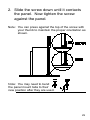
1
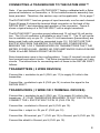
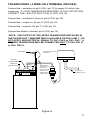
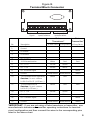
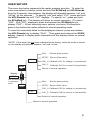
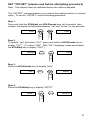
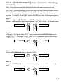
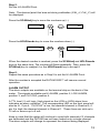
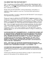
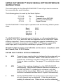
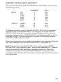
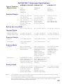
DATUM
™
00
20
Dual Channel Meter and Manometer
Operating Manual
1
Contents
INTRODUCTION ........................................................................................... 3
CONNECTING A TRANSDUCER TO THE DATUM 2000™ ........................ 4
TRANSMITTERS ( 2 WIRE DEVICES) ..................................................... 4
TRANSDUCERS ( 3 WIRE OR 3 TERMINAL DEVICES) ......................... 4
TRANSDUCERS ( 4 WIRE OR 4 TERMINAL DEVICES) ......................... 5
OPERATING NOTES .................................................................................... 7
OvEr AND UndEr MESSAGES ................................................................. 7
SAMPLING RATE ..................................................................................... 7
LOCKING ONTO A CHANNEL ................................................................. 7
DISPLAYING BOTH CHANNELS ............................................................. 7
MANOMETER ANALOG OUTPUT ........................................................... 7
RAPIDLY CHANGING INPUT SIGNAL .................................................... 7
TEST MODE ............................................................................................. 7
USER SETUPS ............................................................................................. 8
SET “OFFSET” .............................................................................................. 9
HI /LO ALARM SETPOINTS ....................................................................... 11
ALARM OUTPUT .................................................................................... 12
INSTALLATION OF PRESSURE FITTINGS FOR THE MANOMETER ..... 13
CALIBRATING THE DATUM 2000™. ......................................................... 14
CALIBRATING THE DATUM 2000™ USING KNOWN PRESSURES ... 14
CALIBRATING THE DATUM 2000™ USING AN EXTERNAL
REFERENCE VOLTAGE: ....................................................................... 15
CALIBRATING THE DATUM 2000™ FOR A TRANSDUCER
USING THE INTERNAL REFERENCE VOLTAGE ................................. 15
CALIBRATING THE DATUM 2000™ FOR A TRANSMITTER
USING THE INTERNAL REFERENCE VOLTAGE ................................. 16
CALIBRATING VOLTAGE INPUT AND CURRENT INPUT ........................ 18
ERASING CALIBRATION IN A CHANNEL ................................................. 21
SETRA DATUM 2000™ RS232 SERIAL OPTION INTERFACE
INSTRUCTIONS ..................................................................................... 23
DATUM 2000™ SERIAL OPTION COMMANDS .................................... 23
OUTPUT DATA FORMAT ....................................................................... 24
CHANGING THE BAUD RATE AND PARITY ........................................ 25
DATUM 2000™ MANOMETER SPECIFICATIONS .................................... 26
DATUM 2000™ METER AND MANOMETER SPECIFICATIONS ............. 27
PANEL MOUNT INSTRUCTIONS .............................................................. 28
"FCC WARNING" ........................................................................................ 30
RETURN INSTRUCTIONS ......................................................................... 31
LIMITED WARRANTY AND LIMITATION OF LIABILITY ........................... 31
2
DATUM
2000™
INTRODUCTION
Thank you for purchasing a Setra DATUM 2000™ meter or manometer.
Setra’s DATUM 2000™ is a compact dual channel meter with a 4 1/2 digit
LED display designed to mate with one or two transducers or transmitters
with a cable connection.
The DATUM 2000™ manometer is a single unit which combines a DATUM
2000™ meter with a Setra transducer. The Setra transducer is connected to
the Channel One inputs of the manometer, with Channel Two inputs available for external connection to another Setra transducer or transmitter.
The DATUM 2000™ meter and manometer are easy to use and install and
may be used on a benchtop or panel-mounted.
IMPORTANT
Please familiarize yourself with each set of instructions before attempting to
install your meter or manometer or perform a procedure. The meter has a
"time-out" safety feature to prevent miscalibration. Every time a new
message is displayed during a procedure, you have 30 seconds to respond.
If you don't respond within 30 seconds the meter will reset itself to normal
operation.
3
CONNECTING A TRANSDUCER TO THE DATUM 2000™
Note: If you purchased your DATUM 2000™ factory calibrated with a Setra
pressure transducer or transmitter, a 10 foot cable/connector assembly has
been provided. Therefore, this section may not be applicable. Go to page 7.
The DATUM 2000™ has two groups of input terminals, one for each channel.
Figure B (page 6) shows the terminal block connector on the back of the
DATUM 2000™ and describes each position of the connector. Figure A
shows a typical setup of a DATUM 2000™ with a single transducer.
The DATUM 2000™ provides ground referenced 12 volt and 24 volt excitation. The 24 volt excitation is available on pins 5 and 11. The 12 volt excitation is available only on pin 10. (If two 12 volt transducers [transmitters] are
being used, both units must be connected to pin 10.) DO NOT USE THE
EXCITATION FROM THE METER TO POWER ANY OTHER DEVICE
BESIDES THE 1 OR 2 TRANSDUCERS OR TRANSMITTERS THAT THE
METER IS DISPLAYING. UNDER NO CIRCUMSTANCES SHOULD MORE
THAN 60 mA BE DRAWN FROM THE DATUM.
Setra transducers come in two configurations: 3 wire (3 terminal) circuits and
four terminal equivalent circuits. The Setra transmitters are known as 2 wire
circuits. The instructions for connecting each of these to the DATUM 2000™
follows:
TRANSMITTERS ( 2 WIRE DEVICES)
Connect the + excitation to pin 5 (CH2: pin 11) to supply 24 volts to the
transmitter.
Connect the - excitation to pin 8 (CH2: pin 14) to return the signal to the
DATUM 2000™.
TRANSDUCERS ( 3 WIRE OR 3 TERMINAL DEVICES)
Connect the + excitation to pin 5 (CH2: pin 11) to supply 24 volts to the
transducer. IF YOUR TRANSDUCER REQUIRES 12 VOLT EXCITATION,
CONNECT THE + EXCITATION TO PIN 10 (CH2: PIN 10).
Connect the - excitation to Ground, pin 9 (CH2: pin 15).
Connect the + output to +IN, pin 6* (CH2: pin 12).
Connect the -IN terminal, pin 7* (CH2: pin 13) to Ground, pin 9 (CH2: pin 15).
Connect the shield to Ground, pin 9 (CH2: pin 15).
4
TRANSDUCERS ( 4 WIRE OR 4 TERMINAL DEVICES)
Connect the + excitation to pin 5 (CH2: pin 11) to supply 24 volts to the
transducer. IF YOUR TRANSDUCER REQUIRES 12 VOLT EXCITATION,
CONNECT THE + EXCITATION TO PIN 10 (CH2: PIN 10).
Connect the - excitation to Ground, pin 9 (CH2: pin 15).
Connect the + output to +IN, pin 6* (CH2: pin 12).
Connect the - output to -IN, pin 7* (CH2: pin 13).
Connect the shield to Ground, pin 9 (CH2: pin 15)
*NOTE: THE OUTPUT OF THE SETRA TRANSDUCER INSTALLED IN
THE DATUM 2000™ MANOMETER IS AVAILABLE ON PIN 6 AND 7. DO
NOT APPLY AN ELECTRICAL SIGNAL TO CH1: PIN 6 or CH1: PIN 7. A
SECOND TRANSDUCER MAY BE CONNECTED ONLY TO CH2: PIN 12
or CH2: PIN 13.
Setra pressure/vacuum
Transmitter
AC Adapter
Channel 1
Inputs/Excitations
Channel 2
Alarm
Signals
DANGER
REFERENCE
VOLTAGE
>
>
>
>
>
>
SEE CALIBRATION
INSTRUCTIONS BEFORE
USING REF. VOLTAGE
Inputs/Excitations
Supplied with
connector to join
the two foot
transducer cable
and the ten foot
digital pressure
readout cable
Pressure Line
(installed by user)
238652 REV B
Figure A
5
Figure B
Terminal Block Connector
1 2 3 4 5 6 7 8 9 10 111213 14 15
Alarm
Signals
Channel 1
Inputs/Excitations
Channel 2
Inputs/Excitations
Setra
Transducer*
Pin
Description
1
.
Ground
2
.
HiALArm
3
.
Lo ALArm
4
.
Ch.1/Ch.2
5
.
+24Voltsexcitation
White
Red
6
.
Ch.1+In
Yellow
Green
7
.
Ch.1-In
Brown
White
8
.
Ch.1Currentinput
9
.
Ground
10.
+12Voltsexcitation(optional)
Caution:Donot common
toPin5orPin11(+24Vexc.)
White
Red
11.
+24Voltsexcitation
Caution:Donot common
toPin10(+12Vexc.)
White
Red
12..
Ch.2 +In
Yellow
Green
13.
Ch.2 -In
Brown
White
14.
Ch.2Currentinput
15.
Ground
Setra
Transmitter*
w/RedCable w/GrayCable w/GrayCable
Red
Black
Black/Shield Black/Shield
Shield
Red
Black
Black/Shield Black/Shield
Shield
*IMPORTANT: If you are not using a Setra transducer or transmitter, see
manufacturer's transducer/transmitter operating instructions for terminal
circuit configuration and then connect the wires to the corresponding pins
listed in the above chart.
6
OPERATING NOTES
OvEr AND UndEr MESSAGES
In addition to displaying the numeric pressure reading, the DATUM 2000™
may also display "UndEr" and OvEr". If the pressure reading exceeds
+31999 (disregard decimal point), the display will not show the input pressure, instead it will display "OvEr". If the pressure reading is less than -9999
(disregard decimal point), the display will not show the input pressure,
instead it will display "UndEr".
SAMPLING RATE
The DATUM 2000™ will read the channel, 2 to 3 times a second. The speed
of the update is determined by the voltage of the channel being read. If the
meter has two channels calibrated, it will display each channel for 8 readings,
and then switch to the other channel. The exact time the meter will display a
channel is dependent on the voltage of that channel. Each channel will be
displayed for approximately 3 to 4 seconds.
LOCKING ONTO A CHANNEL
Press the HOLD/mode key to force the DATUM 2000™ to continuously
display the present channel. Upon power-up, the Datum 2000™ will display
both channels.
DISPLAYING BOTH CHANNELS
Press the SCAN/adj key to force the DATUM 2000™ to resume displaying
both channels.
MANOMETER ANALOG OUTPUT
The output of the Setra transducer installed in the DATUM 2000™ Manometer is available at the rear terminal strip on pins 6 and 7 and marked Channel 1 +IN, Channel 1 -IN
RAPIDLY CHANGING INPUT SIGNAL
For a signal whose magnitude is increasing very rapidly, the DATUM 2000™
can select the wrong integration time. This can cause a single reading
overflow of the A/D converter. This overflow can cause the sign of the
reading to be incorrectly set. Such an occurrence can cause an improper
setting of the alarms. This condition will self-correct once the input signal
has stabilized. This occurrence will rarely, if ever, be seen.
TEST MODE
There is a test mode in which the DATUM 2000™ will display the output of
the A/D converter reading of Channel 1 without performing the units conversion. This mode is accessible only by holding both the SCAN/adj and
HOLD/mode keys down when the power is applied to the DATUM 2000™.
If you accidentally enter this mode, you can exit by pressing either key.
7
USER SETUPS
The menu tree below represents the meter program structure. To enter the
menu and select a channel, press and hold the SCAN/adj and HOLD/mode
keys for 8 seconds, then release; the display will alternate between “cal” and
“noYes” for ten seconds.* To specify “yes” and select “CH1”, press and hold
the HOLD/mode key until “CH1” displays. To specify “no”, press and hold
the SCAN/adj key. The display will return to normal operation. (To select
“CH2”: With “CH1” displayed, press and release the SCAN/adj key to
display “CH2”.) When choosing menu options, you have 30 seconds to
press a key before the meter defaults to normal operating mode.
To view the commands listed for the displayed channel, press and release
the HOLD/mode key to display “ALAr” . Then press and release the SCAN/
adj key (repeat) to display each command until the display returns to normal
operation.
*NOTE: If the meter has not been calibrated at the factory, when the meter is turned
on, the display will alternate between “cal” and “noYes” .
ALAr
Set the alarm points.
OFF57 Set an offset value.
CH1
CAL_U Calibrate CH1 for voltage in (transducer).
CAL_C Calibrate CH1 for current in (transmitter).
SCAN
adj
Return to normal operation.
Display
cal
0.000
Cal is lit when
in calibration
mode.
HOLD
mode
ALAr
Set the alarm points.
OFF57 Set an offset value.
CAL_U Calibrate CH2 for voltage in (transducer).
CH2
CAL_C Calibrate CH2 for current in (transmitter).
Return to normal operation.
Return to normal operation.
8
SET “OFFSET” (please read before attempting procedure)
Note: The channel must be calibrated before the offset is adjusted.
The ”OFFSET” command allows you to adjust the reading relative to a known
value. To set the ”OFFSET” use the following procedure:
Step 1.
Press and hold the SCAN/adj and HOLD/mode keys for 8 seconds, then
release; the display will alternate between “cal” and “noYes” for ten seconds.
0.00
SCAN
adj
HOLD
mode
CAL
Step 2.
To specify “yes” and select “CH1”, press and hold the HOLD/mode key to
display “CH1” . (To select “CH2”: With “CH1” displayed, press and release
the SCAN/adj key to display “CH2”.)
noYES
SCAN
adj
HOLD
mode
CH1
Step 3.
Press the HOLD/mode key to display “ALAr”.
CH1
SCAN
adj
HOLD
mode
ALAr
Step 4.
Press the SCAN/adj key to display “OFFST”.
ALAr
SCAN
adj
HOLD
mode
OFF57
9
Step 5.
Press the HOLD/mode key to display the number “0”.
Note: The decimal point that was set during calibration (CAL_U, CAL_C) will
be displayed.
OFF57
SCAN
adj
HOLD
mode
0.
Step 6.
Set the value you wish the meter to display at the presently applied pressure.
Press the SCAN/adj key to move the numbers up (+).
0.
SCAN
adj
HOLD
mode
25.
Press the HOLD/mode key to move the numbers down (-).
0.
SCAN
adj
HOLD
mode
–25.
When the desired number is reached, press the SCAN/adj and HOLD/mode
keys at the same time. The number will flash repeatedly. Then, press the
SCAN/adj key to readjust the number or the HOLD/mode key to accept it.
After the number is accepted, the meter will display “bUSY” for 10 seconds
and then resume normal operation.
10
HI /LO ALARM SETPOINTS (please read before attempting
procedure)
Note: The channel must be calibrated before the alarm points are set.
The “ALAr” command allows you to set high and low pressure alarm points.
The HI ALARM or LO ALARM indicator light is lit if the applied pressure
exceeds the set values. The alarm output signals are available at the terminal strip. To set the Hi ALARM and Lo ALARM, use the following procedure:
Step 1.
Press and hold the SCAN/adj and HOLD/mode keys for 8 seconds, then
release; the display will alternate between “cal” and “noYes” for ten seconds.
0.00
SCAN
adj
HOLD
mode
CAL
Step 2.
To specify “yes” and select “CH1”, press and hold the HOLD/mode key to
display “CH1”. (To select “CH2”: With “CH1” displayed, press and release
the SCAN/adj key to display “CH2”.)
noYES
SCAN
adj
HOLD
mode
CH1
Step 3.
Press the HOLD/mode key to display “ALAr”.
CH1
SCAN
adj
HOLD
mode
ALAr
Step 4.
Press the HOLD/mode key to display the present value of the Low Alarm
point.
ALAr
SCAN
adj
HOLD
mode
0.
11
Step 5.
Set the LO ALARM Point.
Note: The decimal point that was set during calibration (CAL_U, CAL_C) will
be displayed.
Press the SCAN/adj key to move the numbers up (+).
0.
SCAN
adj
HOLD
mode
25.
Press the HOLD/mode key to move the numbers down (-).
0.
SCAN
adj
HOLD
mode
–25.
When the desired number is reached, press the SCAN/adj and HOLD/mode
keys at the same time. The number will flash repeatedly. Then, press the
SCAN/adj key to readjust it or the HOLD/mode key to accept it.
Step 6.
Repeat the same procedure as in Step 5 to set the HI ALARM Point.
After the number is accepted the DATUM 2000™ will resume normal
operation.
ALARM OUTPUT
The alarm outputs are available on the terminal strip on the back of the
meter. The signals available are HI ALARM, position 2, LOW ALARM,
position 3, and CH1/CH2, position 4.
A TTL level ( 5 volt logic ) high signal on the LOW or HIGH alarm lines
indicates an alarm condition. The corresponding LED on the front panel will
also be lit. If pin 4, “CH1/CH2” is low, the alarmed channel is Channel 2; if
pin 4 is high, the alarmed channel is Channel 1. These lines can sink up to
12 mA or source up to 8 mA.
Keep in mind that the meter will continue to scan both channels if 2 channels
are calibrated and the DATUM has not been locked onto a single channel.
The alarm outputs will change to represent the channel being displayed.
12
INSTALLATION OF PRESSURE FITTINGS FOR
THE MANOMETER
Your transducer is designed for most accurate operation when subjected to
pressures within the designated pressure range. Refer to catalog bulletin
specifications for proof pressure limits. Subjection to excessive pressure
voids the warranty. DO NOT OVERPRESSURE.
CAUTION: DO NOT SUBMERGE IN LIQUIDS, USE IN AMBIENT CONDITIONS CORROSIVE TO ANODIZED ALUMINUM, SUBJECT TO SPRAY
OR DRIPPING, OR USE IN A HIGH VIBRATION ENVIRONMENT. THE
TRANSDUCER IS VERY SLIGHTLY SENSITIVE TO ACCELERATION IN
THE PRESSURE FITTING AXIS (SEE APPLICABLE SPECIFICATIONS
BULLETIN FOR ACCELERATION RESPONSE SPECIFICATIONS).
Standard thread sealants such as Teflon pipe tape generally are satisfactory.
For the most sensitive pressure ranges, excessive high torquing of a metal
pressure fitting may cause slight zero shift which may be trimmed out using
the “OFFSET” adjustment. Use of a plastic fitting often shows no noticeable
zero shift. The torquing effect does not appreciably affect linearity or sensitivity. The wrench flat on the pressure port should be used when installing
the positive pressure fitting.
See page 26 for transducer specifications and media compatibility.
13
CALIBRATING THE DATUM 2000™.
Note: If on power up, the Datum 2000™ display alternates between "cal"
and "no Yes", it has not been calibrated at the factory. If the Datum 2000™
(Channel 1 or 2) displays numbers on power up, one or both channels have
been calibrated at the factory.
Always allow the DATUM 2000™ and the transducers, transmitters, or
reference voltage supplies to warm-up 10 minutes before performing a
calibration.
Whenever possible, it is best to calibrate the DATUM 2000™ at the temperature expected during operation.
There are 3 ways to calibrate the DATUM 2000™: Applying pressure to a
transducer or transmitter connected to the DATUM 2000™; applying voltage
to simulate the transducer, or current for a transmitter, directly to the DATUM
2000™; or using the DATUM 2000™’s internal reference voltage. The way
you should calibrate your meter depends on the equipment you have available. If you can apply very accurate and stable pressures, use this method.
If you have a precision voltage source, use it to simulate the transducer’s
output. If you have a precision current source, use it to simulate the
transmitter’s output. If you cannot calibrate your DATUM 2000™ with the
methods above, you can use the internal reference voltage to calibrate your
DATUM 2000™.
CAUTION (DATUM 2000™ MANOMETER ONLY): CALIBRATING CHANNEL ONE
OF THE DATUM 2000™ MANOMETER WITH A VOLTAGE INPUT WILL RESULT
IN DAMAGE TO THE DATUM AND WILL VOID THE WARRANTY. THE DATUM
2000™ MANOMETER HAS BEEN CALIBRATED AT THE FACTORY FOR THE
SETRA TRANSDUCER INSTALLED INSIDE. IF YOU WISH TO PERFORM A
CALIBRATION ON THE DATUM 2000™ MANOMETER, YOU MUST APPLY
KNOWN PRESSURE TO THE TRANSDUCER. NEVER APPLY A VOLTAGE
SIGNAL TO THE CHANNEL ONE INPUTS (PINS 6 AND 7) ON THE BACK OF
THE DATUM 2000™ MANOMETER.
NOTE: THE OUTPUT OF THE SETRA TRANSDUCER INSTALLED IN THE
DATUM 2000™ MANOMETER IS AVAILABLE AT THE REAR TERMINAL STRIP
ON PINS 6 AND 7 AND MARKED CHANNEL 1 +IN, CHANNEL 1 -IN.
CALIBRATING THE DATUM 2000™ USING KNOWN PRESSURES
To calibrate the DATUM 2000™ with known pressures, be sure the DATUM
2000™ and the transducer or transmitter is properly connected as described
on pages 4 - 6.
Following the calibration procedures starting on page 18, enter the known
pressure of the system for the calibration points.
14
CALIBRATING THE DATUM 2000™ USING AN EXTERNAL REFERENCE
VOLTAGE:
Connect the external reference to the meter to simulate the transducer or
transmitter using the connection instructions on pages 4 - 6. Then, follow
the calibration instructions on page 18. During calibration, short -IN to
Ground, pin 7 and pin 9 (CH2: pin 13 and pin 15). Be sure to set the minimum voltage of the calibrator to the same value as the minimum output
voltage of the transducer. Apply the voltage/current for the first pressure
point and enter the pressure reading desired. Now apply the voltage/current
for the second pressure point and enter the desired pressure reading.
CALIBRATING THE DATUM 2000™ FOR A TRANSDUCER USING THE
INTERNAL REFERENCE VOLTAGE
The DATUM 2000™ has a very stable internal reference voltage which can
be used for calibration if the above methods cannot be used.
For the first pressure point the +IN, -IN and ground should all be shorted
together, pin 6, pin 7, and pin 9 (CH2: pin 12, pin 13, and pin 15). Enter the
pressure that corresponds to zero volts input. Use the following formula to
calculate the pressure that corresponds to zero volts input (see examples).
SLOPE
=
Full scale pressure – offset pressure
—————————————————
Full scale voltage – offset voltage
OFFSET
=
Pressure ( @ voltage ) – (SLOPE x voltage)
PRESSURE
=
(SLOPE x VOLTAGE) + OFFSET
(DEFINITION OF OFFSET: Offset pressure and offset voltage refers to the minimum pressure
input and voltage output of the transducer, e.g., a 0-5 volt output, 600-1100 mbar transducer, the
offset voltage is 0 and the offset pressure is 600.)
For the second pressure point, the -IN and ground should be shorted, pin 7
and pin 9 (CH2: pin 13 and pin 15). The reference voltage (either contact of
the 2 pin blue connector located behind the terminal strip) should be connected to the +IN, pin 6 (CH2: pin 12). Enter the pressure that corresponds
to this input voltage according to the formula above; the value of the reference voltage is recorded on the serial number label on the bottom of the
DATUM 2000™.
1st example:
A 1000 PSI transducer has no offset voltage and an output of 5 volts at 1000
psi. The DATUM 2000™ has a reference voltage of 2.4995.
SLOPE
=
1000 – 0
————— = 200
5–0
OFFSET
=
0 – 200 x 0 = 0
15
PRESSURE (@ 0)
= 200 x 0 + 0 = 0
PRESSURE (@ REF)
= 200 x 2.4995 + 0 = 499.9
2nd example:
A 20 psi transducer has an offset of .1 volts and will have an output of 5.1
volts for a 20 PSI pressure. The DATUM 2000™ has a 2.4993 reference
voltage.
SLOPE
=
20 – 0
———— = 4
5.1 – .1
OFFSET
=
0 – 4 x .1 = –.4
PRESSURE (@0) =
4 x 0 – .4 = –.4
PRESSURE (@ REF)
=
4 x 2.4993 – .4 = 9.597
3rd example:
A bidirectional transducer has +/- 2.5 volt output for +/- 14.70 reading. The
DATUM 2000™ has a reference voltage of 2.5082 volts.
SLOPE
=
14.70 – (–14.70)
—————————— = 5.88
2.5 – (–2.5)
OFFSET
=
14.70 – 5.88 x 2.5 = 0
PRESSURE (@ 0) =
0 x 5.88 – 0 = 0
PRESSURE (@ REF) = 2.5082 x 5.88 – 0 = 14.75
CALIBRATING THE DATUM 2000™ FOR A TRANSMITTER USING THE
INTERNAL REFERENCE VOLTAGE
The DATUM 2000™ has a very stable internal reference voltage which can
be used for calibration with transmitters. Before proceeding you must locate
the label on the bottom of the DATUM 2000™ which indicates the reference
voltage and the value of the transmitter input impedance for the channel you
wish to calibrate.
16
For the first pressure point connect the "mA" to gound, pin 8 to pin 9 (CH2:
pin 14 to pin 15). Enter the pressure that corresponds to zero mA input
(since most transmitters are 4 to 20 mA, 0 mA will have a negative value).
Use the following formula (see example):
SLOPE
=
Full scale pressure – offset pressure
————————————————————
Full scale mA – offset mA
OFFSET
=
Pressure ( @ mA ) – (SLOPE x mA)
mA
=
REFERENCE VOLTAGE / INPUT IMPEDANCE
PRESSURE =
(SLOPE x mA) + OFFSET
(DEFINITION OF OFFSET: Offset pressure and offset current (mA) refers to the minimum
pressure input and current output of the transmitter, e.g., a 4-20 mA output, 0 - 50 psi transmitter, the offset current is 4 mA and the offset pressure is 0.)
For the second pressure point, connect the reference voltage (either contact
of the 2 pin blue connector located behind the terminal strip) to the "mA", pin
8 (CH2: pin 14). Enter the pressure that corresponds to this input current
according to the formula above; the value of the reference voltage and the
"mA" input impedance is recorded on the serial label on the bottom of the
DATUM 2000™.
Example:
A 1000 PSI transmitter outputs 4 mA at 0 PSI and 20 mA at 1000 psi. The
DATUM 2000™ has a reference voltage of 2.4995 and channel 1 input
impedance is 149.01 ohms.
SLOPE =
1000 – 0
————— = 62.5
20 – 4
OFFSET =
0 – 62.5 x 4 = -250
PRESSURE (@0) =
mA =
62.5 x 0 – 250 = –250
2.4995/149.01 = 16.774 mA (0.016774 Amps)
PRESSURE (@ REF)
= 62.5 x 16.774 – 250 = 798.4
17
CALIBRATING VOLTAGE INPUT AND CURRENT INPUT
(please read before attempting procedure)
CAL_U and CAL_C commands allow you to calibrate the DATUM 2000™ by
entering two data points. (Calculate the pressure for the 2 calibration points
before beginning this procedure.) The DATUM 2000™ will determine the
conversion factor and display the applied pressure in the desired engineering
units. The maximum read-out is +31999 to -9999.
If unit has been previously calibrated the calibration must be erased before
calibrating the meter. Following this procedure without erasing the previous
calibration will not reprogram the meter.
Note: If at anytime you with to abort the calibration procedure, simply
disconnect power to the unit and the old calibration data will still be intact.
CAUTION: CALIBRATING CHANNEL ONE OF THE DATUM 2000™ MANOMETER WITH A
VOLTAGE INPUT WILL RESULT IN DAMAGE TO THE DATUM AND WILL VOID THE
WARRANTY. THE DATUM 2000™ MANOMETER HAS BEEN CALIBRATED AT THE
FACTORY FOR THE SETRA TRANSDUCER INSTALLED INSIDE. IF YOU WISH TO
PERFORM A CALIBRATION ON THE DATUM 2000™ MANOMETER, YOU MUST APPLY
KNOWN PRESSURE TO THE TRANSDUCER. NEVER APPLY A VOLTAGE SIGNAL TO
THE CHANNEL ONE INPUTS (PINS 6 AND 7) ON THE BACK OF THE DATUM 2000™
MANOMETER.
*Before beginning set up wiring for first calibration point. If using the internal reference voltage,
+IN, -IN and ground should all be shorted together, pin 6, pin 7 and pin 9 (CH2: pin 12, pin 13
and pin 15).
Step 1.
Press and hold the SCAN/adj and HOLD/mode keys for 8 seconds, then
release; the display will alternate between “cal” and “noYes” for ten seconds.
0.00
SCAN
adj
HOLD
mode
CAL
Step 2.
To specify “yes” and select “CH1”, press and hold the HOLD/mode key to
display “CH1” . (To select “CH2”: With “CH1” displayed, press and release
the SCAN/adj key to display “CH2”.)
noYES
SCAN
adj
HOLD
mode
CH1
Step 3.
Press the HOLD/mode key to display “ALAr”.
CH1
SCAN
adj
HOLD
mode
ALAr
18
Step 4.
Press the SCAN/adj key to display “OFFST”.
ALAr
SCAN
adj
HOLD
mode
OFF57
Step 5.
To calibrate voltage in (transducer), press the SCAN/adj key to display
“CAL U”. (If calibrating for voltage input, proceed to Step 7, if not, proceed to
Step 6 to calibrate for current input.)
OFF57
SCAN
adj
HOLD
mode
CAL_U
Step 6.
To calibrate current in (transmitter), press the SCAN/adj key again to
display “CAL_C”, then proceed to Step 7.
CAL_U
SCAN
adj
HOLD
mode
CAL_C
Step 7.
Setting the Decimal Point.
Note: The decimal point location set in this step will always be used for all
displayed pressure readings on this channel. The maximum read-out is
+31999 to -9999.
Press the HOLD/mode key to display “SETdP”.
CAL_U
SCAN
adj
HOLD
mode
SE7dP.
Step 7a.
Press and hold the SCAN/adj key and the decimal point will move to the left,
release key at desired location. (While the key is pressed, the decimal will
continue moving, left to right.) Press and release the SCAN/adj key to move
the decimal point one place at a time.
SE7dP.
SCAN
adj
HOLD
mode
SE.7dP
19
Step 7b.
Press the HOLD/mode key to accept the decimal point and the meter will
display the decimal point with zeroes.
S.E7dP
SCAN
adj
HOLD
mode
0.000
Step 8.
Enter a calibration data point. (Enter a number between +31999 and -9999.)
Note: The pressure or voltage/current must be applied to the appropriate
channel before entering this data point.
Caution: Do not try to calibrate Channel One of the DATUM 2000™
Manometer with a voltage input, this will damage the unit and void the
warranty. Never apply a voltage signal to the Channel One inputs (see
page 14).
Press the SCAN/adj key to move the numbers up (+).
0.000
SCAN
adj
HOLD
mode
30.000
Press the HOLD/mode key to move the numbers down (-).
0.000
SCAN
adj
HOLD
mode
—0.100
When the desired number is reached, press the SCAN/adj and HOLD/mode
keys at the same time. The number will flash repeatedly. Then, press the
SCAN/adj key to readjust the number or the HOLD/mode key to accept it.
After the calibration data point has been accepted, the meter will display
“bUSY” for 10 seconds and then display zero. The second data point may
be entered.
**Set up wiring for second calibration point. The meter is programmed to
allow unlimited time for this wiring. It will not default to normal operating
mode. If using the internal reference voltage, the -IN and ground should be
shorted, pin 7 and pin 9 (CH2: pin 13 and 15). The reference voltage (either
contact of the 2 pin blue connector located behind the terminal strip) should
be connected to the +IN, pin 6 (CH2: pin 12).
20
Step 9.
Repeat the same procedure as in Step 8 to enter the second calibration data
point. (Enter a number between +31999 and -9999.)
After the second calibration data point has been accepted, the meter will
display “bUSY” for 10 seconds and then return to normal operating mode
and immediately begin reporting.
ERASING CALIBRATION IN A CHANNEL
(please read before attempting procedure)
A channel of the Datum 2000 can be permanently deactivated by calibrating
the channel and entering zero for both pressure points. If you wish to erase
the calibration of a channel, follow the procedure beginning with Step 1, on
page 18. In Step 5, Select "CAL U". In Step 7, 7a and 7b, set the decimal
point to the first position. In Steps 8 and 9, enter a value of 0. (It does not
matter what, if any, voltage or current signals are applied to the Datum 2000
when you use the Calibration Procedure to erase a channel, as long as they
do not exceed the Datum's input specifications.)
21
22
SETRA DATUM 2000™ RS232 SERIAL OPTION INTERFACE
INSTRUCTIONS
The serial option for the Setra DATUM 2000™ has a 9 pin d-sub connector
for connecting the serial interface.
The following pinout is used by the Serial Option:
12345
00000
0000
6789
Pin
2
3
5
Description
Transmit (from DATUM)
Receive (into DATUM)
Signal Ground
The DATUM 2000™ Serial option operates with the following default parameters:
Baud
2400
Parity
None
Start bits
1
Data bits
8
Stop bits
1
The DATUM 2000™ does not support hardware or software handshaking,
e.g. RTS, CTS, DTR, and DSR are not supported, nor is XON/XOFF handshaking supported. Some computer equipment expects handshaking; for
instance, it may be necessary to jumper RTS to CTS at your computer's
serial input port, it may also be necessary to jumper DTR to DSR.
Shielded cables must be used with this unit to ensure compliance with
the Class A, Part 15 FCC limits.
DATUM 2000™ SERIAL OPTION COMMANDS
A
41H
Transmit every reading that is displayed by the meter with an
alarm condition indicated. Note: If the DATUM 2000™ is
locked onto a channel, the other channel will not print even if
it is in an alarm condition. See page 11 for setting the alarm
points.
C
43H
Transmit the readings displayed on the DATUM 2000™
continuously. Note this will transmit the active channel(s); if
the DATUM 2000™ is locked onto a channel, only that
channel will be transmitted. Hint: use command 1 or 2 to
lock onto a channel and then use C to print it continuously.
1
31H
Set the DATUM 2000™ to channel one and lock the meter
so only channel one is displayed. It then transmits one
reading for channel one. Channel one must be calibrated.
23
2
32H
Set the DATUM 2000™ to channel two and lock the meter
so only channel two is displayed. It then transmits one
reading for channel two. Channel two must be calibrated.
S
53H
Force the DATUM 2000™ to scan all active channels. This
has no effect for a DATUM 2000™ with only one channel
calibrated.
V
56H
Verify communication with the DATUM 2000™ Serial Option.
The DATUM 2000™ will respond "SETRA DATUM 2000".
When command A or C is active, the alarm print or continuous print will
continue until interrupted by a new command. The command that interrupts
the printing will not be read; therefore, to start a new command while the
Serial Option is outputting continuous data, send the new command twice.
Allow 1 second between commands transmitted to the DATUM 2000™.
Hint: Transmit a V to the DATUM 2000™, if the verify message, "SETRA
DATUM 2000", is not received, wait 1 second, and retransmit a V. Transmit
a V each second until the verification message is received. When the
verification message is received, the DATUM 2000™ is ready for a new
command.
OUTPUT DATA FORMAT
The data is transmitted by the DATUM 2000™ Serial option in the following
format, followed by a carriage return and a line feed.
C:nnnnn,SS
C
the channel number: "1" or "2".
nnnnn
the number or message displayed on the
DATUM 2000™.
SS
Status: "OK", "HI" for high alarm and "LO"
for low alarm.
Examples of data:
1: 9.298,
2: 11.438,
2: 0.UEr,
1: Un.dEr,
1: -11.04,
OK
HI
HI
OK
LO
The decimal point is always transmitted in the position programmed for
display by the DATUM 2000™. For messages such as OVER and UNDER,
the decimal point will appear in the message as above.
If the DATUM 2000 is in calibration mode, the DATUM will output "CAL" once
and then wait for a new command.
24
CHANGING THE BAUD RATE AND PARITY
The baud rate and parity of the DATUM 2000™ Serial Option can be set to
the following values:
BAUD:
300
600
1200
2400
4800
9600
PARITY:
NONE
ODD
EVEN
COMMAND
3
6
1
2
4
9
ASCII
33H
36H
31H
32H
34H
39H
N
O
E
4EH
4FH
45H
To change the baud or parity, transmit a P, ASCII 50H, and the command
number or letter from the table above. For example, to set the DATUM
2000™ to 9600 baud and even parity, transmit P (always allow 1 second
between commands sent to DATUM 2000™) and then transmit 9, to set the
baud rate to 9600. Set your computer or terminal to 9600 baud and then
transmit P and E to set even parity.
When you change the communications parameters, they are stored internally
and will be recalled every time the DATUM 2000™ is powered up.
Hint: Transmit a V to the DATUM 2000, if the verify message "SETRA
DATUM 2000", is not received, wait 1 second, and retransmit a V. Transmit
a V each second until the verification message is received. When the
verification message is received, the DATUM 2000™ is ready for a new
command. Now transmit a P, wait at least 1 second and transmit the baud or
parity parameter.
25
DATUM 2000™ Manometer Specifications
Type of Pressure
Measurement
w/Models 204/204D w/Model 239
w/Model 270
Gage
Absolute
Vacuum
Differential
Differential
Gage
Gage
Absolute
Barometric
0 to 25, 50, 100, 250,
500,1000 psig
0 to 25, 50, 100, 250,
500, 1000 psia
0 to 25, 50, 100 psid
0 to 14.7 psiv
0 to ±10, ±25, ±50,
±100 psid
0to0.5,1.0,2.5,5,
15, 30 inch WC
0 to ±0.25, ±.5,
±1.0, ±2.5, ±7.5,
±15 inch WC
0 to 5, 10 psid
0 to ±2.5, ±5 psid
0 to 5, 10, 20, 50,
100 psig
0 to 10, 20, 50,
100 psia
600-1100millibar
800-1100millibar
Standard Ranges
System Accuracy (RSS)
±0.11% FS ± 2 digits
±0.14% FS ± 2 digits ±0.05% FS ± 2 digits
0.14 max. ± 4 digits
0.11 max. ± 4 digits
0.35 max. ± 4 digits
0.35 max. ± 4 digits
0.07 max. ± 4 digits
0.04 max. ± 4 digits
Positive
1/4"-18 NPT internal
1/8"-27NPT internal
1/8"-27NPT internal
Reference
1/8"-27 NPT internal
(204D only)
1/8"-27NPT internal
N/A
Positive
Gas or liquid compatible with 17-4 PH
stainlesssteel.
Gases compatible
withstainlesssteel,
hard anodized 6061
aluminum,
Buna N O-ring.
(Stainlesssteelin
place of aluminum
onspecialorder.)
Dry or wet air, water
or other media
compatible with
aluminum, alumina
ceramics, gold
and elastomer
sealant.
Reference
Clean dry air or other
gases. (Non-corrosive,
non-condensable.)
Maximum line pressure
1000 psig (204D only)
Clean dry air or other N/A
gases. (Non-corrosive,
non-condensable.)
Maximum line pressure
250 psig
Normally 0 to 5 VDC for
unidirectionalpressure
or vacuum ranges.
0 to ±2.5 VDC for
bidirectionalranges.
Normally 0 to 5 VDC
forunidirectional
pressure.
0 to ±2.5 VDC for
bidirectionalranges.
Thermal Effects
%FS 60O-95OF
Thermal Zero Shift
Thermal Span Shift
Pressure Fittings
Pressure Media
Analog Output
Notes:
0 to 5 VDC for gage
and absolute ranges.
(1) Differential pressure models can be used to measure gage pressure by leaving
the reference port open to atmosphere.
(2) Line pressure refers to pressure applied to both high and low sides of the sensing
device simultaneously. Refer to the product data sheet to determine maximum
differentialpressureandoverpressurelimits.
26
DATUM 2000™ Meter and Manometer Specifications
Display
Type
Color
HeightofDigits
Maximum Readout
Reading Rate
Overload Signal (over range reading)
Underload Signal (under range reading)
PolaritySign
Brightness
Description
Light emitting diode
Red
0.56 inch
- 9999 to + 31999
2 to 3 times per second depending on
input voltage
OVEr
UndEr
Negative only
Constant
Physical
Operating Temperature
Storage Temperature
Width
Height
Meter
Manometer
Depth (incl. connector)
32° to 130°F (0° to 55°C)
-40° to 185°F (-40° to 85°C)
3.59 inches (91 mm)
1.74 inches (44 mm)
3.50 (89mm)
7 inches (178 mm)
(Allow at least 1/2" more for wires attached
toterminalstrip)
Cutout Dimensions
Meter
Manometer
Front Panel
Meter
Manometer
1/8 DIN: 1.77 in. x 3.62 in. (45 x 92 mm)
1/4 DIN: 3.54 in. x 3.62 in. (90 x 92 mm)
3.85 in. x 1.99 in. (98 x 50 mm)
3.85 in. x 3.74 in. (98 x 95 mm)
Electrical Data
Power
Domestic
European
Power Cord Length
(Domestic and European)
24 VDC (115 VAC 60 Hz 12 watt adapter
provided w/-1 models)
24 VDC (220 VAC 50 Hz 14 watt adapter
provided w/-2 models)
Adaptor has European 2 prong plug
withturret
6feet(approx.)
Accuracy (Readout Only)
At 73°F (23°C)
At 60° to 95°F (16° to 35°C)
± 0.01%R ± 1 digit
± 0.04%R ± 1 digit
Analog Output
Transducers
Transmitters
Same as transducer output voltage
No analog output; the DATUM 2000™
terminates the current loop
Adjustment Capabilities (accessible through the user set-up menus)
Voltage Inputs
Current Inputs
Maximum Reading
Minimum Reading
+11 to -11 volts
0 to 20 mA
+ 31999
- 9999
Input Specifications
Transmitterinputsignal
Transmitter input impedance
Transmitter input voltage drop
Transducer input signal
Transducer input impedance
4 - 20 mA
150 ohm
3 VDC (max.)
+11 VDC to -11 VDC
45K ohm
27
PANEL MOUNT INSTRUCTIONS
1. Slide the panel mount tab with screw
into slot on the side of the meter as
shown.
28
2. Slide the screw down until it contacts
the panel. Now tighten the screw
against the panel.
Note: You can press against the top of the screw with
your thumb to maintain the proper orientation as
shown.
Note: You may need to bend
the panel mount tabs to their
new position after they are used.
29
"FCC WARNING"
Warning: Changes or modifications to this unit not expressly approved by
the party responsible for compliance could void the user's authority to
operate the equipment.
NOTE: This equipment has been tested and found to comply with the limits
for a Class A digital device, pursuant to Part 15 of the FCC Rules. These
limits are designed to provide reasonable protection against harmful interference when the equipment is operated in a commercial environment. This
equipment generates, uses, and can radiate radio frequency energy and, if
not installed and used in accordance with the instruction manual, may cause
harmful interference to radio communications. Operation of this equipment in
a residential area is likely to cause harmful interference in which case the
user will be required to correct the interference at his own expense.
Shielded cables must be used with this unit to ensure compliance with
the Class A, Part 15 FCC limits.
30
RETURN INSTRUCTIONS
Please contact Setra (800-257-3872 or 978-263-1400) before returning unit for repair
to review information relative to your application. When returning a product to Setra,
the material should be carefully packaged and shipped prepaid to:
Setra Systems, Inc.
159 Swanson Road
Boxborough, MA 01719Dat
Attn: Repair Department
To assure prompt handling, please supply the following information and include it
inside the package of returned material:
1.
2.
3.
4.
Notes:
Name and phone number of person to contact.
Shipping and billing instructions
Full description of the malfunction.
Identify any hazardous material used with product.
Please remove any pressure fittings and plumbing that you have installed
and enclose any required mating electrical connectors and wiring diagrams .
Allow approximately 3 weeks after receipt at Setra for the repair and return of the unit.
Non-warranty repairs will not be made without customer approval and a purchase
order to cover repair charges.
LIMITED WARRANTY AND LIMITATION OF LIABILITY
SETRA warrants its products to be free from defects in materials and workmanship, subject to the
following terms and conditions: Without charge, SETRA will repair or replace products found to be
defective in materials or workmanship within the warranty period; provided that:
a)
the product has not been subjected to abuse, neglect, accident, incorrect wiring not our own,
improper installation or servicing, or use in violation of instructions furnished by SETRA;
b)
the product has not been repaired or altered by anyone except SETRA or its authorized
service agencies;
c)
the serial number or date code has not been removed, defaced, or otherwise changed; and
d)
examination discloses, in the judgment of SETRA, the defect in materials or workmanship
developed under normal installation, use and service;
e)
SETRA is notified in advance of and the product is returned to SETRA transportation prepaid.
Unless otherwise specified in a manual or warranty card, or agreed to in a writing signed by a SETRA
officer, SETRA pressure and acceleration products shall be warranted for one year from date of sale.
The foregoing warranty is in lieu of all warranties, express, implied or statutory, including but not
limited to, any implied warranty of merchantability for a particular purpose.
SETRA’s liability for breach of warranty is limited to repair or replacement, or if the goods cannot be
repaired or replaced, to a refund of the purchase price. SETRA’s liability for all other breaches is
limited to a refund of the purchase price. In no instance shall SETRA be liable for incidental or
consequential damages arising from a breach of warranty, or from the use or installation of its
products.
No representative or person is authorized to give any warranty other than as set out above or to
assume for SETRA any other liability in connection with the sale of its products.
159 Swanson Road, Boxborough, MA 01719-1304;
800-257-3872; (978) 263-1400; Fax. 978-264-0292;
WEB; www.setra.com; E-mail: [email protected]
SSO575 RevF 02/02/98
31