1
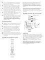
Temperature readings should be taken at the normal flow
rate after allowing the system to stabilise. The sensing
part of the thermometer probe must be fully submerged
in the water that is to be tested.
Before installation, the hot and cold water supply
systems must be thoroughly flushed to remove any dirt/
debris that may have accumulated. Failure to do so may
adversely affect the performance of themixing valve.
Any TMV that has been adjusted or serviced must be
re-commissioned and re-tested in accordance with the
manufacturer’s instructions.
Conditions of normal Use
TX402 When used as a TMV2 (TYPE 2) Valve
IMPORTANT INTRODUCTION NOTES
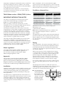
Operating Range
BS EN 1111
High Pressure
BS EN 1287
Low Pressure
Maximum Static Pressure
10 Bar*
10 Bar*
Hot & Cold Flow Pressure
1.0 to 5 Bar*
0.1 to 1 Bar
The valves covered by these instructions have been
tested and certified as being in compliance with
BS EN 1111:1999 and BS EN 1287:1999.
Hot Supply Temperature
55 to 65°C
55 to 65°C
Cold Supply Temperature
≤ 25°C
≤ 25°C
Valves operating outside the requirements of these
standards are not covered by the TMV2 Scheme and are
not guaranteed to operate as Type 2 valves.
Mixed Water Temperature
Maximum 46°C
Maximum 46°C
The installer should be aware of his duty of care and
responsibility in ensuring that compliance with regulations
is maintained. The valve is not guaranteed to function
correctly to the TMV2 specification unless it is installed
and used in accordance with these instructions. Regular
servicing is essential to ensure continued safe operation
of this thermostatic mixing valve. The recommended
service interval is no greater than 12 months.
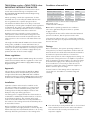
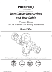
This Pegler Yorkshire Model TX402 in-line thermostatic
mixing valve, available in 15mm and 22mm sizes, is
intended to be fitted into applications where the reliable
control of hot water temperature is necessary to prevent
scalding. In the event of cold water supply failure, the
product will shut off the hot water supply.
Water regulations
The Pegler Yorkshire Model TX402 mixing valve must
be installed in accordance with the regulations of
the local water company and the Water Supply
(Water Fittings) Regulations 1999.
Approvals
This product is certified under the BuildCert TMV2
scheme and has been independently tested by an
approved testing laboratory WRc-NSF and is a Water
Regulations Advisory Scheme (WRAS) approved product
and listed in the Water Fittings and Materials Directory.
Installation
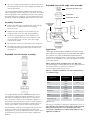
Separate isolation valves must be installed on the hot and
cold water inlet supplies. To ensure proper performance
of the thermostatic mixing valve, the isolating valves
should preferably be full bore and always be fully open
during operation.
The mixing valve is supplied with filter elements but it is
advisable to additionally install Y-strainers on the hot and
cold water supplies. The isolating valves and strainers
should be installed as close as practicable to the location
of the mixing valve and should always be in an accessible
location.
Minimum hot inlet to mixed outlet temperature
differential =10°C
*3 bar with PEX + PB Pipe
Note: Valves operating outside these conditions can
not be guaranteed by the Scheme to operate as
Type 2 valves.
The highest flow rates will be achieved under balanced
pressure conditions, but the pressure at the valve inlets
must be within a ratio of 5:1 under flow conditions and
the size and layout of pipework and fittings must take this
into account.
Fitting
Before installation, the system operating conditions of
inlet pressures, hot and cold inlet temperature and hot
and cold water flow rates should be determined and
confirmed to be within the expected conditions of normal
use shown in Table 4.
Valves must operate in either a high pressure setting
or a low pressure setting. These valves are not capable
of operation with, for instance hot water supply in one
pressure range and cold water supply in the other
pressure range. In these conditions it is necessary to
either boost one pressure or reduce the other so that
both supplies are within a common pressure range.
If your water supply cannot meet these conditions then
the valve cannot be guaranteed to operate as a Type 2
valve.
Operating pressures above 5.0 Bar will require the
installation of a pressure reducing valve. Correct location
of the mixing valve is important to ensure that it is
accessible for commissioning and servicing.
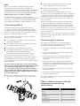
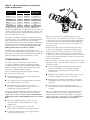
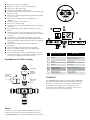
nThe valve body is
clearly marked with
‘C’ for Cold and a
blue indicator and
‘H’ for Hot and a red
indicator. The valve
must be correctly
connected to the
espective supplies.