1
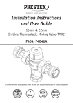
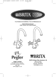
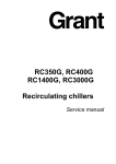
Installation Instructions and User Guide
Installation
Instructions
15mm & 22MM
In-Line Thermostatic Mixing Valve-TMV2
and User Guide
15mm & 22mm
In-Line Thermostatic
Mixing Valve-TMV3
Model P404
P402, P402UA
It is important that these guidance notes are read and fully understood prior to product installation
2
Year
BS
7942
NHS
D08
IMPORTANT INTRODUCTION NOTES
The valves covered by these instructions
have been tested and certified as being in
compliance with BS 7942:2000 and NHS
Estates Model Engineering Specification D 08.
Valves operating outside the requirements of
these standards are not covered by the TMV3
Scheme and are not guaranteed to operate as
Type 3 valves.
The installer should be aware of his duty
of care and responsibility in ensuring that
compliance with regulations is maintained.
The valve is not guaranteed to function
correctly to the TMV3 specification unless it
is installed and used in accordance with these
instructions.
Regular servicing is essential to ensure
continued safe operation of this thermostatic
mixing valve. The recommended service
interval must be based on the valve response
to the in-service cold water failure test results
(see page 6)
The installer should be aware of his duty of care and responsibility in ensuring that comp
with regulations is maintained. The valve is not guaranteed to function correctly to the T
specification unless it is installed and used in accordance with these instructions.
Regular servicing is essential to ensure continued safe operation of this thermostatic mix
valve. The recommended service interval must be based on the valve response to the incold water failure test results (see page 6)
Installation
This Pegler Yorkshire
Model P402
in-line must
thermostatic
valve, available in 15mm an
Separate
isolation
valves
be mixing
installed
sizes, is intended to be fitted into applications where the reliable control of hot water
on
the hot
and cold
water
inlet
temperature
is necessary
to prevent
scalding.
In thesupplies.
event of cold To
water supply failure, th
product willproper
shut off the
hot water supply. of the thermostatic
ensure
performance
mixing valve, the isolating valves should
Water regulations
preferably be full bore and always be fully
The Pegler
Yorkshireoperation.
Model P402 mixing valve must be installed in accordance with the
open
during
regulations of the local water company and the Water Supply (Water Fittings) Regulation
The mixing valve is supplied with filter
Approvals
elements but it is advisable to additionally
install Y-strainers on the hot and cold water
This product is certified under the BuildCert TMV3 scheme and has been independently t
supplies.
isolating
valves
the recognisedThe
test laboratory
WRc-NSF
and is aand
Waterstrainers
Regulations Advisory Scheme (W
approved product
and listed in as
the Water
and Materials Directory.
should
be installed
closeFittings
as practicable
to
the
location
of
the
mixing
valve
and
should
Installation
always be in an accessible location.
Separate isolation valves must be installed on the hot and cold water inlet supplies. To en
proper performance of the thermostatic mixing valve, the isolating valves should preferab
Before
installation,
the
hotoperation.
and cold water
full bore and
always be fully open
during
The mixingsystems
valve is supplied
with be
filterthoroughly
elements but it is advisable
supply
must
flushedto additionally install
Y-strainers on the hot and cold water supplies. The isolating valves and strainers should
to
remove
any
dirt/debris
that
may
have
installed as close as practicable to the location of the mixing valve and should always be
accumulated.
accessible location. Failure to do so may adversely
affect the performance of the mixing valve.
Before installation, the hot and cold water supply systems must be thoroughly flushed to
any dirt/debris that may have accumulated. Failure to do so may adversely affect the
performance of the mixing valve.
CONDITIONS OF NORMAL USE
CONDITIONS OF NORMAL USE
Table 1
Table 1
This Prestex Model P402 in-line thermostatic
mixing valve, available in 15mm and 22mm
sizes, is intended to be fitted into applications
where the reliable control of hot water
temperature is necessary to prevent scalding.
In the event of cold water supply failure, the
product will shut off the hot water supply.
Water Regulations
The Prestex Model P402 mixing valve must be
installed in accordance with the regulations of
the local water company and the Water Supply
(Water Fittings) Regulations 1999.
Approvals
This product is certified under the BuildCert
TMV3 scheme and has been independently
tested by the recognised test laboratory
WRc-NSF and is a Water Regulations Advisory
Scheme (WRAS) approved product and listed in
the Water Fittings and Materials Directory.
Operating Range
Maximum static pressure - bar
Hot & cold flow pressure - bar
Hot supply temperature - °C
Cold supply temperature - °C
High Pressure
10
1.0 to 5
52 to 65
5 to 20
Low Pressure
10
0.2 to 1
52 to 65
5 to 20
Minimum hot inlet to mixed outlet temperature
differential = 10oC
Note: Valves operating outside these
conditions can not be guaranteed by the
Scheme to operate as Type 3 valves.
The highest flow rates will be achieved under
balanced pressure conditions, but the pressure
at the valve inlets must be within a ratio of
5:1 under flow conditions and the size and
layout of pipework and fittings must take this
into account.
FITTING
Assembly Procedure
Before installation, the system operating
conditions of inlet pressures, hot water
temperature and hot and cold water flow rates
should be determined and confirmed to be
within the expected conditions of normal use.
• Unpack the main valve assembly, remove the three plastic protection caps and check that the bores are free of debris and the end
sealing faces are clean.
Valves must operate in either a high pressure
setting or a low pressure setting. Valves are
not capable of operation with, for instance hot
water supply in one pressure range and cold
water supply in the other pressure range. In
these conditions it is necessary to either boost
one pressure or reduce the other so that both
supplies are within a common pressure range.
Correct location of the mixing valve is
important to ensure that it is accessible for
commissioning and servicing.
• The valve body is clearly marked with ‘C’ for Cold and a blue indicator and ‘H’ for Hot and a red indicator.
The valve must be correctly connected to the respective supplies
• The use of sealing compounds must be avoided since they may intrude into
the water supply and impair the valve performance.
The Prestex Model P402 thermostatic mixing
valve is supplied with the tail pieces, inlet
filter screen and main body gasket seals
separately located in the packing box.
Each tail piece comprises: a housing with
union nut and an internally fitted, WRAS
approved non return value.
• Unpack the two tailpieces and confirm they are complete with union nuts and compression nuts and olives.
• Locate the sealing gaskets, insert them into the union nuts against the faces of the
tailpieces and screw the union nuts onto the valve until a tight seal has been made.
• Remove the compression nuts and olives from the tailpieces. Locate the inlet filter
screens and insert them into the bore of the tailpieces up to the shoulder.
• Assemble the valve to the pipework and ensure the hot and cold water pipes have full penetration into the tailpiece.
• Tighten the compression nuts ensuring that the end of the pipe remains in contact with
the filter element.
Exploded
tailpiece
Exploded
viewview
of tailof
pipe
assembly assembly
The Prestex Model P402UA mixing valve is
The Pegler Model Yorkshire P402UA mixing valve is optionally provided with an
optionally
provided with
assemblies
in
lieu of the
tailpiece arrangement
shownangled
above. This
allows the connections
of
water supplies
be parallel
to thearrangement
mixed water outlet
for ease
of piping layou
lieu oftothe
tailpiece
shown
above.
valve assemblies incorporate non-return valves, filters, isolation valves and tes
This allows the connections of the hot and
cold water supplies to be parallel to the mixed
water outlet for ease of piping layouts. The
The assemblies comprise an integral full bore ball valve and in-line strainer in
angled
valve isassemblies
incorporate
non-return
When this
arrangement
used, the requirements
for isolation
valves and Y-st
mentioned
are regarded
fulfilled. valves and test points.
valves,
filters,asisolation
Exploded view of angled valve assembly
The assemblies comprise an integral full bore
ball valve and in-line strainer in an angled
housing. When this arrangement is used,
the requirements for isolation valves and
Y-strainers previously mentioned are regarded
as fulfilled.
Exploded view of angled valve assembly
PRESSURE TAKE-OFF POINT PLUG
SEAL
HEADWORK
SEAL
FILTER MESH
UNION NUT
UNION
SEAL
ISOLATION
VALVE
HANDLE
ISOLATION VALVE
APPLICATION
The Prestex Model P402 thermostatic mixing
valve has been independently tested by
WRc-NSF against the requirements of BS
7942:2000 and NHS D08 and certified as
complying with the requirements of the
TMV3 Scheme and is suitable for use in the
designations shown in the table below.
Valves approved for designation for use ‘HP’
only:- If a water supply is fed by gravity then
the supply pressure should be verified to
ensure the conditions of use are appropriate
for the valve.
The range of available temperature adjustment
is 35°C to 48°C BUT the mixed water
temperature at the terminal fitting must
never exceed the temperature value for the
particular application (i.e. the maximum
mixed water temperature may be 2°C above
the recommended maximum set outlet
temperatures).
Note:
46°C is the maximum recommended mixed
water temperature from the bath tap. The
maximum temperature takes account of the
allowable temperature tolerances inherent in
thermostatic mixing valves and temperature
losses in metal baths
46°C is not a safe bathing temperature for
adults or children.
The British Burns Association recommends
37°C to 37.5°C as a comfortable bathing
temperature for children. In premises covered
by the Care Standards Act 2000, the maximum
mixed water outlet temperature is 43°C.
COMMISSIONING
The valve must be commissioned under normal
site system conditions and after establishing
supply conditions with the hot and cold water
supplies open, leave the system running to
allow temperatures and pressures to stabilise
and be checked.
Prior to commencing commissioning, the
following checks should be carried out.
• The designation of the thermostatic mixing valve matches the application.
The supply pressures and temperatures are Table 2 – Required maximum set outlet temperatures at•commissioning.
within the operating range of the valve.
Application
Designation
Maximum Set Mixed
• Isolating valves and strainers are provided.
Water Temperature
• The supply temperatures are within the Bidet
HP-B
38°C
range permitted for the valve and by LP-B
guidance information on the prevention of Shower
HP-S
41°C
legionella etc.
LP-S
Table 2 - Required maximum set outlet
temperatures at commissioning.
Washbasin
Bath*
Bath*
(assisted)
*22mm
*22mm only
only
HP-W
LP-W
HP-T44
LP-T44
HP-T46
LP-T46
41°C
44°C
46°C
If all these conditions are met, proceed to set
the temperature as described below.
The Prestex thermostatic mixing valve is
supplied factory set at 43°C but the valve may
be simply adjusted after installation.
When the valve has been installed with the correct conditions of use it is advised that th
subjected to exercise prior to the commissioning at the application temperature. Operat
from full cold to full hot at least three times.
1. Record the temperature of the hot The mixed water temperature at the
With the the
valve at the full cold
bringwater
the valve
to the correct application tempera
position
and cold
supplies.
terminal fitting must never exceed
turning the spanner clockwise.
the valve
this temperature,
the valv
2.IfRecord
theovershoots
temperature
of the mixedreturn
maximum temperature setting
for the
cold condition, and reset it to the correct temperature +0-2°C. Do not set a valve on a
provide
water
at the operation.
largest draw-off flow rate.
particular application. Note,temperature
It is not as this will not
consistent
3. Record the temperature of the mixed possible to install one thermostatic mixing
the valve is set to the
for the application
carry out 5 cold w
required
watertemperature
flow at a smaller
draw-off flow
valve to supply two differingWhen
applications
isolation
tests
to further exercise
the valve.
rate,
which shall be measured.
unless the temperature of the
higher
setting
4. Isolate the cold water supply to the is limited to that of the lower application.
Commissioning Test sequence
of the
mixing
monitor the
mixed
After adjust the temperature
mixedvalve
waterand
in accordance
with
the valve applicatio
out water
temperature
recording the • Remove the plastic protective
cap
on top
of the
carry
( see
Table
2) and
the following
sequence:
1. Record the
of the
hot and cold
water supplies.
temperature
maximum
temperature
achieved
and the
the valve with an allen key.
2. Record the temperature of the mixed water at the largest draw-off flow
final stabilised temperature.
3. Record the temperature of the mixed water flow at a smaller draw-off f
shall
5. Record
the equipment, thermometer etc. • using a close fitting
rate, which
be measured.
used for
thetomeasurements.
spanner, reduce
the thecold water
4. Isolate
supply
the mixing valve and monitor the mixed
the maximum
temperature
achieved and t
Note: Therecording
final stabilised
temperature
should
mixed outlet water temperature
temperature.
temperature byfinal stabilised
not exceed
the values in Table 3
5. Record the equipment, thermometer etc. used for the measurements.
turning
clockwise.
Note: The final stabilised temperature should not exceed the values in Table3
Table 3 - Maximum mixed water • increase the mixed
temperatures
Table 3 Maximum mixed water temperatures
water outlet
temperature by
Application
Mixed water temperature °C
turning
Bidet
40
counterclockwise.
Shower
43
Washbasin
43
Bath (44°C fill)
46
When the valve has been installed with the
Bath (46°C fill)
48
correct conditions of use it is advised that
the valve is subjected to exercise prior to the
In Service
Testing
In Service Testing
commissioning at the application
temperature.
Operate the valve from full cold to full hot at
The purpose of in-service testing is to regularly monitor and record the performance of
The purpose of in-service testing is to regularly
least three times.
thermostatic mixing valve. Deterioration in performance can indicate the need for servic
and record the performance of the
work on the valve and/or monitor
water supplies.
thermostatic mixing valve. Deterioration in
With the valve at the full cold position
out the test sequence
detailed above
the same
or equivalent
equipment use
performance
canusing
indicate
the need
for service
bring the valve to the correct Carry
application
commissioning the valve.
work on the valve and/or water supplies.
temperature by turning the spanner clockwise.
If the valve overshoots this temperature,
Carry out the test sequence detailed above
return the valve to the full cold condition, and
using the same or equivalent equipment used
reset it to the correct temperature +0-2°C. Do
for commissioning the valve.
not set a valve on a lowered temperature as
this will not provide consistent operation.
If the mixed water temperature has changed
significantly from the previous test results
When the valve is set to the required
(e.g.>1K), record the change and before
temperature for the application carry out 5
re-adjusting the mixed water temperature carry
cold water isolation tests to further exercise
out the following checks;
the valve.
• All in-line or integral strainers are clean
• Any in-line or integral non-return valves or Commissioning Test sequence
other anti-backsiphonage devices are in
After adjusting the temperature of the mixed
good working order.
water in accordance with the valve application
• Any isolation valves are fully open.
(see Table 2) carry out the following sequence:
With an acceptable mixed water temperature
complete the test sequence detailed above.
If the final mixed water temperature is
greater than the values in Table 3 and/
or the maximum temperature exceeds the
corresponding value from the previous test
results by more then about 2K the need for
service work is indicated.
In-service tests should be carried out with a
frequency which identifies a need for service
work before an unsafe water temperature can
result.
Frequency of in-service testing
6 to 8 weeks after commissioning carry out
the test sequence detailed above 12 to 15
weeks after commissioning carry out the
test sequence detailed above. Depending on
the results obtained, the following course of
actions must be followed:
• If no significant changes (e.g.<1 K) in
mixed water temperature are recorded between commissioning and testing at 6 to 8 weeks, or between commissioning and testing at 12 to 15 weeks, the next in-
service test can be deferred to 24 to 28 weeks after commissioning.
• If small changes (e.g.1 to 2 K) in mixed water temperature are recorded in only one
of these periods, necessitating adjustment of the mixed water temperature, then the
next in-service test can be deferred to 24 to 28 weeks after commissioning.
• If small changes (e.g.1 to 2 K) in mixed water temperature are recorded in both of
these periods, necessitating adjustment of the mixed water temperature, then the
next in-service test should be carried out at 18 to 21 weeks after commissioning.
• If significant changes (e.g. >2 K) in mixed water temperature are recorded in both of
these periods, necessitating service work, then the next in-service test should be
carried out at 18 to 21 weeks after commissioning.
The general principle to be observed after the
first 2 or 3 in-service test is that the intervals
of future tests should be set to those which
previous tests have shown can be achieved
with no more than a small change in mixed
water temperature.
Note:
If there is a residual flow during the
commissioning or bi-annual verification (cold
water supply isolation test) then this is
acceptable providing the temperature of the
water seeping from the valve is no more
than 2°C above the designated maximum
mixed water outlet temperature setting of the
valve.
Temperature readings should be taken at the
normal flow rate after allowing the system to
stabilise. The sensing part of the thermometer
probe must be fully submerged in the water
that is to be tested. Any TMV that has been
adjusted or serviced must be re-commissioned
and re-tested in accordance with the
manufacturer’s instructions.
In the absence of any other instruction or
guidance, it is recommended that In-Service
Tests are carried out once every 6 months as a
minimum.
TMV Cleaning and Servicing Instructions
Most domestic water supplies contain calcium
which will separate out when the water is
heated in a system. The degree and speed of
scaling may vary depending on factors such as
water flow rates, system design, the hardness
of the water and the temperature to which the
water is heated.
Deposits of scale may over time form in
the valve, particularly at the hot inlet. The
formation of the scale may adversely affect
the performance of the valve which will be
detected during the in-service testing. If this
occurs it will be necessary to remove the valve
for de-scaling and servicing.
TO SERVICE THE VALVE:
SPARES
30.0°
• Isolate the hot and cold supply.
• Remove the valve to a clean working area.
In order to ensure that the Prestex Model P402
• Remove the protective cap.
thermostatic mixing valve continues to provide
• UnscrewInstructions
the headwork of the valve.
satisfactory service, only GENUINE Pegler spare
ng and Servicing
• Carefully remove the element and valve parts must be used.
ic water supplies
contain
will separate out when the water is
assembly
andcalcium
put towhich
one side.
ystem. The
degree and
scaling
may
varyguide
depending
• Remove
thespeed
main ofspring
and
flow
and on factors such as
tes, system
design, the
the water and the temperature to which the
carefully
puthardness
to one of
side.
2
ed.
• Inspect the components for contamination cale may over time form in the valve, particularly at the hot inlet. The formation
or damage.
may adversely affect the performance of the valve which will be detected during
or replace
asnecessary
necessaryto remove the valve for de-scaling1
e testing. •
If Clean
this occurs
it will be
•
Remove
the
two
o
rings
.
• Clean the valve body and headwork using a te the hot and
cold supply.
propriety
de-scaler
3
ove the valve
to a clean rinse
working
• Thoroughly
thearea.
body and headwork in ove the protective
cap.
clean water.
rew the headwork of the valve.
• Carefully fit new o rings from the service kit 4
5
fully remove the element and valve assembly and put to one side.
taking care to ensure they are not
ove the main spring and flow guide and carefully put to one side.
damagedforand
are correctly
7
ect the components
contamination
or located.
damage.
• Lubricate
the o rings with the lubricant n or replace
as necessary
4
provided.
ove the two
o rings
n the valve
using
propriety
de-scaler • body
Re-fitand
theheadwork
flow guide
anda spring
lubricating
oughly rinse
theflow
bodyguide
and headwork
in clean
water.
the
around the
greatest
fully fit new
o rings from
thethe
service
kit taking
care to ensure they are not
diameter
with
lubricant
provided
aged and•
are
correctly the
located.
Lubricate
shuttle valve with the 6
cate the o rings with the lubricant provided.
lubricant provided
t the flow guide and spring lubricating the flow guide around the greatest
Re-fit
the shuttle
eter with•
the
lubricant
providedvalve and element cate the assembly.
shuttle valve with the lubricant provided
• Re-fit
ensuring correct t the shuttle
valve the
and headwork
element assembly.
t the headwork
ensuring correct tightening
tightening
t the valve
• assembly
Re-fit the assembled valve and perform the er cleaning
the valve, and sequence.
replacing the o ring seals, the valve does not function
comissioning
ectly, it may be necessary to replace the thermal element.
• If after cleaning the valve, and replacing the Spare part order
Description
o ring seals, the valve does not function
code
w of TMV assembly
correctly, it may be necessary to replace the 1
854446
Protective cap
thermal element.
complete with
screw
Exploded view of
TMV assembly
2
854447
Hexagon key
3
854448
Service kit
4
854449 (15mm)
854450 (22mm)
Tailpiece
Strainer kit
5
854451 (15mm)
854452 (22mm)
Angle valve
strainer kit
6
854456 (15mm),
854457 (22mm)
Sealing washer
7
854455 (15mm),
817012 (22mm)
Wafer Strainer
Our brands:
UK Sales
Free Phone: 0800 156 0010
Free Fax: 0808 156 1011
Email:[email protected]
Export
Tel:
+44 (0) 1302 855 656
Fax:
+44 (0) 1302 730 513
Email:[email protected]
Technical Help
Free Phone: 0800 156 0050
Free Fax: 0808 156 1012
Email:[email protected]
Brochure Hotline
Free Phone: 0800 156 0020
Free Fax: 0808 156 1011
Email:[email protected]
www.pegleryorkshire.co.uk
Pegler Yorkshire Group Limited
Also available from
Pegler Yorkshire:
LUXURY TAP SOLUTIONS
St. Catherine’s Avenue, Doncaster,
South Yorkshire, DN4 8DF, England.
Tel: 0844 243 4400 Fax: 0844 243 9870
Registered in England Company No. 00401507
Registered Office: Haigh Park Road, Stourton, Leeds,
West Yorkshire, LS10 1RT, England.
All brand names and logo styles are registered trademarks.
Maintaining a policy of continual product development,
Pegler Yorkshire reserves the right to change specifications,
design and materials of products listed in this leaflet without
prior notice.