1
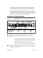
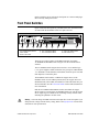
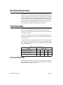
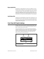
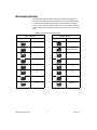
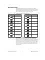
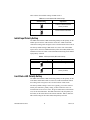
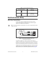
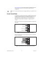
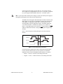
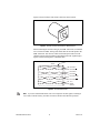
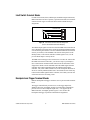
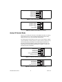
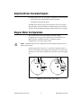
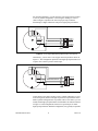
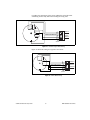
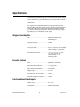
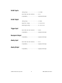
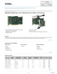
USER GUIDE
MID-7604/7602 POWER DRIVE
This user guide describes the electrical and mechanical aspects of the
MID-7604/7602 power drive and describes how to use the MID-7604/7602
with your motion controller.
Contents
Conventions ............................................................................................ 2
Introduction ............................................................................................. 2
What You Need to Get Started ............................................................... 3
Safety Information .................................................................................. 3
Installation and Connector Wiring.......................................................... 4
Front Panel Switches............................................................................... 5
Host Bus Interlock Circuit ...................................................................... 6
Front Panel LEDs.................................................................................... 6
Driver Fault Output LEDs ............................................................... 6
Driver Inhibit LEDs ......................................................................... 7
Limit Status LEDs ........................................................................... 7
Front Panel DIP Switch Settings............................................................. 7
Microstepping Selection .................................................................. 8
Output Current Settings ................................................................... 9
Inhibit Input Polarity Setting ........................................................... 10
Limit Status LED Polarity Setting ................................................... 10
Back Panel Connector Wiring................................................................. 11
Motor Power Terminal Blocks ........................................................ 11
Encoder Terminal Blocks ................................................................ 12
Limit Switch Terminal Blocks......................................................... 15
Breakpoint and Trigger Terminal Blocks ........................................ 15
Analog I/O Terminal Blocks............................................................ 16
Amplifier/Driver Command Signals....................................................... 17
Stepper Motor Configurations ................................................................ 17
Specifications .......................................................................................... 20
Support Information................................................................................ 24
National Instruments ™ and ni.com ™ are trademarks of National Instruments Corporation. Product and company names mentioned herein are
trademarks or trade names of their respective companies.
322454B-01
© Copyright 1999 National Instruments Corp. All rights reserved.
December 1999
Conventions
The following conventions are used in this manual:
This icon denotes a note, which alerts you to important information.
This icon denotes a caution, which advises you of precautions to take to
avoid injury, data loss, or a system crash.
This icon denotes a warning, which advises you of precautions to take to
avoid being electrically shocked.
italic
Italic text denotes emphasis, a cross reference, or an introduction to a key
concept. This font also denotes text that is a placeholder for a word or value
that you must supply.
overline
Indicates the signal is active-low.
Introduction
Your MID-7604/7602 power drive is a complete power amplifier and
system interface for use with four or two axes of simultaneous stepper
motion control. Ideally suited to industrial and laboratory applications, the
MID-7604/7602 has everything you need to connect motors, encoders,
limit switches, I/O, and other motion hardware to National Instruments
motion controllers.
The MID-7604/7602 can drive a broad range of stepper motors with its
rugged microstepping bipolar chopper driver and user-selectable
current-per-phase settings. In all configurations, power supplies are built in
and use standard 240/120 VAC for operation. Electronics are fan cooled to
assure reliable operation.
The MID-7604/7602 simplifies your field wiring through separate encoder,
limit switch, and motor power removable screw terminal connector blocks
for each axis. The terminal blocks do not require any special wiring tools
for installation. The MID-7604/7602 connects to National Instruments
motion controllers via a 68-pin, high-density interconnect cable.
The MID-7604/7602 has four levels of amplifier inhibit/disable protection
for motion system shut down. The front panel contains both enable and
power switches for direct motor inhibiting and system power-down
operations. The MID-7604/7602 also has a host bus power interlock that
activates an internal driver inhibit signal if the host computer is shut down
or the motion controller interface cable is disconnected. The inhibit input
MID-7604/7602 Power Drive
2
www.ni.com
from the back panel connectors also inhibits the stepper drives when
activated.
The MID-7604/7602 is packaged in a rugged, lightweight enclosure that
can be used as a benchtop unit or that can be rack-mounted using a 19-in.
standard rack kit.
What You Need to Get Started
To set up and use your MID-7604/7602 accessory, you must have the
following items:
❑ The MID-7604/7602 accessory and MID-7604/7602 Power Drive
User Guide
❑ Power cord (IEC type)
❑ One of the following shielded cable assemblies, as applicable:
•
SH68-C68-S, part number 186381-02
•
SHC68-C68-S, part number 186380-02
Refer to the Specifications section later in this guide for detailed
specifications for the MID-7604/7602.
Safety Information
Warnings Keep away from live circuits. Do not remove equipment covers or shields unless
you are trained to do so. Hazardous voltages may exist even when the equipment is turned
off. To avoid a shock hazard, do not perform procedures involving cover or shield removal
unless you are qualified to do so and disconnect all field power prior to removing covers
or shields.
Do not operate damaged equipment. The safety protection features built into this device
can become impaired if the device becomes damaged in any way. If the device is damaged,
turn the device off and do not use it until service-trained personnel can check its safety. If
necessary, return the device to National Instruments for service and repair to ensure that its
safety is not compromised.
Do not operate this equipment in a manner that contradicts the information specified in this
document. Misuse of this equipment could result in a shock hazard.
Do not substitute parts or modify equipment. Because of the danger of introducing
additional hazards, do not install unauthorized parts or modify the device. Return the
device to National Instruments for service and repair to ensure that its safety features are
not compromised.
© National Instruments Corporation
3
MID-7604/7602 Power Drive
When connecting or disconnecting signal lines to the MID-7604/7602 terminal block
screw terminals, make sure the lines are powered off. Potential differences between the
lines and the MID-7604/7602 ground create a shock hazard while you connect the lines.
Connections, including power signals to ground and vice versa, that exceed any of the
maximum signal ratings on the MID-7604/7602 device can create a shock or fire hazard or
can damage any or all of the motion controllers connected to the MID-7604/7602 chassis,
the host computer, and the MID-7604/7602 device. National Instruments is not liable for
any damages or injuries resulting from incorrect signal connections.
Installation and Connector Wiring
Figure 1 shows connectors located on the back panel of your
MID-7604/7602.
7
1
1
2
3
4
5
6
2
3
4
Motion Controller Connector
Analog Input Connector
Analog Output Connector
Trigger Connector
Breakpoint Connector
AC Power
5
8
9
11
12
Encoder
Connectors
7 Axis 1
8 Axis 2
9 Axis 3
10 Axis 4
10
15
13
16
17
18
6
14
Limit
Connectors
11 Axis 1
12 Axis 2
13 Axis 3
14 Axis 4
Motor
Connectors
15 Axis 1
16 Axis 2
17 Axis 3
18 Axis 4
Figure 1. MID-7604/7602 Back Panel Connectors
Caution Be sure to turn off the enable switch and the main AC power to your
MID-7604/7602 and host computer before connecting the accessory to your motion
controller.
Connect the motion controller to the MID-7604/7602 with the interface
cable. Wire the motor power, limit switch, encoder, and I/O terminal blocks
as described in this document and to your specific system requirements.
Use the LINE VOLTAGE SELECT switch to configure the
MID-7604/7602 for 120 VAC, 60 Hz or 240 VAC, 50 Hz operation. For
proper operation, you must set this switch to match your power source.
You must change the MID-7604/7602 main input fuse on the front panel if you
change the line voltage from the factory setting. Refer to the Specifications section of this
document for fuse specifications.
Warning
MID-7604/7602 Power Drive
4
www.ni.com
Finally, install the power cord into the back panel AC connector and plug it
into a correctly rated power source.
Front Panel Switches
Figure 2 shows the front panel for your MID-7604/7602. The DIP switches
are shown with the detachable metal cover plate removed.
AXIS CONFIGURATION
LINE VOLTAGE SELECT
AC POWER
FUSE
ENABLE
FAULTS
INHIBITS
ON
ON
1
1
2
3
4
2
OFF
3
ON
ON
LIMITS
1
+5V
ON
4
Main Input Fuse
Line Voltage Select Switch
Power Switch
Green Power LED
ON
OFF
5
5
6
7
6
7
Enable Switch
Axis 1 DIP Switch Bank
Axis 2 DIP Switch Bank
8
9
2
3
AXIS
4
10
8 Axis 3 DIP Switch Bank
9 Axis 4 DIP Switch Bank
10 LED Status Array
Figure 2. MID-7604/7602 Front Panel
There are two rocker switches on the MID-7604/7602 front panel:
AC POWER and ENABLE. Refer to Figure 2 for the location of these
switches.
The AC POWER switch energizes the motor bus (+24 V) and the logic
(+5 V) power supplies. When switched on, the green power LED labelled
+5 V illuminates. If this LED fails to illuminate, check the power cord and
main input fuse on the front panel.
The ENABLE switch enables or inhibits the stepper drivers. If the
ENABLE switch is in the inhibit position (OFF), the stepper drivers are
inhibited and the yellow LEDs, the middle row of the LED status array, for
all axes illuminate. See the Front Panel LEDs section of this document for
more information.
Both the AC POWER and ENABLE switches can inhibit the stepper
drivers. However, as long as the AC POWER switch is on, only the stepper
driver output stages are disabled. The remaining circuitry remains active,
including the quadrature encoder circuit.
You must change the MID-7604/7602 main input fuse on the front panel if you
change the line voltage from the factory setting. Refer to the Specifications section of this
document for fuse specifications.
Warning
© National Instruments Corporation
5
MID-7604/7602 Power Drive
Host Bus Interlock Circuit
The MID-7604/7602 has a host bus interlock circuit that monitors the
presence of +5 V from the host computer and disables the MID-7604/7602
when the voltage is not present or falls out of tolerance. This circuit shuts
down the stepper drives for all axes by activating the inhibit when the host
computer is disconnected from the MID-7604/7602 or inadvertently shut
down. Activation of the host bus interlock circuitry illuminates the yellow
LEDs (middle row) of the LED status array for all axes. See the Front
Panel LEDs section of this document for more information.
Front Panel LEDs
The front panel LEDs consist of a single green LED to indicate if the main
power is active and an LED status array of 3 rows by 4 columns that
provides a variety of status information. Refer to Figure 2 for the location
of the front panel LEDs.
If the DC power supplies are active, the green power LED illuminates. If
this LED fails to illuminate, check the power cord and the main input fuse
on the front panel.
The LED status array is arranged by motor axes. Each of the four columns
represents an axis, and each of the three rows represents a particular status.
Table 1 summarizes the axes and statuses to which the different LEDs in the
3 × 4 array correspond.
Table 1. Front Panel LED Indicators
Status
Motor Axis
Driver Fault Output (red)
1
2
3
4
Driver Inhibit (yellow)
1
2
3
4
Limit Status (green)
1
2
3
4
Driver Fault Output LEDs
The top row of LEDs indicates the status of the stepper drivers. When an
LED illuminates red, there is either an overcurrent condition or a problem
with the motor bus voltage on that axis.
MID-7604/7602 Power Drive
6
www.ni.com
Driver Inhibit LEDs
The middle row of LEDs indicates if a motor axis is inhibited. An axis is
inhibited and the LED illuminates yellow if the host bus interlock circuitry
is activated from the back panel, if the ENABLE switch on the front panel
is in the inhibit position, if the motion controller’s inhibit signal is low, or
if the per-axis inhibit input is actively driven. The polarity of the per-axis
inhibit input is selectable from the front panel DIP switches. See the Front
Panel DIP Switch Settings section of this document for more information.
Limit Status LEDs
The bottom row of LEDs indicates if a limit switch is currently active. The
LED illuminates green if either the forward or reverse limit switch is active
for each axis. You can select the polarity for the limit status LEDs from the
front panel DIP switches. See the Front Panel DIP Switch Settings of this
document for more information.
Front Panel DIP Switch Settings
The MID-7604/7602 front panel has a detachable metal plate that, when
removed, provides access to four 10-position DIP switch banks. Refer to
Figure 2 for the location of these switches.
Use the first nine DIP switches on each 10-position DIP switch bank to
configure the microstep rate, peak output current, and current reduction for
each axis. The DIP switch banks for axes 1 and 2 contain a global DIP
switch, switch 10, which sets the polarity of the inhibit input and the
polarity of the limit status LED, respectively.
1
O 1
N
2
2
3
4
5
6
7
8
9 10
3
1
2
3
Peak Current Output Switches
Microstep Rate Switches
Current Reduction Switch
4
4
Global Polarity Switch (unused on
axes 3 and 4 DIP switch banks)
Figure 3. DIP Switch Bank Layout
© National Instruments Corporation
7
MID-7604/7602 Power Drive
Microstepping Selection
The MID-7604/7602 uses bipolar chopper, two-phase microstepping
drivers with a broad range of microstep rates. The factory-default setting
is 10-times microstepping (2,000 steps/rev with standard 1.8º stepper
motors). Table 2 shows the DIP switch settings for all possible microstep
settings. DIP switches 6 through 9 control the microstep rate on a per-axis
basis.
Table 2. Microstep Rate DIP Switch Setting
Binary Selections
Switch
Decimal Selections
Microsteps/Step
Switch
2 (half step)
O
N
6 7 8 9
4
O
N
O
N
6 7 8 9
6 7 8 9
8
O
N
6 7 8 9
16
6 7 8 9
32
6 7 8 9
64
6 7 8 9
128
6 7 8 9
256
Do not use
O
N
6 7 8 9
6 7 8 9
MID-7604/7602 Power Drive
Do not use
O
N
6 7 8 9
O
N
250
O
N
6 7 8 9
O
N
125
O
N
6 7 8 9
O
N
50
O
N
6 7 8 9
O
N
10
(factory default)
25
O
N
6 7 8 9
O
N
5
O
N
6 7 8 9
Microsteps/Step
8
www.ni.com
Output Current Settings
The MID-7604/7602 can provide 0.20–1.4 A peak (0.14–1 A RMS)
depending on the peak output current DIP switch settings for each axis. DIP
switches 1 through 4 control the peak output current. Table 3 shows the DIP
switch settings for all possible peak output current settings.
Table 3. Peak Output Current DIP Switch Setting
Switch
Peak Output (A)
Switch
1.40
O
N
1 2 3 4
1.20
O
N
1 2 3 4
1.00
O
N
0.28
O
N
1 2 3 4
1 2 3 4
0.85
O
N
0.27
O
N
1 2 3 4
1 2 3 4
0.70
O
N
0.25
O
N
1 2 3 4
1 2 3 4
0.60
O
N
0.24
O
N
1 2 3 4
1 2 3 4
0.55
O
N
0.23
O
N
1 2 3 4
1 2 3 4
0.30
O
N
1 2 3 4
O
N
0.35
O
N
1 2 3 4
Peak Output (A)
1 2 3 4
0.50
(factory default)
0.20
O
N
1 2 3 4
You can configure the MID-7604/7602 stepper drivers in a current
reduction mode on a per-axis basis. This is useful to minimize motor
heating when you are not stepping. When current reduction is enabled, the
current decreases by 50% when no stepping has occurred for approximately
500 ms. DIP switch 5 controls current reduction on a per-axis basis. When
this DIP switch is on, current reduction is enabled. When this DIP switch
is off, current reduction is disabled. The factory default setting is current
reduction enabled.
© National Instruments Corporation
9
MID-7604/7602 Power Drive
Table 4 shows the available settings for DIP switch 5.
Table 4. Current Reduction DIP Switch Settings
Switch Setting
Operation
Current reduction enabled
(factory default)
O
N
5
Current reduction disabled
O
N
5
Inhibit Input Polarity Setting
The MID-7604/7602 has a DIP switch that globally sets the polarity for the
inhibit input for all axes. DIP switch 10 on the axis 1 DIP switch bank
controls this setting. Refer to Figures 2 and 3 for the location of this switch.
The factory-default setting of DIP switch 10 is active-low. If the inhibit
input is active, the axis is inhibited and the yellow status LED (middle row)
illuminates for the axis. Table 5 shows the DIP switch setting for the inhibit
input polarity selection.
Table 5. Inhibit Input Polarity DIP Switch Settings
Axis 1 Switch Setting
Operation
Active-high
O
N
10
Active-low
(factory default)
O
N
10
Limit Status LED Polarity Setting
The MID-7604/7602 has a DIP switch that globally sets the polarity for the
Limit Status LED. DIP switch 10 on the axis 2 DIP switch bank controls
this setting. Refer to Figures 2 and 3 for the location of this switch.
The factory-default setting is active-low. Typically, you set the switch to
match your controller’s polarity setting, so that if either the reverse or
forward limits for an axis are active, the green status LED (on the bottom
row) for the axis illuminates. This DIP switch alters only the polarity for
the LEDs, not the actual limit to the motion controller. Table 6 shows the
DIP switch setting for the Limit Status LED polarity selection.
MID-7604/7602 Power Drive
10
www.ni.com
Table 6. Limit Status LED DIP Switch Settings
Axis 2 Switch Setting
Operation
Active-high
O
N
10
Active-low
(factory default)
O
N
10
Back Panel Connector Wiring
Motor Power Terminal Blocks
For motor power wiring, each MID-7604/7602 axis has a separate
5-position removable screw terminal block. Figure 4 shows a typical
stepper motor configuration pin assignment.
Note The dotted loop indicates a shielded cable. A lin e above a signal indicates that the
signal is active-low.
Phase A
Phase A
Case Ground
Phase B
Phase B
Stepper Motor
1
2
3
4
5
Shield
Figure 4. Typical Full-Coil Stepper Motor (2-Phase Type)
Terminal Block Pin Assignment
Use shielded, 20 AWG wire or larger for the motor power cable. If
available, you should connect a case ground wire to pin 3 (Ground/Shield);
this helps to avoid ground loops and signal noise problems. Case ground
connects to the motor housing, and not to any of the motor power terminals.
The MID-7604/7602 contains bipolar chopper drivers. You must wire the
stepper motors in a 4-wire configuration as shown in Figure 4. You must
isolate unused lead wires and leave them disconnected. See the Stepper
© National Instruments Corporation
11
MID-7604/7602 Power Drive
Motor Configurations section in this document for additional information
on connecting 6- and 8-wire motors and on the alternate half-coil
configuration.
Caution
Never connect unused center taps or winding terminals to pin 3 (ground) or each
other.
Encoder Terminal Blocks
For quadrature incremental encoder signals, each MID-7604/7602 axis has
a separate 8-position removable screw terminal block. Where applicable,
the MID-7604/7602 accepts two types of encoder signal inputs:
single-ended (TTL) or differential line driver. You can accommodate
open-collector output encoders by using 2.2 kΩ pullup resistors to
+5 VDC.
Figure 5 shows the typical encoder wiring pin assignment for single-ended
signal input.
Encoder A
Encoder B
Encoder Index
+5 V
Digital Ground
1
2
3
4
5
6
7
8
Figure 5. Typical Single-Ended Encoder Wiring Pin Assignment
Figure 6 shows the typical encoder wiring pin assignment for differential
line driver signal inputs.
Encoder A
Encoder A
Encoder B
Encoder B
Encoder Index
Encoder Index
+5 V
Digital Ground
1
2
3
4
5
6
7
8
Figure 6. Typical Differential Line Driver Encoder Wiring Pin Assignment
MID-7604/7602 Power Drive
12
www.ni.com
If the encoder cable length is greater than 10 ft, use encoders with line
driver outputs for your applications. Power for a +5 V encoder—generated
by a power supply inside the MID-7604/7602—is available on pin 7.
Note If you require other encoder power voltages, reference an external power supply to
the Digital Ground signal on the 8-pin encoder terminal block.
The MID-7604/7602 supports differential inputs for Phase A, Phase B, and
Index signals. You can easily accommodate encoders with various phase
relationships by swapping the signals and/or connecting them to the
inverting inputs as specific applications require. The Index signal must
occur when both Phase A and Phase B signals are low, as shown in
Figure 7. If the Index polarity is inverted, try reversing the Index and Index
signals on differential encoders or using the Index input on single-ended
encoders.
Figure 7 shows the proper encoder phasing for CW (forward) motor
rotation.
Phase A
Phase B
Index
Figure 7. Encoder Signal Phasing, CW Rotation
Closed-loop stepper applications require consistent directional polarity
between the motor and encoder for correct operation. The National
Instruments motion control standard directional polarity is as follows:
•
Positive = forward = clockwise (CW) facing motor shaft
•
Negative = reverse = counter-clockwise (CCW) facing motor shaft
© National Instruments Corporation
13
MID-7604/7602 Power Drive
Figure 8 shows clockwise and counter-clockwise motor rotation.
W
C
W
C
C
Figure 8. Clockwise and Counter-Clockwise Motor Rotation
When connecting the encoder wiring to your MID-7604/7602, use shielded
wire of at least 24 AWG. Analog noise filters filter the encoder inputs in the
MID-7604/7602. You must use cables with twisted pairs and an overall
shield for improved noise immunity and enhanced encoder signal integrity.
Figure 9 shows twisted pairs in a shielded cable.
Drain
Shield
Encoder A
Encoder A
Encoder B
Encoder B
Encoder Index
Encoder Index
+5 V
Digital
Ground
Figure 9. Shielded Twisted Pairs
Note If you use an unshielded cable, noise can corrupt the encoder signals, resulting in
lost counts, reduced accuracy, and other erroneous encoder and controller operation.
MID-7604/7602 Power Drive
14
www.ni.com
Limit Switch Terminal Blocks
For end-of-travel limit, home, inhibit input, and inhibit output connections,
MID-7604/7602 axes have a separate, 6-position removable screw terminal
connector block. Figure 10 shows the limit switch terminal block pin
assignments.
Forward Limit
Home Input
Reverse Limit
Inhibit Input
Inhibit Output
Digital Ground
1
2
3
4
5
6
Figure 10. Limit Switch Terminal Block Pin Assignment
(Passive Limit Switch Connection Example)
The inhibit output signal is asserted low from the MID-7604/7602 when an
axis is inhibited. This signal can be useful for actuating mechanical brakes
or for monitoring an axis status. An axis is inhibited if the host bus interlock
circuitry is activated, if the ENABLE switch on the front panel is in the
inhibit position, if the motion controller’s inhibit signal is low, or if the
per-axis inhibit input is actively driven.
The MID-7604/7602 stepper drive remains in a reset state for 500 ms after
the inhibit is deasserted. Therefore, you can lose steps if you attempt to
issue a start motion command within 500 ms from the deassertion of the
stepper drive inhibit. A Kill command asserts the inhibit signal from the
controller and a Halt command deasserts the inhibit signal from the
controller. The yellow LEDs (middle row) on the front panel illuminate if
an axis is currently inhibited (killed state). You should execute a halt stop
to deassert the inhibit signal from the controller, after which you must wait
at least 500 ms before executing a start.
Breakpoint and Trigger Terminal Blocks
Both the breakpoint and trigger connectors use a 6-pin removable terminal
block.
The trigger terminal block provides access to the trigger input lines,
shutdown input line, and digital ground. The breakpoint terminal block
provides access to the breakpoint output lines, +5 V supplied by the
MID-7604/7602, and digital ground. Figures 11 and 12 show the
breakpoint and trigger 6-position terminal block assignments.
© National Instruments Corporation
15
MID-7604/7602 Power Drive
Trigger Input 1
Trigger Input 2
Trigger Input 3
Trigger Input 4
Shutdown Input
Digital Ground
1
2
3
4
5
6
Figure 11. Trigger Terminal Block Pin Assignment
Breakpoint Output 1
Breakpoint Output 2
Breakpoint Output 3
Breakpoint Output 4
+5 V
Digital Ground
1
2
3
4
5
6
Figure 12. Breakpoint Terminal Block Pin Assignment
Analog I/O Terminal Blocks
There are two analog I/O connectors on the MID-7604/7602. The analog
input connector uses a 6-pin removable terminal block and the analog
output connector uses a 5-pin removable terminal block.
The analog input terminal block provides access to four analog-to-digital
converter channels, an analog reference voltage from the converter circuit,
and an analog input ground signal. The analog output terminal block
provides access to four digital-to-analog converter channels with ±10 V
output range and analog output ground. Refer to Figures 13 and 14 for
terminal block pin assignments.
Analog Input 1
Analog Input 2
Analog Input 3
Analog Input 4
Analog Reference (Output)
Analog Input Ground
1
2
3
4
5
6
Figure 13. Analog Input Terminal Block Pin Assignment
Analog Output 1
Analog Output 2
Analog Output 3
Analog Output 4
Analog Output Ground
1
2
3
4
5
Figure 14. Analog Output Terminal Block Pin Assignment
MID-7604/7602 Power Drive
16
www.ni.com
Amplifier/Driver Command Signals
For stepper drivers, there are two industry standards for command signals:
•
Step and Direction signals (MID-7604/7602 standard)
•
Independent CW and CCW pulses
The MID-7604/7602 uses stepper drivers that have active-low step and
direction inputs. You must configure the stepper outputs of your motion
controller for Step and Direction signals with inverted (active-low) polarity.
Stepper Motor Configurations
This section describes the various industry-standard winding
configurations for stepper motors and shows how to connect them to a
MID-7604/7602. The MID-7604/7602 is compatible with all
configurations of two-phase stepper motors.
The MID-7604/7602 is not compatible with 5-lead unipolar stepper motors or
5-phase stepper motors.
Caution
2-phase stepper motors come in 4-, 6-, and 8-wire variations. Figure 15
shows a 6-wire and an 8-wire stepper motor respectively. A 4-wire motor is
the same as a 6-wire motor except that the center taps (CT) are not brought
out.
Phase A
Phase A-CT
Phase A-CT
Phase A
Phase A
Phase A-CT
Phase A-CT
Phase A
Phase B
Phase B
Phase B-CT
Phase B-CT
Phase B-CT
Phase B-CT
Phase B
Phase B
6-wire
8-wire
Figure 15. 6-Wire and 8-Wire Stepper Motors
© National Instruments Corporation
17
MID-7604/7602 Power Drive
For maximum flexibility, you can connect 8-wire stepper motors in either
a series or parallel configuration. Connecting the windings in series as
shown in Figure 16 produces the most torque per amp, but has the
disadvantage of higher inductance and poorer high-speed performance.
Phase A
Phase A-CT
Phase A-CT
Phase A
Phase B
1
2
3
4
5
Phase B-CT
Phase B-CT
Motor Case Ground
Phase B
Phase A
Phase A
Ground
Phase B
Phase B
Shield
Figure 16. Series Stepper Motor Wiring (Higher Torque, Lower Speed)
Alternatively, you can wire 8-wire stepper motors in parallel as shown in
Figure 17. This configuration produces better high-speed performance but
requires more current to produce rated torque.
Phase A
Phase A-CT
Phase A-CT
Phase A
Phase B
1
2
3
4
5
Phase B-CT
Phase B-CT
Motor Case Ground
Phase B
Phase A
Phase A
Ground
Phase B
Phase B
Shield
Figure 17. Parallel Stepper Motor Wiring (Higher Speed, Lower Torque)
Notice that an 8-wire motor wired in series is virtually identical to a 6-wire
motor and typically has the same high-torque but low-speed characteristics.
While a parallel configuration is not possible with a 6-wire motor, you can
usually obtain high-speed performance with the half-coil connection shown
in Figure 18. This configuration sacrifices low-speed torque for better
high-speed performance. With this configuration, it is typically not possible
MID-7604/7602 Power Drive
18
www.ni.com
to produce the rated torque of the motor without the risk of the motor
overheating because only half of the windings are being used.
Phase A
Phase A-CT
Phase A-CT
Phase A
Phase B
1
2
3
4
5
Phase B-CT
Phase B-CT
Motor Case Ground
Phase B
Phase A
Phase A
Ground
Phase B
Phase B
Shield
Figure 18. Half-Coil Stepper Motor Wiring
Figure 19 shows the wiring for a typical 4-wire motor.
Phase A
Phase A
Phase B
1
2
3
4
5
Motor Case Ground
Phase B
Phase A
Phase A
Ground
Phase B
Phase B
Shield
Figure 19. 4-Wire Motor Wiring
© National Instruments Corporation
19
MID-7604/7602 Power Drive
Specifications
The following specifications apply only to the MID-7604/7602. To obtain
a system specification, you must account for your motion controller. Please
refer to your controller specifications to determine overall system
specifications.
Some signals have compatibility defined as signal pass-through. This
means the MID-7604/7602 may have passive filtering on these signals but
will not affect the voltage range or current handling capability. Consult
your motion controller specifications to determine the allowable voltage
range and logic level compatibility of the signal.
Stepper Drive Amplifier
Type ........................................................IM481H modular hybrid,
bipolar chopper
Chopping frequency ...............................20 kHz
Motor bus voltage ...................................24 VDC nominal
Current per phase....................................0.20–1.4 A peak (0.14–1 A RMS)
(factory setting is 0.50 A peak)
Microstepping selections ........................×2, 4, 8, 16, 32, 64, 128, 256
×5, 10, 25, 50, 125, 250
(factory default is ×10
microsteps/step)
Encoder Interface
Inputs ......................................................Quadrature, incremental
Differential input threshold ....................± 0.3V (typical)
Single ended input threshold ..................TTL/CMOS
Voltage range..........................................0–5 VDC
Noise filter (RC time constant)...............100 ns
Maximum quadrature frequency.............1 MHz
Limit and Home Switch Inputs
Voltage range..........................................0–12 VDC
Compatibility ..........................................Signal pass-through
MID-7604/7602 Power Drive
20
www.ni.com
Inhibit Inputs
Voltage range ......................................... 0–12 VDC
Noise filter (RC time constant) .............. 10 µs
Compatibility ......................................... Signal pass-through
Inhibit Output
Voltage range ......................................... 0–5 VDC
Output low voltage................................. 0.5 V at 64 mA
Output high voltage................................ 2.4 V at 32 mA
Trigger Input
Noise filter (RC time constant) .............. 100 ns
Compatibility ......................................... Signal pass-through
Breakpoint Output
Compatibility ......................................... Signal pass-through
Analog Input
Noise filter (RC time constant) .............. 10 µs
Compatibility ......................................... Signal pass-through
Analog Output
Compatibility ......................................... Signal pass-through
© National Instruments Corporation
21
MID-7604/7602 Power Drive
Included Connectors
Encoders .................................................8-position mini-combicon
3.81 mm plug (1 per axis)
Limits......................................................6-position mini-combicon
3.81 mm plug (1 per axis)
Motors.....................................................5-position combicon 5.08 mm
plug (1 per axis)
Breakpoints .............................................6-position mini-combicon
3.81 mm plug (1 total)
Triggers...................................................6-position mini-combicon
3.81 mm plug (1 total)
Analog input ...........................................6-position mini-combicon
3.81 mm plug (1 total)
Analog output .........................................5-position mini-combicon
3.81 mm plug (1 total)
AC power................................................Detachable AC power cord
(IEC standard type)
Motion I/O ..............................................68-pin female high density
VHDCI type
Standards Compliance
Designed to meet UL Standard for Safety for Power Conversion
Equipment, UL 508C, and EN 50178—Electronic equipment for use in
power installations
Installation Category II, Pollution degree 2
CE compliant to ENC and low-voltage directives
Environment
Operating temperature ............................0 to 40 ºC (32 to 104 ºF)
Storage temperature ................................–20 to 70 ºC (–4 to 158 ºF)
Humidity .................................................10% to 90% (noncondensing)
MID-7604/7602 Power Drive
22
www.ni.com
Power Supply
Input voltage .......................................... 90–138 VAC / 204–264 VAC,
47–63 Hz
Input fuse
120 VAC (factory default) .............. 6.3 A (Littelfuse #21506.3)
240 VAC ......................................... 4 A (Littelfuse #215004)
Input fuse dimensions ............................ 5 × 20 mm
Host Bus Voltage Interlock
PC bus host voltage threshold ................ 4.5 VDC
Physical
Length .................................................... 30.7 cm (12.1 in.)
Width...................................................... 25.4 cm (10 in.)
Height..................................................... 4.3 cm (1.7 in.)
Weight .................................................... 4.5 kg (10 lb.)
© National Instruments Corporation
23
MID-7604/7602 Power Drive
Support Information
Worldwide Technical Support and Product Information
www.ni.com
National Instruments Corporate Headquarters
11500 North Mopac Expressway
Austin, Texas 78759-3504
USA Tel: 512 794 0100
Worldwide Offices
Australia 03 9879 5166, Austria 0662 45 79 90 0, Belgium 02 757 00 20, Brazil 011 284 5011,
Canada (Ontario) 905 785 0085, Canada (Québec) 514 694 8521, China 0755 3904939, Denmark 45 76 26 00,
Finland 09 725 725 11, France 01 48 14 24 24, Germany 089 741 31 30, Hong Kong 2645 3186,
India 91805275406, Israel 03 6120092, Italy 02 413091, Japan 03 5472 2970, Korea 02 596 7456,
Mexico (D.F.) 5 280 7625, Mexico (Monterrey) 8 357 7695, Netherlands 0348 433466, Norway 32 27 73 00,
Singapore 2265886, Spain (Madrid) 91 640 0085, Spain (Barcelona) 93 582 0251, Sweden 08 587 895 00,
Switzerland 056 200 51 51, Taiwan 02 2377 1200, United Kingdom 01635 523545