1
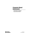
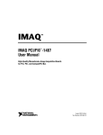
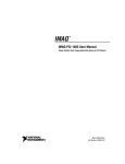
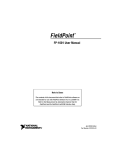
USER GUIDE
MID-7604/7602 POWER DRIVE
This user guide describes the electrical and mechanical aspects of the
MID-7604/7602 power drive and how to use the MID-7604/7602 with your
motion controller.
Contents
Compliance ............................................................................................. 2
Conventions ............................................................................................ 3
Introduction ............................................................................................. 4
What You Need to Get Started ............................................................... 4
Safety Information .................................................................................. 5
Front Panel Switches............................................................................... 7
Back Panel Connector Wiring................................................................. 8
Host Bus Interlock Circuit ...................................................................... 9
Front Panel LEDs.................................................................................... 9
Driver Fault Output LEDs ............................................................... 10
Driver Inhibit LEDs ......................................................................... 10
Limit Status LEDs ........................................................................... 10
Front Panel DIP Switch Settings............................................................. 11
Microstepping Selection .................................................................. 12
Output Current Settings ................................................................... 13
Inhibit Input Polarity Setting ........................................................... 15
Limit Status LED Polarity Setting ................................................... 15
Back Panel Connector Wiring................................................................. 16
Motor Power Terminal Blocks ........................................................ 16
Encoder Terminal Blocks ................................................................ 17
Limit Switch Terminal Blocks......................................................... 20
Breakpoint and Trigger Terminal Blocks ........................................ 20
Analog I/O Terminal Blocks............................................................ 21
Accessories for Optional Use.................................................................. 22
Strain-Relief Bar .............................................................................. 22
Panel-Mount Kit (Included)............................................................. 23
Amplifier/Driver Command Signals....................................................... 23
Stepper Motor Configurations ................................................................ 24
Specifications .......................................................................................... 27
National Instruments™, NI™, and ni.com™ are trademarks of National Instruments Corporation. Product and company names mentioned herein are
trademarks or trade names of their respective companies.
322454C-01
Copyright © 1999, 2001 National Instruments Corp. All rights reserved.
July 2001
Technical Support Resources ..................................................................31
NI Web Support................................................................................31
Worldwide Support ..........................................................................31
Compliance
FCC/Canada Radio Frequency Interference Compliance*
Determining FCC Class
The Federal Communications Commission (FCC) has rules to protect wireless communications from interference. The FCC
places digital electronics into two classes. These classes are known as Class A (for use in industrial-commercial locations only)
or Class B (for use in residential or commercial locations). Depending on where it is operated, this product could be subject to
restrictions in the FCC rules. (In Canada, the Department of Communications (DOC), of Industry Canada, regulates wireless
interference in much the same way.)
Digital electronics emit weak signals during normal operation that can affect radio, television, or other wireless products. By
examining the product you purchased, you can determine the FCC Class and therefore which of the two FCC/DOC Warnings
apply in the following sections. (Some products may not be labeled at all for FCC; if so, the reader should then assume these are
Class A devices.)
FCC Class A products only display a simple warning statement of one paragraph in length regarding interference and undesired
operation. Most of our products are FCC Class A. The FCC rules have restrictions regarding the locations where FCC Class A
products can be operated.
FCC Class B products display either a FCC ID code, starting with the letters EXN,
or the FCC Class B compliance mark that appears as shown here on the right.
Consult the FCC web site http://www.fcc.gov for more information.
FCC/DOC Warnings
This equipment generates and uses radio frequency energy and, if not installed and used in strict accordance with the instructions
in this manual and the CE Mark Declaration of Conformity**, may cause interference to radio and television reception.
Classification requirements are the same for the Federal Communications Commission (FCC) and the Canadian Department
of Communications (DOC).
Changes or modifications not expressly approved by National Instruments could void the user’s authority to operate the
equipment under the FCC Rules.
Class A
Federal Communications Commission
This equipment has been tested and found to comply with the limits for a Class A digital device, pursuant to part 15 of the FCC
Rules. These limits are designed to provide reasonable protection against harmful interference when the equipment is operated
in a commercial environment. This equipment generates, uses, and can radiate radio frequency energy and, if not installed and
used in accordance with the instruction manual, may cause harmful interference to radio communications. Operation of this
equipment in a residential area is likely to cause harmful interference in which case the user will be required to correct
the interference at his own expense.
Canadian Department of Communications
This Class A digital apparatus meets all requirements of the Canadian Interference-Causing Equipment Regulations.
Cet appareil numérique de la classe A respecte toutes les exigences du Règlement sur le matériel brouilleur du Canada.
Class B
Federal Communications Commission
This equipment has been tested and found to comply with the limits for a Class B digital device, pursuant to part 15 of the
FCC Rules. These limits are designed to provide reasonable protection against harmful interference in a residential installation.
This equipment generates, uses and can radiate radio frequency energy and, if not installed and used in accordance with the
instructions, may cause harmful interference to radio communications. However, there is no guarantee that interference will not
occur in a particular installation. If this equipment does cause harmful interference to radio or television reception, which can
be determined by turning the equipment off and on, the user is encouraged to try to correct the interference by one or more of
the following measures:
• Reorient or relocate the receiving antenna.
• Increase the separation between the equipment and receiver.
MID-7604/7602 Power Drive
2
ni.com
•
•
Connect the equipment into an outlet on a circuit different from that to which the receiver is connected.
Consult the dealer or an experienced radio/TV technician for help.
Canadian Department of Communications
This Class B digital apparatus meets all requirements of the Canadian Interference-Causing Equipment Regulations.
Cet appareil numérique de la classe B respecte toutes les exigences du Règlement sur le matériel brouilleur du Canada.
European Union - Compliance to EU Directives
Readers in the EU must refer to the Manufacturer's Declaration of Conformity (DoC) for information** pertaining to the CE
Mark compliance scheme. The Manufacturer includes a DoC for most every hardware product except for those bought for
OEMs, if also available from an original manufacturer that also markets in the EU, or where compliance is not required as for
electrically benign apparatus or cables.
* Certain exemptions may apply in the USA, see FCC Rules §15.103 Exempted devices, and §15.105(c). Also available in
sections of CFR 47.
** The CE Mark Declaration of Conformity will contain important supplementary information and instructions for the user or
installer.
Conventions
This guide uses the following conventions:
This icon denotes a note, which alerts you to important information.
This icon denotes a caution, which advises you of precautions to take to
avoid injury, data loss, or a system crash.
This icon denotes a temperature caution, which advises you of precautions
to take to avoid a burn hazard.
This icon denotes a warning, which advises you of precautions to take to
avoid being electrically shocked.
bold
Bold text denotes items that you must select or click on in the software,
such as menu items and dialog box options. Bold text also denotes
parameter names.
italic
Italic text denotes emphasis, a cross reference, or an introduction to a key
concept. This font also denotes text that is a placeholder for a word or value
that you must supply.
monospace
Text in this font denotes text or characters that you should enter from the
keyboard, sections of code, programming examples, and syntax examples.
This font is also used for the proper names of disk drives, paths, directories,
programs, subprograms, subroutines, device names, functions, operations,
variables, filenames and extensions, and code excerpts.
© National Instruments Corporation
3
MID-7604/7602 Power Drive
Introduction
National Instruments’ MID-7604/7602 power drive is a complete power
amplifier and system interface for use with four or two axes of
simultaneous stepper motion control. Ideally suited to industrial and
laboratory applications, the MID-7604/7602 has everything you need to
connect motors, encoders, limit switches, I/O, and other motion hardware
to National Instruments’ motion controllers.
The MID-7604/7602 can drive a broad range of stepper motors with its
rugged microstepping bipolar chopper driver and user-selectable
current-per-phase settings. In all configurations, power supplies are built-in
and use standard 230/115 VAC for operation. Electronics are fan-cooled to
assure reliable operation.
The MID-7604/7602 simplifies field wiring through separate encoder, limit
switch, and motor power removable screw terminal connector blocks for
each axis. The terminal blocks do not require special wiring tools for
installation. The MID-7604/7602 connects to National Instruments’
motion controllers via a 68-pin, high-density interconnect cable.
The MID-7604/7602 has four levels of amplifier inhibit/disable protection
for motion system shutdown. The front panel contains both enable and
power switches for direct motor inhibiting and system power-down
operations. The MID-7604/7602 also has a host bus power interlock that
activates an internal driver inhibit signal if the host computer is shut down
or the motion controller interface cable is disconnected. The inhibit input
from the back panel connectors also inhibits the stepper drives when
activated.
The MID-7604/7602 is packaged in a rugged, lightweight enclosure that
can be used as a benchtop unit, panel mounted using a panel-mount kit, or
rack mounted using a 19-inch standard rack kit.
What You Need to Get Started
To set up and use your MID-7604/7602 accessory, you must have the
following items:
❑ MID-7604/7602 power drive
❑ MID-7604/7602 Power Drive User Guide
❑ Power cord (IEC type)
❑ Panel-mount kit (part number 187243-01)
MID-7604/7602 Power Drive
4
ni.com
❑ One of the following shielded cable assemblies, as applicable:
–
SH68-C68-S (part number 186381-02)
–
SHC68-C68-S (part number 186380-02)
Detailed specifications for the MID-7604/7602 are in the Specifications
section in this guide.
Safety Information
The following paragraphs contain important safety information you must follow
when installing and operating the device.
Caution
Do not operate the device in a manner not specified in the documentation.
Misuse of the device may result in a hazard and may compromise the safety
protection built into the device. If the device is damaged, turn it off and do
not use it until service-trained personnel can check its safety. If necessary,
return the device to National Instruments for repair.
Keep away from live circuits. Do not remove equipment covers or shields
unless you are trained to do so. If signal wires are connected to the device,
hazardous voltages can exist even when the equipment is turned off. To
avoid a shock hazard, do not perform procedures involving cover or shield
removal unless you are qualified to do so. Disconnect all field power prior
to removing covers or shields.
If the device is rated for use with hazardous voltages (>30 Vrms, 42.4 Vpk,
or 60 Vdc), it may require a safety earth-ground connection wire. See the
device specifications for maximum voltage ratings.
Because of the danger of introducing additional hazards, do not install
unauthorized parts or modify the device. Use the device only with the
chassis, modules, accessories, and cables specified in the installation
instructions. All covers and filler panels must be installed while operating
the device.
Do not operate the device in an explosive atmosphere or where flammable
gases or fumes may be present. Operate the device only at or below the
pollution degree stated in the specifications. Pollution consists of any
foreign matter—solid, liquid, or gas—that may reduce dielectric strength
or surface resistivity. Pollution degrees are listed below.
•
© National Instruments Corporation
Pollution Degree 1—No pollution or only dry, nonconductive
pollution occurs. The pollution has no effect.
5
MID-7604/7602 Power Drive
•
Pollution Degree 2—Normally only nonconductive pollution occurs.
Occasionally, nonconductive pollution becomes conductive because of
condensation.
•
Pollution Degree 3—Conductive pollution or dry, nonconductive
pollution occurs. Nonconductive pollution becomes conductive
because of condensation.
Clean the device and accessories by brushing off light dust with a soft,
nonmetallic brush. Remove other contaminants with a stiff, nonmetallic
brush. The unit must be completely dry and free from contaminants before
returning it to service.
You must insulate signal connections for the maximum voltage for which
the device is rated. Do not exceed the maximum ratings for the device.
Remove power from signal lines before connection to or disconnection
from the device.
The MID 7604/7602 drive is not a measurement device. However, if you
want to make a measurement of the circuits or devices connected to the
drive, operate the device only at or below the installation category stated in
the specifications. Installation categories are listed below.
1
•
Installation Category IV—for measurements performed at the source
of the low-voltage (<1000 V) installation. Examples include electricity
meters, measurements on primary overcurrent protection devices, and
ripple-control units.
•
Installation Category III—for measurements performed in the building
installation. Examples include measurements on distribution boards,
circuit-breakers, wiring (including cables), bus bars, junction boxes,
switches, socket outlets in the fixed installation, equipment for
industrial use, and some other types of equipment, such as stationary
motors permanently connected to the fixed installation.
•
Installation Category II—for measurements performed on circuits
directly connected to the low-voltage installation. Examples include
measurements on household appliances, portable tools, and other
similar equipment.
•
Installation Category I—for measurements performed on circuits not
directly connected to mains1. Examples include measurements on
circuits not derived from mains, and specially-protected (internal)
mains-derived circuits.
Mains is defined as the electricity supply system to which the equipment concerned is designed to be connected for either
powering the equipment or for measurement purposes.
MID-7604/7602 Power Drive
6
ni.com
The following is a diagram of a sample installation.
The stepper motor connectors on this drive are energized when the unit is
powered on. Disconnect the MID-7604/7602 unit from the power outlet before connecting
wires to or disconnecting wires from the stepper connectors. Strip back the insulation of
the stepper wires to the stepper connectors no more than 7 mm. Failure to do so could
result in electric shock leading to serious bodily injury or death.
Warning
The bottom surface of the MID-7604/7602 can get very hot to the touch under
certain conditions. To avoid a burn hazard, refer to the Output Current Settings section in
the Front Panel DIP Switch Settings section of this guide for the appropriate current setting
and safety hazards.
Caution
Front Panel Switches
Figure 1 shows the front panel of your MID-7604/7602. The DIP switches
are shown with the detachable metal cover plate removed.
AXIS CONFIGURATION
LINE VOLTAGE SELECT
AC POWER
FUSE
ENABLE
FAULTS
INHIBITS
ON
ON
1
1
2
3
4
2
OFF
3
Main Input Fuse
Line Voltage Select Switch
Power Switch
Green Power LED
ON
ON
ON
LIMITS
1
+5V
ON
4
OFF
5
5
6
7
6
7
Enable Switch
Axis 1 DIP Switch Bank
Axis 2 DIP Switch Bank
8
9
2
3
AXIS
4
10
8 Axis 3 DIP Switch Bank*
9 Axis 4 DIP Switch Bank*
10 LED Status Array
Figure 1. MID-7604/7602 Front Panel
Note
Items followed by an asterisk (*) are available on the MID-7604 only.
© National Instruments Corporation
7
MID-7604/7602 Power Drive
The two rocker switches on the MID-7604/7602 front panel are the
AC POWER and ENABLE. Figure 1 shows the location of these switches.
The AC POWER switch energizes the motor bus (+24 V) and the logic
(+5 V) power supplies. When switched on, the green power LED labeled
+5 V illuminates. If this LED fails to illuminate, check the power cord and
main input fuse on the front panel.
The ENABLE switch enables or inhibits the stepper drivers. If the
ENABLE switch is in the inhibit position (off), the stepper drivers are
inhibited, and the yellow LEDs (the middle row of the LED status array)
for all axes illuminate. See the Front Panel LEDs section of this guide for
more information.
Both the AC POWER and ENABLE switches can inhibit the stepper
drivers. However, as long as the AC POWER switch is on, only the stepper
driver output stages are disabled. The remaining circuitry remains active,
including the quadrature encoder circuit.
Caution You must change the MID-7604/7602 main input fuse on the front panel if you
change the line voltage from the factory setting. Refer to the Specifications section of this
guide for fuse specifications.
Back Panel Connector Wiring
Figure 2 shows connectors located on the back panel of your
MID-7604/7602.
7
1
1
2
3
4
5
6
2
3
4
Motion Controller Connector
Analog Input Connector
Analog Output Connector
Trigger Connector
Breakpoint Connector
AC Power
5
8
9
11
12
Encoder
Connectors
7 Axis 1
8 Axis 2
9 Axis 3*
10 Axis 4*
10
15
13
16
17
18
6
14
Limit
Connectors
11 Axis 1
12 Axis 2
13 Axis 3*
14 Axis 4*
Motor
Connectors
15 Axis 1
16 Axis 2
17 Axis 3*
18 Axis 4*
Figure 2. MID-7604/7602 Back Panel Connectors
Note Items followed by an asterisk (*) are available on the MID-7604 only.
MID-7604/7602 Power Drive
8
ni.com
Be sure to turn off the ENABLE switch and the main AC power to your
MID-7604/7602 and host computer before connecting the accessory to your motion
controller.
Caution
The stepper motor connectors on this drive are energized when the unit is
powered on. Disconnect the MID-7604/7602 unit from the power outlet before connecting
wires to or disconnecting wires from the stepper connectors. Strip back the insulation of
the stepper wires to the stepper connectors no more than 7 mm. Failure to do so could
result in electric shock leading to serious bodily injury or death.
Warning
1.
Use the interface cable to connect the motion controller to the
MID-7604/7602. Wire the motor power, limit switch, encoder, and I/O
terminal blocks as described in this guide and to your specific system
requirements.
2.
Use the LINE VOLTAGE SELECT switch to configure the
MID-7604/7602 for 115 VAC, 60 Hz or 230 VAC, 50 Hz operation.
For proper operation, you must set this switch to match your power
source.
Caution You must change the MID-7604/7602 main input fuse on the front panel if you
change the line voltage from the factory setting. Refer to the Specifications section of this
guide for fuse specifications.
3.
Finally, install the power cord into the back panel AC connector and
plug it in to a correctly rated power source.
Host Bus Interlock Circuit
The MID-7604/7602 has a host bus interlock circuit that monitors the
presence of +5 V from the host computer and disables the MID-7604/7602
when the voltage is not present or falls out of tolerance. This circuit shuts
down the stepper drives for all axes by activating the inhibit when the host
computer is disconnected from the MID-7604/7602 or inadvertently shut
down. Activation of the host bus interlock circuitry illuminates the yellow
LEDs (middle row) of the LED status array for all axes. See the Front Panel
LEDs section of this guide for more information.
Front Panel LEDs
The front panel LEDs consist of a single green LED to indicate if the main
power is active and an LED status array of 3 rows by 4 columns that
provides a variety of status information. Refer to Figure 1 for the location
of the front panel LEDs.
© National Instruments Corporation
9
MID-7604/7602 Power Drive
If the DC power supplies are active, the green power LED illuminates.
If this LED fails to illuminate, check the power cord and the main input
fuse on the front panel.
The LED status array is arranged by motor axes. Each of the four columns
represents an axis, and each of the three rows represents a particular status.
Table 1 summarizes the axis and status to which each LED in the 3 × 4
array corresponds.
Table 1. Front Panel LED Indicators
Status
Motor Axis
Driver Fault Output (red)
1
2
3
4
Driver Inhibit (yellow)
1
2
3
4
Limit Status (green)
1
2
3
4
Driver Fault Output LEDs
The top row of LEDs indicates the status of the stepper drivers. An LED
illuminates red when an overcurrent condition or a problem with the motor
bus voltage on that axis occurs.
Driver Inhibit LEDs
The middle row of LEDs indicates whether or not a motor axis is inhibited.
An axis is inhibited and the LED illuminates yellow in the following
instances: if the host bus interlock circuitry is activated from the back panel,
if the ENABLE switch on the front panel is in the inhibit position, if the
motion controller’s inhibit signal is low, or if the per-axis inhibit input is
actively driven.
The polarity of the per-axis inhibit input is selectable from the front panel
DIP switches. See the Front Panel DIP Switch Settings section of this guide
for more information.
Limit Status LEDs
The bottom row of LEDs indicates whether or not a limit switch is currently
active. The LED illuminates green if either the forward or reverse limit
switch is active for each axis. You can select the polarity for the limit status
LEDs from the front panel DIP switches. See the Front Panel DIP Switch
Settings section in this guide for more information.
MID-7604/7602 Power Drive
10
ni.com
Front Panel DIP Switch Settings
The MID-7604/7602 front panel has a detachable metal plate that when
removed provides access to four 10-position DIP switch banks. Refer to
Figure 1 for the location of these switches.
Use the first nine DIP switches on each 10-position DIP switch bank to
configure the microstep rate, peak output current, and current reduction for
each axis. The DIP switch banks for axes 1 and 2 contain a global DIP
switch, switch 10, which sets the polarity of the inhibit input and the
polarity of the limit status LED, respectively. Figure 3 shows the DIP
switch bank layout.
1
O 1
N
2
2
3
4
5
6
7
8
9 10
3
1
2
3
Peak Current Output Switches
Microstep Rate Switches
Current Reduction Switch
4
4
Global Polarity Switch (unused on
axes 3 and 4 DIP switch banks)
Figure 3. DIP Switch Bank Layout
© National Instruments Corporation
11
MID-7604/7602 Power Drive
Microstepping Selection
The MID-7604/7602 uses bipolar chopper, two-phase microstepping
drivers with a broad range of microstep rates. The factory default setting
is 10-times microstepping (2,000 steps/rev with standard 1.8º stepper
motors). Table 2 shows the DIP switch settings for all possible microstep
settings. DIP switches 6 through 9 control the microstep rate on a per-axis
basis.
Table 2. Microstep Rate DIP Switch Setting
Binary Selections
Switch
Decimal Selections
Microsteps/Step
Switch
2 (half step)
O
N
6 7 8 9
4
O
N
O
N
6 7 8 9
6 7 8 9
8
O
N
6 7 8 9
16
6 7 8 9
32
6 7 8 9
64
6 7 8 9
128
6 7 8 9
256
Do not use
O
N
6 7 8 9
6 7 8 9
MID-7604/7602 Power Drive
Do not use
O
N
6 7 8 9
O
N
250
O
N
6 7 8 9
O
N
125
O
N
6 7 8 9
O
N
50
O
N
6 7 8 9
O
N
10
(factory default)
25
O
N
6 7 8 9
O
N
5
O
N
6 7 8 9
Microsteps/Step
12
ni.com
Output Current Settings
The MID-7604/7602 can provide 0.20–1.4 A peak (0.14–1 A RMS),
depending on the peak output current DIP switch settings for each axis.
DIP switches 1 through 4 control the peak output current. Table 3 shows the
DIP switch settings for all possible peak output current settings.
Table 3. Peak Output Current DIP Switch Setting
Switch
Peak Output (A)
Switch
1.40
O
N
1 2 3 4
1.20
O
N
1 2 3 4
1.00
O
N
0.28
O
N
1 2 3 4
1 2 3 4
0.85
O
N
0.27
O
N
1 2 3 4
1 2 3 4
0.70
O
N
0.25
O
N
1 2 3 4
1 2 3 4
0.60
O
N
0.24
O
N
1 2 3 4
1 2 3 4
0.55
O
N
0.23
O
N
1 2 3 4
1 2 3 4
0.30
O
N
1 2 3 4
O
N
0.35
O
N
1 2 3 4
Peak Output (A)
1 2 3 4
0.50
(factory default)
0.20
O
N
1 2 3 4
If you are connecting multiple motors to your MID-7604/7602, verify that
the total power dissipated by the motors at any given time is less than the
total power the drive can provide. If the total power requirement exceeds
the capability of the drive at any point, the drive will provide less power to
the motors than desired until the total power requirement drops back down.
The MID-7604/7602 may overheat under continuous operation with loads
that exceed specified limits.
A fire safety hazard exists when the total power dissipated by the motors exceeds
80 W continuous for a sustained period of time.
Caution
© National Instruments Corporation
13
MID-7604/7602 Power Drive
To determine the maximum total power dissipation of all of the motors
combined, add up the maximum power each motor can dissipate. If this
value is less than or equal to 80 W continuous, you will not exceed the
capabilities of the MID-7604/7602.
If the value is greater than 80 W continuous, you may still be within the
operating capabilities of the MID-7604/7602, since it is unlikely you will
run all of your motors simultaneously at their maximum levels. Make a
reasonable estimation of the maximum power your motors will require at
any given time and verify that this value is less than 80 W continuous.
You can configure the MID-7604/7602 stepper drivers in a current
reduction mode on a per-axis basis. This configuration is useful to
minimize motor heating when you are not stepping. With current reduction
enabled, the current decreases by 50% when no stepping has occurred for
approximately 500 ms. DIP switch 5 controls current reduction on a
per-axis basis. When this DIP switch is on, current reduction is enabled.
When this DIP switch is off, current reduction is disabled. The factory
default setting is current reduction enabled.
Table 4 shows the available settings for DIP switch 5.
Table 4. Current Reduction DIP Switch Settings
Switch Setting
Operation
Current reduction enabled
(factory default)
O
N
5
Current reduction disabled
O
N
5
MID-7604/7602 Power Drive
14
ni.com
Inhibit Input Polarity Setting
The MID-7604/7602 has a DIP switch that globally sets the polarity for the
inhibit input for all axes. DIP switch 10 on the axis 1 DIP switch bank
controls this setting. Refer to Figures 1 and 3 for the location of this switch.
The factory default setting of DIP switch 10 is active-low. If the inhibit
input is active, the axis is inhibited and the yellow status LED (middle row)
illuminates for the axis. Table 5 shows the DIP switch setting for the inhibit
input polarity selection.
Table 5. Inhibit Input Polarity DIP Switch Settings
Axis 1 Switch Setting
Operation
Active-high
O
N
10
Active-low
(factory default)
O
N
10
Limit Status LED Polarity Setting
The MID-7604/7602 has a DIP switch that globally sets the polarity for the
Limit Status LED. DIP switch 10 on the axis 2 DIP switch bank controls
this setting. Refer to Figures 1 and 3 for the location of this switch.
The factory default setting is active-low. Typically, you set the switch to
match your controller’s polarity setting, so that if either the reverse or
forward limits for an axis are active, the green status LED (on the bottom
row) for the axis illuminates. This DIP switch alters only the polarity for
the LEDs, and not the actual limit to the motion controller. Table 6 shows
the DIP switch setting for the Limit Status LED polarity selection.
Table 6. Limit Status LED DIP Switch Settings
Axis 2 Switch Setting
Operation
Active-high
O
N
10
Active-low
(factory default)
O
N
10
© National Instruments Corporation
15
MID-7604/7602 Power Drive
Back Panel Connector Wiring
Motor Power Terminal Blocks
Each axis on the MID-7604/7602 has a separate 5-position removable
screw terminal block for motor power wiring. Figure 4 shows a typical
stepper motor configuration pin assignment.
The dotted loop indicates a shielded cable. A line above a signal indicates that the
signal is active-low.
Note
Phase A
Phase A
Case Ground
Phase B
Phase B
Stepper Motor
1
2
3
4
5
Shield
Figure 4. Typical Full-Coil Stepper Motor (2-Phase Type)
Terminal Block Pin Assignment
The stepper motor connectors on this drive are energized when the unit is
powered on. Disconnect the MID-7604/7602 unit from the power outlet before connecting
wires to or disconnecting wires from the stepper connectors. Strip back the insulation of
the stepper wires to the stepper connectors no more than 7 mm. Failure to do so could
result in electric shock leading to serious bodily injury or death.
Warning
Use shielded, 20 AWG wire or larger for the motor power cable.
If available, you should connect a case ground wire to pin 3
(Ground/Shield) to avoid ground loops and signal noise problems.
Case ground connects to the motor housing, and not to the motor power
terminals.
The MID-7604/7602 contains bipolar chopper drivers. You must wire the
stepper motors in a 4-wire configuration as shown in Figure 4. You must
isolate unused lead wires and leave them disconnected. Refer to the Stepper
Motor Configurations section in this guide for additional information on
connecting 6- and 8-wire motors and on the alternate half-coil
configuration.
MID-7604/7602 Power Drive
16
ni.com
Never connect unused center taps or winding terminals to pin 3 (ground) or to
each other.
Caution
Encoder Terminal Blocks
For quadrature incremental encoder signals, each MID-7604/7602 axis has
a separate 8-position removable screw terminal block. Where applicable,
the MID-7604/7602 accepts two types of encoder signal inputs:
single-ended (TTL) or differential line driver. You can accommodate
open-collector output encoders by using 2.2 kΩ pullup resistors to
+5 VDC.
Figure 5 shows the typical encoder wiring pin assignment for single-ended
signal input.
Encoder A
Encoder B
Encoder Index
+5 V
Digital Ground
1
2
3
4
5
6
7
8
Figure 5. Typical Single-Ended Encoder Wiring Pin Assignment
Figure 6 shows the typical encoder wiring pin assignment for differential
line driver signal inputs.
Encoder A
Encoder A
Encoder B
Encoder B
Encoder Index
Encoder Index
+5 V
Digital Ground
1
2
3
4
5
6
7
8
Figure 6. Typical Differential Line Driver Encoder Wiring Pin Assignment
© National Instruments Corporation
17
MID-7604/7602 Power Drive
If the encoder cable length is greater than 10 ft, use encoders with line
driver outputs for your applications. Power for a +5 V encoder—generated
by a power supply inside the MID-7604/7602—is available on pin 7.
If you require other encoder power voltages, reference an external power supply to
the Digital Ground signal on the 8-pin encoder terminal block.
Note
The MID-7604/7602 supports differential inputs for Phase A, Phase B, and
Index signals. You can easily accommodate encoders with various phase
relationships by swapping the signals and/or connecting them to the
inverting inputs as specific applications require. The Index signal must
occur when both Phase A and Phase B signals are low, as shown in
Figure 7. If the Index polarity is inverted, try reversing the Index and Index
signals on differential encoders or using the Index input on single-ended
encoders.
Figure 7 shows the proper encoder phasing for CW (forward) motor
rotation.
Phase A
Phase B
Index
Figure 7. Encoder Signal Phasing, CW Rotation
Closed-loop stepper applications require consistent directional polarity
between the motor and encoder for correct operation. The National
Instruments motion control standard directional polarity is as follows:
MID-7604/7602 Power Drive
•
Positive = forward = clockwise (CW) facing motor shaft
•
Negative = reverse = counter-clockwise (CCW) facing motor shaft
18
ni.com
Figure 8 shows clockwise and counter-clockwise motor rotation.
W
C
W
C
C
Figure 8. Clockwise and Counter-Clockwise Motor Rotation
When connecting the encoder wiring to your MID-7604/7602, use shielded
wire of at least 24 AWG. Analog noise filters filter the encoder inputs in the
MID-7604/7602. You must use cables with twisted pairs and an overall
shield for improved noise immunity and enhanced encoder signal integrity.
Figure 9 shows twisted pairs in a shielded cable.
Drain
Shield
Encoder A
Encoder A
Encoder B
Encoder B
Encoder Index
Encoder Index
+5 V
Digital
Ground
Figure 9. Shielded Twisted Pairs
Note If you use an unshielded cable, noise can corrupt the encoder signals, resulting in
lost counts, reduced accuracy, and other erroneous encoder and controller operation.
© National Instruments Corporation
19
MID-7604/7602 Power Drive
Limit Switch Terminal Blocks
For end-of-travel limit, home, inhibit input, and inhibit output connections,
MID-7604/7602 axes have a separate, 6-position removable screw terminal
connector block. Figure 10 shows the limit switch terminal block pin
assignments.
Forward Limit
Home Input
Reverse Limit
Inhibit Input
Inhibit Output
Digital Ground
1
2
3
4
5
6
Figure 10. Limit Switch Terminal Block Pin Assignment
(Passive Limit Switch Connection Example)
The inhibit output signal is asserted low from the MID-7604/7602 when an
axis is inhibited. This signal can be useful for actuating mechanical brakes
or for monitoring an axis status. An axis is inhibited if the host bus interlock
circuitry is activated, if the ENABLE switch on the front panel is in the
inhibit position, if the motion controller’s inhibit signal is low, or if the
per-axis inhibit input is actively driven.
The MID-7604/7602 stepper drive remains in a reset state for 500 ms after
the inhibit is deasserted. Therefore, you can lose steps if you attempt to
issue a start motion command within 500 ms from the deassertion of the
stepper drive inhibit. A Kill command asserts the inhibit signal from the
controller and a Halt command deasserts the inhibit signal from the
controller. The yellow LEDs (middle row) on the front panel illuminate if
an axis is currently inhibited (killed state). Execute a halt stop to de-assert
the inhibit signal from the controller, after which you must wait at least
500 ms before executing a start.
Breakpoint and Trigger Terminal Blocks
Both the breakpoint and trigger connectors use a 6-pin removable terminal
block.
The trigger terminal block provides access to the trigger input lines,
shutdown input line, and digital ground. The breakpoint terminal block
provides access to the breakpoint output lines, +5 V supplied by the
MID-7604/7602, and digital ground. Figures 11 and 12 show the
breakpoint and trigger 6-position terminal block assignments.
MID-7604/7602 Power Drive
20
ni.com
Trigger Input 1
Trigger Input 2
Trigger Input 3
Trigger Input 4
Shutdown Input
Digital Ground
1
2
3
4
5
6
Figure 11. Trigger Terminal Block Pin Assignment
Breakpoint Output 1
Breakpoint Output 2
Breakpoint Output 3
Breakpoint Output 4
+5 V
Digital Ground
1
2
3
4
5
6
Figure 12. Breakpoint Terminal Block Pin Assignment
Analog I/O Terminal Blocks
The MID-7604/7602 has two analog I/O connectors. The analog input
connector uses a 6-pin removable terminal block, and the analog output
connector uses a 5-pin removable terminal block.
The analog input terminal block provides access to four analog-to-digital
converter channels, an analog reference voltage from the converter circuit,
and an analog input ground signal. The analog output terminal block
provides access to four digital-to-analog converter channels with ±10 V
output range and analog output ground. Refer to Figures 13 and 14 for
terminal block pin assignments.
Analog Input 1
Analog Input 2
Analog Input 3
Analog Input 4
Analog Reference (Output)
Analog Input Ground
1
2
3
4
5
6
Figure 13. Analog Input Terminal Block Pin Assignment
Analog Output 1
Analog Output 2
Analog Output 3
Analog Output 4
Analog Output Ground
1
2
3
4
5
Figure 14. Analog Output Terminal Block Pin Assignment
© National Instruments Corporation
21
MID-7604/7602 Power Drive
Accessories for Optional Use
Strain-Relief Bar
The strain-relief bar provides strain relief for wiring to the back panel
terminals of the MID-7604/7602.
The arms of the strain-relief bar attach to the sides of the MID-7604/7602
with the thumb nuts facing upward, as shown in Figure 15.
Using the provided screws, attach the strain-relief bar to the rear set of
screwholes on the side panels of the MID-7604/7602.
Strain-Relief Bar
Figure 15. MID-7604/7602 with the Strain-Relief Bar Installed
MID-7604/7602 Power Drive
22
ni.com
Panel-Mount Kit (Included)
The panel-mount kit allows you to mount the MID-7604/7602 inside a
cabinet or enclosure. Using the provided screws, attach the panel-mount kit
to the rear and front set of screw holes on the side panels of the
MID-7604/7602, as shown in Figure 16.
Panel-Mount Bracket
Figure 16. MID-7604/7602 with the Panel-Mount Kit Installed
Note
The strain-relief bar and panel-mount kit cannot be installed at the same time.
Amplifier/Driver Command Signals
For stepper drivers, the two industry standards for command signals are
as follows:
•
Step and Direction signals (MID-7604/7602 standard)
•
Independent CW and CCW pulses
The MID-7604/7602 uses stepper drivers that have active-low step and
direction inputs. You must configure the stepper outputs of your motion
controller for Step and Direction signals with inverted (active-low) polarity.
© National Instruments Corporation
23
MID-7604/7602 Power Drive
Stepper Motor Configurations
This section describes the various industry-standard winding
configurations for stepper motors and shows how to connect them to a
MID-7604/7602. The MID-7604/7602 is compatible with all
configurations of two-phase stepper motors.
Note The MID-7604/7602 is not compatible with 5-lead unipolar stepper motors or
5-phase stepper motors.
2-phase stepper motors come in 4-, 6-, and 8-wire variations. Figure 17
shows a 6-wire and an 8-wire stepper motor. A 4-wire motor is the same as
a 6-wire motor except that the center taps (CT) are not brought out.
Phase A
Phase A-CT
Phase A-CT
Phase A
Phase A
Phase A-CT
Phase A-CT
Phase A
Phase B
Phase B
Phase B-CT
Phase B-CT
Phase B-CT
Phase B-CT
Phase B
Phase B
6-wire
8-wire
Figure 17. 6-Wire and 8-Wire Stepper Motors
MID-7604/7602 Power Drive
24
ni.com
For maximum flexibility, you can connect 8-wire stepper motors in either a
series or parallel configuration. Connecting the windings in series as shown
in Figure 18 produces the most torque per amp, but has the disadvantage of
higher inductance and poorer high-speed performance.
Phase A
Phase A-CT
Phase A-CT
Phase A
Phase B
1
2
3
4
5
Phase B-CT
Phase B-CT
Motor Case Ground
Phase B
Phase A
Phase A
Ground
Phase B
Phase B
Shield
Figure 18. Series Stepper Motor Wiring (Higher Torque, Lower Speed)
Alternatively, you can wire 8-wire stepper motors in parallel as shown in
Figure 19. This configuration produces better high-speed performance but
requires more current to produce rated torque.
Phase A
Phase A-CT
Phase A-CT
Phase A
Phase B
1
2
3
4
5
Phase B-CT
Phase B-CT
Motor Case Ground
Phase B
Phase A
Phase A
Ground
Phase B
Phase B
Shield
Figure 19. Parallel Stepper Motor Wiring (Higher Speed, Lower Torque)
© National Instruments Corporation
25
MID-7604/7602 Power Drive
Notice that an 8-wire motor wired in series is virtually identical to a 6-wire
motor and typically has the same high-torque but low-speed characteristics.
While a parallel configuration is not possible with a 6-wire motor, you can
usually obtain high-speed performance with the half-coil connection shown
in Figure 20. This configuration sacrifices low-speed torque for better
high-speed performance. With this configuration, it is typically not possible
to produce the rated torque of the motor without the risk of the motor
overheating because only half of the windings are being used.
Phase A
Phase A-CT
Phase A-CT
Phase A
Phase B
1
2
3
4
5
Phase B-CT
Phase B-CT
Motor Case Ground
Phase B
Phase A
Phase A
Ground
Phase B
Phase B
Shield
Figure 20. Half-Coil Stepper Motor Wiring
Figure 21 shows the wiring for a typical 4-wire motor.
Phase A
Phase A
Phase B
1
2
3
4
5
Motor Case Ground
Phase B
Phase A
Phase A
Ground
Phase B
Phase B
Shield
Figure 21. 4-Wire Motor Wiring
MID-7604/7602 Power Drive
26
ni.com
Specifications
The following specifications apply only to the MID-7604/7602. To obtain
a system specification, you must account for your motion controller. Refer
to your controller specifications to determine overall system specifications.
Some signals have compatibility defined as signal pass-through, which
means the MID-7604/7602 may have passive filtering on these signals but
will not affect the voltage range or current handling capability. Consult
your motion controller specifications to determine the allowable voltage
range and logic level compatibility of the signal.
Stepper Amplifiers
Type ....................................................... IM481H modular hybrid,
bipolar chopper
Chopping frequency ............................... 20 kHz
DC-bus motor......................................... 24 VDC nominal
Current per phase ................................... 0.20–1.4 A peak (0.14–1 A RMS)
(factory setting is 0.50 A peak)
Microstepping selections........................ ×2, 4, 8, 16, 32, 64, 128, 256
×5, 10, 25, 50, 125, 250
(factory default is ×10
microsteps/step)
Continuous power output rating
(all axes combined) ................................ 80 W continuous
Encoder Interface
Inputs...................................................... Quadrature, incremental
Differential input threshold .................... ± 0.3V (typical)
Single ended input threshold.................. TTL/CMOS
Voltage range ......................................... 0–5 VDC
Noise filter (RC time constant) .............. 100 ns
Maximum quadrature frequency ............ 1 MHz
Limit and Home Switch Inputs
Compatibility ......................................... Signal pass-through
© National Instruments Corporation
27
MID-7604/7602 Power Drive
Inhibit Inputs
Voltage range..........................................0–12 VDC
Inhibit low voltage..................................0.8 V
Inhibit high voltage.................................2 V
Inhibit Output
Voltage range..........................................0–5 VDC
Output low voltage .................................0.5 V at 64 mA
Output high voltage ................................2.4 V at 32 mA
Trigger Input
Noise filter (RC time constant)...............100 ns
Compatibility ..........................................Signal pass-through
Breakpoint Output
Compatibility ..........................................Signal pass-through
Analog Input
Noise filter (RC time constant)...............10 µs
Compatibility ..........................................Signal pass-through
Analog Output
Compatibility ..........................................Signal pass-through
Shutdown Input
Compatibility ..........................................Signal pass-through
Included Connectors
Encoders .................................................8-position mini-combicon
3.81 mm plug (1 per axis)
Limits......................................................6-position mini-combicon
3.81 mm plug (1 per axis)
Motors.....................................................5-position combicon
5.08 mm plug (1 per axis)
MID-7604/7602 Power Drive
28
ni.com
Breakpoints ............................................ 6-position mini-combicon
3.81 mm plug (1 total)
Triggers .................................................. 6-position mini-combicon
3.81 mm plug (1 total)
Analog input........................................... 6-position mini-combicon
3.81 mm plug (1 total)
Analog output......................................... 5-position mini-combicon
3.81 mm plug (1 total)
AC power ............................................... Detachable AC power cord
(IEC standard type)
Motion I/O.............................................. 68-pin female high density
VHDCI type
Power Supply
Input voltage .......................................... 115/230 VAC ±10%, 47–63 Hz
Installation category ............................... II
Input fuse
115 VAC (factory default) .............. 3 A Type F
(Bussmann #GMA-3)
230 VAC ......................................... 1.5 A Type F
(Bussmann #GMA-1.5)
Input fuse dimensions ............................ 5 × 20 mm
Host Bus Voltage Interlock
Undervoltage threshold .......................... 4 VDC
Physical
Length .................................................... 30.7 cm (12.1 in.)
Width...................................................... 25.4 cm (10 in.)
Height..................................................... 4.3 cm (1.7 in.)
Weight .................................................... 4.5 kg (10 lb.)
© National Instruments Corporation
29
MID-7604/7602 Power Drive
Environment
Operating temperature ............................ 0 to 40 ºC (32 to 104 ºF)
Storage temperature ................................–20 to 70 ºC (–4 to 158 ºF)
Humidity .................................................10 to 90% RH, noncondensing
Maximum altitude...................................2000 m
Pollution degree ......................................2
Usage ......................................................Indoor use only
Electromagnetic Compatibility
EMC/EMI ...............................................CE, C-Tick and FCC Part 15
(Class A) Compliant
Electrical emissions ................................EN 55011 Class A @ 10 meters
FCC Part 15A above 1 GHz
Electrical immunity ................................Evaluated to EN 61326:1998,
Table 1
This device should only be operated with shielded cabling for full EMC & EMI
compliance. Refer to the Declaration of Conformity (DoC) for this product for any
additional regulatory compliance information. The DoC for this product is available via the
following web site: http://digital.ni.com/hardref.nsf. This site lists the DoCs
by product family. Select the appropriate product family, followed by your product and a
link to the DoC will appear in Adobe Acrobat format. Click on the Acrobat icon to
download or read the DoC.
Note
Safety
Meets the requirements of the following standards for safety for electrical
equipment for measurement, control, and laboratory use:
•
EN 61010-1:1993/A2:1995, IEC 61010-1:1990/A2:1995
•
UL 3101-1:1993, UL 3111-1:1994, UL 3121-1:1998
•
CAN/CSA C22.2 No. 1010.1:1992/A2:1997
UL Recognized to UL 508C, power conversion equipment, File # E208822
MID-7604/7602 Power Drive
30
ni.com
Technical Support Resources
NI Web Support
National Instruments Web support is your first stop for help in solving
installation, configuration, and application problems and questions.
Online problem-solving and diagnostic resources include frequently
asked questions, knowledge bases, product-specific troubleshooting
wizards, guides, drivers, software updates, and more. Web support is
available through the Technical Support section of ni.com.
Worldwide Support
National Instruments has offices located around the world to help address
your support needs. You can access our branch office Web sites from the
Worldwide Offices section of ni.com. Branch office Web sites provide
up-to-date contact information, support phone numbers, e-mail addresses,
and current events.
If you have searched the technical support resources on our Web site
and still cannot find the answers you need, contact your local office or
National Instruments corporate. For telephone support in the United States,
dial 512 795 8248. For telephone support outside the United States, contact
your local branch office:
Australia 03 9879 5166, Austria 0662 45 79 90 0, Belgium 02 757 00 20,
Brazil 011 284 5011, Canada (Calgary) 403 274 9391,
Canada (Montreal) 514 288 5722, Canada (Ottawa) 613 233 5949,
Canada (Québec) 514 694 8521, Canada (Toronto) 905 785 0085,
China (Shanghai) 021 6555 7838, China (ShenZhen) 0755 3904939,
Denmark 45 76 26 00, Finland 09 725 725 11, France 01 48 14 24 24,
Germany 089 741 31 30, Greece 30 1 42 96 427, Hong Kong 2645 3186,
India 91805275406, Israel 03 6120092, Italy 02 413091,
Japan 03 5472 2970, Korea 02 596 7456, Malaysia 603 9596711,
Mexico 5 280 7625, Netherlands 0348 433466,
New Zealand 09 914 0488, Norway 32 27 73 00, Poland 0 22 528 94 06,
Portugal 351 1 726 9011, Singapore 2265886, Spain 91 640 0085,
Sweden 08 587 895 00, Switzerland 056 200 51 51,
Taiwan 02 2528 7227, United Kingdom 01635 523545
© National Instruments Corporation
31
MID-7604/7602 Power Drive